1
Catalog Number 8854
Sigma 900 MAX All Weather Refrigerated Sampler
USER MANUAL
March 2006, Edition 8
© Hach Company, 2002, 2003, 2004, 2006. All rights reserved. Printed in the U.S.A. eac/jk
Visit http: //www.hach.com
Table of Contents
Safety Precautions .................................................................................................................................................... 7
Specifications ............................................................................................................................................................ 9
Section 1 Introduction ...................................................................................................................................... 13
1.1 Controller Cover ................................................................................................................................................ 13
1.2 Controller Compartment Heater ........................................................................................................................ 13
1.3 Refrigeration Compartment Door ...................................................................................................................... 13
1.4 Interface Connectors......................................................................................................................................... 14
1.4.1 Receptacle Caps ..................................................................................................................................... 15
1.5 Front Panel ....................................................................................................................................................... 15
1.5.1 Keypad Description ................................................................................................................................. 15
1.5.2 Liquid Crystal Display .............................................................................................................................. 16
1.5.3 Internal Humidity Indicator....................................................................................................................... 16
INSTALLATION .................................................................................................................................................... 17
Section 2 Installation......................................................................................................................................... 19
2.1 Unpacking the Instrument ................................................................................................................................. 19
2.2 Selecting the Installation Site ............................................................................................................................ 19
2.3 Installing the Sampler........................................................................................................................................ 19
2.4 Installing the Pump Tube in the Sensor Body ................................................................................................... 20
2.4.1 Attaching the Intake Line ......................................................................................................................... 21
2.4.2 Setting Up the Intake Line and Strainer................................................................................................... 23
2.5 Choosing Bottle and Retainer Configurations ................................................................................................... 23
2.6 Setting Up the Bottles ....................................................................................................................................... 25
2.6.1 One-Bottle Sampling ............................................................................................................................... 25
2.6.2 Two- and Four-bottle Sampling ............................................................................................................... 25
2.6.3 Eight-, 12-, or 24-bottle Sampling............................................................................................................ 25
2.7 Installing the Distributor..................................................................................................................................... 26
2.7.1 Distributor Arm Alignment........................................................................................................................ 27
2.8 Installing the Full-Bottle Shut-Off Device .......................................................................................................... 28
2.9 Power Connections ........................................................................................................................................... 28
2.10 Auxiliary Receptacle Pin Identification ............................................................................................................ 29
2.10.1 Splitter Interface..................................................................................................................................... 29
2.11 Thermal Control............................................................................................................................................... 30
OPERATION ......................................................................................................................................................... 31
Section 3 Basic Programming Setup ............................................................................................................ 33
3.1 Initial Power-Up of Sampler .............................................................................................................................. 33
3.2 Basic Programming Setup ................................................................................................................................ 33
3.3 Advanced Sampling .......................................................................................................................................... 46
Section 4 Sensor Setup .................................................................................................................................... 57
4.1 Downlook Ultrasonic Sensor ............................................................................................................................. 57
4.1.1 Downlook Ultrasonic Sensor Connection ................................................................................................ 57
8854TOC.fm
Page 3
Table of Contents
Table of Contents
4.1.2 Downlook Ultrasonic Sensor Programming............................................................................................. 57
4.1.3 Downlook Ultrasonic Sensor Calibration ................................................................................................. 57
4.2 Submerged Area/Velocity Sensor ..................................................................................................................... 59
4.2.1 Submerged Area/Velocity Sensor Connection ........................................................................................ 59
4.2.2 Submerged Area/Velocity Sensor Programming ..................................................................................... 59
4.2.3 Submerged Area/Velocity Sensor Calibration ......................................................................................... 60
4.3 Submerged Pressure Sensor............................................................................................................................ 61
4.3.1 Submerged Pressure Sensor Connection ............................................................................................... 62
4.3.2 Submerged Pressure Sensor Programming............................................................................................ 62
4.3.3 Submerged Pressure Sensor Calibration ................................................................................................ 62
4.4 Thermal Sensor ................................................................................................................................................ 63
4.4.1 Thermal Sensor Programming ................................................................................................................ 64
4.4.2 Thermal Sensor Calibration..................................................................................................................... 64
Section 5 Optional Device Installation.......................................................................................................... 65
5.1 Rain Gauge ....................................................................................................................................................... 65
5.1.1 Rain Gauge Programming....................................................................................................................... 66
5.2 pH Probe ........................................................................................................................................................... 66
5.2.1 pH Probe Connection .............................................................................................................................. 66
5.2.2 pH Probe Programming........................................................................................................................... 67
5.2.3 pH Probe Calibration ............................................................................................................................... 68
5.3 ORP Probe........................................................................................................................................................ 68
5.3.1 ORP Probe Connection ........................................................................................................................... 69
5.3.2 ORP Probe Programming........................................................................................................................ 69
5.3.3 ORP Probe Calibration ............................................................................................................................ 69
5.4 Dissolved Oxygen Probe .................................................................................................................................. 70
5.4.1 Dissolved Oxygen Probe Connection...................................................................................................... 70
5.4.2 Dissolved Oxygen Probe Programming .................................................................................................. 70
5.4.3 Dissolved Oxygen Probe Temperature Programming ............................................................................. 71
5.4.4 Dissolved Oxygen Probe Calibration....................................................................................................... 71
5.5 Conductivity Probe ............................................................................................................................................ 72
5.5.1 Conductivity Probe Connection ............................................................................................................... 72
5.5.2 Conductivity Probe Programming............................................................................................................ 72
5.5.3 Conductivity Temperature Programming ................................................................................................. 73
5.5.4 Conductivity Probe Calibration ................................................................................................................ 73
Section 6 Communication Setup.................................................................................................................... 77
6.1 RS232 Cable..................................................................................................................................................... 77
6.1.1 RS232 Connection .................................................................................................................................. 77
6.1.2 RS232 Programming ............................................................................................................................... 77
6.2 Modem .............................................................................................................................................................. 78
6.2.1 Modem Connection ................................................................................................................................. 78
6.2.2 Modem Programming .............................................................................................................................. 78
6.3 4–20 mA Option ................................................................................................................................................ 85
6.3.1 4–20 mA Programming............................................................................................................................ 85
6.3.2 4–20 mA Calibration ................................................................................................................................ 86
6.4 Alarm Relays..................................................................................................................................................... 87
6.4.1 Alarm Relays Connection ........................................................................................................................ 88
Page 4
Table of Contents
8854TOC.fm
Table of Contents
6.4.2 Alarm Relays Programming..................................................................................................................... 89
6.5 Analog Inputs .................................................................................................................................................... 91
6.5.1 Analog Inputs Connection ....................................................................................................................... 91
6.5.2 Analog Inputs Programming .................................................................................................................... 92
MAINTENANCE ................................................................................................................................................... 93
Section 7 Maintenance ..................................................................................................................................... 95
7.1 Cleaning the Sampler ....................................................................................................................................... 95
7.1.1 Cleaning the Refrigerator ........................................................................................................................ 95
7.1.2 Cleaning the Sampler Cabinet................................................................................................................. 95
7.1.3 Cleaning the Sample Bottles ................................................................................................................... 95
7.1.4 Cleaning the Intake Tubing and Pump Tubing......................................................................................... 95
7.1.5 No Lubrication Required.......................................................................................................................... 95
7.2 Pump Tubing Maintenance ............................................................................................................................... 95
7.2.1 Tubing Life Estimates .............................................................................................................................. 95
7.2.2 Replacing Pump Tubing .......................................................................................................................... 96
7.3 Upgrades, Repairs, General Maintenance........................................................................................................ 97
Electrostatic Discharge (ESD) Considerations ................................................................................................. 97
7.4 Internal Maintenance Items............................................................................................................................... 97
7.5 Removing and Opening the Controller.............................................................................................................. 97
7.6 Re-installing the Bottom Panel.......................................................................................................................... 98
7.7 Circuit Board Identification ................................................................................................................................ 99
7.8 Replacing the Fuse ......................................................................................................................................... 101
7.9 Motor/Gear Box............................................................................................................................................... 101
7.10 Internal Desiccant Module ............................................................................................................................ 101
7.10.1 Internal Case Humidity Indicator ......................................................................................................... 101
7.11 Memory Battery ............................................................................................................................................. 101
7.12 Resetting the Circuit Breaker ........................................................................................................................ 102
Appendix A Quick Start Guides......................................................................................................................... 103
Main Menu Flow Chart ................................................................................................................................... 103
Setup Flow Chart............................................................................................................................................ 104
Options Flow Chart......................................................................................................................................... 105
Advanced Sampling Flow Chart ..................................................................................................................... 106
Alarms Flow Chart .......................................................................................................................................... 107
Calibration Flow Chart (1 of 2)........................................................................................................................ 108
Calibration Flow Chart (2 of 2)........................................................................................................................ 109
Appendix B Programming Features .................................................................................................................. 111
Review All Items ............................................................................................................................................. 111
Running a Program ........................................................................................................................................ 111
Displaying Data .............................................................................................................................................. 112
Selecting the Channel .................................................................................................................................... 112
Tabular or Graph Format................................................................................................................................ 112
Graph Manipulation ........................................................................................................................................ 113
Graphic Display Averaging ............................................................................................................................. 113
Sample History ............................................................................................................................................... 113
Options Menu Features .................................................................................................................................. 114
8854TOC.fm
Page 5
Table of Contents
Table of Contents
Setting the Time and Date.............................................................................................................................. 114
Volume Calibration ......................................................................................................................................... 114
Data Log ......................................................................................................................................................... 116
Logging Intervals ............................................................................................................................................ 117
Dynamic Memory Allocation ........................................................................................................................... 118
Data Logging Configuration............................................................................................................................ 119
Diagnostics ..................................................................................................................................................... 119
Load Program................................................................................................................................................. 123
Screen Saver Mode........................................................................................................................................ 123
Flow Totalizer ................................................................................................................................................. 124
Appendix C Troubleshooting and Error Messages............................................................................................ 127
Error Messages .............................................................................................................................................. 127
Trouble Alarm Conditions, Causes, and Solutions ......................................................................................... 129
Downlook Ultrasonic Sensor Troubleshooting................................................................................................ 130
pH Troubleshooting ........................................................................................................................................ 131
Sigma 900 MAX All Weather Refrigerated Sampler Troubleshooting Issues................................................. 132
Appendix D How to Calculate Pulses/Counts.................................................................................................... 133
Appendix E Assembly Drawings........................................................................................................................ 137
Sigma 900 MAX AWRS Assembly Drawing (1 of 7)....................................................................................... 137
Sigma 900 MAX AWRS Assembly Drawing (2 of 7)....................................................................................... 138
Sigma 900 MAX AWRS Assembly Drawing (3 of 7)....................................................................................... 139
Sigma 900 MAX AWRS Assembly Drawing (4 of 7) ...................................................................................... 140
Sigma 900 MAX AWRS Sampler Assembly (5 of 7) ...................................................................................... 141
Sigma 900 MAX AWRS Assembly Drawing (6 of 7)....................................................................................... 142
Sigma 900 MAX AWRS Assembly Drawing (7 of 7)....................................................................................... 143
GENERAL INFORMATION .............................................................................................................................. 145
Parts and Accessories .......................................................................................................................................... 147
Contact Information for U.S.A. and Outside Europe ............................................................................................. 151
Contact Information for Europe ............................................................................................................................. 152
Warranty ............................................................................................................................................................... 153
Index ..................................................................................................................................................................... 154
Page 6
Table of Contents
8854TOC.fm
Safety Precautions
Please read this entire manual before unpacking, setting up, or operating this instrument.
Pay particular attention to all danger and caution statements. Failure to do so could result in serious injury to the
operator or damage to the equipment.
To ensure the protection provided by this equipment is not impaired, do not use or install this equipment in any
manner other than that which is specified in this manual.
Use of Hazard Information
If multiple hazards exist, this manual will use the signal word (Danger, Caution, Note) corresponding to the
greatest hazard.
DANGER
Indicates a potentially or imminently hazardous situation which, if not avoided, could result in
death or serious injury.
CAUTION
Indicates a potentially hazardous situation that may result in minor or moderate injury.
NOTE
Information that requires special emphasis.
Precautionary Labels
Read all labels and tags attached to the instrument. Personal injury or damage to the instrument could occur if
not observed.
This symbol, if noted on the instrument, references the instruction manual for operation
and/or safety information.
This symbol, when noted on a product enclosure or barrier, indicates that a risk of electrical shock
and/or electrocution exists and indicates that only individuals qualified to work with hazardous voltages
should open the enclosure or remove the barrier.
This symbol, when noted on the product, identifies the location of a fuse or current limiting device.
This symbol, when noted on the product, indicates that the marked item can be hot and should not be
touched without care.
This symbol, when noted on the product, indicates the presence of devices sensitive to Electro-static
Discharge and indicates that care must be taken to prevent damage to them.
This symbol, when noted on the product, identifies a risk of chemical harm and indicates that only
individuals qualified and trained to work with chemicals should handle chemicals or perform
maintenance on chemical delivery systems associated with the equipment.
This symbol, if noted on the product, indicates the need for protective eye wear.
This symbol, when noted on the product, identifies the location of the connection for Protective Earth
(ground).
8854Saf.fm
Page 7
Safety Precautions
Safety Precautions
Hazardous Locations
The Sigma 900 MAX All Weather Refrigerated Sampler is not approved for
use in hazardous locations as defined in the National Electrical Code.
DANGER
Although some Sigma products
are designed and certified for
installation in hazardous
locations as defined by the
National Electrical Code, many
Sigma products are not suitable
for use in hazardous locations. It
is the responsibility of the
individuals who are installing the
products in hazardous locations
to determine the acceptability of
the product for the environment.
Additionally, to ensure safety, the
installation of instrumentation in
hazardous locations must be per
the manufacturer's control
drawing specifications. Any
modification to the
instrumentation or the
installation is not recommended
and may result in life threatening
injury and/or damage to facilities.
DANGER
Bien que certains produits Sigma soient conçus et certifiés pour être installés
dans des endroits dangereux tels que définis par le National Electric Code, de
nombreux produits Sigma ne conviennent pas pour de tels endroits. Il relève de
la responsabilité des personnes qui placent les produits dans des endroits
dangereux de déterminer s'ils sont adaptés à cet environnement. En outre, à des
fins de sécurité, le placement de machines dans des endroits dangereux doit
s'effectuer dans le respect des consignes des schémas de contrôle du fabricant.
Toute modification apportée aux machines ou tout déplacement de celles-ci est
déconseillé, car susceptible de provoquer des accidents matériels et/ou
corporels.
Confined Space Entry
Important Note: The following
information is provided to guide
users of Sigma samplers on the
dangers and risks associated with
entry into confined spaces.
On April 15, 1993, OSHA's final ruling on CFR 1910.146, Permit Required
Confined Spaces, became law. This new standard directly affects more than
250,000 industrial sites in the United States and was created to protect the
health and safety of workers in confined spaces.
Definition of Confined Space
A Confined Space is any location or enclosure that presents or has the
immediate potential to present one or more of the following conditions:
•
An atmosphere with less than 19.5% or greater than 23.5% oxygen
and/or more than 10 ppm Hydrogen Sulfide (H2S)
•
An atmosphere that may be flammable or explosive due to gases, vapors,
mists, dusts, or fibers
•
Toxic materials which upon contact or inhalation, could result in injury,
impairment of health, or death
Confined spaces are not designed for human occupancy. They have
restricted entry and contain known or potential hazards. Examples of confined
spaces include manholes, stacks, pipes, vats, switch vaults, and other similar
locations.
Standard safety procedures must always be followed prior to entry into
confined spaces and/or locations where hazardous gases, vapors, mists,
dusts, or fibers may be present. Before entering any confined space check
with your employer for procedures related to confined space entry.
Page 8
Safety Precautions
8854Saf.fm
Specifications
Specifications are subject to change without notice.
General
Dimensions
Width 71 cm (28 in.), Depth 71 cm (28 in.), Height 125 cm (49 in.), Weight 79 kg (175 lb)
Cabinet
Fiberglass reinforced plastic with beige UV inhibited polymer laminate.
Temperature Range
-29 to +50 °C (-20 to 122 °F); With optional controller compartment heater, -40 to +50 °C
(-40 to 122 °F)
Recovery Time
With door open one minute in 24 °C (75 °F) ambient and 4 °C sample temperature, 5 minutes.
Pull-Down Time
From 24 °C (75 °F) to 4 °C (39 °F), 15 minutes
Thermal System
Top mounted compressor/condenser with fan forced air cooled condenser; 3 sided wrap-around
evaporator plate; 2" rigid foam insulation; microprocessor controlled thermostat maintains
sample liquid at 4 °C (±1 °C); frost free; compression gasket door seal; air cooled condenser is
protected against corrosion with a food grade epoxy; all exposed copper tubing is insulated to
avoid sweating and condensation.
Power Requirements
115 V ac, 60 Hz (230 and 100 V ac optional); Compressor Running Amperage 1.5–2.0 A.
Locked rotor current 12 amps. Installation Category II.
Optional ac Power
Backup
Pump/Controller Only: Rechargeable 6 amp-hour gel lead acid battery takes over automatically
with ac line power failure. Integral trickle charger maintains battery at full charge.
Internal Battery
Two C cell alkaline batteries; maintains program logic and real time clock for five years. Internal
battery current draws less than 40 micro amps.
Control Panel
21 key membrane switch keypad with 4 multiple function soft keys; 8 line x 40 character
alphanumeric, back-lit liquid-crystal graphics display. Self prompting/menu driven program.
Data Logging
Records program start time and date, stores up to 400 sample collection times/dates, all
program entries, operational status including number of minutes or pulses to next sample, bottle
number, number of samples collected, number remaining, sample identification number, and all
logged data (i.e. level, flow, pH, stream temperature, refrigerated compartment sample
temperature, ORP, rainfall, and any externally logged data - up to 7 external channels). Also, up
to 200 events are logged, including alarm conditions, program run/stop events, etc.
Set Point Sample
Trigger
When equipped with integral flow meter, pH/temperature/ORP meter, conductivity, and/or D.O.
monitoring options...sampling can be triggered upon an upset condition when field selectable
limits are exceeded. Concurrent with normal sampling routine, sample liquid is deposited in
designated “trouble bottle(s)”.
Sampling Modes
Multiple Bottle Time, Multiple Bottle Flow, Composite Multiple Bottle Time, Composite Multiple
Bottle Flow, Composite Time, Composite Flow, Flow with Time Override, Variable Interval,
Start/Stop, and Level Actuation.
Program Delay
Three formats: (1) 1-9,999 minutes or flow pulses in one unit increments (2) programmable
sampler start time/date, and (3) programmable time/day of week.
Overload Protection
Controller: 5 amp dc line fuse. Compressor: Thermal overload relay opens at 110 °C (230 °F)
Diagnostics
Tests keypad, display, ROM, pump, and distributor.
Program Lock
Access code protection precludes tampering.
Communications
EPROM Flash Memory
Via RS232. Permits embedded software upgrades in the field.
Serial Interface
RS232 compatible; allows on-site collection of stored data.
Modem (optional)
14400, V.32 bis, V.42, MNP2-4 error correction. V.42 bis MNP5 data compression.
MNP10-EC Cellular Protocol.
Sample Bottle Capacity
Bottle Capacity
8854spc.fm
(24) 1-L polyethylene and/or 350 mL glass bottles. (8) 2.3-L polyethylene and/or 1.9-L glass
bottles. (4) 3-gal polyethylene and/or 2½-gal glass bottles. (2) 3-gal polyethylene and/or 2½-gal
glass bottles, (1) 6-gal polyethylene.
Page 9
Specifications
Specifications
Sampling Features
Multiple Programs
Stores up to five separate sampling programs.
Cascade
Allows using two samplers in combination where the first sampler at the completion of the
program initiates the second.
Upset Sampling
When equipped with integral flow meter, pH/temperature/ORP meter, conductivity, and/or D.O.
monitoring options... Sampling can be triggered upon an upset condition when field selectable
limits are exceeded, concurrent with normal sampling routine, sample liquid is deposited in
designated “trouble bottle(s)”. Can also be triggered from an external trigger.
Status Output
Alerts operator to low main battery, low memory power, plugged intake, jammed distributor arm,
sample collected, and purge failure.
Automatic Shutdown
Multiple Bottle Mode: After complete revolution of distributor arm (unless Continuous Mode
selected). Composite Mode: After preset number of samples have been delivered to composite
container, from 1–999 samples, or upon full container.
Sample Volume
Programmed in milliliters, in one mL increments from 10 to 9,999 mL.
Sample Volume
Repeatability
±5% typical
Interval Between
Samples
Time Proportional Sampling: Format: Selectable in single increments from 1 to 9,999 minutes in
one minute increments.
Flow Proportional Sampling: Continuous Volume, Variable Time (CVVT):1–9999 units of flow
volume, where units are whatever is set up for in the integral flow option or-1–9999 externalmeter flow pulses (momentary contact closure 25 msec or 5–12 V dc pulse; 4–20 mA interface
optional)
Flow Proportional Sampling: Constant Time, Variable Volume (CTVV):
Format: 999: 00 hrs:min.Selectable in 1-minute increments of 1 to 59,940 minutes.
Multiplex (Multiple
Bottle Mode)
Programming allows multiple samples per bottle and/or multiple bottles per sample collection.
Sample Pump and Strainer
Sample Pump
High speed peristaltic, dual roller, with 3/8” ID by 5/8” OD medical grade silicone rubber pump
tube.
Pump Body
Impact/corrosion resistant, glass reinforced Delrin®
Vertical Lift
27 ft maximum (Remote Pump Option recommended for lifts from 22 to 35 ft)
Sample Transport
Velocity
2 ft/sec minimum, at 15 ft vertical lift in a 3/8” ID intake tube
Pump Flow Rate
60 mL/sec at 3 ft vertical lift in a 3/8” ID intake line
Liquid Sensor
Non-wetted, non-contact, ultrasonic
Intake Purge
Air purged automatically before and after each sample; duration automatically compensates for
varying intake line lengths
Pump/Controller
Housing
High impact injection molded ABS; submersible, watertight, dust tight, corrosion & ice resistant;
NEMA 4X,6
Internal Clock
Indicates real time and date; 0.007% time base accuracy.
Manual Sample
Initiates a sample collection independent of program in progress.
Intake Rinse
Intake line automatically rinsed with source liquid prior to each sample, from 0 to 3 rinses.
Intake Retries
Sample collection cycle automatically repeated 0–3 times if sample is not obtained on initial
attempt.
Intake Tubing
¼” and 3/8” ID vinyl or 3/8” ID Teflon* lined polyethylene with protective outer cover.
Intake Strainers
Choice of Teflon® and 316 stainless construction, and all 316 stainless steel in standard size
and low profile for shallow depth applications.
Page 10
Specifications
8854spc.fm
Specifications
Factory Installed Options
pH/Temperature/ORP Meter
Control/Logging
Field selectable to log pH/temperature or ORP independent of sample operation or to control
sample collection in response to volume exceeding low/high setpoints.
pH/Temperature Sensor
Temperature compensated; impact resistant ABS plastic body.
Combination electrode with porous Teflon®-junction.
Measurement Range
0 to 14 pH, -10 to 105 °C
Operating Temperature
-18 to 80 °C (0 to 176 °F)
Dimensions
1.9 cm dia. × 15.2 cm long (0.75 in. × 6 in.) with 1.9 cm (0.75 in.) mpt cable end.
Dissolved Oxygen Meter
Control/Logging
Field selectable to log dissolved oxygen independent of sampler operation or to control
sample collection in response to volume exceeding low/high setpoints.
Measurement Method
Galvanic
Sensor
Temperature compensated; impact resistant polypropylene body.
Measurement Range
0 to 20 mg/L
Resolution
0.01 mg/L
Accuracy
±3% of reading or 0.1 mg/L
Operating Temperature
0 to 50 °C (32 to 122 °F)
Dimensions
1.7 mm diameter × 15.7 cm long (0.65 in. × 6.25 in.) with 1.9 cm (0.75 in.)
Conductivity Meter
Control/Logging
Field selectable to log conductivity independent of sampler connection or to control sample
collection in response to volume exceeding low/high setpoints
Sensor
Temperature compensated; impact resistant polypropylene body.
Measurement Range
0 to 20 mS/cm
Resolution
0.01 mS/cm or 1 mS/cm
Accuracy
±2% of reading or 0.01 mS
Operating Temperature
0 to 50 °C (32 to 122 °F)
Dimensions
1.7 cm diameter × 15.2 cm long (0.67 in. x 6 in.) with 1.9 cm (0.75 in.) mpt cable end
Rain Gauge Input
General Information
For use with Tipping Bucket Rain Gauge. The Sampler Program can be initiated upon field
selectable rate of rain. Sampler records rainfall data. Each tip = 0.25 mm (0.01in.) of rain.
Analog Input Channels
General Information
Up to 3 additional data logging channels record data from external source(s)
Field assignable units. -4.0 to +4.0 V dc and 0 to 20 mA
4–20 mA Output
General Information
Up to 2 output signals available. User assignable.
Max. Resistive Load
600 ohms
Output Voltage
24 V dc—no load
Insulation Voltage
Between flow meter and 4–20 mA output—2500 V ac. Between the two 4–20 mA outputs—
1500 V ac.
8854spc.fm
Page 11
Specifications
Specifications
Alarm Relays
General Information
(4) 10 amp/120 V ac or 5 amp/220 V ac form C relays. ±0.1% FS Error
User assignable for any internal or external data channel or event.
Downlook Ultrasonic Sensor 40 kHz
Accuracy
0.003 m (±0.01 ft)
Maximum Range
3.35 m (11 ft) with a 3.05 m (10 ft) span
Deadband
38 cm (15 in.) maximum, self-minimizing
Material
PVC housing with Buna-N acoustic window.
Cable
4 conductor with integral stainless steel support cable
Submerged Pressure Transducer
Material
Epoxy body with stainless steel diaphragm.
Cable
Polyurethane sensor cable with air vent.
Cable Length
7.6 m (25 ft) standard; 76 m (250 ft) maximum
Sensor Dimensions
2 cm H x 3.8 cm W x 12.7 cm L (0.8 in. x 1.5 in. x 5 in.)
Maximum Range
5 psi, 0.063 to 3.5 mm (0.018 to 11.5 ft); 15 psi, 0.063 m to 10.5 m (0.018 to 34.6 ft)
Maximum Allowable
Level
3x over pressure
Operating Temp. Range
0 to 71 °C (32 to 160 °F)
Compensated Temp.
Range
0 to 30 °C (32 to 86 °F)
Air Intake
Atmospheric pressure reference is desiccant protected.
Submerged Area/Velocity Probe
Method
Doppler Principle/Pressure Transducer.
Material
Polymer body, 316 series stainless steel diaphragm.
Cable
8-conductor urethane sensor cable with air vent.
Cable Length
7.6 m (25 ft) standard
Sensor Dimension
Length: 12.7 cm (5 in.) Width: 3.8 cm (1.5 in.) Height: 2 cm (0.8 in.)
Velocity
Velocity accuracy: 2% of reading; Zero Stability: <0.015 m/s (<0.05 fps).
Response time: 4.8 seconds. Profile Time: 4.8 seconds.
Range: -1.52 to 6.1 mps (-5 to +20 fps). Resolution: 0.3 cm (0.01 fps).
Depth Accuracy: 0–3.35 m (0–11 ft) 1.37 mm (±0.054 in.); 0–10.06 m (0–33 ft) 4.09 mm
(±0.161 in.)
Maximum Allowable Level: 3x over pressure.
Operating Temperature Range: 0 to 71 °C (32 to 160 °F).
Depth
Compensated Temperature Range: 0 to 30 °C (32 to 86 °F).
Temperature Error: 0.005 to 3.5 m ±0.0022 m/°C (0.018 to 11.5 ft ±0.004 ft/°F)
0.005 to 10.5 m ±0.006 m/°C (0.018 to 34.6 ft ±0.012 ft/°F)
(maximum error w/in compensated temperature range—per degree of change)
Velocity Induced Error on Depth (patent pending): 0–3.05 mps (0–10 fps)=0.085% of reading.
Air Intake: Atmospheric pressure reference is desiccant protected.
Page 12
Specifications
8854spc.fm
Section 1
Introduction
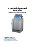
The sampler is housed in a resin transfer-molded fiberglass cabinet which is
designed for indoor or outdoor locations. No secondary enclosure is required.
The refrigeration compressor is located on top of the sampler to avoid
hydrogen sulfide and other corrosive, heavier than air gases. The
microprocessor in the sampler controller runs all refrigeration and heating
operations directly without relying on mechanical thermostats. No mechanical
thermostat adjustments are required. All temperature settings, setup, and
calibrations are performed via the front panel.
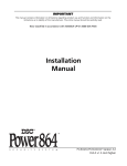
1.1 Controller Cover
The lockable top cover protects the controller compartment from extreme
weather as well as unauthorized use. When open, it is supported with a
simple rod and clip similar to a car hood support (see Figure 1). Padlocks are
available from the manufacturer (Cat. No. 954).
Figure 1
Controller Cover
1.2 Controller Compartment Heater
The optional 500 watt controller compartment heater provides several
benefits in colder climates:
•
Prevents residual liquid from freezing in the pump.
•
Pump tubing stays resilient, prolonging the life of the tubing, pump rollers,
motor, and gear box.
•
Prevents ice and snow from building up on the cover.
•
Keeps LCD functional and electronics from temperature extremes.
The compartment heater operation is microprocessor controlled and
automatic.
1.3 Refrigeration Compartment Door
The lockable front door opens by pressing the round button in the center of
the latch. When closing the door, flip the latch closed to pull the door tight.
Two keys are provided for the door lock.
Since the door gasket may compress slightly over time, an adjustment screw
is provided to allow the door to be tightened. Loosen the lock nut before
making adjustments and retighten the lock nut when done (Figure 2).
8854intro.fm
Page 13
Introduction
Section 1
Figure 2
Door Latch
Lock Nut
Door Tension
Adjustment
Screw
1.4 Interface Connectors
Interface connectors are located on the left side of the controller housing. An
optional weather tight terminal box located on the back of the sampler
provides conduit termination for all input/output lines.
The sampler comes standard with two interface receptacles.
•
12 V dc (Power Input)
•
Auxiliary (Multi-purpose input/output port)
•
RS232 (Serial communications port)
•
Thermal (Control port for heating and cooling system)
In addition, the sampler can be used with a wide variety of optional devices
including level and flow sensors, rain gauge, pH/ORP, D.O., temperature,
conductivity, Modem, 4–20 mA current loop, and three additional analog
inputs of 4–20 mA or -4.0 V dc to +4.0 V dc.
Figure 3
Controller Housing Connectors
1
12 V dc
2
RS232
4
3
Thermal
1.
12 V dc
Page 14
Interface Connectors
2.
RS232
AUX
3.
Thermal
4.
Auxiliary
8854intro.fm
Section 1
1.4.1 Receptacle Caps
Interface receptacles are covered with push-on receptacle caps. These caps
protect the connector pins from dirt and moisture and should be attached to
any receptacle not in use.
1.5 Front Panel
The front panel of the sampler consists of the keypad, liquid crystal display,
and the internal case humidity indicator.
Figure 4
Front Panel
8
1
7
2
3
6
5
4
1.
Soft Keys
5.
Power OFF Key
2.
Manual Mode Key
6.
Main Menu Key
3.
Run/Stop Key
7.
Status Bar
4.
Power ON Key
8.
Menu Bar
1.5.1 Keypad Description
The keypad includes the numeric keypad, soft keys, and function keys.
Numeric Keypad
The numeric keypad consists digits 0 through 9, a +/- key, and a decimal key.
“Soft” Keys
Soft keys are blank, white keys located to the left and right of the display.
The appearance of each function key depends on the display. The key is not
active when there is no function displayed. The soft keys appear on the
display and point to the proper soft key to push for that action.
8854intro.fm
Page 15
Front Panel
Section 1
In some cases during a programming step an item from a list needs to be
selected. The soft keys on the right side of the display will change to display
“up” and “down” arrows. Scroll up and down the list of choices.
Power ON/OFF Key
Press ON to turn the instrument on, a green light will flash to indicate power is
active. To turn the instrument off, press OFF.
Function Keys
There are three function keys that are used while operating the sampler (see
Table 1). These functions are dedicated keys to allow quick access. They are
the white keys located just above the numeric keypad.
Table 1 Function Key Descriptions
Main Menu
This is the starting point to get to any other point in the program. Press the Main Menu key at any time during
programming to return to the Main Menu Screen. The current action is cancelled if changes are not yet accepted.
Manual Mode
Manually controls the operation of the sample pump and the distributor arm.
ADVANCED DISTRIBUTOR soft key: Moves the distributor arm to the user selected bottle. Used to verify the operation of
the distributor or when repositioning the arm if it was moved by hand.
GRAB SAMPLE soft key: Takes a sample in the same manner as when a program is running. Includes all pre-rinses and
sample retries, if programmed.
PUMP OPERATION soft key: Allows manual control of the pump in both forward and reverse directions. Once started, the
pump is stopped by pressing any key.
Run/Stop
Runs (or resumes) a program and stops a currently running program.
1.5.2 Liquid Crystal Display
Table 2 LCD Displays
Menu Bar
The Menu Bar appears in a black band on the top edge of the display. The upper left corner of the menu bar
shows the time and date. The upper right corner shows the name of the current menu (Figure 4).
Status Bar
The Status Bar appears along the bottom edge of the display. The appearance of the status bar changes
depending upon the function performed (Figure 4). The lower left corner of the Status Bar indicates whether a
program is Complete, Running, Halted, or Ready To Start. If it is not needed during a programming step, it
disappears. The lower right corner displays system alarm conditions, such as low memory battery, jammed
distributor etc. For a list of possible alarms refer to section 6.4 on page 87. The status bar also lists the valid
choices when entering certain programming information.
1.5.3 Internal Humidity Indicator
The internal case humidity indicator (Cat. No. 2660) turns pink when the
internal case humidity exceeds 60 percent.
The sampler is equipped with an internal desiccant module (Cat. No. 8849) to
absorb any humidity trapped in the case during final assembly. Under normal
operating conditions, this desiccant provides long-term protection against
condensed moisture inside the case.
Replacement of the internal desiccant module is only necessary if the
indicator turns pink. See to section 7.10 on page 101 for details.
Page 16
Front Panel
8854intro.fm
INSTALLATION
DANGER
Some of the following manual sections contain information in the form of warnings, cautions and notes
that require special attention. Read and follow these instructions carefully to avoid personal injury and
damage to the instrument. Only personnel qualified to do so, should conduct the installation/maintenance
tasks described in this portion of the manual.
DANGER
Certains des chapitres suivants de ce mode d’emploi contiennent des informations sous la forme
d’avertissements, messages de prudence et notes qui demandent une attention particulière. Lire et suivre
ces instructions attentivement pour éviter les risques de blessures des personnes et de détérioration de
l’appareil. Les tâches d’installation et d’entretien décrites dans cette partie du mode d’emploi doivent être
seulement effectuées par le personnel qualifié pour le faire.
PELIGRO
Algunos de los capítulos del manual que presentamos contienen información muy importante en forma de
alertas, notas y precauciones a tomar. Lea y siga cuidadosamente estas instrucciones a fin de evitar
accidentes personales y daños al instrumento. Las tareas de instalación y mantenimiento descritas en la
presente sección deberán ser efectuadas únicamente por personas debidamente cualificadas.
GEFAHR
Einige der folgenden Abschnitte dieses Handbuchs enthalten Informationen in Form von Warnungen,
Vorsichtsmaßnahmen oder Anmerkungen, die besonders beachtet werden müssen. Lesen und befolgen
Sie diese Instruktionen aufmerksam, um Verletzungen von Personen oder Schäden am Gerät zu
vermeiden. In diesem Abschnitt beschriebene Installations- und Wartungsaufgaben dürfen nur von
qualifiziertem Personal durchgeführt werden.
PERICOLO
Alcune parti di questo manuale contengono informazioni sotto forma d’avvertimenti, di precauzioni e di
osservazioni le quali richiedono una particolare attenzione. La preghiamo di leggere attentivamente e di
rispettare quelle istruzioni per evitare ogni ferita corporale e danneggiamento della macchina. Solo gli
operatori qualificati per l’uso di questa macchina sono autorizzati ad effettuare le operazioni di
manutenzione descritte in questa parte del manuale.
8854i_stop.fm
Page 17
INSTALLATION
Visit http: //www.hach.com
Section 2
Installation
DANGER
This instrument should be installed by qualified technical personnel to ensure
adherence to all applicable electrical codes.
2.1 Unpacking the Instrument
Remove the sampler from the shipping carton and inspect it for any damage.
Contact Hach Customer Service at 1-800-227-4224 if any items are missing
or damaged.
2.2 Selecting the Installation Site
DANGER
This product is not designed for
hazardous locations where
combustible environments
may exist.
Follow the simple guidelines below to allow complete drainage of the intake
line and prevent cross-contamination between samples.
•
Install the sampler as close to the sample source as site conditions permit
to increase pump tube life and optimize sampler performance.
•
Install the sampler above the sample source, with the intake tubing
sloping downward to the sample.
•
Make sure that the intake tubing is free of kinks or loops.
2.3 Installing the Sampler
The sampler can be installed using the optional anchor bracket mounting kit
(Cat. No. 8935).
1. Determine the proper site location for individual permanent installation.
2. Level the sampler using four leveling feet. Raise the sampler by turning
the feet clockwise.
3. Locate the screws around the base of cabinet. The front and rear screws
are used to mount the anchor brackets to the sampler.
4. Remove one screw from the cabinet. Slide the screw through the slot in
the anchor bracket and tighten halfway.
Note: Install only one bracket at a time. The sampler may become unstable if multiple
screws are removed at once.
5. With screw still loose, allow the anchor to drop down firmly in contact with
mounting surface (floor, concrete, etc.)
6. Assemble the remaining three brackets.
Note: A customer-supplied 7/16 bolt
or stud is recommended to ensure
secure mounting.
8854int.fm
7. Complete installation by securing the anchor brackets to the mounting
surface as required for individual installation.
Page 19
Installation
Section 2
Figure 5
Anchor Bracket Mounting Kit
1.7 cm
(0.66 in)
76.2 cm (30.0 in.)
70.13 cm (27.61 in.)
8.64 cm
(3.40 in.)
48.26 cm
(19.00 in.)
3.05 cm
(1.20 in.)
1.9 cm
(0.75 in.)
72.92 cm
(28.71 in.)
A
73.41 cm
(28.90 in.)
76.76 cm
(30.22 in.)
B
86.4 cm
(34.0 in.)
Minimum Pad Size
2
1
Standard Mounting
A.
AWRS Footprint with Optional Anchor Frame
1.
Level Foot Mounting
2.
3
Standard Mounting w/
Optional Anchor Bracket
B.
AWRS Permanent Installation Mounting Pad
7/16 Bolt or Stud Recommended (not supplied)
3.
2 Places Each Side
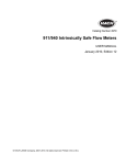
2.4 Installing the Pump Tube in the Sensor Body
Note: Do not stretch the tubing in
the sensor body, as this could affect
the ability of the sensor to detect
liquid through the pump tubing.
1. Remove the four screws on the pump cover.
2. Remove the front cover of the pump housing. Remove the tubing. Locate
the black dots on the tubing. The end of the tube that extends farthest
beyond the black dot attaches to the stainless steel tubing connector.
3. Install the pump tube in the pump housing so the black dots are visible
just outside the pump body.
Note: You must use the proper
length of silicone tubing in the pump
body. An improper length can
reduce the life of the tubing and
pump rollers. Refer to Figure 6 for
the correct length.
4. After inserting the new pump tube as shown, reinstall the front cover and
secure it with the four screws until finger tight.
5. Make sure that the tubing extends through the liquid sensor and out of the
controller as shown in Figure 7.
Page 20
Installing the Pump Tube in the Sensor Body
8854int.fm
Section 2
Figure 6
Pump Tube Loading
Figure 7
Installing Pump Tube Through the Sensor Body
2.4.1 Attaching the Intake Line
Attaching the Vinyl Tubing
The connection kit (Cat. No. 2248) contains two identical assemblies, one for
connecting vinyl tubing to the tubing attached to the sampler, and the other for
connecting the vinyl tubing to an intake strainer or remote pump. The kit
contains four hose clamps and two stainless steel tubing connectors.
1. Push one end of the tubing connector into the vinyl tubing attached to the
controller until the tubing abuts the shoulder of the tubing connector.
Secure with a tubing clamp (Figure 8).
2. Push the other end of the tubing connector into the vinyl tubing until the
tubing abuts the shoulder of the tubing connector and secure with a
tubing clamp (Figure 8).
3. Repeat Step 1 and Step 2 for the fitting that connects the vinyl tubing to
an intake strainer or a remote pump.
8854int.fm
Page 21
Installing the Pump Tube in the Sensor Body
Section 2
Figure 8
3/8” Vinyl Tubing Connector
1.
Vinyl tubing to controller
3.
Tubing clamp (2 required)
2.
Vinyl tubing to strainer or pump.
4.
Stainless steel tubing connector
Attaching the Teflon®-Lined Tubing
The Connection Kit for Teflon-lined Tubing (Cat. No. 2186) contains two
identical assemblies, one for connecting the Teflon-lined tubing to the
stainless steel tubing connector and the other for connecting the Teflon-lined
tubing to the intake strainer. The kit contains six clamps, two lengths of
silicone tubing, and two stainless steel barbed fittings.
To connect the Teflon-lined tubing follow the instructions and Figure 9 below:
1. Place the Teflon-lined tubing over the tubing connector nipple until it abuts
the shoulder of the tubing connector and secure with a tubing clamp.
2. Place one end of the silicone tubing over the wide end of the tubing
connector and secure with a tubing clamp.
3. Slide a second tubing clamp over the other end of the silicone tubing.
Push the silicone tubing over the stainless steel fitting on the intake
strainer and tighten the tubing clamp.
4. Repeat the procedure for the fitting that connects the Teflon-lined tubing
to the silicone pump tubing.
Page 22
Installing the Pump Tube in the Sensor Body
8854int.fm
Section 2
Figure 9
3/8″
ID Teflon-lined Tubing Attached to Intake Strainer and Tubing Connector
1.
Intake strainer
4.
Stainless steel tubing connector
2.
Tubing clamp (3 required)
5.
Teflon-lined intake tubing
3.
Two-inch piece of silicone tubing
6.
Wide end of stainless steel tubing connector
2.4.2 Setting Up the Intake Line and Strainer
Note: If site conditions do not permit
the intake to slope downward from
the sampler to the sample source,
disable the liquid sensors and
calibrate the sample volume using
the Timed Calibrate method when
programming the sampler.
For each sampling location, the intake line should be as short as practical,
and be free of any sharp bends, coils, or loops. Install the intake line with a
downward slope from the sampler to the sample source because:
•
This will ensure the complete drainage of the intake line when it is
air-purged before and after each sample, and will help to prevent
cross-contamination of the individual samples.
•
Complete drainage is important in freezing conditions, as any liquid slugs
that remain could freeze and plug the line.
Place the sample intake and strainer in the mainstream of the sampling
source, in an area of turbulent and well mixed flow.
Note: Vertical lift should not exceed
27 ft. If your site requires more lift,
you may purchase the Remote
Pump Option. See Parts and
Accessories on page 147.
Also, you must account for the vertical location of the intake. A position too
near the surface may yield excess lighter materials, while a position too near
the bottom may yield excess heavy materials. The constituents of interest
must be considered when positioning the intake strainer.
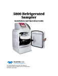
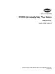
2.5 Choosing Bottle and Retainer Configurations
A broad range of bottle configurations is available for the Sigma 900 MAX All
Weather Refrigerated Sampler.
8854int.fm
Page 23
Choosing Bottle and Retainer Configurations
Page 24
Choosing Bottle and Retainer Configurations
(24) 350 mL Glass Bottles
(Cat. No. 732)
(24) 1 Liter Polyethylene Bottles
(Cat. No. 737)
(8) 1.9 Liter Glass Bottles
(Cat. No. 1118)
(8) 2.3 Liter Polyethylene Bottles
(Cat. No. 657)
(4) 2.5 Gal Glass Containers
(Cat. No. 2317)
(4) 3 Gal Polyethylene Containers
(Cat. No. 2315)
(2) 2.5 Gal Glass Containers
(Cat. No. 2318)
(2) 3 Gal Polyethylene Containers
(Cat. No. 2316)
Full
Container
Shut-Off
(8847)
Distributor
Assembly
(8843)
w/ Arm
(8846)
Bottle Tray
(1511)
Retainer
(1521)
Distributor
Assembly
(8842)
w/ Arm
(8845)
Retainer
(1322)
Distributor Retainer
Assembly (1056)
( 8841)
w/ Arm
(8844)
Figure 10
6 Gal Polythethylene Container
(Cat. No. 6494)
900 MAX
All Weather
Refrigerated
Sampler
(Cat. No. 3543)
Composite
Tube
Support
(8838)
Section 2
Bottle Configurations
8854int.fm
Section 2
2.6 Setting Up the Bottles
2.6.1 One-Bottle Sampling
For single bottle composite sampling, install the Full Bottle Shut-off (refer to
Section 2.8 on page 28) and place the bottle in the center of the bottle tray
(Figure 16 on page 28). The Full Bottle Shut-off positions the sample tubing
over the bottle mouth.
2.6.2 Two- and Four-bottle Sampling
For two-bottle sampling, install the distributor (refer to Section 2.7 on page 26)
and place the bottles in the Bottle #1 and Bottle #2 positions in the tray as
shown in Figure 11.
For four-bottle sampling, install the distributor and place all four bottles in the
tray as shown in Figure 12.
Figure 11
Two-bottle Locations
2
2
3
1
1
Front
1.
Single Bottle Location
Figure 12
2.
Two Bottle Location
3.
Slots for Wire From Bottle Tray (8 or 24
bottle)
Four-bottle Locations
1
2
3
1
4
2
Front
1.
1, 2, or 4 Bottle Locations
2.
Slot for Wire From Bottle Tray (8 or 24 bottles)
2.6.3 Eight-, 12-, or 24-bottle Sampling
For eight-, 12- or 24-bottle sets, install the distributor (refer to section 2.7 on
page 26). Place the bottles in the tray and install the proper bottle retainer
(Figure 13).
Bottle #1 is the first bottle clockwise (looking down on the tray) from the right
side of the tray. Bottle #1 is located on the inside of each bottle tray for all
multiple bottle sets (Figure 13).
8854int.fm
Page 25
Setting Up the Bottles
Section 2
Figure 13
Eight-, 12-, or 24-bottle Configuration
1
2
3
1.
Distributor
2.
Retainer
3.
Bottles and Bottle Tray
2.7 Installing the Distributor
Note: Make sure the sampler is
powered off before removing or
installing the distributor.
For multiple bottle sampling, a motorized arm (Distributor) is provided to
automatically position the sample tube over the proper bottle. The
microprocessor-controlled distributor arm can automatically locate two, four,
eight, 12, or 24 discrete bottles.
To install the distributor:
1. Locate the two slots along one edge of the distributor assembly base
plate (Figure 15). Slide the distributor assembly, slots first, under the
shoulder screws located on the top inside surface of the controller
section.
2. When fully seated, hand tighten the knurled thumbscrew to hold the
distributor in place.
3. To ensure the arm has sufficient freedom of movement, hand-rotate the
arm to the opposite end of the Arm Stop.
4. Install the silicone distributor tubing to the sample fitting on the top
underside surface of the controller housing.
Note: Do not force the arm past the Arm Stop clip. The Arm Stop keeps the arm from
being rotated more than 360 degrees. This keeps the distributor tubing from
kinking.
The distributor tubing should be installed so that the end of the tubing extends
out of the nozzle end of the distributor arm no more than 1/8 in. (Figure 14). Do
not let the tubing extend more than 1/8 in. past the nozzle end of the arm.
Page 26
Installing the Distributor
8854int.fm
Section 2
2.7.1 Distributor Arm Alignment
1. Program the sampler for 24-bottle operation.
2. Press START PROGRAM to set the distributor shaft to the
Bottle #1 position.
3. Place the arm on the distributor shaft and align the rib on the inside wall of
the control housing skirt.
4. Secure the arm to the shaft by tightening the 1/8 in. hex-head screw,
located on the distributor arm.
Figure 14
Distributor Tubing in Arm
1
2
1.
Distributor Shaft
Figure 15
2.
Nozzle End (1/8 in. max)
Distributor Installation
2
3
1
1.
Thumbscrew
8854int.fm
4
2.
Shoulder Screws
3.
Distributor Assembly
4.
Distributor Arm
Page 27
Installing the Distributor
Section 2
2.8 Installing the Full-Bottle Shut-Off Device
1. Install the rubber grommet into the hole provided in the cap of the
composite bottle.
2. Slide the Full Bottle Shut-Off, float first, into the bottle through the center
of the grommet.
3. Insert the Full Bottle Shut-Off connector into the receptacle (Figure 16).
Figure 16
Full Bottle Shut-off Installation
1
1.
Full Container Shut-off (Cat. No. 8847)
2.9 Power Connections
Note: Install the sampler on its own
circuit to ensure a continuous,
stable source of power.
The sampler refrigerator operates on 120 V ac (100 and 230 V ac optional),
and has an internal circuit breaker in the Power Junction Assembly Control
Box located in the upper rear compartment (see section 7.12 on page 102).
The controller requires 12 V dc which is supplied via an internal ac/dc power
converter. The unit may be ordered with a 3-prong ac power cord or a conduit
connection suitable for a junction box and hard-wire permanent installation.
Important: Whenever electricity is present, there is a possibility of electrical
shock. Before connecting the sampler to an ac power source, take the
following safety precautions:
1. Check the power source to make sure that it satisfies the ac power
requirements of the sampler.
2. Make sure that all electrical installations and connections are in
accordance with national and local electrical codes.
3. Disconnect the sampler from the power source.
4. Do not attempt to make any connection or otherwise handle the electrical
components of the sampler when connected to ac line power if the
immediate area is wet, or if hands or clothing are wet.
5. If the circuit breaker or fuse in the ac power source is tripped, determine
the cause before restoring power to the sampler.
Page 28
Installing the Full-Bottle Shut-Off Device
8854int.fm
Section 2
6. Make sure the power circuit is grounded and protected with a Ground
Fault Interrupter (GFI).
2.10 Auxiliary Receptacle Pin Identification
F
A
E
B
D
C
Pin A/White (12 V dc)
Powers an external device or flow meter. Must be used in conjunction with Pin B (ground).
Pin B/Blue (Ground)
Connected to dc ground and is isolated from the earth ground found in the ac power line.
Pin C/Yellow (Pulse Input)
With the sampler in Flow Proportional mode and connected to an external flow meter, a 5 to
12 V dc input pulse lasting at least 25 milliseconds will cause the sampler to decrement one
count. The 12 V dc line found on Pin A can be used directly with a simple contact closure to
Pin C or an external 5 to 12 V dc pulse may be applied providing the ground side of the
external signal is connected to the sampler ground at Pin B. This count is actuated at the
beginning of the input signal (the leading edge of the pulse).
Pin D/Black
(Liquid Level Actuator/
Auxiliary Control Input)
This line is held at 5 V dc inside the sampler. When shorted to ground (Pin B), a signal is sent
to the microprocessor inside the sampler causing it to “wake up” and begin or resume its
sampling program. It can be used in conjunction with a simple level float to actuate the
sampler when liquid is present or to take over after a second sampler has finished its
program. It may also be used with any device (such as a pH meter) that produces a dry
contact output to control the sampler in response to some user-defined condition (i.e. high or
low pH); must be used in conjunction with Pin B.
Pin E/Red (Special Output)
Normally at 0 V dc, this line goes to 12 V dc upon any of the selected events.
Normally an open circuit, this line switches to ground for 90 seconds at the conclusion of the
sampling program. Used to “wake up” another sampler to take over sampling or to signal an
Pin F/Green
operator or data logger upon the completion of the sampling program. This pin is also used to
(Program Complete Output)
signal the bottle full condition in a single bottle/continuous mode, and will transmit the bottle #
to a 950 Flow Meter if the program complete signal is disabled.
2.10.1 Splitter Interface
Use the Splitter Interface (Cat. No. 939) when more than one of the signals
listed above are needed simultaneously. Connecting the interface to the 6-pin
connector on the sampler provides three additional connectors. Two or more
interfaces may be connected in series to allow for additional connections.
Figure 17
8854int.fm
Splitter Interface
Page 29
Auxiliary Receptacle Pin Identification
Section 2
2.11 Thermal Control
The thermal control port is used to connect the sampler controller to the
Power Supply/Thermal Control Box located inside the sampler back cover of
the unit. This port carries all temperature measurement, refrigeration, and
heating control signals.
Table 3Thermal Control Pin Assignments
Pin
Signal Description
Wire Color
A
TS-1
Orange
B
TS-2
Brown
C
TS-3
Yellow
D
Heat
Black
E
V AD+
Red
F
AD Ref
Green
G
Evaporator Heater
Purple
H
Compressor Fan
Gray
J
A Ground
Blue
K
Ground
White
Page 30
Thermal Control
8854int.fm
OPERATION
DANGER
Handling chemical samples, standards, and reagents can be dangerous. Review the necessary Material
Safety Data Sheets and become familiar with all safety procedures before handling any chemicals.
DANGER
La manipulation des échantillons chimiques, étalons et réactifs peut être dangereuse. Lire les Fiches de
Données de Sécurité des Produits (FDSP) et se familiariser avec toutes les procédures de sécurité avant
de manipuler tous les produits chimiques.
PELIGRO
La manipulación de muestras químicas, estándares y reactivos puede ser peligrosa. Revise las fichas
de seguridad de materiales y familiarícese con los procedimientos de seguridad antes de manipular
productos químicos.
GEFAHR
Das Arbeiten mit chemischen Proben, Standards und Reagenzien ist mit Gefahren verbunden. Es wird dem
Benutzer dieser Produkte empfohlen, sich vor der Arbeit mit sicheren Verfahrensweisen und dem richtigen
Gebrauch der Chemikalien vertraut zu machen und alle entsprechenden Materialsicherheitsdatenblätter
aufmerksam zu lesen.
PERICOLO
La manipolazione di campioni, standard e reattivi chimici può essere pericolosa. La preghiamo di prendere
conoscenza delle Schede Techniche necessarie legate alla Sicurezza dei Materiali e di abituarsi con tutte
le procedure di sicurezza prima di manipolare ogni prodotto chimico.
8854o_stop.fm
Page 31
OPERATION
Visit http: //www.hach.com
Section 3
Basic Programming Setup
3.1 Initial Power-Up of Sampler
After pressing the ON key, the sampler performs a complete diagnostic test
and displays the menu shown when the unit was last turned off. Set the
instrument programming features when the Main Menu is displayed. The
Main Menu is the starting point for all programming operations. The Main
Menu offers four choices:
•
Setup—Basic and Advanced Sampling programming
•
Status—Lists all current sampling status, power supply voltage, and
values of any data channels that are enabled.
•
Display Data—Shows graphs and tables of logged data
(Displaying Data on page 112)
•
Options—Optional Device Programming
Setup and Option functions lead to sub-menus and will configure the basic
and advanced features of the sampler. Refer to the Quick Start Guides on
page 103. The Display Data and Status Menus lead to sub-menus and will
provide information only. Press STATUS to display any data channels that
have enabled logging (flow, pH, temp., etc.)
11:00 AM 21 - APR - 01
* MAIN MENU*
DISPLAY DATA
SETUP
OPTIONS
STATUS
READY TO START
3.2 Basic Programming Setup
Basic programming setup must be performed, step-by-step and in its entirety,
after the instrument is installed. Refer to the Quick Start Guides on page 103
for more information. The basic program setup will modify the following items:
•
Bottles
•
Intake Tubing
•
Program Lock
•
Program Delay
•
Sample Collection
•
Sample Distribution
•
Liquid Sensor
•
Sample Volume
•
Intake Rinses
•
Sample Retries
•
Site ID
In addition, several advanced sampling features are found on a sub-menu
called Advanced Sampling. Refer to section 3.3 on page 46 for Advanced
Sampling Basic Programming Setup.
8854pgm.fm
Page 33
Basic Programming Setup
Section 3
To make changes to the program entries after the basic programming setup,
press the MAIN MENU key and select SETUP>MODIFTY SELECTED ITEMS and
highlight the program entry using the UP and DOWN keys.
To review all information in the Setup and Option menus without worrying
about accidentally changing the information. Use the Review All Items
function to verify that the program is setup properly. For more information on
this function refer to Review All Items on page 111.
1. Press SETUP from the Main Menu to prepare the instrument for use.
11:00 AM 21 - APR - 01
* MAIN MENU*
DISPLAY DATA
SETUP
OPTIONS
STATUS
READY TO START
2. From the Main Menu select SETUP>MODIFY ALL ITEMS.
11:00 AM 21 - APR - 01
* MAIN MENU*
MODIFY
ALL ITEMS
REVIEW ALL
ITEMS
READY TO START
MODIFY
SELECTED ITEMS
3. Press ACCEPT to begin setting up the Bottles.
Step 1 - Bottles
1-A. Enter the total number of sample bottles in the refrigeration
compartment, using the numeric keypad.
11:00 AM 21 - APR - 01
ACCEPT
BOTTLES
NUMBER OF BOTTLES:
—
CLEAR
ENTRY
BACKUP
ENTER: 1, 2, 4, 8, 12, OR 24
Note: The bottles may be installed directly in the refrigeration compartment or in the
removable bottle tray when using sets greater than four bottles.
1-B. Press ACCEPT to continue and move to the Bottle Volume menu.
Page 34
Basic Programming Setup
8854pgm.fm
Section 3
1-C. Enter the bottle volume and select gallons or milliliters using the
CHANGE UNITS key.
11:00 AM 21 - APR - 01
ACCEPT
BOTTLES
BOTTLE VOLUME
——
CHANGE
UNITS
CLEAR
ENTRY
BACKUP
ENTER: 0.500—99.90
1-D. Press ACCEPT and continue to Intake Tubing.
Step 2 - Intake Tubing
11:00 AM 21 - APR - 01
ACCEPT
INTAKE TUBING
INTAKE TUBE LENGTH:
_____
CHANGE
UNITS
CLEAR
ENTRY
BACKUP
ENTER: 3—99
2-A. Enter the intake tube length of the intake tubing attached to the
sampler. Length values from 100 to 3000 cm (3 to 99 ft) are valid.
Change the measurement unit using the CHANGE UNITS key.
Note: Intake tube length affects sample volume accuracy, cut the tubing to the nearest
whole foot. Avoid excessively long tubing runs. Doubling the intake tubing length
can quadruple the pump tubing wear if intake rinses or sample retries are
enabled. Always locate the sampler close to the sample liquid source to minimize
tubing, pump, motor, and gearbox maintenance.
2-B. Press ACCEPT to move to the Intake Tube Type menu.
2-C. Select the type of intake tube (3/8 in. Vinyl, ¼ in. Vinyl, 3/8 in. Teflon®)
using CHANGE UNITS key.
2-D. Press ACCEPT to select the intake tube type and continue with Program
Lock.
Step 3 - Program Lock
Note: The program lock password is
configured at the factory as “9000”
and cannot be changed.
Enabling the Program Lock will provide a protective “password” which will
keep unauthorized personnel from tampering with the instrument keypad.
3-A. Enable or Disable Program Lock using the CHANGE CHOICE key.
Note: When program lock is enabled and a user attempts to make a change in the
program, a screen will ask the operator to enter the password. The operator must
enter 9000 and press ACCEPT.
3-B. Press ACCEPT to continue the basic program setup and continue with
Program Delay.
8854pgm.fm
Page 35
Basic Programming Setup
Section 3
Step 4 - Program Delay
Note: If both Setpoint Sampling and
Program Delay are enabled, the
program delay is evaluated first,
prior to any checking for
setpoint conditions.
4-A. Enable or Disable Program Delay using the CHANGE CHOICE key.
Enabling the Program Delay will cause the sampling program to delay
starting until a user specified time and day of week are programmed.
4-B. After enabling the program delay, enter the time and day of week that
the program will begin. Use the soft keys to change the day of week as
well as the AM/PM indicator.
11:00 AM 21 - APR - 01
ACCEPT
PROGRAM DELAY
CHANGE
AM/PM
START PROGRAM:
00:00 AM MON
CLEAR
ENTRY
CLEAR
DAY
(USE THE NUMERIC KEYPAD)
4-C. Press ACCEPT to continue with Sample Collection.
Step 5 - Sample Collection
5-A. Select the type of sample collection; Time Proportional,
Flow- Proportional Constant Volume, Variable Time (CVVT), or
Flow-Proportional Constant Time, Variable Volume (CTVV).
11:00 AM 21 - APR - 01
ACCEPT
SAMPLE COLLECTION
SAMPLE COLLECTION
_______________
CHANGE
CHOICE
BACKUP
CHOICES: TIMED, FLOW PROPORTIONAL
Timed-Proportional Sampling Intervals
When the program starts, a sample is taken immediately or delayed until after
the first interval has elapsed. Select either, Take First Sample Immediately or
After the First Interval.
Timed-Proportional samples are taken each time a user defined time interval
has elapsed. Samples can be continually taken at that interval until the
completion of the program.
a. From the Sample Collection menu, press CHANGE CHOICE until
Timed Proportional is displayed. Press ACCEPT to continue.
11:00 AM 21 - APR - 01
ACCEPT
SAMPLE COLLECTION
SAMPLE COLLECTION
TIMED PROPORTIONAL
CHANGE
CHOICE
BACKUP
CHOICES: TIMED, FLOW PROPORTIONAL
Page 36
Basic Programming Setup
8854pgm.fm
Section 3
b. Enter the Interval Between Samples. Press ACCEPT to continue.
11:00 AM 21 - APR - 01
SAMPLE COLLECTION
ACCEPT
INTERVAL:
00:00 (hrs:min)
CANCEL
CLEAR
ENTRY
ENTER: 000:01—999.00 (hrs:min)
c. Select Take First Sample Immediately or After The First Interval?
Note: When the program is started, the first sample is taken immediately upon
pressing the start button or after the first interval has elapsed.
11:00 AM 21 - APR - 01
ACCEPT
SAMPLE COLLECTION
CHANGE
CHOICE
TAKE FIRST SAMPLE:
_______________
CANCEL
CHOICES: IMMEDIATE, AFTER 1st SAMPLE
d. Press ACCEPT to continue to Sample Distribution.
Flow Proportional Constant Volume, Variable Time (CVVT)
CVVT sampling is a flow-proportional method of sampling. CVVT samples are
taken when a user-defined flow volume occurs in the flow stream. This occurs
when the sampler is programmed to take a sample every time a specified
volume of flow occurs in the flow stream. Specified flow volume intervals can
vary with the flow rate of the stream, therefore varied time intervals can occur
when constant (fixed) volume occurs.
Flow volume is determined internally, by the optional integral flow meter or by
an external flow meter.
a. In the Sample Collection, press CHANGE CHOICE until Flow
Proportional is displayed. Press ACCEPT.
11:00 AM 21 - APR - 01
ACCEPT
SAMPLE COLLECTION
CHANGE
UNITS
SAMPLE COLLECTION:
FLOW-PROPORTIONAL
CANCEL
ENTER: 1.00 - 99999999
b. In the Flow Proportional menu, press CHANGE CHOICE until Constant
Volume, Variable Time is displayed. Press ACCEPT.
11:00 AM 21 - APR - 01
ACCEPT
FLOW PACING
CHANGE
CHOICE
FLOW PACING MODE:
CONST VOL / VAR TIME
CANCEL
CHOICES: VAR T / CST VOL, CST T / VAR VOL
8854pgm.fm
Page 37
Basic Programming Setup
Section 3
c. Select either Integral or External flow meter and press ACCEPT.
d. Enter the flow volume between samples and select a unit of measure
using the CHANGE UNITS key, then press ACCEPT. Refer to Table 4
for flow unit choices.
11:00 AM 21 - APR - 01
ACCEPT
SAMPLE COLLECTION
CHANGE
UNITS
TAKE SAMPLE EVERY:
1500 gal
CLEAR
ENTRY
CANCEL
ENTER: 1.00—99999999
Table 4 Sampler Pacing Flow Units
Abbreviation
Volume
gal
gallons
ltr
liters
m3
cubic meters
af
acre-feet
cf
cubic feet
e. Enable or Disable Timed Over-Ride using the CHANGE CHOICE key.
Press ACCEPT, then enter a time period using the numeric keypad.
Note: Select Timed Over-Ride if the flow rate drops to an unusually low value
during flow-proportional sampling and if the sample is collected once an hour
for example, even if the flow interval has not elapsed.
11:00 AM 21 - APR - 01
ACCEPT
SAMPLE COLLECTION
TIMED OVER-RIDE:
00:00 (hrs:min)
CLEAR
ENTRY
CANCEL
ENTER: 000:01 — 999:00 (hrs:min)
f.
Select Take First Sample Immediately or After First Interval?
Note: When the program is started, the first sample is taken immediately upon
pressing the start button or after the first interval has elapsed.
11:00 AM 21 - APR - 01
SAMPLE COLLECTION
CHANGE
CHOICE
ACCEPT
TAKE FIRST SAMPLE:
_______________
CANCEL
CHOICES: IMMEDIATE, AFTER 1st SAMPLE
g. Press ACCEPT to continue to Sample Distribution.
Page 38
Basic Programming Setup
8854pgm.fm
Section 3
Flow Proportional Constant Time, Variable Volume Sampling (CTVV)
A Level-Velocity Sensor Input must be logged and electrically connected for
the CTVV feature to work correctly.
CTVV samples are taken at user-specified constant (fixed) intervals. However
the actual volume of each sampling is based on the known average flow rate
of the site, the actual metered flow rate for each specific interval, the total
sample volume desired, the user-specified collection period, and the specified
Sampling Interval. Depending on the flow volumes of a stream and various
intervals within the Collection Period, the volume of individual sampling can
vary. Also, the total sample collected during the entire period can carry slightly
above or below the Total Volume Desired. For these reasons, the
manufacturer advises using a sampling container that has a larger volume
than the Total Volume Desired value.
•
Sample Distribution menus are not available when CTVV is selected.
•
A level-velocity sensor input must be logged and electrically connected
for the CTVV feature to correctly work.
•
The Flow Pacing Mode menu within the Flow Proportional menus
sequence will not remember the previous setting whenever you re-enter
this menu, it will revert to the CVVT default. When re-entering this menu,
press CHANGE CHOICE to select the sampling method, CVVT or CTVV.
Example:
This is an example of how the instrument determines sample volume, based
on user inputs and actual metered flow volume.
The user entered values are the following:
•
Average Flow Rate (historical, site specific): 150 gph
•
Sampling Interval: 2 minutes
•
Total Sample Volume Desired: 1500 mL
•
Collection Sampling Period: 30 minutes
Calculation 1: Total Number of Samples
Sample Period - = 30
min.- = 15 samples total within specified period
-------------------------------------------------------------Sampling Interval
2 min.
Calculation 2: Average Sample Volume
Total
Sample Volume Desired- = -------------------------------------------1500 mL
------------------------------------------------------------------------------- = 100 mL/sample
Total Number of Samples
15 samples Total
Calculation 3: Sample’s Volume per unit of Flow Rate
Avg.
Sample Volume- = 100
mL/Sample- = 0.7mL/gph
----------------------------------------------------------------------------------------------Avg. Flow Rate
150 gph
Calculation 4: Actual Sample Volume to be Collected
Sample Volumes per unit of Flow Rate × Actual metered Flow Rate
0.7 mL/gph × 150 gph = 105 mL for this sample interval
8854pgm.fm
Page 39
Basic Programming Setup
Section 3
a. In the Sample Collection menu, press CHANGE CHOICE until Flow
Proportional is displayed. Press ACCEPT.
11:00 AM 21 - APR - 01
SAMPLE COLLECTION
CHANGE
UNITS
ACCEPT
SAMPLE COLLECTION:
FLOW-PROPORTIONAL
CANCEL
ENTER: 1.00 - 99999999
b. In the Flow Pacing menu, press CHANGE CHOICE Const Time/Var Vol
appears. Press ACCEPT.
11:00 AM 21 - APR - 01
FLOW PACING
CHANGE
CHOICE
ACCEPT
FLOW PACING MODE:
CONST TIME/ VAR VOL
CANCEL
CHOICES: VAR T / CST VOL, CST T / VAR VOL
c. In the Average Flow Rate menu use the numeric keypad to enter the
known historical Average Flow Rate for a particular site.
11:00 AM 21 - APR - 01
ACCEPT
CONST TIME/ VAR VOL
AVERAGE FLOW RATE:
150.00 gph
CLEAR
ENTRY
CANCEL
ENTER: 1.00—99999999
d. In the Interval menu use the numeric keypad to enter the time interval
between sample collections. Press ACCEPT.
11:00 AM 21 - APR - 01
ACCEPT
CONST TIME/ VAR VOL
INTERVAL:
0:02 (hrs:min)
CLEAR
ENTRY
CANCEL
ENTER: 1.00—999:00 (hrs:min)
e. In the Total Volume Desired menu use the numeric keypad to enter
the total volume of the sample. Press ACCEPT.
11:00 AM 21 - APR - 01
ACCEPT
CONST TIME/ VAR VOL
TOTAL VOLUME DESIRED:
1500 Ml
CLEAR
ENTRY
CANCEL
ENTER: 10—9999
Page 40
Basic Programming Setup
8854pgm.fm
Section 3
f.
In the Collection Period menu use the numeric keypad to enter the
time period for collecting samples.
11:00 AM 21 - APR - 01
ACCEPT
CONST TIME/ VAR VOL
COLLECTION PERIOD
0:30 (hrs:min)
CLEAR
ENTRY
CANCEL
ENTER: 000:01—999:00 (hrs: min)
g. Press ACCEPT to continue to Sample Distribution.
Step 6 - Sample Distribution
Sample distribution describes the way samples are deposited in a bottle(s).
Several bottle combinations are available with the sampler (Figure 10 on
page 24). Sample distribution is deposited into a single bottle or multiple
bottles. Multiple bottle applications use a distributor arm to automatically aim
the sample intake tubing into the proper bottle. Multiple bottle sets deliver
each sample to all bottles or deliver each sample into individual bottles or a
subset of bottles.
Single Bottle
6-A. Select either Stop After Last Bottle or Run Continuously? Stop After
Last Bottle mode stops the program when the sample is deposited into
the last bottle. Run Continuously mode continues running until it is
manually stopped.
11:00 AM 21 - APR - 01
ACCEPT
SAMPLE DISTRIBUTION
CHANGE
CHOICE
RUN MODE:
RUN CONTINUOUSLY
CANCEL
CHOICES: CONTINUOUS, STOP AFTER LAST
6-B. Press ACCEPT to continue to Liquid Sensor setup.
Multiple Bottle Sets
Multiple bottle applications use a distributor arm to automatically aim the
sample intake tubing into the proper bottle. Multiple bottle sets deliver each
sample to all bottles or deliver each sample into individual bottles or a subset
of bottles.
6-A. Select YES or NO for Deliver Each Sample to All Bottles.
11:00 AM 21 - APR - 01
ACCEPT
CANCEL
SAMPLE DISTRIBUTION
DELIVER EACH SAMPLE TO
ALL BOTTLES?
NO
CHANGE
CHOICE
CHOICES: YES, NO
8854pgm.fm
Page 41
Basic Programming Setup
Section 3
If NO is selected:
a. Select Samples per Bottle or Bottles per Sample.
Example 1: Samples Per Bottle
•
Bottles—8
•
Sample Collection; Time-Proportional; Sampling Interval—30 min.
•
Sample Distribution; Deliver Each Sample to All Bottles?— No
Samples Per Bottle— Yes
Number of Samples Per Bottle— 3
•
Sample Volume—100 mL
Every 30 minutes a sample is initiated. A 100 mL sample is drawn into
bottle #1, 30 minutes later a second sample is drawn into bottle #1,
30 minutes later a third sample is drawn into bottles #1. Thirty minutes
later the distributor arm advances to bottle #2 and a 100 mL sample is
drawn into bottle #2. The sequence continues until all bottles are filled.
Each bottle receives three samples before the distributor moves to the
next bottle.
Example 2: Bottles Per Sample
Note: A high pressure air purge is
automatically applied to the intake
tube between each sample
intake cycle.
•
Bottles—4
•
Sample Collection; Timed Proportional; Sampling Interval—30 min.
•
Sample Distribution; Deliver Each Sample to All Bottles?—No
Bottles Per Sample—Yes
Number of Bottles Per Sample—2
•
Sample Volume—1000 mL
Every 30 minutes a sample cycle is initiated. A 1000 mL sample is drawn
into the first bottle. the distributor arm immediately advances to bottle #2
and a 1000 mL sample is drawn into the second bottle. Thirty minutes
later, the distributor arm advances to bottle #3, and a 1000 mL sample is
taken. The distributor arm immediately advances to bottle #4 and a 1000
mL sample is drawn into the fourth bottle. The pattern continues each
sample cycle with each set of two bottles receiving a sample each time.
b. Press ACCEPT to continue with Liquid Sensor setup.
If YES is selected:
Each time a sample is taken it is consecutively placed in all bottles. This
allows for split samples.
a. Select Stop After Last Sample or Run Continuously.
11:00 AM 21 - APR - 01
ACCEPT
SAMPLE DISTRIBUTION
RUN MODE:
RUN CONTINUOUSLY
CHANGE
CHOICE
BACKUP
CHOICES: CONTINUOUS, STOP AFTER LAST
Page 42
Basic Programming Setup
8854pgm.fm
Section 3
b. If Stop After Last Sample is chosen, enter the samples to collect
using the numeric keypad.
11:00 AM 21 - APR - 01
SAMPLE DISTRIBUTION
ACCEPT
BACKUP
SAMPLES TO COLLECT:
2
CLEAR
ENTRY
ENTER: 1 — 999
Example 1: The following example creates four identical composite
samples automatically if the sampler is programmed as follows:
•
Bottles—4
•
Sample Collection; Sampling Interval—30 minutes
•
Sample Collection; Samples to Collect—25
•
Sample Volume—100 mL
Every 30 minutes a sample is initiated and a 100 mL sample is drawn into
the first bottle. The distributor arm advances to bottle #2 and 100 mL.
sample is drawn into the second. This also occurs in bottles #3 and #4.
Sampling will continue every 30 minutes until 25 samples are deposited.
Once all samples are deposited the program will terminate. If Run
Continuously is selected the sampling will restart automatically.
c. Press ACCEPT to continue to Liquid Sensor.
Step 7 - Liquid Sensor
The liquid sensor contains a pair of ultrasonic transducers which sense the
presence of liquid inside silicone tubing.
7-A. Enable or Disable Liquid Sensor using the CHANGE CHOICE key.
Note: Sample retries cannot be
enabled when the liquid sensor
is disabled.
Enabling the Liquid Sensor
When the liquid sensor is enabled, the sampler will perform two duties:
•
It senses when liquid reaches the pump during an intake cycle. The pump
then reverses to rinse the line, up to 3 times.
•
It senses the absence of liquid during a sample intake cycle if the intake
tubing is plugged or if the water level has dropped below the level of the
intake tube strainer. This initiates a Sample Retry if programmed
Disabling the Liquid Sensor/Timed Calibration
Disabling the liquid sensor turns the liquid sensor off. The sample volume is
then metered using a timed method (Timed Calibration), instead of a
sensed method.
7-B. Press ACCEPT to continue to Sample Volume.
8854pgm.fm
Page 43
Basic Programming Setup
Section 3
Step 8 - Sample Volume
Note: The minimum sample volume
is ten milliliters.
When multiple bottles are selected in Bottle Per Sample mode all bottles in a
subset receive a full sample volume. The volume is not divided among
the bottles.
8-A. Enter the desired volume of each sample using the numeric keypad.
Press ACCEPT to continue to Intake Rinses.
11:00 AM 21 - APR - 01
SAMPLE VOLUME
ACCEPT
BACKUP
SAMPLES VOLUME:
______
CLEAR
ENTRY
ENTER: 10 — 9999
Step 9 - Intake Rinses
9-A. Enter number of rinses using the numeric keypad.
11:00 AM 21 - APR - 01
INTAKE RINSES
ACCEPT
BACKUP
INTAKE RINSES:
0
CLEAR
ENTRY
ENTER: 0 — 3
Up to three intake rinses are enabled per sample cycle. After the sample
cycle’s initial purge has been completed, the sample liquid is drawn in until it
reaches the liquid sensor. The pump stops and purges the line before any
liquid enters the bottle. This is repeated up to three times before the actual
sample is taken and the line purged for the final time during that cycle.
Intake rinse can prevent cross contamination of samples. When the line is
purged at the end of each sample cycle, a few droplets of sample liquid may
cling to the inside walls of the tubing and the droplets are drawn in with the
following sample. Intake rinses will condition the intake line with a source
liquid that minimizes contamination from the previous sample.
9-B. Press ACCEPT to continue to Sample Retries.
Step 10 - Sample Retries
Note: Excessive intake tube line
lengths combined with multiple
Intake Rinses and Sample Retries
can increase the pump tube and
drive train wear. Locate the sampler
as close to the sample liquid source
as possible to minimize wear and
maintenance requirements.
Page 44
Basic Programming Setup
10-A. Enter the number of Sample Retries using the numeric keypad.
Up to three sample retries are enabled per sample cycle. After the initial purge
is completed, the sample liquid is drawn until it reaches the liquid sensor.
If the sample liquid does not reach the sensor within a reasonable time
(determined using the tubing length), the sample attempt is aborted, a purge
is initiated and the first of up to three sample retries is attempted.
8854pgm.fm
Section 3
After three attempts and no sample liquid has been collected, the cycle is
aborted, a Missed Sample is reported to the Sample History Log, and the
sampler begins a new sample interval.
10-B. Press ACCEPT to continue to Site ID.
Step 11 - Site ID
11-A. Enter a site identification number of up to 8 digits. This Site ID will
appear on all data printouts. This feature is useful when multiple sites
are monitored using a single flow meter or if data readings from multiple
flow meters are collected. Press ACCEPT.
11:00 AM 21 - APR - 01
SITE ID
ACCEPT
BACKUP
SITE ID:
00000000
CLEAR
ENTRY
(USE NUMERIC KEYPAD)
11-B. After Site ID is accepted the following menu will appear:
11:00 AM 21 - APR - 01
ADVANCED SAMPLING
DO YOU WISH TO
ACCESS THE ADVANCED
SAMPLING FEATURES?
YES
NO
ENTER: 1 — 999
11-C. If NO, the basic setup program is complete.
Note: To return to the Advanced Sampling options at a later time, from the Main Menu
select, SETUP>MODIFY SELECTED ITEMS>PROGRAM ENTRIES.
4. Highlight Advanced Sampling and press SELECT. In the Advanced
Sampling menu highlight the an item using the UP and DOWN keys and
press SELECT.
11:00 AM 21 - APR - 01
SELECT
PROGRAM ENTRIES
INTAKE RINSES
SAMPLE RETRIES
SITE ID
ADVANCED SAMPLING
RETURN
11-D. If YES, continue to Advanced Sampling, section 3.3.
8854pgm.fm
Page 45
Basic Programming Setup
Section 3
3.3 Advanced Sampling
Advanced sampling choices:
•
Program Complete Output
•
Timed Bottle Sets
•
Setpoint Sampling
•
Upset Sample
•
Special Output
•
Variable Intervals
•
Start/Stop Times
•
Variable Volumes
•
Storm Water
Step 12 - Program Complete Output
Program Complete Output sends a +12 V dc signal out Pin F of the Auxiliary
Receptacle at the completion of the sampling program. This signal is also
sent when a Full Bottle condition causes the program to complete. The
Program Complete signal remains on (+12 V dc) for 61 seconds and then
turns
back off (0 V dc).
Program Complete Output is used for the following purposes:
•
Multiple Sampler Operation. Samplers are arranged in a “Cascade”
control where the first sampler signals a second sampler to start its
program when the first sampler’s program is complete. This feature
requires the second sampler to be programmed for external
start operation.
•
To interface to a PC to signal the end of the sampling program.
•
To interface to a relay that trips a signal light in a control room to indicate
that sampling is finished and samples are ready to be picked up.
12-A. From the Advanced Sampling menu highlight Program Complete using
the UP and DOWN keys. Press SELECT to continue.
11:00 AM 21 - APR - 01
ADVANCED SAMPLING
SELECT
RETURN
PGM CMPLT OUTPUT
SETPOINT SAMPLING
SPECIAL OUTPUTS
12-B. Enable or Disable Program Complete using the CHANGE CHOICE key.
12-C. Press ACCEPT to continue to Setpoint Sampling.
Step 13 - Setpoint Sampling
Setpoint sampling allows the control of an automatic liquid sampler from one
of up to 14 sources. Setpoint sampling defines a set of limits that inhibit
sampling until an upset condition occurs, causing the limits to exceed.
Sampling is enabled only when the waste stream falls outside the setpoints.
Page 46
Advanced Sampling
8854pgm.fm
Section 3
13-A. Highlight Setpoint Sampling using the UP and DOWN keys on the
Advanced Sampling Menu. Press SELECT.
11:00 AM 21 - APR - 01
SELECT
RETURN
ADVANCED SAMPLING
PGM CMPLT OUTPUT
SETPOINT SAMPLING
SPECIAL OUTPUTS
START/STOP TIMES
13-B. Enable or Disable Setpoint Sampling using the CHANGE CHOICE key.
Press ACCEPT to continue.
13-C. Select either Start on Setpoint or Stop on Setpoint by pressing
CHANGE CHOICE. Press ACCEPT to continue.
•
Start on Setpoint will start a program when the setpoint condition is
met. The program continues to run even if the condition falls back
within the setpoint limits.
•
Stop On Setpoint halts the program if the setpoint condition falls back
within the setpoint limits and starts again if the limits are exceeded.
13-D. Highlight the desired channel to trigger from, then press SELECT.
13-E. Press either HIGH CONDITION or the LOW CONDITION.
11:00 AM 21 - APR - 01
SETPOINT CONDITION:
SETPOINT SAMPLING
HIGH
CONDITION
LOW
CONDITION
Note: Flow Rate of Change and Rainfall are signals that only increase and never
decrease in value, therefore these signals do not require Low Condition.
The external control signal must be configured on the external equipment for
the desired setpoint. An external control device must provide a dry contact
and can include a float switch, push-button, external flow meter, etc. For
interface connections refer to section 2.10 on page 29.
13-F. Enable or Disable the trigger point using the CHANGE CHOICE key.
13-G. Select the desired high or low trigger point using the numeric keypad.
Press ACCEPT to continue. Refer to Table 5.
11:00 AM 21 - APR - 01
ACCEPT
CANCEL
SETPOINT SAMPLING
SETPOINT SAMPLING:
HIGH TRIGGER POINT:
00000 in.
CLEAR
ENTRY
(USE NUMERIC KEYPAD)
8854pgm.fm
Page 47
Advanced Sampling
Section 3
13-H. Enter the Deadband value if required or, if programming Flow Rate Of
Change or Rainfall, enter a time interval that the flow or rainfall change
must take place (refer to section 6.4 on page 87).
11:00 AM 21 - APR - 01
ACCEPT
CANCEL
SETPOINT SAMPLING
SETPOINT SAMPLING
DEADBAND:
0.000
CLEAR
ENTRY
(USE NUMERIC KEYPAD)
13-I. Enter a delay when input is active. This delay will keep the program
from starting until the end of the delay period. Using the numeric
keypad, enter the delay in minutes and/or hours. Press ACCEPT.
11:00 AM 21 - APR - 01
ACCEPT
CANCEL
SETPOINT SAMPLING
DELAY WHEN INPUT
BECOMES ACTIVE:
(hrs:min)
CLEAR
ENTRY
(USE NUMERIC KEYPAD)
Table 5 Sampling Triggers and Settings
Channel
Sampling Trigger
Settings
1
Level
High and/or Low Condition, Deadband
2
Flow
High and/or Low Condition, Deadband
3
Flow Rate of Change
High Condition within Time Interval
4
pH or ORP
High and/or Low Condition, Deadband
5
Process Temperature
High and/or Low Condition, Deadband
6
Rainfall
High Condition within Timed Interval
7
Analog Input Channel 1
High and/or Low Condition, Deadband
8
Analog Input Channel 2
High and/or Low Condition, Deadband
9
Analog Input Channel 3
High and/or Low Condition, Deadband
10
Analog Input Channel 4 or DO
High and/or Low Condition, Deadband
11
Analog Input Channel 5 or DO Temperature
High and/or Low Condition, Deadband
12
Analog Input Channel 6 or Conductivity
High and/or Low Condition, Deadband
13
Analog Input Channel 7 or Conductivity
Temperature
High and/or Low Condition, Deadband
14
External Control
Configured in External Equipment
Page 48
Advanced Sampling
8854pgm.fm
Section 3
Step 14 - Special Output
The Special Output is a +12 V dc signal that appears on Pin E of the Auxiliary
Receptacle (refer to section 2.10 on page 29).
14-A. Highlight Special Output using the UP and DOWN keys on the Advanced
Sampling Menu. Press SELECT to continue.
11:00 AM 21 - APR - 01
SELECT
RETURN
ADVANCED SAMPLING
PGM CMPLT OUTPUT
SETPOINT SAMPLING
SPECIAL OUTPUTS
START/STOP TIMES
STORM WATER
14-B. Enable or Disable Special Outputs using the CHANGE CHOICE key.
Press SELECT to continue.
14-C. If enabled, select After Each Sample, Only When Pumping, or From
Rinse to Purge.
Bottle Number
If the Program Complete Output is disabled, then it is used in conjunction with
this special Output to transmit the bottle number to the connected device.
The Special Output signal can be configured to activate during one of the
following conditions:
•
After Each Sample– One second pulse at the completion of each sample
cycle. It signals an external datalogger or PC that a sample cycle was
initiated. When this choice is enabled, the sample success/failure is also
transmitted to the external datalogger by means of Pin F on the
Auxiliary connector.
•
Only When Pumping– During sample intake portion of cycle only, ignoring
all purges and rinse cycles. Used for tipping solenoid or ball valves when
sampling from a pressurized line.
•
From Rinse To Purge– During entire sample cycle, including all purge and
rinse cycles. Used for tripping solenoid or ball valves when sampling from
a pressurized line.
Step 15 - Start/Stop Times
Start/Stop Times start and stop a program at pre-arranged times. For
example, this feature can be used to run a program during weekdays and stop
the program during weekends, restarting on the following Monday. It can also
halt sampling for nighttime shutdowns.
Up to 12 Start and 12 Stop time entries can be set in any one program. Either
a Start Time and Date or a Start Time and Day of the Week may be selected.
8854pgm.fm
Page 49
Advanced Sampling
Section 3
15-A. Highlight the Start/Stop Time choices on the Advanced Sampling menu.
Press SELECT to continue.
11:00 AM 21 - APR - 01
PGM CMPLT OUTPUT
SETPOINT SAMPLING
SELECT
SPECIAL OUTPUT
START/STOP TIMES
STORM WATER
RETURN TIMED BOTTLE SETS
ADVANCED SAMPLING
15-B. Enable or Disable Start/Stop Times using the CHANGE CHOICE key.
Press ACCEPT to continue.
15-C. Press CHANGE CHOICE to select either Time/Date or Time/Weekday.
Select Time/Date if the start and stop times cover longer than a week.
Select Time/Weekday if the program repeats on a daily or weekly basis.
15-D. Press ACCEPT to continue.
15-E. Enter the Start Time #1, press ACCEPT to continue. Enter Stop Time #
and press ACCEPT to continue.
11:00 AM 21 - APR - 01
ACCEPT
START/STOP TIMES
PROGRAM START #
(TIME:DAY)
1
CLEAR
ENTRY
HIT CLEAR, THEN ACCEPT, AFTER LAST ENTRY
CHANGE
DAY
11:00 AM 21 - APR - 01
ACCEPT
CHANGE
AM/PM
START/STOP TIMES
PROGRAM STOP #
(TIME:DATE)
CLEAR
ENTRY
1
CHANGE
AM/PM
CHANGE
DAY
HIT CLEAR, THEN ACCEPT, AFTER LAST ENTRY
15-F. Continue entering Start and Stop times until finished. To exit and save
entries, enter a blank time and date. Press CLEAR ENTRY and then
press ACCEPT to continue to Storm Water.
Step 16 - Storm Water
EPA regulations for storm water discharges require monitoring of
precipitation, flow, and water samples in order to assess the impact of storm
or snow melt runoff on receiving waters. The manufacturer can help you
create a storm water monitoring system that consists of a multiple bottle
sampler, an external flow meter, and a tipping bucket rain gauge.
In addition to performing basic sampling routines, samplers that are equipped
with the storm water monitoring program have the following additional
capabilities:
Page 50
Advanced Sampling
8854pgm.fm
Section 3
•
The storm water sampling routine allows collection of automatic grab
sample(s) at user-selectable timed intervals (up to 24 different intervals
may be selected) during the storm's early stage or “first flush.” First flush
grab and main program flow-weighted composite samples are
automatically segregated. The first flush sample volume may be set
independently of the sample volume for the flow-weighted composite.
•
The special storm water program allows an external device to initiate the
start of the sampling program. A dry contact closure across Pins B and D
on the Auxiliary receptacle, held closed for at least 61 seconds, is
required.
•
When sampling with multiple bottles, the sampler can be programmed to
collect one large “first flush” sample (or small multiple samples) at timed
interval(s). The number of bottles segregated for the first flush sample is
selectable. Concurrently, flow-weighted samples are collected from the
beginning of the storm until all remaining bottle(s) are filled, or after a user
selected time has elapsed.
•
Storm water samplers are equipped with a special prerinse that occurs
only with the first sample collection. This “one time only” rinse ensures a
clean intake for installations that may remain dormant for extended
periods, and extends battery life by eliminating the prerinse for
subsequent samples.
16-A. Highlight Storm Water using the UP and DOWN keys on the Advanced
Sampling Menu. Press SELECT to continue.
11:00 AM 21 - APR - 01
SETPOINT SAMPLING
SPECIAL PUTPUT
SELECT
START/STOP TIMES
STORM WATER
TIMED BOTTLE SETS
RETURN UPSET SAMPLE
ADVANCED SAMPLING
16-B. Enable or Disable Storm Water using the CHANGE CHOICE key. Press
ACCEPT to continue.
16-C. Select a Start Condition using the CHANGE CHOICE key.
•
Rain
•
Level
•
Rain or Level (either condition must be met for the program to begin)
•
Rain and Level (both conditions must be met for the program
to begin)
•
Immediate (program starts as soon as the RUN key is pressed, a start
condition is not required)
•
External Trigger (program starts when signaled by an external device
at least 61 seconds through the Auxiliary connector. No start
condition is required).
16-D. Enter the Start Condition Limits. Rainfall times will depend on the
historical rainfall in a specific area. Consult your state or an EPA
regional office for details.
8854pgm.fm
Page 51
Advanced Sampling
Section 3
Table 6 Start Condition Requirements
Rain
Enter the amount of rainfall and the time period when it must fall.
Level
Level Limit
Rain and Level
Enter the amount of rainfall and the time period when it must fall, and desired level limit.
Immediate
No start condition required
External Trigger
No start condition required
First Flush Bottles
First flush describes the initial storm water runoff. This runoff may contain
higher concentrations of pollutants and is sequestered in separate bottles
from the flow or time-weighted composite samples.
a. Enter the number of bottles to set aside for the First Flush portion of
the sampling program using the numeric keypad.
The number of first flush bottles will depend on the sample volume
requirements in your NPDES permit.
11:00 AM 21 - APR - 01
ACCEPT
CANCEL
STORM WATER
FIRST FLUSH:
NUMBER OF BOTTLES:
1
CLEAR
ENTRY
ENTER: 1— 4
b. Enter number of samples to collect using the numeric keypad.
11:00 AM 21 - APR - 01
ACCEPT
CANCEL
STORM WATER
FIRST FLUSH:
SAMPLER TO COLLECT:
6
CLEAR
ENTRY
ENTER 1 — 999
c. Enter the first flush sampling interval. This is the time period between
sample cycles. The first flush samples are usually collected within
thirty minutes of the storm.
11:00 AM 21 - APR - 01
ACCEPT
CANCEL
SETPOINT SAMPLING
FIRST FLUSH
INTERVAL:
(hrs:min)
CLEAR
ENTRY
ENTER: 000:00 — 999:00 (hrs:min)
Variable time intervals may be entered or the same interval may be carried
through the entire first flush. Pressing FINAL ENTRY carries the last displayed
interval through the remainder of the first flush sampling period.
Page 52
Advanced Sampling
8854pgm.fm
Section 3
d. Enter the first flush sample volume using the numeric keypad.
11:00 AM 21 - APR - 01
ACCEPT
CANCEL
STORM WATER
FIRST FLUSH:
SAMPLE VOLUME
100 mL
CLEAR
ENTRY
ENTER 10 — 9999
e. Enable or Disable Program Time Limit using the CHANGE CHOICE
key. When enabled, the Program Time Limit will stop all sampling
activity at the end of the time limit, however data logging will continue.
f.
Enter the Program Time Limit. NPDES requirements typically ask that
you monitor the first three hours of any given storm. If the flow volume
was not as high as expected, flow-weighted sampling could continue
for some time as flow rates drop off and sample intervals
become longer.
11:00 AM 21 - APR - 01
ACCEPT
CANCEL
SETPOINT SAMPLING
STORM WATER:
PROGRAM TIME LIMIT:
(hrs:min)
CLEAR
ENTRY
ENTER: 000:01 — 999:00 (hrs:min)
g. Press ACCEPT to continue to Timed Bottle Sets.
Step 17 - Timed Bottle Sets
Timed Bottle Sets enables a single sampler to function like multiple samplers.
With Timed Bottle Sets you can take a 24-bottle sampler and sample using
the first 12 bottles on the first day and the second 12 bottles on the next day.
When a subset of bottles is set aside for each user defined time interval the
sampler will treat that subset as if it were the entire set. At the end of the time
interval the sampler will switch to the next subset and continue sampling.
17-A. Highlight Timed Bottle Sets using the UP and DOWN keys on the
Advanced Sampling Menu. Press SELECT to continue.
11:00 AM 21 - APR - 01
SPECIAL PUTPUT
START/STOP TIMES
SELECT
STORM WATER
TIMED BOTTLE SETS
UPSET SAMPLE
RETURN VARIABLE INTERVALS
ADVANCED SAMPLING
17-B. Enable or Disable Timed Bottle Sets using the CHANGE CHOICE key.
Press ACCEPT to continue.
8854pgm.fm
Page 53
Advanced Sampling
Section 3
17-C. Select a method for switching bottle sets. Select either clock time that
switches bottle sets every 24 hours or select duration that sets the
bottles sets in minutes and hours.
11:00 AM 21 - APR - 01
ACCEPT
TIMED BOTTLE SETS
USE CLOCK TIME OR
CHANGE
CHOICE
DURATION:
DURATION (hh:mm)
CANCEL
The number of bottles that were selected in bottles-per-sample mode are
used as the bottle set size. Two bottles per-sample means two bottles per
Timed Bottle Set.
17-D. Enable or Disable Continuous Mode using the CHANGE CHOICE key. If
Continuous Mode is enabled the program will continuously run and
switch bottle sets after every specified duration elapses, until manually
stopped. If Continuous Mode is disabled, then the sampling halts when
the last bottle set in the tray is full.
17-E. Press ACCEPT to continue to Upset Sample.
Step 18 - Upset Sample
Upset Sampling analyzes the collected samples to determine when samples
meet or exceed specified upset limits. The sampler will swing the distributor
arm around to a sequestered set of bottles and grab an upset bottle.
The upset sample bottles are always the last bottles in the tray. For example,
if there are 24 bottles in the tray, 4 first flush bottles and 4 upset bottles, then
the bottles assignment is 1–4 first flush, 5–20 main program, and 21–24
upset samples.
Note: Unlike Setpoint Sampling,
Upset Sampling can be enabled
while the sampler is performing a
regular sampling program. There
must be more than one bottle in the
sampler to perform Upset Sampling.
Upset Samples are collected even when there are no more regular samples
to be taken; when the status screen says Program Complete, but the bottom
line of the display says Program Running.
Refer to the Quick Start Guides on page 103 for more setup information for
individual channels.
18-A. Highlight Upset Sampling using the UP and DOWN keys on the
Advanced Sampling Menu. Press SELECT to continue.
11:00 AM 21 - APR - 01
START/STOP TIMES
STORM WATER
SELECT
TIMED BOTTLE SETS
UPSET SAMPLING
VARIABLE INTERVALS
RETURN VARIABLE VOLUME
ADVANCED SAMPLING
18-B. Enable or Disable Upset Sampling using the CHANGE CHOICE key.
Press ACCEPT to continue.
Page 54
Advanced Sampling
8854pgm.fm
Section 3
18-C. Press CHANGE CHOICE to select the desired channel to trigger from.
Press ACCEPT to make the selection.
18-D. Press either HIGH CONDITION or LOW CONDITION.
•
Flow Rate of Change and Rainfall are signals that only increase in
value and do not require Low Condition.
•
The external control signal (such as an external flow meter) must be
configured in the external equipment for the desired setpoint.
11:00 AM 21 - APR - 01
UPSET CONDITION:
UPSET SAMPLES
HIGH
CONDITION
LOW
CONDITION
18-E. Enter the desired high or low trigger point using the numeric keypad.
Press ACCEPT to continue.
11:00 AM 21 - APR - 01
ACCEPT
CANCEL
UPSET SAMPLES
UPSET SAMPLING:
HIGH TRIGGER POINT:
00000 in.
CLEAR
ENTRY
(USE NUMERIC KEYPAD)
18-F. Enter the Deadband value or, if programming for Flow Rate Of Change
or Rainfall, enter a time interval when the flow or rainfall change must
take place (refer to Alarm Relays Programming on page 89).
11:00 AM 21 - APR - 01
ACCEPT
CANCEL
UPSET SAMPLES
UPSET SAMPLING
DEADBAND:
0.000
CLEAR
ENTRY
(USE NUMERIC KEYPAD)
18-G. Enter the number of bottles (out of the total set) to set aside for upset
samples. These will be the last bottles in the tray.
11:00 AM 21 - APR - 01
ACCEPT
CANCEL
UPSET SAMPLES
UPSET SAMPLING:
NUMBER OF BOTTLES
2
CLEAR
ENTRY
ENTER 1 — 4
18-H. Select the method of distribution, Sample Per Bottle or
Bottles Per Sample.
8854pgm.fm
Page 55
Advanced Sampling
Section 3
18-I. Enter the sample volume using the numeric keypad.
11:00 AM 21 - APR - 01
ACCEPT
CANCEL
UPSET SAMPLES
UPSET SAMPLING
SAMPLE VOLUME:
0000
CLEAR
ENTRY
ENTER 10 — 9999
18-J. Press ACCEPT to continue to Variable Intervals.
Step 19 - Variable Intervals
19-A. Highlight Variable Intervals using the UP and DOWN keys on the
Advanced Sampling Menu. Press SELECT to continue.
11:00 AM 21 - APR - 01
STORM WATER
TIMED BOTTLE SETS
SELECT
UPSET SAMPLING
VARIABLE INTERVALS
VARIABLE VOLUME
ADVANCED SAMPLING
RETURN
19-B. Enable or Disable Variable Intervals using the CHANGE CHOICE key.
Press ACCEPT to continue.
19-C. Set sample intervals using the numeric keypad. Press ACCEPT to enter
another interval or press ACCEPT AS FINAL to return to the Advanced
Sampling menu and continue to Variable Volumes.
Step 20 - Variable Volume
20-A. Highlight Variable Volume using the UP and DOWN keys on the
Advanced Sampling Menu. Press SELECT to continue.
11:00 AM 21 - APR - 01
TIMED BOTTLE SETS
UPSET SAMPLES
SELECT
VARIABLE INTERVALS
VARIABLE VOLUME
ADVANCED SAMPLING
RETURN
20-B. Enable or Disable Variable Volume using the CHANGE CHOICE key.
Press ACCEPT to continue.
20-C. Enter the Sample Volume counts using the numeric keypad. Press
ACCEPT to return to the Advanced Sampling Menu.
Page 56
Advanced Sampling
8854pgm.fm
Section 4
Sensor Setup
4.1 Downlook Ultrasonic Sensor
The sampler uses a 40 kHz Downlook Ultrasonic Sensor.
4.1.1 Downlook Ultrasonic Sensor Connection
The downlook ultrasonic sensor connection is located on the back side of the
sampler cabinet. The gray rectangular box houses the ultrasonic module and
the transducer connector labeled ULTRASONIC. The connector is keyed and
can only be inserted in the proper orientation (key up).
4.1.2 Downlook Ultrasonic Sensor Programming
The downlook ultrasonic sensor does not require specific programming,
unless more than one sensor option is connected to the sampler. When more
than one sensor option is connected to the sampler:
1. From the Main Menu, select OPTIONS>LEVEL SENSOR.
2. Select Ultra-Sonic using the CHANGE CHOICE key, then press ACCEPT.
4.1.3 Downlook Ultrasonic Sensor Calibration
Calibrate the current water level via one of two methods; Liquid Depth or
Sensor Height. An Invisible Range can also be set which allows the
transducer to ignore reflections from obstructions between the sensor and the
water surface, such as ladder rungs, channel side walls, etc. Each method
has its own advantages and disadvantages; selecting the proper method will
depend upon the site conditions. Calibrate the ultrasonic sensor each time the
sensor is installed at a new site.
4.1.3.1 Liquid Depth
This method requires the level or depth of liquid in the channel that is
contributing to flow. In a round pipe, the entire depth typically contributes to
flow. In a weir, only the depth that is flow over the weir plate contributes to
flow. Many flumes have specific requirements. Level Depth calibration is
primarily is used when:
Note: Always re-check the
Level Adjust when re-installing the
flow meter.
•
Access is available to the primary device for a physical measurement of
the liquid depth, and
•
When water is flowing during installation (channel is not dry).
1. From the Main Menu, select OPTIONS>ADVANCED
OPTIONS>CALIBRATION>ULTRASONIC SENSOR.
2. Select Calibrate U-Sonic using the UP and DOWN keys. Press SELECT.
3. Select Standard as the type of Ultrasonic Transducer using the CHANGE
CHOICE key. Press ACCEPT to continue.
Temperature Time Constant
The speed of sound in air varies with the temperature of the air. The ultrasonic
sensor is equipped with temperature compensation to help eliminate the
effect of temperature variation under normal site conditions. The transducer
must be equal to the ambient air temperature at the site prior to calibration for
optimum results. The manufacturer also recommends that sensors be
shielded from direct sunlight for this reason.
8854sens.fm
Page 57
Sensor Setup
Section 4
4. Enter the ambient air temperature at the transducer location. For optimum
results, allow enough time (100 minutes) to ensure that the sensor is at
equilibrium with the surrounding ambient temperature. Press ACCEPT.
5. Select the Liquid Depth method and enter the new level.
6. Take a physical measurement of the liquid depth (level) and enter
the value.
7. Press ACCEPT when finished.
4.1.3.2 Sensor Height
This method requires you to enter the distance between the face of the
ultrasonic sensor and the zero flow point in the primary device. The zero flow
point in a primary device is the level at which flow ceases. In a round pipe the
zero flow point would typically be the invert or bottom of the pipe. In a V-notch
weir the zero flow point occurs when the liquid behind the weir is level with the
bottom of the ‘V’. (There would still be liquid behind the weir plate but it would
not be contributing to flow). Sensor Height calibration is generally used when:
•
Access to the primary device is difficult (confined space entry) or
•
There is no liquid flowing during installation of the flow meter.
1. From the Main Menu, select OPTIONS>ADVANCED
OPTIONS>CALIBRATION>ULTRASONIC SENSOR.
2. Select Calibrate U-Sonic using the UP and DOWN keys. Press SELECT.
3. Select Standard as the type of Ultrasonic Transducer using the CHANGE
CHOICE key. Press ACCEPT to continue.
The speed of sound in air varies with the temperature of the air. The
ultrasonic sensor is equipped with temperature compensation to help
eliminate the effect of temperature variation under normal site conditions.
4. Enter the ambient air temperature at the transducer location. For optimum
results, allow enough time (100 minutes) to ensure that the sensor is at
equilibrium with the surrounding ambient temperature. Press ACCEPT.
5. Select the Sensor Height method and enter the new level.
6. Enter the distance from the face of the transducer to the zero flow point of
the primary device.
7. Press ACCEPT when finished.
4.1.3.3 Setting the Invisible Range
1. From the Main Menu, select OPTIONS>ADVANCED
OPTIONS>CALIBRATION>ULTRASONIC SENSOR.
2. Select the Invisible Range option using the UP and DOWN keys. Press
SELECT to continue.
3. Enter the Distance to End of the Invisible Range.
Page 58
Downlook Ultrasonic Sensor
8854sens.fm
Section 4
4. Select either inches or centimeters using the CHANGE UNITS key. The
distance must be greater than the minimum deadband of 10 in. (25.4 cm)
for the 75 kHz sensor and 15 in. (38.1 cm) for the 50 kHz sensor.
5. Press ACCEPT when finished.
4.2 Submerged Area/Velocity Sensor
Submerged Area/Velocity Sensor utilizes a pressure transducer in
conjunction with the Doppler method of velocity measurement to calculate
flow in open channels. A small sensor containing both a transducer and
velocity sensor is affixed in the flow stream. The instrument reads the
pressure of the water and converts it to a level reading. The instrument then
calculates the ‘wetted area’ of the flow stream utilizing the user centered
channel shape. Once the wetted area and the velocity are known the
following formula is used:
Area x Velocity = Flow.
4.2.1 Submerged Area/Velocity Sensor Connection
Table 7 Submerged/Area Velocity Sensor Connection
Pin
Signal Description
Wire Color
A
+12 V dc
Red
B
ground
Green
C
Receive (ground)
B/W Shield
D
Receive (+)
B/W Center
E
Transmit (ground)
Black Shield
F
Transmit (+)
Black Center
G
Depth (-)
Black
H
Depth (+)
White
Recommended Routing of Submerged Area/Velocity Cable
Proper routing of the cable serves two functions:
•
Keeps the in-line desiccant assembly inside the cover and out of the way
when installing and removing the sampler from tight manholes.
•
Keeps the desiccant out of direct contact with the elements. Also, keeps
water from dripping directly onto the desiccant assemble.
To secure the submerged area velocity cable, route the cable around the
battery and clip it under the battery hold downs.
4.2.2 Submerged Area/Velocity Sensor Programming
1. From the Main Menu, select OPTIONS>LEVEL SENSOR.
2. Select Submerged Xducer using the CHANGE CHOICE key, then
press ACCEPT.
3. From the MAIN MENU, select SETUP>MODIFY SELECTED ITEMS.
4. Highlight Velocity Direction using the UP and DOWN keys. Press SELECT.
8854sens.fm
Page 59
Submerged Area/Velocity Sensor
Section 4
5. Set the velocity direction (upstream, downstream, or always positive)
using the CHANGE CHOICE key. Press ACCEPT to continue.
6. Highlight Velocity Units using the UP and DOWN keys. Press SELECT.
7. Set the Velocity Units (fps or m/s), using the UP and DOWN keys. Press
ACCEPT to continue.
8. Highlight Velocity Cutoff, using the UP and DOWN keys. Press SELECT.
9. Read the Velocity Cutoff information screen. Press any key to continue.
10. Set the Velocity Cutoff using the numeric keypad. Press ACCEPT.
11. Set the Velocity Default, using the numeric keypad. Press ACCEPT. Press
RETURN to go back to the Setup Menu or the MAIN MENU to return to the
Main Menu display.
4.2.3 Submerged Area/Velocity Sensor Calibration
This calibration requires a graduated cylinder or bucket with at least
16 cm (6 in.) of water and a ruler. Calibrating the Submerged Area/Velocity
Sensor characterizes the sampler electronics to the unique characteristics of
each individual sensor. In addition, the calibration compensates for any
sensor drift that may occur over time (6 months or greater) as the materials in
the sensor age.
The Submerged Area/Velocity Sensor is a pressure transducer that contains
a stainless steel diaphragm. As the water pressure increases, (with increasing
level in the flow stream) the diaphragm is deflected, or pushed, against a solid
state device called a strain gauge. The strain gauge converts the pressure
against the diaphragm to a voltage. As the level in the flow stream increases,
so does the voltage coming from the Submerged Area/Velocity Sensor. The
voltage is read by the microprocessor in the sampler at regular intervals and
converted to a number that represents the level in the flow stream.
It is recommended to calibrate the submerged area/velocity sensor when:
•
The sensor is first used.
•
Installing a new or different sensor on a flow meter or input receptacle.
•
The difference between the level reading of the flow meter and the
independent verification (measurement with a dipstick or ruler)
is increasing.
Note: The data is constant if the difference between the level reading of the flow meter
and the independent verification is constant; recalibration is not required.
Note: Errors can occur with the flow meter level reading and the independent
verification. Errors are caused by variation in site conditions and measurement
abilities. These errors may cause slight changes in the difference, therefore, not
indicating a true change in the difference.
1. From the Main Menu, select OPTIONS > ADVANCED OPTIONS >
CALIBRATION > SUBMERGED PROBE.
2. Place the sensor flat on a table top or floor with the sensor (the plate with
holes) facing down onto the surface (Figure 18).
Page 60
Submerged Area/Velocity Sensor
8854sens.fm
Section 4
3. Press any key to continue.
4. Place the sensor face up in the bucket or liquid. Tap lightly to remove air
bubbles. If these bubbles are not removed you can receive false readings
from the sensor during calibration (Figure 18).
5. Place the sensor face down under at least 16 cm (6 in.) of water and wait
20 seconds. Make sure the water surface is calm and the sensor is stable.
Press any key to continue.
Note: Always check the Level
Adjust when reinstalling the sampler
following a calibration. (See Keypad
Description on page 17.)
Figure 18
6. Measure the depth from the bottom of the bucket to the surface of the
water and enter the value using the numeric keypad (Figure 18).
7. Press ACCEPT.
Calibrating the Submerged Area/Velocity Sensor
4.3 Submerged Pressure Sensor
The submerged pressure sensor contains a submerged pressure transducer
that measures level in an open channel flow stream.
The submerged pressure sensor is mounted in the flow stream at the proper
location for level measurement. As the level in the channel increases and
decreases, the pressure at the submerged sensor varies proportionately. The
pressure transducer converts the water pressure to a voltage. The sampler
uses the voltage to calculate the liquid level in the channel. After calculating
the level, the sampler then converts the level reading to a flow rate based on
the user-defined characteristics of the installed primary device.
The transducer in the submerged sensor first reads the pressure in the
channel, then at regular intervals, switches to a reference port to compare it to
the atmospheric pressure. This pressure difference is converted to a number
which represents the liquid level. At regular intervals, both the pressure
transducer diaphragm and the reference port are switched to atmosphere
together. Then they are electronically zeroed to eliminate any drift due to
changing barometric pressure.
8854sens.fm
Page 61
Submerged Pressure Sensor
Section 4
4.3.1 Submerged Pressure Sensor Connection
The submerged pressure sensor connection is located on the left side of the
controller housing and is labeled submerged pressure sensor. The connector
is keyed and can only be inserted in the proper orientation (key up).
Table 8 Submerged Level Sensor Base Board Connection (J-21)
Pin
Signal Description
Wire Color
A
V+
Red
B
Out +
Yellow
C
Out -
Green
D
Ground
Black
4.3.2 Submerged Pressure Sensor Programming
1. From the Main Menu, select OPTIONS>LEVEL SENSOR.
2. Select Submerged Xducer using the CHANGE CHOICE key and
press ACCEPT.
4.3.3 Submerged Pressure Sensor Calibration
To ensure optimum accuracy, calibrate the sampler approximately twice per
year or when changing to a different submerged pressure sensor.
In sites where harsh conditions (extremes of level, temperature, harsh
chemicals, etc.) calibration should be performed more often.
1. From the Main Menu, select OPTIONS > ADVANCED OPTIONS >
CALIBRATION > SUBMERGED PROBE.
2. Choose the orientation that the sensor will be mounted in the flow stream,
horizontal or vertical, using the CHANGE CHOICE key. Press ACCEPT.
11:00 AM 21 - APR - 01
ACCEPT
ORIENTATION OF
SUBMERGED PROBE:
HORIZONTAL
CALIBRATION
CHANGE
CHOICE
CANCEL
SELECT APPROPRIATE UNITS
3. Lift the sensor out of the water and hold it in the air in the same orientation
selected (horizontal or vertical) (Figure 19). Then press ACCEPT.
Figure 19
Lifting the Sensor Out of the Water
Horizontal
Page 62
Submerged Pressure Sensor
Vertical
8854sens.fm
Section 4
4. Follow either the vertical or horizontal procedure below.
Vertical Orientation Only
a. Place the sensor under at least 16 cm (6 in.) of water in a vertical
orientation. Make sure the sensor is stable and not moving around.
Then press ACCEPT to continue.
b. Carefully measure the depth (D1) from the surface of the water to the
first weld mark that encircles the sensor body just above the breather
vent holes (Figure 20). The weld mark indicates the location of the
internal diaphragm.
c. Enter the depth (D1) using the numeric keypad then press ACCEPT.
Figure 20
Measuring Submerged Depth, Vertical Orientation
1
2
D1
3
1.
Gray Band
2.
Breather Vents
3.
Detachable Nose Cone
Horizontal Orientation Only
Note: Always check the Level
Adjust when reinstalling the sampler
following a calibration.
a. Place the sensor under at least 16 cm (6 in.) of water in a horizontal
orientation. Make sure the sensor is stable and not moving around.
Then press ACCEPT to continue.
b. Measure the depth from the bottom of the bucket to the surface of the
water (D1) (Figure 21) and enter the value. Press ACCEPT.
Figure 21
Measuring Submerged Depth, Horizontal Orientation
D1
4.4 Thermal Sensor
The sampler utilizes a unique refrigeration compartment thermal sensor which
is encased in a thermal mass (the thermal mass is located in the back right
corner of the refrigerator compartment). This mass is designed to simulate the
thermal characteristics of a typical liquid sample. When the refrigerator door is
opened, warm air rushes in and displaces some of the cool air. When the door
is shut, the refrigerator cools the interior air back to 4 °C again.
8854sens.fm
Page 63
Thermal Sensor
Section 4
The temperature of the sample is not affected as quickly as the temperature
of the air. It takes time for a volume of water to change temperature. Since it is
the sample we wish to keep at 4 °C and not the air, the sampler thermal
sensor accurately simulates the sample so the controller can maintain the
sample temperature exactly. Typical air sensing thermostats fight to maintain
air temperature, not sample temperature and so are not as accurate or
efficient at preserving samples.
4.4.1 Thermal Sensor Programming
1. From the Main Menu, select OPTIONS>ADVANCED
OPTIONS>CALIBRATION> THERMAL SETUP.
2. Enter the refrigeration compartment temperature in degrees centigrade
from 2–10 °C. Typical sample preservation temperature is 4 °C.
4.4.2 Thermal Sensor Calibration
1. To verify the accuracy of the refrigerator compartment temperature which
is indicated on the sampler controller display, place a laboratory grade
thermometer into a beaker with 150 mL water into the right rear corner of
the refrigerated compartment, and then close the refrigerator
compartment door.
2. Allow the refrigerator to run for 2–3 hours. This will ensure equilibrium
between the temperature in the compartment and the water in the beaker.
3. Compare the temperature readout on the Status display (press STATUS)
with the temperature indicated on the thermometer. If the readings do not
agree, it is necessary to calibrate the Reference Temperature Sensor.
This cylindrical shaped sensor is located in the refrigerated compartment
right rear corner, and is held in place by a clip bracket.
4. Shut off the sampler controller by pressing the OFF button.
5. Prepare an ice bath in a 500 mL beaker, using a 50/50 mix of crushed ice
and water.
6. Remove the Reference Temperature Sensor (RTS) from the bracket, and
place the beaker next to the bracket.
7. Place the sensor and the lab grade thermometer in the beaker/ice bath.
8. With the sampler controller off and the door closed, wait approximately 30
minutes for the reference sensor and lab thermometer to stabilize within
the ice bath temperature. After waiting 30 minutes, mix (swirl) ice bath.
9. Turn on the controller by pressing the ON button.
10. From the Main Menu, select OPTIONS> ADVANCED OPTIONS> THERMAL
SETUP>THERMAL CALIBRATE.
11. In °C, enter the reading indicated on the thermometer in the Ice bath, to
the nearest one tenth degree. Press ACCEPT to continue. This completes
the calibration procedure.
12. Reinstall the RTS.
Page 64
Thermal Sensor
8854sens.fm
Section 5
Optional Device Installation
This section describes how to setup a rain gauge to the Sampler as well as
how to connect, program, and calibrate the optional water quality probes:
•
Rain Gauge
(section 5.1 on page 65
•
Dissolved Oxygen Probe
(section 5.4 on page 70)
•
pH Probe
(section 5.2 on page 66)
•
Conductivity Probe
(section 5.5 on page 72)
•
ORP Probe
(section 5.3 on page 68)
5.1 Rain Gauge
An external “tipping bucket” rain gauge (Cat. No. 2149) can be connected to
the Rain Gauge connector of the sampler (Figure 22). The rain gauge
provides a dry contact closure to the sampler.
As rainfall collects in the 20 cm (8 in.) diameter funnel, it is directed into one
side of a “tipping bucket” assembly. As each bucket fills, it causes the bucket
assembly to tip and empty out into the bottom of the rain gauge. Each tip of
the bucket causes a single contact closure to the rain gauge and sends a
short 12 V dc pulse into pin C of the Rain Gauge connector. Each pulse (tip)
represents 0.025 cm (0.01 in.) of rain.
Figure 22
Rain Gauge Tipping Bucket
Table 9 Rain Gauge Base Board Connections (J-5)
8854opt.fm
Pin
Signal Description
A
+12 V dc source output
B
not used
C
+12 V dc pulse input
D
not used
E
not used
F
not used
Page 65
Optional Device Installation
Section 5
5.1.1 Rain Gauge Programming
1. From the Main Menu select OPTIONS>ADVANCED OPTIONS>DATALOG.
2. Highlight Select Inputs using the UP and DOWN keys and press SELECT.
3. Highlight Rainfall using the UP and DOWN keys, then press SELECT.
Note: If logging is enabled on any
channel, then that channel will have
an arrow in front of the channel
name that signifies that the channel
is logged.
4. Press CHANGE CHOICE to cycle between Logged and Not Logged, then
press ACCEPT.
5. Enter a logging interval, then press ACCEPT. Valid logging intervals are
shown on the status bar along the bottom edge of the display.
6. Select Rainfall Units (in. or cm).
7. Select another channel to configure, or press RETURN to back up one
step or press MAIN MENU to return to the Main Menu.
5.2 pH Probe
The pH probes are shipped with a wetting cap that covers the probe tip.
Remove the cap by turning it counter-clockwise and gently easing it off. Keep
this cap for long-term probe storage. Rinse the probe tip with distilled water.
Store the probe in a pH 4.0 buffer (Cat. No. 2104) for both overnight and long
term storage. Never store a probe in distilled or deionized water because this
will deplete the probe filling solution.
5.2.1 pH Probe Connection
This connector is for installing the pH or ORP pre-amp interface junction box
or a stand-alone temperature sensor. The pH probe is attached to a terminal
strip in the junction box. The stand-alone temperature probe plugs directly into
the receptacle on the case.
The pre-amplifier junction box is provided to allow for fast, easy replacement
of the pH probe.
Table 10 pH Connector Pin Assignments (J-3)
Pin
Signal Description
Wire Color
A
+5 V dc
White
B
ground
Blue
C
reference
Yellow
D
pH/ORP
Black
E
-5 V dc
Red
F
RTD
Green
Figure 23 shows the wiring of the pH probe in the pre-amplifier junction box.
Since the pH reading needs to compensate for temperature variation, a
temperature sensor is built into every pH electrode. The pH probe consists of
five wires, three for the pH probe and two for the temperature sensor.
Page 66
pH Probe
8854opt.fm
Section 5
Stray electrical currents are sometimes found in wastewater stream. These
stray electrical currents can affect the pH readings. In the case of stray
electrical currents, a grounded pH probe is required (Figure 24).
Figure 23
pH Probe Wiring to Junction Box (grounded)
RTD
RTD
REF
GND
Yellow
Green
Red
Black
pH
Clear
Glass
Figure 24
pH Probe Wiring to Junction Box (un-grounded)
RTD
RTD
REF
GND
Yellow
Green
Red
pH
Clear
Glass
5.2.2 pH Probe Programming
1. From the Main Menu, select OPTIONS>ADVANCED OPTIONS>DATALOG.
2. Highlight Select Inputs using the UP and DOWN keys and press SELECT.
3. Highlight pH using the UP and DOWN keys, then press SELECT.
4. Press CHANGE CHOICE to cycle between Logged and Not Logged, then
press ACCEPT.
5. Enter a logging interval, then press ACCEPT. Valid logging intervals are
shown on the status bar along the bottom edge of the display.
6. Select another channel to configure or press RETURN to back up one step
or press MAIN MENU to return to the Main Menu display.
8854opt.fm
Page 67
pH Probe
Section 5
5.2.3 pH Probe Calibration
Calibrate the pH probe after the pH probe is connected and programmed.
Calibrating the pH probe requires a thermometer and any two of the following
buffer solutions: 4, 7, or 10 pH.
The pH probe is an application sensitive device. When used in harsh
environments, the accuracy and life expectancy of pH probes can decrease
considerably. Probes must be calibrated to the sampler each time they are
cleaned or replaced. Regular inspection and comparison to a hand-held pH
meter can help determine the optimum cleaning and calibration schedule for
specific applications.
1. From the Main Menu, select OPTIONS > ADVANCED OPTIONS >
CALIBRATION > PH.
2. Place the pH probe into the first buffer solution, then press any key
to continue.
3. Enter the temperature of the first buffer solution using the numeric
keypad. Press ACCEPT to continue.
4. Select the pH for the first buffer solution (4, 7, or 10 pH) using the
CHANGE CHOICE key, then press ACCEPT to continue.
5. Remove the probe from the first buffer solution, rinse it under distilled
water and place it into the second buffer solution (4, 7, or 10 pH, different
from the first buffer used). Press any key to continue.
6. Select the pH for the second buffer solution using the CHANGE CHOICE
key, then press ACCEPT to continue.
If the pH probe is damaged and cannot be calibrated or if the buffer
solutions do not fall within an acceptable range, an error message will be
displayed as shown below.
11:00 AM 21 - APR - 01
ERROR MESSAGE
pH CALIBRATION FAILED-GAIN
AND/OR OFFSET OUT OF RANGE
TRY AGAIN
(PRESS ANY KEY TO CONTINUE)
Another attempt at reading the second buffer solution will be made after
pressing a key. If this fails, it is likely that you have a bad pH probe or bad
buffer solutions. Try a new set of buffer solutions and if that fails try a
different pH probe.
5.3 ORP Probe
The probes are shipped with a wetting cap that covers the probe tip. Remove
the cap by turning it counter-clockwise and gently easing it off. Keep this cap
for long-term probe storage. Rinse the probe tip with distilled water.
Store the probe in a pH 4.0 buffer (Cat. No. 22834-49) for both overnight and
long term storage. Never store a probe in distilled or deionized water because
this will deplete the probe filling solution.
Page 68
ORP Probe
8854opt.fm
Section 5
5.3.1 ORP Probe Connection
This connector is for installing the pH or ORP pre-amp interface junction box
or a stand-alone temperature sensor. The ORP probe is attached to a terminal
strip in the junction box.
Table 11 ORP Connector Pin Assignments (J3)
Pin
Signal Description
Wire Color
A
+5 V dc
White
B
ground
Blue
C
reference
Yellow
D
pH/ORP
Black
E
-5 V dc
Red
F
RTD
Green
The ORP probe consists of three wires; a pink, black, and red wire. There is
no temperature sensor on the ORP probe.
1. Attach the clear wire to either screw on the terminal strip labeled GLASS.
2. Attach the black wire to the REF screw on the other terminal strip.
3. Attach the red wire to the GND screw on the terminal strip.
5.3.2 ORP Probe Programming
1. From the Main Menu, select OPTIONS>ADVANCED OPTIONS>DATALOG.
2. Highlight Select Inputs using the UP and DOWN keys and press SELECT.
3. Highlight ORP using the UP and DOWN keys, then press SELECT.
4. Press CHANGE CHOICE to cycle between Logged and Not Logged, then
press ACCEPT to continue.
5. Enter a logging interval using the numeric keypad, then press ACCEPT.
Valid logging intervals are shown on the status bar along the bottom edge
of the display.
6. Select another channel to configure or press RETURN to back up one step
or press MAIN MENU to return to the Main Menu.
5.3.3 ORP Probe Calibration
5.3.3.1 ORP Preamplifier/Junction Box Calibration
Calibration of the ORP input circuit requires a source of dc voltage between
500 and 2000 mV dc. The reference voltage must be applied to the ORP input
terminals on the preamplifier/junction box during calibration. A regulated
dc power supply or a standard “C” cell battery (1500 mV dc) make excellent
sources for reference voltage.
1. From the Main Menu, select OPTIONS > ADVANCED OPTIONS >
CALIBRATION > ORP.
8854opt.fm
Page 69
ORP Probe
Section 5
2. Install the ORP junction box on the sampler with the ORP probe removed.
3. Apply a positive reference voltage to the ORP probe terminals in the
junction box, using either a 1.5 V dc “C” cell battery or a regulated
power supply.
4. Attach the positive battery terminal to the terminal block screw labeled
“glass” and the negative battery terminal to the terminal block screw
labeled “ref.”
5. After making all connections, measure the exact voltage on the “C” cell or
power supply with a voltmeter. Then press a key to continue. The sampler
displays the message “Waiting for ORP to Stabilize.”
6. Once the reading is sufficiently stable enter a new millivolt level. The “C”
cell battery should be approximately 1500 mV (or 1.5 V) when new. Enter
the exact voltage of the current source in millivolts.
7. Press ACCEPT to store the new calibration values.
8. Disconnect the “C” cell battery or regulated power supply from the ORP
input terminals.
9. Reconnect the ORP Probe leads to the input terminals.
5.4 Dissolved Oxygen Probe
5.4.1 Dissolved Oxygen Probe Connection
This connection is for interfacing the optional D.O. probe to the
D.O./Conductivity Pre-Amp (Cat. No. 3369).
Table 12 D.O. Connections (J-20)
Pin
Signal Description
Wire Color
A
DO - (neg)
Green
B
DO + (pos)
Red
C
Thermister
Black
D
Thermister
Yellow
Strain Relief Recommendation
It is recommended that a strain relief be used to protect the cable/probe
junction during application where the sensor will be thrown or tossed
into liquid.
5.4.2 Dissolved Oxygen Probe Programming
1. From the Main Menu, select OPTIONS>ADVANCED OPTIONS>DATALOG.
2. Highlight Select Inputs using the UP and DOWN keys, then press SELECT.
3. Highlight D.O. using the UP and DOWN keys, then press the SELECT.
4. Press CHANGE CHOICE to cycle between Logged and Not Logged, then
press ACCEPT.
Page 70
Dissolved Oxygen Probe
8854opt.fm
Section 5
5. Enter a logging interval, then press ACCEPT. Valid logging intervals are
shown on the status bar.
6. Press CHANGE CHOICE to select the appropriate units (ppm, ppb, mg/L,
sat). Press ACCEPT to continue.
7. Select another channel to configure or press RETURN to back up one step
or press MAIN MENU to return to the Main Menu.
5.4.3 Dissolved Oxygen Probe Temperature Programming
1. From the Main Menu, select OPTIONS>ADVANCED OPTIONS>DATALOG
2. Highlight Select Inputs using the UP and DOWN keys, then press SELECT.
3. Highlight D.O. Temp. using the UP and DOWN keys, then press SELECT.
4. Press CHANGE CHOICE to cycle between Logged and Not Logged, then
press ACCEPT.
5. Enter a logging interval, then press ACCEPT. Valid logging intervals are
shown on the status bar along the bottom edge of the display.
6. Press CHANGE CHOICE to select the temperature units (°C, °F).
Press ACCEPT.
5.4.4 Dissolved Oxygen Probe Calibration
1. Connect a suitable power supply to the sampler.
2. Power up the unit by pressing the ON button.
3. From the Main Menu, select OPTIONS > ADVANCED OPTIONS >
CALIBRATION > DO.
4. Enter the ambient air temperature (the current reading is displayed for
reference) using the numeric keypad.
5. Enter the elevation above sea level for the specific location.
6. Enter the membrane thickness. The operation of the sampler will be
affected by the choice of membrane thickness for the oxygen sensor.
For general purpose applications, the 1 Mil thick membrane is standard. This
membrane allows measurements in the 0 to 20 ppm range of dissolved
oxygen and provides the best general purpose trade-off between response
time and durability.
The 2 Mil thick membrane can be used to measure up to 40 ppm dissolved
oxygen. Its increased thickness slows the response time of the sensor, but
this membrane has increased resistance to cuts and tears. For this reason, it
is recommended for use in wastewater aeration basins where solids in the
water are in rapid motion.
7. Enter the chlorinity (salinity) of the flow stream (typical wastewater is
zero, sea water is higher).
8854opt.fm
Page 71
Dissolved Oxygen Probe
Section 5
8. Place the D.O. probe in open air and press any key. The sampler will wait
for the reading to stabilize before storing the calibration value. The screen
will automatically return to the calibration menu.
Note: The membrane of a charged sensor must be kept moist. If the membrane is
allowed to dry completely, the electrolyte film between the membrane and the
platinum will evaporate, destabilizing the sensor. If the sensor will be out of water
for more than 30 minutes, put a small amount of water in the silicon soaking cap,
and install it over the protective guard. Lift the edge of the cap to break the seal as
it is being removed. This will prevent a vacuum from forming inside the soaking
cap while it is being removed which can result in the membrane becoming
stretched.
Calibrating the D.O. Temperature
1. Place the probe and the thermometer in a liquid.
2. Wait for the temperature reading to stabilize.
3. Enter the actual temperature of the liquid.
5.5 Conductivity Probe
5.5.1 Conductivity Probe Connection
Table 13 Conductivity Probe Wiring (J-20)
Pin
Signal Description
Wire Color
A
Probe
Black
B
Probe
Red
C
RTD
White
D
RTD
Green
5.5.2 Conductivity Probe Programming
1. From the Main Menu, select OPTIONS>ADVANCED OPTIONS>DATALOG.
2. Highlight Select Inputs using the UP and DOWN keys, then press SELECT.
3. Highlight Conductivity (COND.) using the UP and DOWN keys, then press
SELECT.
4. Press CHANGE CHOICE to cycle between Logged and Not Logged, then
press ACCEPT.
5. Enter a logging interval, then press ACCEPT. Valid logging intervals are
shown on the status bar along the bottom edge of the display.
6. Press CHANGE CHOICE to select the appropriate units (ms, μs). Press
ACCEPT to continue.
7. Select another channel to configure or press RETURN to back up one step
or press MAIN MENU to return to the Main Menu display.
Page 72
Conductivity Probe
8854opt.fm
Section 5
5.5.3 Conductivity Temperature Programming
1. From the Main Menu, select OPTIONS>ADVANCED OPTIONS>DATALOG.
2. Highlight Select Inputs using the UP and DOWN keys, then press SELECT.
3. Highlight Conductivity Temperature (COND. TEMP.) using the UP and
DOWN keys, then press SELECT.
4. Press CHANGE CHOICE to cycle between Logged and Not Logged, then
press ACCEPT.
5. Enter a logging interval, then press ACCEPT. Valid logging intervals are
shown on the status bar along the bottom edge of the display.
6. Press CHANGE CHOICE to select temperature units (°C, °F).
Press ACCEPT.
5.5.4 Conductivity Probe Calibration
1. From the Main Menu, select OPTIONS > ADVANCED OPTIONS >
CALIBRATION > CONDUCTIVITY.
2. Clean and dry the probe.
3. Place the sensor and thermometer in the calibration solution
(Cat. No. 3230).
4. Allow the sensor to stabilize in the solution about 10 minutes to ensure
that the probe and the solution are the same temperature.
5. Enter the temperature correction factor or enter zero (0) for no
correction factor.
Note: The temperature correction factor is used to compensate for the effects of
temperature on the conductivity readings at the point of installation. The
conductivity of a solution is temperature sensitive. Therefore the actual
conductivity of the solution will change with the temperature. Each site may have a
different correction factor depending on the major constituent of the flow stream.
This is not used for calibration and has no effect on the calibration of the sensor.
Below are some examples of compensation factors of various liquids.
8854opt.fm
•
0.96%/°C 5% Sulfuric Acid
•
1.88%/°C Dilute Ammonia
•
1.91%/°C ‘Typical’ Wastewater
•
1.97%/°C Potassium Chloride
•
2.12%/°C Salt (Sodium Chloride)
•
2.84%/°C 98% Sulfuric Acid
•
4.55%/°C Ultra-pure Water
Page 73
Conductivity Probe
Section 5
6. With the sensor still in the calibration solution, press any key. Wait for the
sensor to stabilize. Calculate the actual conductivity of the calibration
solution. If using the KCl solution provided by the manufacturer, make
your selection from the calibration (refer to Table 14 on page 75). If using
a solution other than 1.0 mS @ 25 °C KCl available from the
manufacturer, you must calculate the conductivity of the solution using
temperature correction factors. See the following example.
Example:
The KCl calibration solution is 1.0 mS. at 25°C. The temperature
correction factor for KCl is 1.97%/°C. If the actual temperature of the KCl
at the time of calibration is 18.4 °C, then the solution has a conductivity
value of 0.870 mS.
a. Find the difference between the labeled temperature and the actual
temperature of the calibration solution at the time of calibration.
25 °C – 18.4 °C = 6.6 °C
b. Multiply the difference (6.6) by the correction factor per °C (1.97% or
0.0197).
6.6 °C x 0.0197/°C = 0.13002
c. If the calibration temperature is lower than the labeled value, then
subtract that value from the standard (1.0 mS) to get the actual value
to be used for calibration.
1.0 mS - (correction factor) 0.13002 = 0.86998 mS
d. If the calibration temperature is higher than the labeled value, then
add that value to the standard (1.0 mS) to get the actual value to be
used for calibration.
7. Using the value that was calculated in step 6, enter the conductivity of the
solution then press ACCEPT.
Calibrating the Conductivity Temperature
Necessary when logging temperature only.
1. Place the probe in a liquid. Wait for the temperature reading to stabilize.
2. Enter the actual temperature of the liquid (the current reading is shown
for reference). Temperature calibration is complete.
Page 74
Conductivity Probe
8854opt.fm
Section 5
Table 14 Conductivity Values at Temperature for KCl Solution
Solution
Temp °C
Calibration Value
to be Entered
Solution
Temp °C
Calibration Value
to be Entered
Solution
Temp °C
Calibration Value
to be Entered
30
1.099
25
1.000
20
0.902
29.8
1.095
24.8
0.996
19.8
0.898
29.6
1.091
24.6
0.992
19.6
0.894
29.4
1.087
24.4
0.988
19.4
0.890
29.2
1.083
24.2
0.984
19.2
0.886
29
1.079
24
0.980
19
0.882
28.8
1.075
23.8
0.976
18.8
0.878
28.6
1.071
23.6
0.972
18.6
0.874
28.4
1.067
23.4
0.968
18.4
0.870
28.2
1.063
23.2
0.965
18.2
0.866
28
1.059
23
0.961
18
0.862
27.8
1.055
22.8
0.957
17.8
0.858
27.6
1.051
22.6
0.953
17.6
0.854
27.4
1.047
22.4
0.949
17.4
0.850
27.2
1.043
22.2
0.945
17.2
0.846
27
1.039
22
0.941
17
0.842
26.8
1.035
21.8
0.937
16.8
0.838
26.6
1.032
21.6
0.933
16.6
0.835
26.4
1.028
21.4
0.929
16.4
0.831
26.2
1.024
21.2
0.925
16.2
0.827
26
1.020
21
0.921
16
0.823
25.8
1.016
20.8
0.917
15.8
0.819
25.6
1.012
20.6
0.913
15.6
0.815
25.4
1.008
20.4
0.909
15.4
0.811
25.2
1.004
20.2
0.905
15.2
0.807
8854opt.fm
Page 75
Conductivity Probe
Visit http: //www.hach.com
Section 6
Communication Setup
Communication setup details connections and programming features of the:
•
RS232 Serial Port (section 6.1 on page 77)
•
Optional Modem (section 6.2 on page 78)
•
4–20 mA Interface (section 6.3 on page 85)
•
Alarm Relays (section 6.4 on page 87)
•
Analog Inputs (section 6.5 on page 91)
6.1 RS232 Cable
6.1.1 RS232 Connection
The RS232 connector is a serial input/output port for communicating with a
sampler from an external device such as a Data Transfer Unit (DTU-II) or
direct serial connection to a personal computer running InSight® Software.
This port can be configured to communicate at 1200, 2400, 4800, 9600,
or 19,200 baud.
Table 15 RS232 Connection
Pin
Signal Description
Wire Color
A
not used
White
B
ground
Blue
C
DSR
Yellow
D
RCD
Black
E
DTR
Red
F
TXD
Green
Cable Required
RS232 Sampler/Flow Meter to PC Cable Assembly (Cat. No. 1727), 10’ long,
6-pin connector on one end, 9-pin D connector on the other end (9-pin to
25-pin D type adapter included).
6.1.2 RS232 Programming
Note: Some early generation IBM
compatibles may have a serial port
that is not capable of
communicating reliable at 19,200
baud. If errors develop at high baud
rates, try lowering the baud rate one
step at a time (on both the sampler
and Streamlogg II™, InSight®, or
Vision® software) until error free
communications is achieved.
1. From the Main Menu, select OPTIONS > ADVANCED OPTIONS >
COMMUNICATIONS SETUP > RS232 SETUP.
2. Select a baud rate for data communications by pressing CHANGE CHOICE
to cycle through the possible choices; 1200, 2400, 4800, 9600 or 19,200
baud. The higher the baud rate setting, the faster data will transfer. Set
the baud rate to the highest setting allowed by the computer. The baud
rate must correspond to the baud rate selected in the software. Press
ACCEPT.
Note: Long runs of RS232 cable, especially if they are run near large motors or
fluorescent lights can cause communication errors and may require a slower
baud rate.
8854cm.fm
Page 77
Communication Setup
Section 6
6.2 Modem
6.2.1 Modem Connection
This connection is for interfacing the optional internal modem (Cat. No. 1602)
with a standard public telephone line.
Table 16 Modem CPU Connections (J-8)
Pin
Signal Description
A
Tip
B
Ring
C
12 V dc
D
12 V dc Reference
6.2.2 Modem Programming
1. From the Main Menu, select OPTIONS>ADVANCED
OPTION>COMMUNICATIONS SETUP.
Note: There is no way of independently enabling power to just the internal modem
without also enabling the power to the Cellular Communications Option if it is
present. However, this poses no problem even if the sampler is physically
connected directly to a phone line without a cellular phone.
2. Highlight Modem Setup using the UP and DOWN keys. Press ACCEPT.
11:00 AM 21 - APR - 01
COMUNICATION SETUP
SELECT
MODEM SETUP
RS232 SETUP
RETURN
3. Enable modem power by pressing CHANGE CHOICE. Modem power is
turned off when not in use to conserve battery power.
11:00 AM 21 - APR - 01
ACCEPT
MODEM SETUP
CHANGE
CHOICE
MODEM POWER:
ENABLED
CANCEL
CHOICES: ENABLED, DISABLED
Page 78
Modem
8854cm.fm
Section 6
4. Select pulse or tone dialing modes. This will depend on the type of phone
service selected for the site phone line. Press ACCEPT.
11:00 AM 21 - APR - 01
ACCEPT
MODEM SETUP
CHANGE
CHOICE
DIAL METHOD:
TONE
CANCEL
CHOICES: TONE, PULSE
5. Enter a phone number using the numeric keypad. This phone number is
used by the modem when it sends an alarm report to a personal computer
running InSight® software.
11:00 AM 21 - APR - 01
ACCEPT
MODEM SETUP
CHANGE
CHOICE
INPUT CHANNEL:
FLOW
CANCEL
(USE NUMERIC KEYPAD)
6.2.2.1 Cellular Communication Option
Note: To ensure reliable
communications between the
sampler and the host computer, it is
required that the host computer is
equipped with a Cellular Compatible
modem, it must support the
MNP.10EC protocol. Computers
equipped with modems that do not
support this protocol are able to
connect to the sampler but will not
be able to maintain a reliable
connection.
This option couples the sampler to an external, 3-watt, cellular phone. The
cellular phone is mounted in a NEMA 4X enclosure and is powered through
the sampler by the sampler power supply. Enabling Modem Power also
provides power to the Cellular Communication via a connector cable.
The cellular phone is set to activate upon an alarm. Additionally, the end user
can use the phone to make cellular voice calls directly from the installation
site as needed.
Site Selection
The quality and availability of cellular service varies considerably from one
geographical location and from day to day. Factors that affect the quality of
cellular service include but are not limited to: weather, time of day, distance to
the nearest cell tower, other cellular traffic, etc.
Installation and Setup
Note: Mount the antenna as high
and as far away from the sampler as
possible. RF power radiated during
transmission by the cell phone
antenna in close proximity to the
sampler may have adverse affects
on data measurements.
1. Connect the four conductor cable between the four pin connector on the
side of the cellular phone housing and to the connector in the side of the
sampler case labeled MODEM. This cable supplies both the data and the
12 V dc power for the cell modem.
Note: If the display on the cell
phone is not present, check to make
sure the cell phone power is
enabled in the setup of the sampler.
Also check to make sure that the
sampler is connected to a power
source and is turned on.
2. Attach the magnetic base cell phone antenna to any flat metal object in
the immediate area. For optimum performance, mount the antenna in a
vertical position.
8854cm.fm
3. When necessary, reposition the antenna to obtain optimum signal
strength.
Page 79
Modem
Section 6
4. Loosen the four screws on the cover of the cell phone enclosure and
remove the cover, to view the signal strength. The signal strength is
indicated by the number of dashes across the bottom of the cell phone
display. The more dashes across the bottom of the display the greater
the signal.
6.2.2.2 Reliable Communications
In order to ensure reliable communications between the sampler and the host
computer, it is absolutely essential that the host computer is equipped with a
Cellular Compatible modem. The modem on the host computer must support
the “MNP.10ED” protocol. Computers equipped with modems that do not
support this protocol may be able to connect to the sampler but will not be
able to maintain reliable connections.
6.2.2.3 Cellular Modem Scheduling
With Cellular Modem Scheduling enabled, both the modem and cell phone
power will simultaneously be turned off and on at user defined intervals to
conserve battery power. If Cellular Modem Scheduling is disabled the sampler
will assume that a land line is available and that the cell phone is not
connected to the sampler. With Cellular Modem Scheduling disabled (and the
sampler on battery power) the sampler will leave the modem turned off until a
call is received on the land line.
Note: If the Cellular Modem
Scheduling is disabled and the
sampler is connected to a cell
phone rather than a land line, the
sampler will not be able to answer
any incoming calls.
If the sampler is on ac power or the battery voltage is over 14.5 volts, the
power to both the cell phone and modem will constantly be on regardless of
whether Cellular Modem Scheduling is enabled or not.
If the sampler is configured to call a pager for alarms and the alarm condition
is met, the sampler will still call the pager even if modem scheduling is
disabled. In this situation the cell phone and modem will temporally be
powered back up again to allow the sampler to call the pager and transmit the
alarm code. However, as soon as the alarm code is transmitted, the power to
the cell phone and modem will again be turned off.
1. To enable Cellular Modem Scheduling, Modem Power must be enabled.
Note: If Modem Power is not enabled the prompts for Cellular Modem Scheduling will
not appear.
2. Enable the Cellular Modem Scheduling using the CHANGE CHOICE key.
11:00 AM 21 - APR - 01
ACCEPT
CELLULAR MODEM
SCHEDULING:
ENABLED
MODEM SETUP
CHANGE
CHOICE
CANCEL
CHOICES: ENABLED, DISABLED
3. Press ACCEPT to continue.
Page 80
Modem
8854cm.fm
Section 6
6.2.2.4 Cellular Modem Scheduling Basis
After enabling Cellular Modem Scheduling it will be necessary to choose the
type of scheduling; Hourly, Daily or Weekly. If Hourly is chosen the modem
and cell phone are powered up once every hour on the hour for a user defined
duration. If Daily is chosen the modem and cell phone are powered up once a
day, every day, at a user defined time and duration. If Weekly is chosen the
cell phone and modem are powered up only once a week, every week, on a
user defined day, time, and duration.
1. To set the Cellular Modem Scheduling Basis press CHANGE CHOICE until
the correct choice appears in the center of the display. Press ACCEPT.
11:00 AM 21 - APR - 01
ACCEPT
CELLULAR MODEM
SCHEDULING BASIS:
DAILY
MODEM SETUP
CHANGE
CHOICE
CANCEL
CHOICES: HOURLY, DAILY, WEEKLY
2. Set up the actual time and duration when the modem will be enabled
using the numeric keypad.
3. If Hourly, enter the duration time that the modem will be turned on.
11:00 AM 21 - APR - 01
ACCEPT
MODEM SETUP
CELLULAR SCHEDULING
DURATION: 5 min.
CLEAR
ENTRY
CANCEL
ENTER: 1 - 59
4. If Daily, enter the Cellular Scheduling Start Time and Duration.
11:00 AM 21 - APR - 01
ACCEPT
MODEM SETUP
CELLULAR SCHEDULING
START TIME:
1:00 (hrs:min)
CLEAR
ENTRY
CANCEL
ENTER: 000:01 - 024:00 (hrs:min)
5. If Weekly, enter the Cellular Modem Schedule Day, Start time,
and Duration.
11:00 AM 21 - APR - 01
ACCEPT
MODEM SETUP
CELLULAR MODEM
SCHEDULE DAY:
FLOW
CANCEL
CLEAR
ENTRY
CHOICES: MON, TUE, WED, THU, FRI, SAT, SUN
8854cm.fm
Page 81
Modem
Section 6
6.2.2.5 Cellular Modem Triggering
When Cellular Modem Triggering is enabled both the cell phone and modem
remains on for a user specified duration after calling a pager or remote
computer when an alarm condition is met. It is useful when calling back to a
site via modem, after receiving an alarm, or viewing the current status.
11:00 AM 21 - APR - 01
ACCEPT
CELLULAR MODEM
TRIGGERING:
ENABLED
CANCEL
MODEM SETUP
CLEAR
ENTRY
CHOICES: ENABLED, DISABLED
Note: This display will not appear unless Cellular Modem Scheduling is enabled.
If Cellular Modem Triggering is disabled the sampler is still able to call a pager
or remote computer when an alarm condition is met. However, both the
modem and cell phone will immediately turn off after the call is completed.
Cellular Modem Triggered Duration
After enabling Cellular Modem Triggering, enter a value for Cellular Modem
Triggered Duration. This is the amount of time that the modem remains on
after it dials a pager or remote computer when an alarm condition has been
met. The value is in minutes and can be anywhere between 1 to 120 minutes.
11:00 AM 21 - APR - 01
ACCEPT
CELLULAR MODEM
TRIGGERING DURATION:
30 min.
CANCEL
MODEM SETUP
CLEAR
ENTRY
ENTER 1 - 120
Note: This display will not appear unless Cellular Modem Triggering is enabled.
6.2.2.6 Pager Option
The sampler can be set up to call up to 3 individual pagers or a remote
computer when an alarm condition has been met. The pager setup is an
extension of the Modem Setup menus. To have the sampler call a pager, the
Pager Option must be enabled.
1. Enable the Pager Option using the CHANGE CHOICE key until enabled is
displayed. Press ACCEPT.
11:00 AM 21 - APR - 01
MODEM SETUP
CHANGE
CHOICE
ACCEPT
PAGER OPTION:
ENABLED
CANCEL
CHOICES: ENABLED, DISABLED
Page 82
Modem
8854cm.fm
Section 6
2. Enter the phone number of the paging service. Press ACCEPT.
11:00 AM 21 - APR - 01
ACCEPT
PAGER SERVICE
PHONE NUMBER:
555-5555
CANCEL
MODEM SETUP
CLEAR
ENTRY
(USE NUMERIC KEYPAD)
3. Enter the number of pagers to call when an alarm occurs. Press ACCEPT.
11:00 AM 21 - APR - 01
MODEM SETUP
ACCEPT
NUMBER OF PAGERS:
3
CANCEL
CLEAR
ENTRY
ENTER 1 - 3
4. Enter the phone numbers of the individual pagers you wish to send the
message to. This is usually the phone number that is given to the pager
when it is purchased. Press ACCEPT.
11:00 AM 21 - APR - 01
ACCEPT
PAGER #1
PHONE NUMBER:
555-5555
MODEM SETUP
CHANGE
CHOICE
CANCEL
CHOICES: ENABLED, DISABLED
6.2.2.7 Reporting Devices
The reporting order of the communication devices can be set to Modem Only,
Pager Only, Pager Then Modem, and Modem Then Pager.
1. Press CHANGE CHOICE until the desired reporting method is displayed
then press ACCEPT.
11:00 AM 21 - APR - 01
ACCEPT
REPORTING ORDER:
PAGER THAN MODEM
MODEM SETUP
CHANGE
CHOICE
CANCEL
CHOICES: MODEM AND / OR PAGER
When the sampler calls the pager service, it will transmit a Pager Alarm Code
number (Table 17) which corresponds to a specific alarm condition.
8854cm.fm
Page 83
Modem
Section 6
Table 17 Pager Alarm Codes
Alarm
Code Equipment
Reason
Alarm
Code Equipment
Reason
Low Main Battery
1
—
Battery pack is less than 11.5 V
High CH5
28
—
—
Memory Battery
2
—
Internal memory battery is low
High CH6
29
—
—
Low Slate Memory
3
—
Less than 10% slate memory left
High CH7
30
—
—
31
—
—
Slate Memory Full
4
—
Slate memory is used up
High
Reference
Temp.
Modem Failure
5
—
Modem chip/modem board failure
High
Velocity
32
—
—
Missed Sample
6
—
No liquid detected when sampling
High D.O.
33
—
—
Purge Failure
7
—
Water present at sensors after
purge
High D.O.
Temp.
34
—
—
Jammed Distributor
8
—
Sensors indicate arm is not
moving
High
Conductivity
35
—
—
Bottle is Full
9
—
Full bottle option indicator is on
High Cond.
Temp.
36
—
—
U-Sonic Echo Loss
10
—
No return signal detected
Low Level
37
—
—
Xducer Ringing
11
—
The return signal is detected too
soon
Low Flow
38
—
—
U-Sonic failure
12
—
Ultrasonic board detects an error
Low
pH/ORP
39
—
—
RS485 Timed Out
13
—
Communication problems
with RS485
Low
Process
Temp.
40
—
—
Unable to Cool
14
AWRS only
Too high temperature in a
compartment
Low CH1
41
—
—
Unable to heat
15
AWRS only
Too cold a temperature in
compartment
Low CH2
42
—
—
Low Bubbler Pres.
16
(not
applicable)
Possible leak in bubble tank
Low CH3
43
—
—
Clogged Bubbler
17
(not
applicable)
Bubbler tube is plugged
Low CH4
44
—
—
High Level
18
—
—
Low CH5
45
—
—
High Flow
19
—
—
Low CH6
46
—
—
High Flow Rate of
Change
20
—
—
Low CH7
47
—
—
High pH/ORP
21
—
—
Low
Reference
Temp.
48
—
—
High Process
Temperature
22
—
—
Low
Velocity
49
—
—
High Rainfall
23
—
—
Low D.O.
50
—
—
High CH1
24
—
—
Low D.O.
Temp.
51
—
—
High CH2
25
—
—
Low
Conductivity
52
—
—
High CH3
26
—
—
Low Cond.
Temp.
53
—
—
High CH4
27
—
—
Page 84
Modem
8854cm.fm
Section 6
6.3 4–20 mA Option
The 4–20 mA option provides a current loop for controlling external devices
such as a chart recorder or PC. Either one or both of the 4–20 mA outputs can
be factory installed and are isolated from each other.
The interface has a 3 ft cable with a connector on one end, and a 10 ft cable
with two open wire leads on the other. Insert the connector into the sampler
receptacle labeled “Auxiliary”, located on the left side of the control housing.
On the 10 ft cable, the wire with clear insulation is positive (+) and the wire
with black insulation is negative (–).
Table 18 4–20 mA Connections (J-18)
Pin
Signal Description
Wire Color
A
Output 1 + (pos)
Yellow
B
Output 1 – (neg)
Black
C
Output 2 + (pos)
Red
D
Output 2 – (neg)
Green
Rating:
•
Isolation Voltage:
Between sampler and either 4–20 mA output: 2500 V ac
Between the two 4–20 mA outputs: 1500 V ac
•
Maximum Resistive Load: 600 ohm
•
Output Voltage: 24 V dc - no load
Cable Required
4–20 mA Interface Cable (Cat. No. 2924), 25 ft long, 4-pin connector on one
end, tinned wire leads on the other end.
6.3.1 4–20 mA Programming
1. From the Main Menu, select OPTIONS > ADVANCED OPTIONS > 4–20 MA
OUTPUTS > SELECT.
Note: When the 4–20 mA outputs
are disabled and not completely
turned off, they will continue to
output a steady 4 mA.
2.
Enable the 4–20 mA outputs by pressing CHANGE CHOICE while in the
4–20 mA output menu.
3. When the display shows the outputs as enabled, press ACCEPT.
4. Choose either Output A or Output B. Use the UP and DOWN keys to
highlight the choice, then press SELECT.
11:00 AM 21 - APR - 01
SELECT
4–20 mA OUTPUTS
OUTPUT A
OUTPUT B
RETURN
8854cm.fm
Page 85
4–20 mA Option
Section 6
5. Select an analog Input Channel (e.g., channel 1, 2, 3, or, flow, etc.) to
assign to that output. Press CHANGE CHOICE to cycle through the
channel names. When the desired channel is displayed, press ACCEPT.
11:00 AM 21 - APR - 01
4–20 mA OUTPUTS
CHANGE
CHOICE
ACCEPT
INPUT CHANNEL:
FLOW
CANCEL
SELECT APPROPRIATE UNITS
6. Assign a channel value to the 4 mA current value. This value is typically 0,
however any value can be set. Enter the value of the input needed to
generate 4 mA of current at the output.
11:00 AM 21 - APR - 01
4–20 mA OUTPUTS
ACCEPT
CLEAR
ENTRY
4 mA INPUT VALUE
0.00 mgd
CANCEL
SELECT APPROPRIATE UNITS
7. Assign an input value to the 20 mA current level.
8. Repeat this process to configure the other 4–20 mA output.
6.3.2 4–20 mA Calibration
After wiring the 4–20 mA connection perform a 4–20 mA output calibration.
The 4–20 mA output calibration requires a multimeter and an interface or
access to the 4–20 mA current loop wiring. Two 4–20 mA outputs are
available and are designated Output A and Output B. Both outputs are
calibrated the same way and are isolated from each other.
Calibration may be performed while the 4–20 mA device is in the current loop,
as shown in Figure 25 or disconnected from the current loop as shown in
Figure 26. In either case, the multimeter must be set to a 20 milliamp dc range
or greater.
1. From the Main Menu, select OPTIONS > ADVANCED OPTIONS >
CALIBRATION > 4–20 MA OUTPUTS.
2. Connect a multimeter to the 4–20 mA current outputs per Figure 25 and
Figure 26.
3. Make sure that the 4–20 mA output is enabled. If it is not enabled, press
CHANGE CHOICE so that the display shows Enabled and press ACCEPT.
4. Select the Output (A or B) to calibrate.
5. Press any key to set the selected output to 4.00 mA dc.
6. Measure the current on the selected output using the multimeter and
enter the measured value using the numeric keypad. Press ACCEPT.
Page 86
4–20 mA Option
8854cm.fm
Section 6
7. Press any key to set the output to 20.00 mA dc.
8. Measure the current on the selected output using the multimeter and
enter the measured value using the numeric keypad. Press ACCEPT to
complete the calibration.
By entering the measured current values, the microprocessor will
electronically adjust the outputs to compensate for the difference between the
measured values and the expected values.
Figure 25
Calibration with the Meter in the Loop
Multimeter
900 MAX
Chart
Recorder
Current Loop
Figure 26
Calibration with the 4–20 mA Device Disconnected from the Loop
Multimeter
900 MAX
6.4 Alarm Relays
Note: Current to the relay contacts
must be limited to 5 amps. A means
to remove power from the relays
locally in case of an emergency or
for servicing the product must be
provided by the user. This can be
accomplished with an external
switch and a 5-amp fuse or with a
switched 5-amp circuit breaker.
8854cm.fm
Four alarm relay outputs are available as a factory installed option. The relays
are mounted in an external NEMA 4X enclosure for installation to a wall or
panel. Alarm contacts are rated for 10 amps at 240 V ac (resistive load).
The alarm wiring can be sized according to the load being used. The relay
connector will accept wire sizes from 18–12 AWG with a rating of 300 V, 80 °C
minimum. Do not use wire smaller than 18 AWG.
For relay pin assignments refer to Table 19 and Figure 27.
Page 87
Alarm Relays
Section 6
6.4.1 Alarm Relays Connection
Table 19 Relay Connector on the sampler (J17)
Pin
Signal Description
Wire Color
A
+12 V dc
Red
B
Relay #1
Yellow
C
Relay #2
Black
D
Relay #3
Red
E
Relay #4
Green
Figure 27
Relay Pin Connections
Table 20 Relays
Connector
Relay
J2
1
J3
2
J4
3
J5
4
Relay Junction Box
Required relay box is an alarm relay box assembly with a 10-ft long cable with
a 6-pin connector on one end and a relay box on the other end (Figure 28).
1. Choose Normally Closed (NC) or Normally Open (NO) connections.
2. Hook into the terminal strip one wire in the common (COM) and the other
in the connector with the preferred signal.
Page 88
Alarm Relays
8854cm.fm
Section 6
Figure 28
Single Relay Wiring Inside the Relay Junction Box
6.4.2 Alarm Relays Programming
Alarms can be programmed to activate based on certain conditions (low
battery, low memory, etc.). When an alarm is tripped, an action is initiated
(report via modem, dial a pager, or set a relay). There are two types of alarms:
•
Trouble Alarms
•
Set Point Alarms
6.4.2.1 Trouble Alarms
Trouble Alarms initiate an action when a trouble condition occurs. For
example, a relay may close when the memory is full. Refer to Troubleshooting
and Error Messages on page 127 for more information on trouble alarms.
1. From the Main Menu, select SETUP > ADVANCED OPTIONS > ALARMS.
2.
Select one of the trouble conditions.
3. Select an action to occur when the alarm is activated. The list below
shows each Trouble Condition. Refer to Appendix C on page 127 for
causes and solutions.
Trouble Condition
•
Low Main Battery
•
Memory Battery
•
Low Slate Memory
•
Slate Memory Full
•
Modem Failure
•
Missed Sample
•
Purge Failure
•
Jammed Distributor
•
RS485 Timed Out
Alarm Actions
8854cm.fm
•
Set Relay #1
•
Set Relay #2
•
Set Relay #3
•
Set Relay #4
•
Report Via Modem
Page 89
Alarm Relays
Section 6
6.4.2.2 Set Point Alarms
Set Point Alarms look for trip points to be reached (either high or low or both)
before initiating an action. For example an initiated action may be the closing
of a relay when the water level exceeds 60 cm (24 in.) or drops below 10 cm
(4 in.). Set Point Alarms activate when a user-definable high and/or low set
point is reached.
1.
Enable one of the alarm conditions.
2. Select an action to occur when the alarm is activated.
3. Set either a High trip point or a Low trip point.
4. After entering the trip point enter the deadband value.
Note: Log rainfall to use an alarm on a rainfall condition; likewise, log flow in order to
implement and alarm on a flow rate of change.
Set Point Alarm Conditions:
•
Level
•
Cabinet Temperature
(refrigerated samplers)
•
Flow
•
Analog Channels 1–3
•
Flow Rate of Change
•
Analog Ch. 4 or D.O.
•
pH
•
Analog Ch. 5 or D.O. Temp.
•
ORP
•
Analog Ch. 6 or Conductivity
•
Process Temperature
•
Analog Ch. 7 or Conductivity Temp.
•
Rainfall
Note: Rainfall and Flow Rate of Change alarms are HIGH set point conditions; they
take no deadband and they are time dependant.
Deadband
After entering the trip point, enter a deadband value. The deadband is the
area between alarm “turn-on” and “turn-off”.
The purpose of setting the deadband is to eliminate alarm chatter which may
occur if the “turn-on” and “turn-off” values are too close together. Small
fluctuations occurring when the reading is at or near the trip point can rapidly
toggle an alarm relay on and off.
In the pH example (Figure 29) the deadband is set to 0.10 pH. When the pH
reached 6.9 (lower dashed line), the alarm tripped, but the alarm did not turn
off until the pH came back up to 7.00. This difference is the deadband setting
which should be set according to the characteristics of the item
being measured.
Page 90
Alarm Relays
8854cm.fm
Section 6
Figure 29
Deadband Concept
7.60
7.40
pH
7.20
Alarm Off
7.00
Deadband
6.80
Alarm On
6.60
Low Alarm Setpoint= 6.9 pH
6.40
6.5 Analog Inputs
6.5.1 Analog Inputs Connection
Note: 4–20 mA inputs must be
isolated. Maximum load per unit is
200 ohms.
Analog voltage as well as analog current input signals are accommodated in a
single connector. To connect the analog voltage signal (–4.0 to +4.0 V dc):
1. Tie ground wire to Pin B (ground).
2. Tie analog voltage wire to the appropriate voltage input pin
(Pin C, E, or G).
For example, to connect an analog voltage input to analog input channel 1, tie
the ground wire to pin B and your positive wire to pin C.
To connect and analog current signal (4–20 mA dc)
1. Tie ground wire to Pin B (ground).
2. Connect analog current wire to both voltage and current input pins for the
appropriate channel (Pin C and D, or E and F, or G and H).
Table 21Analog Input Pin Assignments
Pin
Signal Description
Wire Color
A
+12 V dc
White
B
Signal Ground
Blue
C
Voltage Input 1 (–4.0 V dc to +4.0 V dc)
Yellow
D
Current Input 1 (4–20 mA dc)
Black
E
Voltage Input 2 (–4.0 V dc to +4.0 V dc)
Red
F
Current Input 2 (4–20 mA dc)
Green
G
Voltage Input 3 (–4.0 V dc to +4.0 V dc)
Gray
H
Current Input 3 (4–20 mA dc)
Brown
J
not used
Violet
K
not use
Orange
Note: There is no pin labeled “I”.
8854cm.fm
Page 91
Analog Inputs
Section 6
There are a total of three analog input channels available on the sampler.
These inputs accept 4–20 mA dc or –4.0 to +4.0 V dc analog signals. They
can be logged and graphed and can also be used to trigger alarms, cause
setpoint samples, and control 4–20 mA outputs.
6.5.2 Analog Inputs Programming
Analog input channels can accept a signal from an external device. This
signal may range from –4.0 V dc (min) to +4.0 V dc (max) or from 4 to 20 mA
dc depending on the input selected. In some cases, input signals from certain
devices may also fall somewhere within those ranges. For that reason, each
analog input channel must be mapped to the minimum and maximum signal
limits of the external device.
To map an external device to an analog input channel:
1. From the Main Menu, select OPTIONS>ADVANCED OPTIONS>DATALOG.
2. Highlight Select Inputs using the UP and DOWN keys and press SELECT.
Note: If logging is enabled on any
channel, then that channel will have
an arrow in front of the channel
name to signify the channel
is logged.
3. Highlight the analog channel to log using the UP and DOWN keys, then
press SELECT.
4. Press CHANGE CHOICE to cycle between Logged and Not Logged, then
press ACCEPT.
5. Enter a Logging Interval using the numeric keypad. Press ACCEPT.
6. Select unit of measurement (ppm, ppb, afd, cfs, cfm, cfd, cms, cmm, cmh,
cmd, gps, gpm, gph, lps, lpm, lph, or mgd).
7. Enter Low Point.
8. Enter High Point.
9. Select another channel to configure, or press RETURN to back up one
step, or press MAIN MENU to return to the Main Menu display.
Page 92
Analog Inputs
8854cm.fm
MAINTENANCE
DANGER
Some of the following manual sections contain information in the form of warnings, cautions and notes
that require special attention. Read and follow these instructions carefully to avoid personal injury and
damage to the instrument. Only personnel qualified to do so, should conduct the installation/maintenance
tasks described in this portion of the manual.
DANGER
Certains des chapitres suivants de ce mode d’emploi contiennent des informations sous la forme
d’avertissements, messages de prudence et notes qui demandent une attention particulière. Lire et suivre
ces instructions attentivement pour éviter les risques de blessures des personnes et de détérioration de
l’appareil. Les tâches d’installation et d’entretien décrites dans cette partie du mode d’emploi doivent être
seulement effectuées par le personnel qualifié pour le faire.
PELIGRO
Algunos de los capítulos del manual que presentamos contienen información muy importante en forma de
alertas, notas y precauciones a tomar. Lea y siga cuidadosamente estas instrucciones a fin de evitar
accidentes personales y daños al instrumento. Las tareas de instalación y mantenimiento descritas en la
presente sección deberán ser efectuadas únicamente por personas debidamente cualificadas.
GEFAHR
Einige der folgenden Abschnitte dieses Handbuchs enthalten Informationen in Form von Warnungen,
Vorsichtsmaßnahmen oder Anmerkungen, die besonders beachtet werden müssen. Lesen und befolgen
Sie diese Instruktionen aufmerksam, um Verletzungen von Personen oder Schäden am Gerät zu
vermeiden. In diesem Abschnitt beschriebene Installations- und Wartungsaufgaben dürfen nur von
qualifiziertem Personal durchgeführt werden.
PERICOLO
Alcune parti di questo manuale contengono informazioni sotto forma d’avvertimenti, di precauzioni e di
osservazioni le quali richiedono una particolare attenzione. La preghiamo di leggere attentivamente e di
rispettare quelle istruzioni per evitare ogni ferita corporale e danneggiamento della macchina. Solo gli
operatori qualificati per l’uso di questa macchina sono autorizzati ad effettuare le operazioni di
manutenzione descritte in questa parte del manuale.
8854m_stop.fm
Page 93
MAINTENANCE
Visit http: //www.hach.com
Section 7
Maintenance
CAUTION
Always disconnect power to the sampler before performing any maintenance or
service.
7.1 Cleaning the Sampler
7.1.1 Cleaning the Refrigerator
Clean the condenser fins and coils every 6 to 8 months to maintain efficient
heat transfer.
7.1.2 Cleaning the Sampler Cabinet
Clean the interior and exterior of the sampler cabinet with a damp sponge and
mild detergent. Do not use abrasive cleaners.
7.1.3 Cleaning the Sample Bottles
Clean the bottles using a brush and water with a mild detergent, followed by a
fresh water rinse and a distilled water rinse. Glass bottles may also be
autoclaved.
7.1.4 Cleaning the Intake Tubing and Pump Tubing
Clean the tubing by pumping water with mild detergent or other cleaning
solution through the tubing, using the peristaltic pump in Manual Pump Mode.
Press MANUAL MODE.
7.1.5 No Lubrication Required
The sampler does not require routine lubrication. Do not lubricate the pump
tube with petroleum jelly, silicone grease, oil, or any other lubricant, as this will
substantially reduce the life of the pump tube and roller assembly.
If you need assistance in performing any of the following service steps, please
contact the factory.
7.2
Pump Tubing Maintenance
CAUTION
Always disconnect power to the
sampler before removing the
pump cover.
Replacement pump tubing is available from the manufacturer in 15' bulk
length (Cat. No. 4600-15), and 50' bulk length (Cat. No. 4600-50). Use of
tubing other than that supplied by the manufacturer may cause excessive
wear on mechanical parts and/or poor pump performance.
7.2.1 Tubing Life Estimates
Pump tubing life depends on several factors:
8854mnt.fm
•
Distance from sample source. Locate the sampler as close to the sample
source as possible.
•
Vertical lift. Minimize the vertical lift (ideally, 15 feet or less).
•
Intake Rinses. Minimize the number of intake rinses prior to
sample collection.
•
Pump roller assembly condition. Remove (clean) the silicone residue in
the interior of the pump housing and on the rollers before installing a
new tube.
Page 95
Maintenance
Section 7
•
Note: To extend the life of the
tubing, rotate the pump tube 90
degrees in the pump housing after
approximately 2/3 of the life has
been realized (once the tube life has
been determined through use).
Constituents in the sample liquid. Grit and other abrasive solids
cause greater wear on the tubing as they are squeezed through the
pump rollers.
Experience at a particular site will be your best indicator of tubing life. Visually
inspect the tubing and rollers on a regular basis after initial installation to get a
feel for what maintenance your site will require. Be sure to replace the pump
tubing before it splits to prolong the life of the sampler and keep the work area
free of contamination from the sample liquid.
Proper length of silicone tubing must be used in the pump body. An improper
length can reduce the life of the tubing and pump rollers. Refer to Figure 30
for the correct length.
Figure 30
Pump Tube Loading
7.2.2 Replacing Pump Tubing
1. To replace the pump tube, remove the four screws on the pump cover.
2. Remove the front cover of the pump housing.
3. Remove the existing tubing. Locate the black dot on the new tubing. The
end of the tube that extends farthest beyond the black dot attaches to the
stainless steel tubing connector.
4. Install the pump tube in the pump housing until the black dots are visible
just outside the pump body.
5. After inserting the new pump tube, reinstall the front cover and secure it
with the four screws until finger tight.
Page 96
Pump Tubing Maintenance
8854mnt.fm
Section 7
7.3 Upgrades, Repairs, General Maintenance
Only a qualified technician should service the sampler. For example, steps
that require knowledge of CMOS electrostatic discharge precautions and
advanced electronics training and should only be performed by a qualified
technician. If you need assistance in performing any of the following service
steps, contact the manufacturer.
Electrostatic Discharge (ESD) Considerations
To minimize ESD risks,
maintenance procedures not
requiring power to the sampler
should be performed with power
removed.
Delicate internal electronic components can be damaged by static electricity,
resulting in degraded instrument performance or eventual failure.
The manufacturer recommends taking the following steps to prevent ESD
damage to your instrument:
•
Before touching any instrument electronic components (such as
printed circuit cards and the components on them) discharge static
electricity from your body. This can be accomplished by touching an
earth-grounded metal surface such as the chassis of an instrument,
or a metal conduit or pipe.
•
To reduce static build-up, avoid excessive movement. Transport
static-sensitive components in anti-static containers or packaging.
•
To discharge static electricity from your body and keep it discharged, wear
a wrist strap connected by a wire to earth ground.
Handle all static-sensitive components in a static-safe area. If possible, use
anti-static floor pads and work bench pads.
7.4 Internal Maintenance Items
The following items require access to the inside of the case for service:
7.5
•
Fuses for the RS485 and analog interface connectors (if equipped)
•
Internal desiccant module
•
RAM memory batteries
•
System upgrades (4–20 mA, modem, alarm relays, etc.)
•
Circuit board repair
Removing and Opening the Controller
CAUTION
Always power the unit OFF and
then disconnect all cables from
the sampler before removing the
controller.
To remove the controller from the controller center section:
1. Turn the unit off by pressing the OFF key.
2. Disconnect and remove all cables to the controller housing, including the
distributor/full bottle shutoff cable.
3. Disconnect all tubing.
8854mnt.fm
Page 97
Upgrades, Repairs, General Maintenance
Section 7
Note: The front panel gasket has a
light coating of grease to help
assure a watertight seal. Do not
contaminate the grease or gasket
area with dirt or debris during
servicing. Always replace the gasket
if it is damaged or missing. Never
reassemble the case without the
gasket properly installed.
4. Remove the front clip holding the controller housing to the top of the
cabinet.
5. Lift the controller off the cabinet using care to guide the distributor/full
bottle shut-off cable through the hole in the refrigerated compartment.
6. Remove the 17 screws from around the perimeter of the controller
back panel.
7. Carefully pull open the bottom panel and let the attached connectors
swing out of the way.
8. If necessary for the repair being performed, unplug the appropriate
connectors. Always note each connector location before unplugging
anything. Re-installing a plug into the wrong connector can cause
extensive damage.
7.6 Re-installing the Bottom Panel
Note: Always follow the procedure
below when re-installing the
sampler bottom panel. Improper
panel installation may result in
damage to the instrument.
Figure 31
1. Hand tighten each nut until it makes contact with the panel.
2. Tighten the nuts in sequence shown in Figure 31 to 5 in.-lb (0.56 N-m).
3. Repeat the tightening procedure in the same sequence to 10 in.-lb
(1.13 N-m).
Tightening the Nuts on the Bottom Panel
1
10
2
11
9
3
17
12
4
8
13
16
5
7
Page 98
Re-installing the Bottom Panel
15
6
14
8854mnt.fm
Section 7
7.7 Circuit Board Identification
There are two main circuit boards in the sampler; the Utility Board and the
CPU board. The CPU board is attached to the bottom panel and the Utility
board is located inside the control housing behind the motor/gearbox
assembly.
Note: Removal and handling of the circuit boards used in the sampler requires
knowledge of ESD (Electro-Static Discharge) precautions and the CMOS
(Complementary Metal-Oxide Semiconductor) circuit components used in the
sampler. Static electricity has the potential to damage the CMOS components of
the sampler when the boards are unplugged and removed from the case.
Precautions must be taken to assure static free personnel and work area prior to
handling the circuit boards.
Figure 32
CPU Board
J9
J6
J10
J7
J1
J4
CPU BOARD
F1
J5
J11
J8
J2
Table 22 CPU Board Connectors
ID
Description
ID
Description
J-1
Liquid Crystal Display
J-7
RS485 Submerged Pressure Transducer
J-2
Mechanical Totalizer
J-8
Modem Option Module
J-3
not used
J-9
Liquid Crystal Display (LED back-light)
J-4
Base Board
J-10
Keypad
J-5
Memory Backup Battery Pack
J-11
not used
J-6
RS232 Serial Port
8854mnt.fm
Page 99
Circuit Board Identification
Section 7
Figure 33
Utility Board
UTILITY BOARD
J17
J21
J6
J19 J7
J18
J5
J1
J3
C11
J20
TB1
J15
J22
J2
F2
J16
J4
J8
J9 J10 J11 J12 J13 J14
Table 23 Utility Board Connections
ID
Description
ID
J-1
Distributor
J-2
Auxiliary
J-13
Analog Input Channel 6
J-3
pH/ ORP
J-14
Analog Input Channel 7
J-4
CPU Board
J-15
Thermal Control
J-5
Rain Gauge
J-16
12 V dc Main
J-6
Bubbler Module
J-17
Relay Output
J-7
Fluid Sensor #1
J-18
4–20 mA PCB
J-8
Analog Input Channel 1
J-19
Fluid Sensor #2 (closest to pump)
J-9
Analog Input Channel 2
J-20
D.O. / Conductivity
J-10
Analog Input Channel 3
J-21
Submerged Sensor
J-11
Analog Input Channel 4
J-22
5 amp External Fuse
Page 100
Circuit Board Identification
J-12
Description
Analog Input Channel 5
8854mnt.fm
Section 7
7.8
Replacing the Fuse
DANGER
For continued protection
against fire, replace fuses with
only fuses of specified type and
current rating.
5-amp Medium Delay Fuse (Cat. No. 8753)
The main 12 volt line is fused as soon as it enters the controller housing. This
is a 5 amp medium delay fuse and is accessible from outside the case on the
back side of the controller housing. To remove the fuse unscrew the cap on
the fuse holder with a flat blade screwdriver.
PCB Fuse Removal and Inspection
Pull the fuse straight out of the holding clips to remove the fuse. The wire
strand inside the glass tube will be broken. Use an ohmmeter to tell for sure if
a fuse needs to be replaced.
7.9 Motor/Gear Box
The motor/gear box requires no regular maintenance. The special formulation
gears are self lubricating and require no oil or grease.
7.10 Internal Desiccant Module
Note: The desiccant module cannot
be recharged by heating. Do not
attempt to bake the desiccant
module in an oven to remove the
moisture as this could be a
fire hazard.
The Internal Desiccant Module (Cat. No. 8849) consists of a
moisture-absorbent material inside a poly bag. If the humidity indicator on the
front panel turns pink, replace the module and the back panel perimeter
gasket (Cat. No. 8606). The desiccant module is located under the
CPU board.
7.10.1 Internal Case Humidity Indicator
After replacing the desiccant module and re-sealing the case, the Internal
Case Humidity indicator disc (Cat. No. 2660) should return to its original blue
color. Replace the indicator disc if it fails to return to blue after replacing the
desiccant module. To replace the indicator disc, remove the bottom panel that
is held in place by a small clip and screw.
7.11 Memory Battery
Random Access Memory (RAM) is a very reliable data storage medium for
microprocessor applications. However, RAM requires power at all times. If
power is removed, the data stored in the RAM chip is lost. Therefore, you
cannot power the RAM chips from the sampler power supply because you
would lose data and program settings every time you unplugged the power
cord. A separate battery located inside the sampler controller is provided to
power the RAM chips and the real-time clock. The memory battery keeps the
program entries and logged sample data alive inside the RAM memory when
the main power fails or is removed for transport or replacement.
The sampler memory battery consists of two C-cell batteries.
Should the memory battery voltage fall too low to properly maintain the
program settings, a warning: MEMORY POWER LOW will alert you to replace
the batteries. The sampler utilizes a very small amount of energy from the
memory batteries during normal operation. The service life of the batteries in
this application is typically five years.
8854mnt.fm
Page 101
Replacing the Fuse
Section 7
7.12 Resetting the Circuit Breaker
DANGER
Disconnect ac power from
sample before attempting to reset
the internal circuit breaker.
1. Disconnect ac power from the unit.
2. Remove the six screws holding the louverd panel to the upper rear
surface of the unit.
3. Loosen the four screws holding the cover Power Junction Assembly
Thermal Switch Control box which is located un the upper left corner of
the unit (Figure 34).
4. The circuit breaker is located on the inside left wall of the Power Junction
Assembly Thermal Control box. Reset the circuit breaker by placing the
handle in the up (ON, 1) position.
5. Reinstall the Power Junction Assembly Thermal Control box cover.
6. Install the louvered rear panel.
7. Connect ac power to the unit.
Figure 34
Power Junction Assembly Thermal Control Box
1
1.
Power Junction Assembly Thermal Control Box
Page 102
Resetting the Circuit Breaker
8854mnt.fm
Appendix A
Quick Start Guides
For best results, read the instrument manual before beginning. Use this guide
as a reminder.
Main Menu Flow Chart
Bottles
Intake Tubing
Program Lock
Program Delay
Sample Collection
Sample Distribution
Liquid Sensor
Sample Volume
Intake Rinses
Sample Retries
Site ID
Advanced Sampling *
Sample
History
Level
Flow
..etc.
Graph Data
Display Data
Date / Time
June15
June15
June15
June15
2:10pm
2:15pm
2:20pm
2:25pm
Flow
Setup
MAIN MENU
314.233
334.118
377.235
423.342
Options
Time/Date
Status
Volume
Calibration
Option Menu
Advanced
Options
4–20 mA Outputs
Alarms
Calibration
Communication
Setup
Datalog
Diagnostics
Flow Meter Setup
Flow Totalizer
Load Program
Velocity Setup
Screen Saver Mode
8854apdx_quickstart.fm
Level
Adjust
Current Level = 12.34 in
Enter New Level:
Program Complete Output
Setpoint Sampling
Special Output
Start/Stop Times
Storm Water
Timed Bottle Sets
Upset Sampling
Power Supply: 15.8 Volts
Sampling Underway
Program Started: 8:30AM
SEP19
Level: 21.957 in
Flow: 0.57 mgd
pH: 6.2
Temp: 73 F
Rainfall: .12
Total (x1000): 31233 gal
Page 103
Quick Start Guides
Appendix A
Setup Flow Chart
Main Menu
Display Data
Options
Status
Setup
Notes
*1 Note:
grey menu not
available if CTVV
selected for Flow
Pacing
Displays all program items
(no changes allowed)
Review
All Items
or
Steps you through each program item
(same items as Modify Selected Items below)
Modify
All Items
*2 Note:
Flow Pacing menu
will not remember
previous setting
whenever you re-enter
that menu, i.e., it
reverts to default
CVVT. Therefore, if
you re-enter Flow
Pacing menu, be sure
to re-select the
sampling method you
want, CTVV or CVVT.
or
Modify
Selected
Items
Bottles
Enter Number of
Sample Bottles
Enter Bottle
Volume
Enter Intake
Tube Length
Enter Intake
Tube Type
or
Intake
Tubing
or
Program
Lock
Enable / Disable
or
Program
Delay
or
Sample
Collection
Enable / Disable
Flow
Proportional
If Enabled
Flow Pacing
CVVT
Enter Start Time
& Day of Week
Flow Meter: Integral
or External
Take Sample Every:
Vol. or Counts
Timed Over-Ride
Y or N
Take First Sample:
Immediately
or After First Interval
or
Flow Pacing
CTVV *2
or
Enter Average Flow
Rate
Enter Interval
Enter Total Sample
Volume Desired
Enter Collection
Period
or
Time
Proportional
Sample
Distribution
*1
Enter Sampling Interval
(hrs/min)
Deliver Each
Sample to ALL
Bottles? Y/N
Yes
Stop After
Last Sample
No
Run Continuously
or
or
Liquid
Sensor
Enable /
Disable
or
Sample
Volume
Enter Sample Volume
or
Intake
Rinses
Samples to
Collect
Enter Number of Rinses
Samples per
Bottle
or
Bottles per
Sample
Enter number of
Samples per Bottle
Enter number of
Bottles per Sample
or
Sample
Retries
Enter Number of Retries
or
Site ID
Enter Site Identification
or
Advanced
Sampling
Page 104
Quick Start Guides
SEE ADVANCED SAMPLING FLOW CHART
8854apdx_quickstart.fm
Appendix A
Options Flow Chart
Main Menu
Display Data
Advanced
Options
or
select
4-20 mA
Outputs
Enable
or
Disable
Status
Setup
Select
Output
A or B
select
Select a
Channel to
Assign to Output
A or B
Accept
Enter 4 mA Input Value
Accept
or
Alarms
Time /
Date
select
Options
Enter 20 mA Input
Value
select
See ALARMS Flowchart -
select
See CALIBRATION Flowchart -
or
Calibration
or
Communications
Setup
select
select
Enable / Disable
Modem Power
RS232 Setup
select
Set Baud Rate
Select Inputs
or
Extended
Power
Mode
Enable/Disable
or
Set Memory
Mode
(Slate or Wrap)
select
Modem Setup
or
or
Data Log
select
or
Diagnostics
select
Select Baud Rate
(1200 or 2400)
Enter Phone #
Select either
Arrow
Tone or Pulse
Indicates
Proc. Temp.
dialing
Item is Logged
Rainfall
pH / ORP
Level / Flow
If
Select
Set Logging
Cabinet Temp
Logged
pick
Logged
Interval
Channel 1
one
or
Channel 2
select
Not
Channel 3
Logged
Ch 4 or DO
Select Units
Ch 5 or DO Temp
(if applicable)
Ch 6 or Cond
Ch 7 or Cond Temp
Velocity
Distributor, Event List, Keypad, LCD, Liquid Sensor, Velocity Analysis, Thermal System
or
Flow Meter
Setup
select
or
Flow Totalizer
select
or
Load Program
select
or
Velocity Setup
8854apdx_quickstart.fm
Modify Setup
or
Reset
or
View Totals
select
Select
Level
Units (IN,
FT, M,
CM)
Select Primary
Device (None-Level
Only, Manning, Weir,
Flume, Nozzle, PWR
Equation, Head vs
Flow, Area Velocity)
select
Select Scaling (X n)
select
Reset Totalizer (Y/N)
select
Resettable Total = _____
Non-Resetable Total = _____
select
Select Total
Flow Units
(AF, CF,
GAL, LTR,
M3)
Select Total Flow Units
(af, cf, gal, l or m 3)
Select Program #1 - 5
Direction
select
or
Screen Saver
Mode
(AC power only)
Select Flow Units
(GPS, GPM, GPH,
LPS, LPM, LPH, MGD,
AFD, CFS, CFM, CFH,
CFD, CMS, CMM,
CMH, CMD)
select
Upstream, Downstream, or Always Positive
Units
select
Fps(Feet per Sec), or M/S(Meters per sec.)
Cutoffs
select
Enter Cutoff Value Required for Valid Velocity
Default
select
Value Used When Cutoff is Reached
Enable or Disable
Page 105
Quick Start Guides
Appendix A
Advanced Sampling Flow Chart
Main Menu
Display Data
Modify
Selected
Items
Options
Status
Setup
An arrow displayed next to an Advanced Sampling
option in the menu display signifies it is enabled.
Advanced
Sampling
Note: Enables pin F for
Program Complete output on
Auxillary connector.
Also disables its use for
Bottle# & Full Bottle Indicator.
Program
Complete
Output
Setpoint *
Sampling
Enable /
Disable
Enable /
Disable
Start on
Setpoint
-orStart /
Stop on
Setpoint
Select Only One Channel or
External Control for Setpoint.
Level
Flow
pH / ORP
Process Temp
Channel 1
Channel 2
Channel 3
Ch4 or D.O.
Ch5 or D.O. Temp
Ch6 or Cond
Ch7 or Cond Temp
Set HIGH
trigger and
Deadband
or
Set LOW
trigger and
Deadband
Set High
Trigger
Flow Rate of Chg
Rainfall
Enter Delay
When Input
Becomes
Active
Set
Time
Interval
External Control
Note: The Special Output
signal is available on pin E of
the Auxiliary connector.
Special
Output
Start /
Stop
Times
* Note: Setpoint Sampling &
Storm Water Cannot
Be Enabled at the Same
Time.
Note: Timed Bottle is not
allowed unless Bottles-perSample mode is selected in
Distribution Menu.
Storm
Water
Timed
Bottle
Sets
Enable /
Disable
Enable: After Each Sample, Only When
Pumping or From Rinse to Purge
Enable /
Disable
Time / Date
or
Time / Weekday
Enable /
Disable
Enable /
Disable
Select Start
Condition: Rain,
Level, Rain AND
Level, Rain OR
Level, Immediate
or
External Trigger
Clock
Time
Variable
Intervals
key:
Grey box indicates function not available with
CTVV sampling enabled. [Even if function is
still listed in screen menus.]
Page 106
Quick Start Guides
Enable /
Disable
Enable /
Disable
Set
Sample
Intervals
Enter Time and Day of
Week for each start and stop
Select
# of
First
Flush
Bottles
Select:
Samples/Bottle
or
Bottles/Sample
Enter Time of next
Bottle Set
Enable/
Disable
Continuous
Mode
or
Duration
Upset
Sample
Enter Time and Date for
each start and stop
Begin with
Bottle 1 on
each New
Start?
Enter Time Interval
till next Bottle Set
Level
Flow
pH / ORP
Process Temp
Channel 1
Channel 2
Channel 3
Ch 4 or D.O.
Ch 5 or DO Temp.
Ch 6 or Cond.
Ch 7 or Cond Tmp
Flow Rate of Chg
Rainfall
Set HIGH
Trigger
or
Set LOW
Trigger
Enter #
of
Upset
Bottles
Enter
Sampling
Interval
Enter
Sample
Volume
Enter
Program
Time Limit
Select:
Samples/Bottle
or
Bottles/Sample
Enter Sample
Volume
Set
HIGH
Trigger
Set
Time
Interval
External Control
8854apdx_quickstart.fm
Appendix A
Alarms Flow Chart
Main Menu
Display Data
Advanced
Options
Options
Status
Setup
(arrow indicates enabled)
Alarms
Memory Battery
Low Slate Memory
Slate Memory Full
Modem Failure
U-Sonic Echo Loss
X-Ducer Ringing
U-Sonic Failure
RS-485 Timed Out
Modem Failure
Missed Sample
Purge Failure
Jammed Distributor
Full Bottle
Unable to Cool
Unable to Heat
(arrow indicates enabled)
Pick
One
Enable
or
Disable
select
Report via Modem
Set Relay #1
Set Relay #2
Set Relay #3
Set Relay #4
or
Level
Flow
pH / ORP
Process Temp
Cabinet Temperature
Channel 1
Channel 2
Channel 3
Channel 4 or D.O.
Channel 5 or D.O. Temp.
Channel 6 or Conductivity
Channel 7 or Cond. Temp.
Alarm on
HIGH
Condition
Pick
One
select
Enable
or
Disable
select
Enable
or
Disable
if enabled
Set
HIGH
Trigger
Point
Set
Deadband
if enabled
Set
LOW
Trigger
Point
Set
Deadband
or
Alarm on
LOW
Condition
Accept
or
Flow Rate of Chg
Rainfall
Pick
One
Enable
or
Disable
if
enabled
Set
High
Trigger
Point
Set
Time
Interval
Report Via Modem
Set Relay #1
Set Relay #2
Set Relay #3
Set Relay #4
(arrow indicates enabled)
8854apdx_quickstart.fm
Page 107
Quick Start Guides
Appendix A
Calibration Flow Chart (1 of 2)
Main Menu
Display Data
Options
Status
Setup
Advanced
Options
Calibration
4-20 mA
Outputs
select
Select Output A
or Output B
Output A
Output B
Press a key
for 4 mA
Press a key
for 20 mA
select
select
Enter Actual
Output
Current
or
ORP
select
select
Apply Positive
Reference Signal to
ORP Input
select
Enter Actual
Output
Current
Enter New
mV Value
or
pH
select
Place Sensor in First Buffer
Place Sensor in Second Buffer
select
select
Enter Temperature of Liquid
or
select
Enter pH for Buffer #2
select
Enter pH for Buffer #1
Submerged
Probe
select
Select Orientation:
Horizontal or
Vertical
Remove Submerged Probe
from Liquid and press a key
(hold probe in same
orientation as selected in
previous step)
or
Submerge Probe to Known
Depth (>6") and press a key
(submerge probe in same
orientation as previous step)
Enter Depth of Probe
Proces Temp
select
Place Sensor in Liquid
(32 to 211 deg F)
select
Thermal Setpoint
Enter New Liquid
Temperature
or
Thermal
Setup
or
or
Dissolved
Oxygen
Thermal Calibrate
Enter
Ambient
Temperature
select
Place Sensor in Liquid
(32 to 211 deg F)
select
Enter
Temperature
Correction Factor
select
Place Sensor in Liquid
(32 to 211 deg F)
or
Conductivity
Enter Actual Cabinet Temp.
Enter
Elevation
Above
Sea
Level
select
or
Dissolved
Oxygen Temp
Enter Desired Cabinet
Temp.
Enter
Membrane
Thickness
Place Sensor in
Liquid & Press a Key
Page 108
Quick Start Guides
Place Sensor in
Air
Enter new D.O.
Value
Enter New Liquid
Temperature
or
Conductivity
Temperature
Enter
Chlorinity
Enter New
Conductivity
Value
Enter New Liquid
Temperature
8854apdx_quickstart.fm
Appendix A
Calibration Flow Chart (2 of 2)
Main Menu
Display Data
Options
Status
Setup
Advanced
Options
Calibration
select
Submerged
Probe
select
Select Orientation
of Sensor
(horizontal or
vertical)
select
Place Probe on
a Flat Surface
and
Press Any Key
select
Remove
Sensor From
Liquid (press
a key)
select
Submerge
Sensor to
Known
Depth
select
Submerge
Sensor to
Known
Depth
select
Enter
new
Depth
or
Submerged
Velocity
Probe
select
Enter
new
Depth
or
Ultra-Sonic
Sensor
select
Calibrate
U-Sonic
select
Enter Ambient Temperature
Level Adjust
or
8854apdx_quickstart.fm
Enter New Level
('B' in dwg below)
select
Enter Sensor Height
('A' in dwg below)
or
Sensor Height
Set Invisible
Range
('C' in dwg )
select
select
Enter Distance to End
of Invisible Range
Page 109
Quick Start Guides
Visit http: //www.hach.com
Appendix B
Programming Features
Review All Items
This function lets you review all information in the Setup and Option menus
without worrying about accidentally changing the information. Use this
function to verify that the program is setup properly.
All program entries and the status of all logged channels are displayed. Since
this information fills more than one screen, scroll through the setup
information one page at a time with the UP and DOWN arrow keys.
11:00 AM 21 - APR - 01
900 MAX VERSION:
NUMBER OF BOTTLES:
BOTTLE VOLUME:
INTAKE TUBE LENGTH
INTAKE TUBE TYPE
PROGRAM LOCK
SETUP REVIEW
1.00
4
10.00 gal
50 ft
3/8” VINYL
OFF
When you get to the last screen you will see only an UP key meaning that you
have now reached the last screen. Scroll back up the list or press the
MAIN MENU key to exit.
11:00 AM 21 - APR - 01
CHANNEL 3 ppm
CHANNEL 4 ppm
CHANNEL 5 ppm
CHANNEL 6 ppm
CHANNEL 7 ppm
MEMORY MODE
SETUP REVIEW
NOT LOGGED
NOT LOGGED
NOT LOGGED
NOT LOGGED
NOT LOGGED
WRAP
1min
1min
1min
1min
1min
When you are satisfied that all program entries are set up properly, press the
MAIN MENU key to exit this screen and return to the main menu.
Review All Items Screen Contents
The first line of the Setup Review screen shows the software revision level for
the internal embedded software (firmware) of the sampler and should be
noted before calling the factory.
Running a Program
Note: When selecting Start from
Beginning, all logged data will be
cleared from memory. If this data
needs to be saved make sure it is
downloaded to a DTU or personal
computer prior to pressing START
FROM BEGINNING.
8854apdx_pfeatures.fm
To run or halt a program, press RUN/STOP. If the program has been stopped
(and no changes to the program settings were made while it was stopped),
pressing RUN will cause the program to ask to resume the previously running
program (and retain all logged data) or Start From Beginning (and clear all
logged data).
Page 111
Programming Features
Appendix B
Displaying Data
The Display Data function provides the recorded data for any channel being
logged in a tabular report or a graph.
In addition, for tabular reports, the data can be viewed from the beginning,
from the end, or from a specific point in time. A graph can display any 24-hour
period, zoom in to any portion of the 24-hour period for finer detail, or center
the graph on a specific point in time.
Selecting the Channel
Note: Only the channels for
which logging has been enabled
will be listed.
1. Press DISPLAY DATA to display a list of logged channels.
2. Highlight the desired channel using the UP and DOWN keys.
Press SELECT.
11:00 AM 21 - APR - 01
SELECT
DISPLAY DATA
FLOW
RAINFALL
PH
RETURN
Tabular or Graph Format
1. Highlight the desired display method using the UP and DOWN keys then
press SELECT.
11:00 AM 21 - APR - 01
SELECT
DISPLAY DATA
DISPLAY DATA
DISPLAY BY GRAPH
RETURN
Table 24 Display Data Functions and Descriptions
Function
Description
Display Data by Table
View from start: Displays the data for the selected channel beginning with the first (oldest) data point in memory.
View from end: Displays the data for the selected channel beginning from the most recent point in memory.
View from time/date: Displays the data for the selected channel beginning from any desired time and date.
Enters a new desired time and date.
Note: Totals displayed are calculated by summing the logged data. If the date selected precedes available logged
data (memory has wrapped), the total will be incorrect.
Display Data by Graph
Graph day: Displays data for a specified date. Data for the selected date is graphed from midnight to midnight.
Graph point in time: Displays data for a specified time and date. The graph displays three hours of data with the
selected point in the time at the corner of the graph.
Graph partial day: Zooms in on a portion of the logged data.
Page 112
Programming Features
8854apdx_pfeatures.fm
Appendix B
Graph Manipulation
Table 25 Graphing Functions and Descriptions
Functions
Description
Status Bar
Displays the time, date, measured value, and unit of measure at the intersection of the data cursor. Placing the
cursor’s data on the status bar eliminates the need for X or Y axis labels and provides a larger graph viewing
area.
Moving the Data Cursor with the Arrow Keys
The data cursor appears as a vertical line in the center of the graph. Move the data cursor to the left or right by
using the soft keys or the numeric keypad.
Moving the Data Cursor with the Numeric Keypad
The keys 0–9 represent a percentage of full scale. Pressing a numeric key on the keypad while a graph is
displayed causes the data cursor to jump to the location on the graph that is represented by that key.
For example, pressing the 0 key moves the data cursor to the far left end or 0% position on the graph. Pressing
the 5 key moves the data cursor to the middle or 50% position of the graph. Pressing the 9 key moves the cursor
to the 90% position.
Next Channel Soft Key
Graphs data from the next logged channel. For example, if the sampler is logging Level, Flow, and pH and the
Level graph is currently displayed, the NEXT CHANNEL soft key causes the Flow channel to be graphed.
Pressing Next Channel again will create a graph for pH channel. Pressing NEXT CHANNEL again returns to the
Level graph, selects a time period of interest, and compares different graphs.
Graphic Display Averaging
The sampler can display a graph that consists of a maximum of 180 individual
dots. Since a 24-hour period could contain as many as 1,440 data points
(assuming a one-minute recording interval, one reading each minute) it would
be impossible to plot every data point on the graph.
When more than three hours (more than 180 minutes worth) of data is
graphed, the data points must be averaged. When graphing a partial day of
three hours or less, all data points are graphed with no averaging.
When viewing a graph with more than 180 data point, zoom in to the area of
interest (using the Graph Partial Day option) before all of the individual data
points are displayed.
Sample History
Sample History displays a running history of the sampling program. Displays
include sampler number, date and time of each sample, the bottle number it
was put in, and the results of the sample cycle. Result messages include:
8854apdx_pfeatures.fm
Message
Results
Success
Sample taken as expected.
No Liquid
No liquid was detected at the liquid sampler.
Key Press
A key was pressed twice during pumping, canceling that sample.
Page 113
Programming Features
Appendix B
Options Menu Features
1. From the Main Menu, select OPTIONS.
11:00 AM 21 - APR - 01
OPTION MENU
VOLUME
CALIBRATION
TIME / DATE
ADVANCED
OPTIONS
READY TO START
LEVEL
ADJUST
Optional Programs
•
Time and Date for internal real-time clock
•
Calibrate the sample volume
•
Advanced Features
•
Adjust level readings of optional integral flow meter
Setting the Time and Date
1. From the Main Menu, select OPTIONS>TIME/DATE
11:00 AM 21 - APR - 01
TIME / DATE
CHANGE
AM / PM
ACCEPT
_ _: _ _ AM _ _ -APR- _ _
CLEAR
ENTRY
MODE: 12-HR FORMAT
CHANGE
MONTH
USE +/- KEY TO CHANGE 12/24 HR FORMAT
2. Adjust the real time clock and date setting, using the CHANGE AM/PM and
CHANGE MONTH keys.
Volume Calibration
From the Main Menu, select OPTIONS> VOLUME CALIBRATION.
The liquid sensor on the sampler offers unparalleled sample accuracy and
repeatability. For most site conditions, no volume calibration is necessary, and
the volume collected is accurate within 10% of the requested volume. To
improve volume accuracy to 5%, or when sample volume accuracy is
adversely affected by unusual site conditions (such as the sample source
located higher than the sampler pump), or when the liquid sensor is disabled,
then volume calibration should be performed.
Sensor Disabled
When the sensor is disabled, you must calibrate the sample volume(s).
If more than one volume is programmed (such as when using storm water or
upset sampling), you must calibrate each volume independently
(see chart below).
Page 114
Programming Features
8854apdx_pfeatures.fm
Appendix B
Sensor Enabled
When the sensor is enabled, and volume calibration is selected, a single
manual calibration is taken. It does not matter if multiple volumes are
programmed (such as when using stormwater or upset sampling). When the
sensor is enabled, a single “Manual Calibration” choice provides sufficient
information to adjust the sensor to all programmed volumes (Table 26).
Table 26 Sensor Enabled
Liquid Sampler
Available Calibration Volumes
Enabled
Manual Calibration
Disabled
Main Sample Volume
Disabled/Stormwater
Disabled/Upset Sampling
Main Sample Volume
First Flush Volume
Main Sample Volume
Upset Sample Volume
Main Sample Volume
Disabled/Storm & Upset
Upset Sample Volume
First Flush Volume
Disabled/If Timed Rinse Set
Timed Rinse (in addition to the above)
Calibration Procedure—Sensor Disabled:
Note: Before calibrating, make
certain the desired sample volume
in the Setup menu is selected.
1. From the Main Menu, press OPTIONS.
2. Press VOLUME CALIBRATION.
3. Select the desired volume to calibrate if more than one is listed
(Table 26).
4. Slip the pump tube off the sample fitting (near where it exits the pump
housing) and direct the end of the pump tube into a graduated cylinder.
5. Press START PUMPING. The pump will purge the line, and start pumping
a sample.
6. Press any key when the desired sample volume has been reached in the
graduated cylinder. The pump will stop to allow the line to completely
drain and then reverse to post-purge the line.
7. If the pumped sample volume is correct, then press DONE. If not, repeat
the calibration cycle by pressing TRY AGAIN.
8. When finished, re-install the pump tube onto the sample fitting.
Note: To check the sample size after calibration use the Manual Mode function key to
take a grab sample. Do not go back into calibration to check the volume since the
volume compensation is reset to zero at the start of a calibration.
If one or more Timed Rinses are selected (sensor disabled), then they must
be calibrated as well. The Timed Rinse will rinse the intake line up to 3 times
prior to taking a sample.
8854apdx_pfeatures.fm
Page 115
Programming Features
Appendix B
When calibrating a Timed Rinse, the line is purged, then liquid is pumped
toward the sensor. When the liquid reaches the predetermined point, press
any key to stop the pump. The pump will reverse and purge the line.
Timed Rinse Calibration Procedure—Sensor Disabled:
1. From the Main Menu press OPTIONS.
2. Press VOLUME CALIBRATION.
3. Select Timed Calibrate and press SELECT.
4. Press START PUMPING. Wait while the pump purges the line, it will then
start pulling liquid toward the pump.
5. Press any key when the liquid reaches the desired point. The pump then
reverses to post-purge the line. Stop the pump when liquid has reached
the point past the sensor, but not into the pump body.
6. If the timed rinse stopped where you wanted, press DONE. If not, repeat
the timed rinse cycle by pressing TRY AGAIN.
Calibration Procedure—Sensor Enabled:
Note: Before calibrating, make
certain the desired sample volume
in the Setup menu is selected.
1. From the Main Menu, press OPTIONS.
2. Press VOLUME CALIBRATION.
3. Main Calibration is the only choice with the sensor enabled.
Press SELECT.
4. Slip the pump tube off the sample fitting (near where it exits the pump
housing) and direct the end of the pump tube into a graduated cylinder.
Note: To check the sample size
after calibration use the Manual
Mode function key to take a grab
sample. Do not go back into
calibration to check the volume
since the volume compensation is
reset to zero at the start of a
calibration.
5. Press START PUMPING. The pump will purge the line, and pump a sample
into the graduated cylinder. The pump will then stop to allow the line to
completely drain and finally reverse to post-purge the line.
6. If the sample was taken, then press DONE. If not, repeat the cycle by
pressing TRY AGAIN.
7. After pressing DONE, a screen will be displayed asking for the Actual
Volume. This is the volume measured in the graduated cylinder. Enter this
volume and press ACCEPT. Note that the requested sample volume is
shown on top for reference.
8. When finished, re-install the pump tube onto the sample fitting.
Data Log
From the Main Menu, select SETUP > ADVANCED OPTIONS > DATALOG.
The sampler can record up to 116,000 readings from any or all input
channels and store them in solid state, battery-backed memory for later
viewing or retrieval.
This option allows the selection of channels to log, how often to log, and how
to treat the memory when it becomes full (Slate or Wrap).
Page 116
Programming Features
8854apdx_pfeatures.fm
Appendix B
The sampler has two data logging modes:
•
Power Save Mode
•
Continuous Mode
Logging Intervals
Logging Intervals are designed to optimize the available memory so that
readings can be logged for a longer period of time. A logging interval is the
time period over which readings are taken and then averaged.
Power Save Mode
Power Save Mode is automatically initiated upon power-up if a battery is
installed on the sampler. When operating in Power Save Mode, the sampler
microprocessor spends most of its time asleep conserving battery power.
Once per minute, the sampler wakes up, logs the readings from all enabled
input channels, performs any other necessary functions and then goes back
to sleep.
Selecting a five minute logging interval means that the readings are still taken
every minute but the data is not logged until the five minute logging interval is
up, at which time the readings are averaged over the previous five minutes
and that average is logged
Continuous Mode
Continuous Mode is automatically initiated upon power up if ac power is
supplied. The microprocessor stays awake at all times taking readings every
second. At the end of the logging interval specified, the readings are
averaged over the previous interval and stored in memory. If you select a oneminute logging interval, a reading will be taken approximately every second
but no data are logged until the logging interval ends. At that time, the
readings are averaged over the logging interval and only the average is
logged.
If you select a five-minute logging interval, readings are still taken every
second but the data are not logged until the five-minute logging interval ends.
At that time, the readings are averaged over the previous five minutes and the
average is logged.
Extended Power Mode
Extended Power Mode provides additional battery life by keeping a sampler
powered down during the entire logging interval. For example, if a logging
interval of five minutes is selected, the sampler stays asleep until the five
minutes has expired. It then wakes up, takes a reading, logs it in memory and
then goes back to sleep for another five minutes. The sampler does not wake
up every minute as it does in normal Power Save Mode.
Selecting a five minute logging interval in Extended Power Mode cause a
reading to be taken every five minute and the reading is logged. All channels
must share the same logging interval.
8854apdx_pfeatures.fm
Page 117
Programming Features
Appendix B
Note: The Review All Items
selection from the Setup menu
indicates the maximum available
logging hours for the channels and
recording intervals you selected.
The sampler calculates this
information when the program is run
using the RUN/STOP key.
Longer logging intervals result in a longer total recording time. Lower
resolution also occurs since more averaging is done at higher logging
intervals. You should choose the shortest logging interval possible, while still
making data collection convenient. If possible, visit the site once per month to
collect data, and then pick a logging interval that almost fills memory over the
course of one month.
For example, if the sampler is equipped with the standard complement of
RAM memory (128K) and only one channel is logged, then a 2-minute logging
interval would take 24 days to completely fill the available memory
If, on the other hand, you chose a 1-minute logging interval, the memory
would become full after 12 days.
Table 27 Logging Intervals vs. Total Recording Time for Each Memory Configuration*
Logging Interval
Total Recording Time (days) before
memory is full, with 128K Bytes of
RAM (standard)
(approx. 18,482 readings)
Total Recording Time (days) before
memory is full with 512K Bytes of
RAM (optional)
(approx. 115,630 readings)
1
12.15
80.55
2
24.30
161.10
3
36.45
241.65
5
60.75
402.75
6
72.90
483.30
10
121.50
805.50
12
145.80
966.60
15
182.25
1208.25
20
243.00
1611.00
30
364.50
2416.50
60
729.00
4833.00
* Assuming one logged channel.
Dynamic Memory Allocation
The sampler uses a management scheme called “Dynamic Memory
Allocation.” All readings are logged in battery-backed Random Access
Memory (RAM). RAM memory is allocated to each channel dynamically
during operation. If one channel is logging at 5-minute intervals and a second
channel logging at 1-minute intervals, the sampler automatically configures
memory so that both channels fill memory at the same time. Five times as
much memory is assigned to the channel that is logging at 1-minute intervals
than the channel that is logging at 5-minute intervals.
Memory can be configured in two ways:
•
Slate Memory Mode
•
Wrap Memory Mode
Slate Memory Mode
Slate mode causes logging to stop when memory becomes full. The sampler
continues to operate but no more data is logged. Use this mode if you don't
want to lose any data from the beginning of the logging period.
Page 118
Programming Features
8854apdx_pfeatures.fm
Appendix B
Wrap Memory Mode
In Wrap mode, when memory becomes full, the oldest reading is discarded
each time a new reading is taken. When memory becomes full, the sampler
continues to operate and log data. This mode is best used if you are
interested in the most recent data readings.
Memory Mode Configuration
To configure the Memory Mode for either Slate mode or Wrap mode:
1. Select DATA LOG from the Advanced Options menu.
2. Select MEMORY MODE using the UP and DOWN keys, then press ACCEPT.
3. Press CHANGE CHOICE to pick either Slate or Wrap, then press ACCEPT.
Data Logging Configuration
To configure the sampler for data logging:
1. Select DATA LOG from the Advanced Options menu.
Note: If logging is enabled on any
channel, then that channel will have
an arrow in front of it to signify that
the channel is logged.
2. Highlight Select Inputs using the UP and DOWN keys and press SELECT.
3. Highlight the channel you wish to log using the UP and DOWN keys, then
press SELECT to continue.
4. Press CHANGE CHOICE to cycle between Logged and Not Logged, then
press ACCEPT to continue.
5. Enter a logging interval using the numeric keypad, then press ACCEPT.
Valid logging intervals are shown on the status bar along the bottom edge
of the display for your reference.
6. Select another channel to configure or press RETURN to back up one step
or press MAIN MENU to return to the Main Menu display.
Diagnostics
From the Main Menu, select OPTIONS> ADVANCED OPTIONS > DIAGNOSTICS.
In addition to the automatic diagnostics that are performed upon power up,
the following manual diagnostics are available:
•
Distributor Test
•
LCD Test
•
Event List
•
Liquid Sensor
•
Keypad Test
•
Velocity Analysis
Distributor Test
The distributor positions the sample tube over the appropriate bottle during
multiple bottle sampling. If the distributor arm is obstructed or if a problem
exists with the distributor assembly, the arm will not position over the desired
bottle correctly.
This test assumes that 24 bottles are installed which is the most difficult to
position for the distributor (the most stops and the smallest bottle mouth).
8854apdx_pfeatures.fm
Page 119
Programming Features
Appendix B
Upon selecting the Distributor Test, the arm returns to the bottle #1 position
then moves one bottle at a time for all 24 bottle positions. The arm then
reverses direction and again stops at all 24 positions on its way back to the
bottle #1 position. Make sure no obstructions interfere with the distributor
arm rotation.
Event List
The Event List diagnostic provides a time/date stamped list of significant
events occurring in the sampler. You can review these events to find out when
an event occurred and what events preceded or followed the event of interest.
Events may be viewed in chronological order from the beginning or end of the
event list by selecting View From Start or View From End.
The event list cannot be erase, even when the program is started. Up to 200
events are logged before the list wraps around and the oldest entry is
discarded as each new entry is posted.
Logged events include:
•
Power On/Off
•
Alarm Activation/De-activation
•
Level Adjustments
•
Calibration
•
Program started, stopped, halted, •
or resumed.
•
Error Messages
Missed Samples (if liquid sensor
is enabled)
Keypad Test
Keypad Test provides a simple means of verifying the operation of all front
panel keys. Selecting Keypad Test from the diagnostics menu will bring up the
following screen:
11:00 AM 21 - APR - 01
KEYPAD TEST
QUIT
KEYPAD PRESSED:
5
PRESS ANY KEY
Pressing any key on the front panel (except for the upper left soft key will
cause that key label to appear in the center of the display.
All numeric keypad keys, soft keys, and function keys may be tested in this
manner. To end, press QUIT (this also verifies the upper left soft key
operation).
LCD Test
Display Test allows you to verify that all pixels in the Liquid Crystal Display
(LCD) are functional. The LCD is made up of 14,400 pixels that are turned on
and off as needed to create the display of graphics and text. Each individual
pixel is turned on and off by its own transistor, which means that if a transistor
failed, the pixel might not turn on, which could cause an unreadable or
confusing display.
Page 120
Programming Features
8854apdx_pfeatures.fm
Appendix B
Selecting LCD Test from the Diagnostics menu will cause the display to
become black for 3 seconds. This allows you to verify that all pixels are
functional. A defective pixel will stand out as a white dot in the field of black
dots. A message, “The display will remain inverted for 3 seconds” is shown for
2 seconds followed by a 3 second period with all dots turned on.
Liquid Sensor
The liquid sensor contains a high frequency sound transmitter and receiver.
High frequency sound waves are sent through the silicone pump tubing by
vibrating a piezo-electric crystal. They are picked up on the other side of the
tubing by a receiving crystal acting much like a microphone. Since sound
waves travel much more efficiently through a liquid than they do through air,
the receiving crystal gets a much louder signal when water passes through
the tubing in the sensor. The signal from the receiving crystal is converted to a
voltage which is proportional to the signal strength. This voltage is used by the
sampler microprocessor to sense the exact moment water reaches the
sensor. The liquid sensor compares the voltage (signal strength) when the
tubing is dry (such as when purging the line) to the voltage when the tubing is
full of water (such as when pumping a sample). The dry verses wet voltage
reading must be at least 0.8 V dc higher than the 0.3 volts, when liquid is
sensed it would be 1.1 volts or higher.
The Liquid Sensor is designated as #1. The diagnostic screen displays the
voltage coming from the sensor electronics. Should a problem arise where the
liquid sensor is not reliably sensing the liquid, (inaccurate sample volumes,
water getting to the bottle during an intake rinse, purge failure), use of the
Liquid Sensor diagnostics values will provide valuable information as to the
sensor sensitivity.
Velocity Analysis
A velocity probe must be installed in the flow stream and be connected to the
meter in order for this diagnostic to work. This diagnostic allows you to view a
‘real time’ reading directly from the Submerged Area Velocity Probe. It will
show you the current velocity Signal Strength (percentage of Doppler signal
returning to the probe) and a ‘real time’ velocity measurement of the flow
stream. Use this diagnostic to determine if you have the probe mounted for
optimal velocity measurement. The closer to 100% the Signal Strength is, the
more stable the velocity reading will be. If the signal seems low (50% or less),
it may be due to improper installation of the probe or a lack of particulate in
the flow stream.
11:00 AM 21 - APR - 01
VELOCITY ANALYSIS
SIGNAL STRENGTH: 90‰
VELOCITY: 7.00 fps
RETURN
Thermal System
The 900MAX All Weather Refrigerated Sampler Thermal Control System is
designed to maintain the temperature of water-based samples deposited in
containers within the sample compartment at a set point temperature (set
point temperature range = 2 to 10 °C) ±1 °C over an ambient temperature
range of –40 to +50 °C.
8854apdx_pfeatures.fm
Page 121
Programming Features
Appendix B
The Thermal Control System is microprocessor controlled, utilizing (sharing)
the Sampler Controller microprocessor located on the Sampler Controller
CPU board. The microprocessor and associated circuitry are connected via
cable to the Thermal Control Interface located in the Power Supply/Thermal
Control assembly. Thermal Control Interface circuitry and associated sensors
provide temperature data to the microprocessor. Also, Thermal Control
Interface circuitry receives control signals from the microprocessor and
controls the major thermal components (compressor, fan and heaters).
Temperature of the sample compartment is sensed by the Reference
Temperature Sensor. The Reference Temperature Sensor is comprised of an
electronic sensing device (thermistor) embedded in a thermal mass. This
thermal mass, sized to simulate 150 mL of water, introduces a calculated
thermal time constant into the temperature sensing system. Use of a thermal
mass results in temperature readings/recordings that are more representative
of the actual sample (and not the sample compartment air temperature) and
also results in fewer compressor starts (i.e., less mechanical wear on
compressor due to starting).
Note: The refrigerator compressor
will not come on when you turn on
the power. A timer within the
microprocessor is invoked every
time the compressor is turned off.
Subsequent compressor operations
cannot occur until the timer has
expired. This timer is also invoked
upon initial power up, preventing
short cycling due to momentary
power failures.
The microprocessor turns the compressor or evaporator heater on or off
based on temperature information gathered by the Reference Temperature
Sensor. If ambient temperatures are hot, compressor operation is called for.
The compressor is turned on when the sample compartment temperature
rises above the defined ON threshold and is turned off when the sample
compartment temperature drops below the defined OFF threshold. If ambient
temperatures are cold, evaporator heater operation is called for. The
evaporator heater is turned on when the sample compartment temperature
drops below the defined ON threshold and is turned off when the sample
compartment rises above the defined OFF threshold. During periods when
the ambient temperature is near the sample compartment set point
temperature, both compressor and evaporator heater operation are possible;
however, the compressor and evaporator heater are never on at the same
time (except during the compressor exercise mode).
The Thermal Control System provides frost free operation. This is
accomplished through use of temperature information from the Evaporator
Temperature Sensor. Each time the compressor turns on, the system first
checks the evaporator temperature. If the evaporator temperature is below
freezing (0 °C), it is determined that frost or ice has built up on the evaporator
plate. The evaporator heater is turned on and the evaporator temperature is
monitored. Once the evaporator temperature rises above freezing, it is
determined that no more frost or ice exists and the evaporator heater is turned
off. Normal compressor operation follows.
The Thermal Control System controls operation of the compressor heater and
optional sampler controller compartment heater. This is accomplished through
use of temperature information from the Ambient Temperature Sensor.
Ambient temperatures above 10 °C inhibit heater operation. As ambient
temperatures drop below 10 °C, these heaters are modulated on and off as a
function of ambient temperature using a 5-minute period. At 10 °C, heaters
are off (0% duty cycle). At –15 °C, both heaters are on for 2.5 minutes and off
for 2.5 minutes (50% duty cycle). At –40 °C, both heaters are on continuously
(100% duty cycle).
The Thermal Control System provides two other unique features. The first is
the compressor exercise mode. According to the compressor manufacturer,
the compressor should be “exercised” or run during periods of non use (e.g.,
Page 122
Programming Features
8854apdx_pfeatures.fm
Appendix B
cold weather operation). During periods of non use, the compressor is turned
on once every 7 days (at midnight) and run for a period of 5 minutes. The
second unique feature is short cycle prevention. Again, according to the
compressor manufacturer, the compressor should never be short cycled (i.e.,
started within 5 minutes of its last operation). Short cycling can cause
compressor damage.
Thermal System Diagnostics Screen Contents
•
Cabinet Temperature (representative of typical sample temperature)
•
Evaporator Temperature (temperature of evaporator plate)
•
Outside Air Temperature (ambient air temperature)
•
Calibration Offset (offset that results from thermal setup calibration)
•
Set point (user-defined sample temperature)
•
Heater Status (On/Off)
•
Compressor Status (On/Off)
•
Exercise Timer Status (Time until compressor is exercised)
•
Short Cycle Timer (Time until compressor is allowed to start)
Load Program
From the Main Menu, select OPTIONS> ADVANCED OPTIONS>
LOAD PROGRAM.
The sampler stores up to five sets of program instructions. Each program
consists of entries made in the Setup Menu and the Advanced Options Menu.
The sampler is shipped with PROGRAM #1 as the loaded program. To see
what program is currently loaded, press REVIEW ALL ITEMS in the Setup
Menu. All program entries made in the Setup Menu and the Advanced
Options Menu pertain to the currently loaded program. To change programs,
select the program number (1–5), in the Load Program menu, then make the
desired changes in both the Setup Menu and the Advanced Options Menu.
To load a new program
1. Highlight Load Program in the Advanced Options Menu, then
press SELECT.
2. Enter a number from 1–5 using the numeric keypad, then press ACCEPT.
The Site ID is also displayed on the Load Program Menu for your reference.
The Site ID can be modified in the Setup menu.
Screen Saver Mode
From the Main Menu, select SETUP > ADVANCED OPTIONS >
SCREEN SAVER MODE.
The power required to properly light the LCD can consume valuable battery
life. Screen Saver Mode is a power saving feature of the sampler.
Battery Power
When the sampler senses that it is operating on battery power, Screen Saver
Mode conserves battery life by automatically turning the LCD display off after
8854apdx_pfeatures.fm
Page 123
Programming Features
Appendix B
3 minutes of keypad inactivity. Pressing any key will turn the LCD display back
on. No configuration is required; the meter automatically senses ac or battery
operation on power up.
ac Power
When operated under ac power, Screen Saver Mode can be enabled or
disabled manually. Enabling the Screen Saver when operating on ac power
will prolong the life of the LCD display by minimizing its use.
To change the Screen Saver mode:
1. Highlight SCREEN SAVER MODE on the Advanced Options Menu using
the UP and DOWN keys, then press SELECT.
2. Press CHANGE CHOICE to select a new Screen Saver Mode (Enabled or
Disabled). Press ACCEPT to save your changes.
Flow Totalizer
The Flow Totalizer consists of three numeric counters that keep track of the
total flow being measured. Two software totalizers are standard with a third
external mechanical totalizer as an option. The two software totalizers consist
of a resettable totalizer and a non-resettable totalizer. Both totalizers are set
to zero upon program start.
Scaling multipliers are provided to allow tailoring of the totalizer response to
meet the requirements of the application. Some applications with high flow
rates will require a high scaling factor, while low flow rates will require a low
scaling factor.
The scaling factor is displayed whenever a total flow number is displayed.
As indicated in the Status Screen below, the total flow is displayed as
“TOTAL (x1000): 465 gal.” Multiplying the displayed total flow by the scaling
factor (1000) gives an actual total flow of 465,000 gallons.
11:00 AM 21 - APR - 01
LEVEL:
FLOW:
TOTAL (X1000):
pH:
BATTERY:
RUNNING
STATUS SCREEN
8.688 in.
71.39 mgd
465 gal
7.2 pH
16.9 volts
1. From the Main Menu, select OPTIONS> ADVANCED OPTIONS > FLOW
TOTALIZER TO DISPLAY THE MODIFY SETUP, RESET, AND VIEW TOTAL
SCREEN.
Modify Setup
Modify Setup selects a totalizer scaling factor and a flow unit of measure.
1. Highlight MODIFY SETUP using the UP and DOWN keys. Press SELECT.
2. Set the Totalizer Scaling factor using the CHANGE CHOICE key. All three
totalizers are scaled with one of seven scaling factors: X1, X10, X100,
X1000, X10,000, X100,000 or X1,000,000. The selected scaling factor
always applies to all totalizers. Press CHANGE CHOICE to cycle through
the available scaling choices.
Page 124
Programming Features
8854apdx_pfeatures.fm
Appendix B
3. Press ACCEPT to continue.
4. Set the Total Flow Units using the CHANGE CHOICE key to cycle through
the choices. Total Flow Units are independent of the flow units selected in
the Setup Menu. Flow units of measure include:
•
Acre-feet
•
Liters
•
•
Cubic Feet
•
Cubic Meters
Gallons
5. Press ACCEPT to continue.
Reset (Totalizer)
The non-resettable totalizer will only be reset if one of the following
conditions occur:
•
Change in totalizer scaling
•
Change in primary device
•
Change in totalizer units of
measure
•
Start of new program
Note: The totalizer cannot be reset manually.
1. Select Reset from the Totalizer menu. A confirmation message will be
displayed.
2. Press YES to reset the totalizer or press NO to not reset the totalizer.
To reset both software totalizers at once, start a program with the
RUN/STOP key.
Note: If any type of condition occurs, both the resettable and the non-resettable
totalizers are reset. The resettable totalizer can be used to total flow over a finite
period and can be reset as often as desired without affecting the other totalizers.
View Totals
To view the current totals of both the resettable and non-resettable totalizers,
press VIEW TOTALS from the Totalizer menu. Both totalizer values will appear.
8854apdx_pfeatures.fm
Page 125
Programming Features
Visit http: //www.hach.com
Appendix C
Troubleshooting and Error Messages
Error Messages
Error Message
Reason
*****Warning!*****
Logged data will be lost if you choose to continue? Yes/No.
Making a program change when a program is halted.
•
•
•
A minimum of 4 points are required.
The entered level value must be greater than the
previous value.
No values have been entered in the selectable table.
When entering level-flow or area-level tables, or when
attempting to use the tables, a minimum of 4 points must be
entered to create a valid table, and level values must
increase value as they are entered.
Bottle number must be: 1–xx
(where xx = #bottles in the tray).
When selecting a bottle to move to after selecting distributor
movement from the manual menu screen.
Bottle quantity must be: 1, 2, 4, 8, 12, 24.
An invalid bottle quantity was entered.
Calibration requires a minimum submersion of six inches.
Level sensor calibration of the bubbler or submerged
sensor.
Day must be: 01—xx (where xx is the last day in month).
Invalid number when setting a date.
Distributor movement halted due to key press.
A key was pressed during the distributor test (diagnostics) or
distributor movement from the manual menu screen.
Error: Distributor arm is not functioning properly!
The distributor test failed due to an arm obstruction, cable
not installed properly, or defect in the distributor assembly.
Function disabled while a pgm is running. Use run/stop key.
Attempted to use manual menu functions or the distributor
test while the program is running.
Hours must be: 00—23.
Invalid number entered when setting a time, 24-hour format.
Hours must be: 01—12.
Invalid number entered when setting a time, 12-hour format.
Incorrect password! Access denied.
Incorrect password was entered (password is 9000).
Interval must be: 000:01–xxx:xx
(where xxx:xx is max. interval).
An invalid duration (hrs:min) was entered.
Invalid floating point format, only one decimal point allowed.
A number was entered with two or more decimal points.
Logging intervals must be: 1,2,3,5,6,10,12,15,20,30,60.
An invalid logging interval was entered.
Minutes must be: 00—59.
Invalid number entered when setting a time.
No changes allowed while a pgm is running. Use run/stop key.
An inaccessible selection was made on a menu screen. Stop
the program before proceeding.
No retries are possible when the liquid sensor is disabled.
Occurs if Sample Retries is selected from the Modify
Selected Items scrolling list, and liquid sensor are disabled.
Enable liquid sensor to use retries.
No year entered.
Invalid number entered when setting a date.
pH calibration failed—gain and/or offset out of range.
Try again.
The pH calibration calculations yielded an invalid number.
Try fresh buffers or a new probe.
Pumping took too long, please try again.
Occurs when the maximum time for timed calibration of a
sample volume (or rinse) is exceeded (the maximum is
65000 tens-of-milliseconds, which is roughly equal to
10.5 minutes).
•
•
•
•
•
•
May occur at the end of a sample attempt. Messages are
self explanatory. Investigate the tubing setup from strainer to
liquid sensor. Strainer may be plugged or out of water.
Tubing may not be installed properly in liquid sensor.
Sampling halted because of key press.
Sampling halted because the bottle is full.
Sampling halted due to fluid presence after pre-purge.
Sampling halted during rinse—no liquid detected.
Sampling halted due to fluid presence after rinse purge.
Sampling halted—no liquid detected during sample phase.
Sensor output voltage too low—cannot calibrate.
The D.O. calibration yielded an invalid result. Try another
probe.
Setpoint Sampling and Storm Water cannot both be enabled.
Enabled Setpoint Sampling with Storm Water enabled, or
enabled Storm Water with Setpoint Sampling enabled.
8854apdx_tbl.fm
Page 127
Troubleshooting and Error Messages
Appendix C
Stormwater mode is not allowed when the sampler is
configured with one bottle.
Tried to enable Storm Water with a single bottle.
The program cannot start: timed rinse required.
Occurs if the liquid sensor is disabled and timed calibration
has not been performed for the rinse cycle.
The program cannot start: the primary device is not properly
set up.
If the operator goes partially through the flow meter setup
screens but stops before entering all necessary parameters.
The program cannot start: volume calibration required.
If the liquid sensor is disabled and timed calibration has not
been performed for the main sample, the first flush or the
upset sample volume.
The program setup needs flow to be logged at an interval
< or = to the flow time limit.
If an alarm, setpoint or stormwater uses flow rate-of-change
as a trip point.
The program setup needs rain to be logged at an interval < or
= to the rainfall time limit.
If an alarm, setpoint or stormwater uses rainfall as a
trip point.
The signal did not stabilize in time—calibration failed.
When calibrating pH, process temperature, ORP, D.O., D.O.
temperature, conductivity, or conductivity temperature, the
signal from the probe did not respond within the calibration
time limits. Replace buffer solutions (if applicable) or try
another probe.
•
•
The time entered is before the first logged value. Data will
be display from beginning.
The time entered is after the last logged value. Data will be
displayed from the end.
When selecting the time/date for graphing and the selected
beginning or ending time falls outside the range of data.
The value must be: xxx—yyy
(xxx is minimum, yyy is maximum).
The value entered was out of the legal range, when
changing any numeric parameter. The appropriate range is
always displayed on the bottom line on the entry screen.
•
•
When entering start/stop times. Start/stop times must be
entered in chronological order.
This program stop is prior to the last program start.
This program start is prior to the last program stop.
Timed bottle sets are not allowed unless distribution is
bottles-per-sample mode.
Tried to enable Timed Bottle Sets when bottles per sample
have not been specified (the bottles-per-sample is used as
the bottle set quantity).
Timed bottle sets are not allowed when the sampler is
configured with one bottle.
Tried to enable Timed Bottle Sets with a single bottle.
Times cannot be more than 24 hours apart.
When selecting a start and stop time for a graph display the
limit (due to screen resolution) is 24 hours.
Too few bottles—review timed bottle sets, upset sampling, &
stormwater. Minimum needed:
Occurs if there are not enough bottles to perform all the
various functions. Either install more bottles or decrease
number if programmed functions.
Too many alarms and setpoints have been requested.
Occurs if more than 20 alarm and setpoint conditions are
set. Storm Water start conditions use one or two setpoints.
•
•
Occurs when the sample volume is checked, if the
requested sample volume is too big to fit in the bottle.
Too many samples-per-bottle for the bottle volume.
The sample volume is too large for the bottle volume.
Upset sampling is not allowed when the sampler is configured
with one bottle.
Page 128
Troubleshooting and Error Messages
Tried to enable Upset Sampling with a single bottle.
8854apdx_tbl.fm
Appendix C
Trouble Alarm Conditions, Causes, and Solutions
Trouble Condition
Cause
Solution
Low Main Battery
Power supply voltage is less than 11 V dc.
Change batteries.
Memory Battery
Internal memory battery voltage is too low.
Change memory batteries.
Low Slate Memory
Free slate memory is less than 20%. RAM
memory is almost full and will stop
recording soon.
Download data from unit, halt and restart the
program or download data, halt, and change
data to wrap mode.
Slate Memory Full
No more slate memory. Unit is in slate memory
mode and cannot log any more data.
Download data and restart the program or
download data then change the
memory mode.
Modem Failure
Unable to initialize modem PCB.
If the modem is enabled, the problem may be
found on the modem board and the board
may need to be replaced.
Missed Sample
Sample cycle did not result in getting a sample.
—
Purge Failure
Sensor(s) still detecting liquid after a line purge.
—
Jammed Distributor
Distributor arm has jammed on an obstruction.
Unable to Cool
Refrigeration system is unable to reduce
temperature in refrigeration compartment to
user defined setpoint.
—
Unable to Heat
Heater is unable to increase temperature in
refrigeration compartment to user defined
setpoint.
—
U-Sonic Echo Loss
The echo has been temporarily deflected by a
change in site conditions such as floating debris
or foam in the channel, wind, etc.
Xducer Ringing
Transducer is operating within the deadband,
U-Sonic Failure
Transducer not plugged in. Cable damaged.
Transducer thermal sensor damaged.
Communication error between CPU and remote
ultrasonic module.
Check for excessive foam. Remove any
debris or build-up.
—
Check that the transducer is plugged in and
that there is no damage to the sensor.
—
CPU is not communicating with the
Velocity board.
Wait a few minutes to see if it goes away, if it
continues it is an indication that there is a
problem with the CPU board.
Not receiving a good velocity reading.
If the logging interval is 1 or 2 minutes and
conditions are poor with the problem
continuing indefinitely, try increasing the
logging interval to allow more time to capture
the signal.
RS485 Timed Out
8854apdx_tbl.fm
Remove obstruction.
Page 129
Troubleshooting and Error Messages
Appendix C
Downlook Ultrasonic Sensor Troubleshooting
Problems
RS485 Time Out—Did not get a
reading with the specified time
allotted.
Loss of Ultrasonic as Level
Measuring Device
U-Sonic Echo Loss—Flow Meter
Not Receiving a Return Echo
from the Ultrasonic Transducer.
U-Sonic Failure—No Signal from
the Ultrasonic Transducer.
XDucer Ringing—False Return
Echo mask Real Echoes.
Causes
CPU is having trouble communicating
with the Ultrasonic board.
Wait a few minutes and see if the condition
goes away. If it continues there amy be a
problem in the Ultrasonic, Velocity, or
CPU board.
Difficulty receiving a velocity reading.
Indicates an internal problem.
Blown fuse on CPU board.
Replace fuse. The fuse is located in position
F-1 under the gray ribbon cable that connects
at position J-1.
Problem with the ultrasonic board.
Replace if necessary.
Excessive foam on the water surface
causes sound waves to be absorbed
rather than reflected.
Check for excessive foam.
Sensor is nicked, cut, or improperly
installed.
Check for nicks, cuts, and check the
sensor installation.
Sensor must be level for proper return
of signals.
Make sure the ultrasonic transducer is level.
Convection currents are present which
varies the speed of sound.
Try shielding the transducer from convection
currents. Echo loss should not exceed more
than two hours.
Temperature calibration set up incorrectly.
Extreme high or low temperature
indicates a bad temperature transducer in
the temperature sensor.
Go through the temperature calibration
procedure and determine what the
temperature the unit is sensing. Replace
transducer if necessary.
Transducer is not connected.
Check the ultrasonic sensor connection on the
flow meter.
Cut or broken cable.
Check for any knick or cuts in the cable.
Unusual temperature or inability to read
new calibrated level.
Re-calibrate the unit.
Liquid is too close to the transducer.
Try moving the transducer farther from the
liquid.
Obstructions under the transducer.
Check for obstructions on the front and sides
of the transducer.
Coating on the face of the transducer.
Clean the transducer face. If this is a constant
problem, try coating the face of the transducer
with a very thin film of silicone grease to keep
the debris from collecting.
The transducer resonates against steel
mounting rails.
Use the proper rubber isolation washers.
—
No Change in Level Readings or
Inaccurate Level Readings.
Solutions
Check the logged data to see when this
started to occur. Go to the event log to see if
anything happened during the same time.
Calibration
Re-calibrate the unit.
Bad transducer.
Try a different transducer.
Page 130
Troubleshooting and Error Messages
8854apdx_tbl.fm
Appendix C
pH Troubleshooting
Symptom
Possible Cause
Solution
•
Meter continuously
reads pH 14 or drifts
above 14.
Open circuit in either
glass or reference
electrode.
•
•
•
Temperature is
constant or incorrect.
Electrode won’t
calibrate.
Interface is wired
wrong.
Check interface wiring.
Thermistor is open.
Check interface wiring. Check for open at electrode RTD wire. Disconnect
to make measurement. (Should read approximately 100–110 ohms.)
Gain or offset error.
•
•
•
•
•
•
Ensure that solutions are fresh and labeled properly.
Confirm that electrode and buffer temperatures have stabilized.
Confirm that the wetting cap is removed.
Check bulb for cracks or other damage.
Confirm that interface wires are connected properly.
Check interface connections for corrosion.
•
Inspect the pH bulb for coating or clogging. If present, clean
thoroughly.
Keep the electrode wet at all times. If it dries out, the impedance will
increase dramatically. To restore performance, soak in 0.1 N HCI
(Cat. No. 1481253) for 30 minutes and rinse well with distilled water.
Chemical degradation of pH glass can occur rapidly in a high
temperature or high pH environment, yielding sluggish response. Low
temperature environments can double the impedance for every 8 °C
drop below 25°C.
A high impedance electrode is extremely sensitive to electrical noise,
e.g., oscillating electrical fields generated by motors, generators or
discharges from electrical thermostats. A free-hanging cable swinging
due to air currents will also generate erratic signals.
Manipulate electrode cable and connections to check for intermittent
continuity. Replace as necessary.
•
•
Very high impedance
in either glass or
reference electrode.
•
Slow response and/or
erratic readings.
•
•
Ground loop problem.
Temperature is
incorrect.
No response to pH
change.
8854apdx_tbl.fm
Inspect the cable and connector of the faulty electrode for evidence of
a crushed or broken cable jacket or brittleness of the cable due to
exposure to heat. Discard the electrode if damage is present.
Manipulate meter/electrode connections to check for intermittent
continuity. Replace if faulty.
Inspect the bulb, making sure it is filled with solution. If not, shake
down (like a clinical thermometer) to displace air in the pH bulb.
Retest.
Inspect the bulb for signs of coating.
•
Check to see if the ground wire is connected properly at the pre-amp
junction box.
Check for continuity between the stainless steel lug on the electrode
and the ground wire at the interface.
See “Temperature” symptom in this table.
Cracked glass bulb.
If the electrode gives readings between 5.8 and 6.2 pH in all solutions,
inspect the glass bulb. If damaged, discard.
Short Circuit.
If a constant reading of 7.0 pH or 0.0 mV is obtained, inspect the cable.
If no visible damage exists, remove the connector and test for a short
circuit. Replace if faulty.
High impedance
bridge.
Inspect the connector for moisture or corrosion. If wet, rinse well with
distilled water and dry thoroughly. Determine the cause of wetness and
correct it.
Page 131
Troubleshooting and Error Messages
Appendix C
Sigma 900 MAX All Weather Refrigerated Sampler Troubleshooting Issues
Problem
Instrument Will Not Power
Up With ac Power.
Sampler Will Not Create
Sufficient Lift.
Inaccurate Sample
Volumes.
Submerged Pressure
Sensor level readings are
inaccurate or no change in
level readings.
Cause
Solution
Blown Fuse.
Check the 5 amp fuse located on the back of
the controller.
Circuit breaker issue.
Check the circuit breaker for the main power.
Breaker is good, but still no power.
Check to see if the outlet is receiving power.
Breaker and outlet are good, still no power.
Try using a battery or another power supply
If any of the holes on the anchor strainer is
not submerged the sampler will not create
a lift.
Make sure the anchor strainer is completely
submerged.
Intake tubing is nicked or has a small hole.
Replace with new tubing.
Worn roller assembly and/or pump tubing.
Replace assembly and/or tubing.
The volume was calibrated incorrectly the
first time.
Make sure the proper calibration method is
used for the site conditions (Auto or Timed
calibrate).
Incorrect intake tube length is programmed in
the sampler.
Re-enter the tube length.
Intake tubing is not completely purging.
Place the tubing at a downward slope from the
sampler to the liquid source.
Anchor stainer is intermittently submerged.
Install the shallow depth anchor strainer,
(Cat. No. 2071 or 4652).
Worn roller assembly and/or pump tubing.
Replace assembly and/or pump tubing.
When using “Timed Calibrate” (liquid sensor
disabled) variable lifts will cause variable
sample volumes.
Enable sensor and calibrate volume if site
conditions allow.
Liquid sensor is not functioning properly.
Check the liquid diagnostics screen for
valuable information about sensor sensitivity.
RPM of the motor vary.
Replace motor if necessary.
Improper calibration.
Make sure the unit has been calibrated.
Desiccant is pink.
Replace the desiccant.
The sensor was not acclimated to the air
temperature before calibrated.
Re-calibrate the sensor making sure the
temperature of the sensor is at ambient
temperature.
Water or debris in the atmospheric
reference tube.
Clean the area and re-calibrate. To reduce
debris collecting on the cable and mounting
band, route the cable along the edge of the
band and wrap the cable and mounting band
with plastic tape. The cable should exit at or
near the top of the pipe to keep it out of the
flow stream.
Level is trending downward because of debris
at the diaphragm.
Remove the plate and carefully clean the
transducer. Re-calibrate the sensor.
Page 132
Troubleshooting and Error Messages
8854apdx_tbl.fm
Appendix D
How to Calculate Pulses/Counts
The sampler is equipped to receive either a momentary dry contact closure or
a +5 to +12 V dc pulse from a flow meter, where each pulse represents a
known flow increment.
For example, if the flow meter is set to send a flow pulse for every 1,000
gallons of measured flow and the sampler can count 1 to 9,999 flow pulses
between sample intervals, you can program the sampler to receive 10 pulses
between samples to take one sample for every 10,000 gallons of liquid flow.
To determine the number of flow pulses between sample intervals, you must
determine the total number of samples (represented by n in the following
examples) to be collected, and the period of time over which they are to be
collected. You must also know the total flow, Q, during the sampling program.
The following two-step method should be useful for determining the value for
INTV = _ _ _ _ CNTS during setup.
1. Determine f, where f represents the flow increment between samples and
n represents the total number of samples to be collected.
f = Q
---n
2. Multiply the flow increment between samples, f, by the pulse frequency
output of the flow meter (i.e. 1 pulse per 100 gallons, 1 pulse per 1,000
gallons, etc.). If the pulse frequency output of the flow meter is not known,
consult the flow meter manufacturer.
Note: The final result is not necessarily a whole number. You must round off the result
to the nearest whole number.
Flow-Proportional Sampling Intervals - Using External Pulses
Our samplers are equipped to receive either a momentary dry contact closure
or +5 to +12 V dc pulse from a flow meter, where each pulse represents a
known flow increment.
Example 1
You want to collect 35 samples over a 24-hour period. The total expected flow
over this period is 235,000 gallons. The flow meter pulse frequency is
one pulse for every 100 gallons.
1. Determine the flow increment between samples:
gallons- = 6,714 gallons/sample
f = Q
---- = 235,000
----------------------------------------n
35 samples
2. Multiply the flow increment, f, by the pulse frequency output of the flow
meter.
1 pulse
6,714 gallons/sample × ------------------------------ = 67.14 pulse/sample
100 gallons
Therefore, the value for INTV = _ _ _ _ CNTS is 67.
(67.14 is rounded off to 67.)
Example 2
You want to collect 24 samples over an 8-hour period. The total expected flow
over this 8-hour period is 85,000 gallons. The flow meter pulse frequency
output is one pulse for every 50 gallons.
8854apdx_pulsecounts.fm
Page 133
How to Calculate Pulses/Counts
Appendix D
1. Determine the flow increment between samples:
gallons- = 3,542 gallons/sample
f = Q
---- = 85,000
-------------------------------------n
24 samples
2. Multiply the flow increment, f, by the pulse frequency output of the flow
meter.
1 pulse
3,542 gallons/sample × --------------------------- = 70.84 pulse/sample
50 gallons
Therefore, the value for INTV = _ _ _ _ CNTS is 71.
Example 3
You want to collect 48 samples over a 16-hour period. The total expected flow
over this period is 1,750,000 gallons. The flow meter pulse frequency output
is one pulse for every 1,000 gallons.
1. Determine the flow increment between samples:
gallons- = 36,458 gallons/sample
f = Q
---- = 1,750,000
---------------------------------------------n
48 samples
2. Multiply the flow increment, f, by the pulse frequency output of the flow
meter.
1 pulse
36,458 gallons/sample × ----------------------------------- = 36.458 pulses/sample
1,000 gallons
Therefore, the value for INTV = _ _ _ _ CNTS is 36.
Flow Proportional Sampling, External—Using 4–20 mA Signal Converted to Pulses, Flow Signal Interface
The Flow Signal Interface (Cat. No. 2021) is an optional 4–20 mA interface
that converts 4–20 mA current signals (from a flow meter) to 12 V dc pulses.
At 20 mA, the interface transmits 10 12-volt pulses per minute. As the current
signal decreases, the 12 V pulses decrease proportionally. Typically, users
collect a certain number of samples over a given period of time when
sampling in proportion to the flow rate.
To calculate the number of 12 V dc output pulses between samples,
determine the total number of samples (represented by n in the following
examples) that you want to collect, and the period of time over which you
want to collect them. Use the three-step method presented below to
determine the “Total Count” value that you will enter while programming the
Setup section of the sampler.
1. Calculate Q, where Q is the average flow rate (during the sampling
program) divided by the maximum flow rate. (The maximum flow rate
corresponds to the 20 mA output of the flow meter.)
2. Calculate t, where t is defined as a/n; n is the total number of samples
collected over a given period of time; and a represents time in minutes,
over which n samples are collected.
3. Multiply Q x t x 10. Enter the result in the programming step:
INTV = _ _ _ _ CNTS.
Note: The product of Q x t x 10 is not necessarily a whole number. You must round off
the result to the nearest whole number.
Page 134
How to Calculate Pulses/Counts
8854apdx_pulsecounts.fm
Appendix D
Use the following examples to help you determine the value that you need to
enter when programming for sampling based on counts.
Example 1
You want to collect 24 samples over a 24-hour period on a 4–20 mA flow
proportional basis.
Average Flow Rate = 3.5 mgd (average flow rate over the 24-hour period)
Maximum Flow Rate = 10 mgd
a = 1440 minutes
1. Calculate Q.
Average Flow Rate- = 3.5
mgd- = 0.35 mgd
Q = -----------------------------------------------------------------------Maximum Flow Rate
10 mgd
2. Calculate t.
1440 min - = 60 min/sample
t = a
--- = ----------------------------n
24 samples
3. Multiply Q x t x 10.
0.35 mgd × 60 min/sample × 10 = 210
Therefore, the value entered for INTV = _ _ _ _ CNTS is 210.
Example 2
You want to collect 48 samples over a 24-hour period on a 4–20 mA flow
proportional basis.
Average Flow Rate = 1.75 mgd (average flow rate over the 24-hour period)
Maximum Flow Rate = 3 mgd
a = 1440 minutes
1. Calculate Q.
Average Flow Rate- = 1.75
mgd- = 0.583 mgd
Q = ---------------------------------------------------------------------------Maximum Flow Rate
3 mgd
2. Calculate t.
1440 min - = 30 min/sample
t = a
--- = ----------------------------n
48 samples
3. Multiply Q x t x 10.
0.583 mgd × 30 min/sample × 10 = 174.9
Therefore, the value entered for INTV = _ _ _ _ CNTS is 175.
Example 3
You want to collect 96 samples over a 24-hour period on a 4–20 mA flow
proportional basis.
Average Flow Rate = 0.52 mgd (average flow rate over the 24-hour period)
Maximum Flow Rate = 2 mgd
a = 1440 minutes
1. Calculate Q.
Average Flow Rate- = 0.52
mgd- = 0.26 mgd
Q = ---------------------------------------------------------------------------Maximum Flow Rate
2.0 mgd
8854apdx_pulsecounts.fm
Page 135
How to Calculate Pulses/Counts
Appendix D
2. Calculate t.
1440 min - = 15 min/sample
t = a
--- = -----------------------------n
96 samples
3. Multiply Q x t x 10.
0.26 mgd × 15 min/sample × 10 = 39
Therefore, the value entered for INTV = _ _ _ _ CNTS is 39.
Example 4
You want to collect 32 samples over an 8-hour period.
Average Flow Rate = 70 gpm (average flow rate over the 8-hour period)
Maximum Flow Rate = 210 gpm
a = 480 minutes
1. Calculate Q.
Average Flow Rate- = ---------------------70 gpm- = 0.33 gpm
Q = ----------------------------------------------------Maximum Flow Rate
210 gpm
2. Calculate t.
480 min - = 15 min/sample
t = a
--- = -----------------------------n
32 samples
3. Multiply Q x t x 10.
0.33 mgd × 15 min/sample × 10 = 49.5
Therefore, the value entered for INTV = _ _ _ _ CNTS is 50.
Example 5
It is desired to collect 30 samples over a 2-day period.
Average Flow Rate = 0.25 cfs (average flow rate over the 48-hour period)
Maximum Flow Rate = 1 cfs
a = 2,880 minutes
1. Calculate Q.
Average Flow Rate- = 0.25
cfs- = 0.25 cfs
Q = -----------------------------------------------------------------------Maximum Flow Rate
1 cfs
2. Calculate t.
2,880 min - = 96 min/sample
t = a
--- = -----------------------------n
30 samples
3. Multiply Q x t x 10.
0.25 cfs × 96 min/sample × 10 = 240
Therefore, the value entered for INTV = _ _ _ _ CNTS is 240.
You will notice from the previous five examples that the average and
maximum flow rate can be expressed in any units, i.e. mgd, gpm, cfs, etc.
However, express the average and maximum flow rate in the same units for
any given situation.
Page 136
How to Calculate Pulses/Counts
8854apdx_pulsecounts.fm
Appendix E
Assembly Drawings
Sigma 900 MAX AWRS Assembly Drawing (1 of 7)
12
11
1
10
2
3
4
5
9
6
8
7
Item
Description
Quantity
Catalog Number
1
Hook & Loop Fastener
2
8791
2
Hook Fastener
1
8792
3
Battery Pack
1
8765
4
C-cell Battery
2
2709
5
Power Supply Cable Assembly
1
8793
6
Distributor Cable Assembly
1
8623
7
Nut
17
SE 301
8
Lock Washer
17
SE 306
9
Desiccant Bag
1
8849
10
O-ring (O-ring Lubricant SE 1048)
1
8606
11
Screw
17
SE 343
12
Overlay
1
8807
8854apdx_exploded.fm
Page 137
Assembly Drawings
Appendix E
Sigma 900 MAX AWRS Assembly Drawing (2 of 7)
17
16
1
2
3
15
4
14
13
12
11
5
6
7
10
8
9
Item Description
QTY
Cat. No.
Item Description
QTY
Cat. No.
1
Screw
4
SE 244
10
Screw
4
SE 738
2
Bracket
1
8898
11
Overlay, Fuse Holder
1
1436
3
Display Assembly
1
8911
12
O-ring, 1 x 10 mm
1
3319
4
Screw
4
SE 105
13
O-ring
1
3321
5
Screw
1
SE 214
14
Fuse, 5-A, 250-V, Slow-blow
1
8753
6
Washer
1
SE 208
15
Fuse Holder, 5 x 20 mm
1
3320
7
Bracket, Desiccant Card
1
2594
16
Gear Box Assembly
1
8910
8
Humidity Indicator Card
1
2660
17
Cable Assembly, Motor
1
8859
9
Cable Assembly, Fuse Holder
1
3146
Page 138
Assembly Drawings
8854apdx_exploded.fm
Appendix E
Sigma 900 MAX AWRS Assembly Drawing (3 of 7)
1
17
2
3
16
4
15
14
Insert wires into motor
terminals from the gearbox
side. Solder wires directly to
the motor terminals. Snip excess
wire
13
12
11
5
10
9
8
7
6
Item
Description
1
Sub Probe
2
Relay Option
3
Bubbler
4
pH/ORP
5
Gearbox Assembly (Cat. No. 8910)
6
Fuse Holder, 5 x 20 mm (Cat. No. 3320)
7
DO and Conductivity
8
Three Channel Data Log
9
CPU
10
AUX
11
Distributor
12
Sensor 2
13
Sensor 1
14
Black TB1–3
15
Shield TB1–2
16
Clear TB1–1
17
4–20 mA
8854apdx_exploded.fm
Page 139
Assembly Drawings
Appendix E
Sigma 900 MAX AWRS Assembly Drawing (4 of 7)
25
2
1
24
3
23
4
22
21
19
18
20
5
16
17
15
14
13
11
12
6
White Wire
Black
Wire
Green
Wire
7
Fan
Motor
Wiring Diagram
9
10
Item Description
QTY
Cat. No.
8
Item Description
QTY
Cat. No.
1
Copper Tube, ¼ OD
1
1965
14
Fan Motor Bracket
1
8692
2
Quick Disconnect Terminal
2
SE 892
15
Lock Washer
4
SE 704
3
Fan Motor
1
8548
16
Hex Nut
4
SE 701
4
Fan Blade
1
8550
17
Primer
1
SE 1051
5
R134A Shroud
1
8554
18
Adhesive
1
SE 893
6
Condenser
1
8553
19
Compressor Heater 100/120 V ac
1
8689
7
Support Plate
1
8556
20
Lock Washer
1
SE 405
8
Compression Fan Cable
Assembly
1
8589
21
Screw
1
SE 430
9
Screw
4
SE 430
22
120 V Compressor
1
8546
10
Screw
4
SE 709
23
Flat Washer
4
SE 703
11
Drier Assembly
1
8552
24
Lock Washer
4
SE 704
12
Screw
4
SE 717
25
Hex Nut
4
SE 701
1
2864
13
Copper Tubing
Page 140
Assembly Drawings
3/16
OD
8854apdx_exploded.fm
Appendix E
Sigma 900 MAX AWRS Sampler Assembly (5 of 7)
1
41
42
2
3
39 & 40
37 & 38
4
35 & 36
33 & 34
5&6
7
8
9
10
11
12
13
14
15
16
32
31
30
29
17
18
19
28
22 & 23
27
20
26
21
24
25
Item Description
QTY
Cat. No.
Item Description
QTY
Cat. No.
1
Gasket
1
2962
22
Molded Thru Fitting
1
8936
2
Cable Feed Thru Fitting
1
8734
23
Adhesive
1
SE 1054
3
Adhesive
1
SE 979
24
Bottle Positioner Plate
1
8733
4
Bracket
1
8738
25
Screw
4
SE 702
5
Lid Support Bushing
1
8824
26
Cabinet Assembly
1
8790
6
Adhesive
1
SE 977
27
Wire Tubing Exit Bracket
1
8737
7
Screw
4
SE 408
28
Screw
2
SE 445
8
Lock Washer
4
SE 401
29
Nut Rivet
3
SE 446
9
Bracket
1
8836
30
Strain Relief
1
8889
10
Nut
2
SE 446
31
Lock Washer
3
SE 401
11
Fitting
1
1794
32
Screw
3
SE 416
12
Gasket
1
2885
33
Vibration Mounting
4
8709
13
Fitting
1
2045
34
Adhesive
4
SE 979
14
Lid Latch
1
8896
35
Molded Fitting
1
8936
15
Lock Washer
2
SE 306
36
Adhesive
1
SE 979
16
Screw
2
SE 323
37
Evaporator Feed Thru
1
8750
17
Tubing Feed Thru Fitting
1
8736
38
Adhesive
1
SE 979
18
Lock Washer
2
SE 401
39
Molded Fitting
1
8936
19
Screw
2
SE 408
40
Adhesive
1
SE 1054
20
Sensor Assembly
1
8728
41
Power Supply Cable Assembly
1
8786
21
Bracket
1
8731
42
Nylon Nut
1
8774
8854apdx_exploded.fm
Page 141
Assembly Drawings
Appendix E
Sigma 900 MAX AWRS Assembly Drawing (6 of 7)
3
2
4
5
1
Apply Adhesive to
Entire Surface
6
7
8
10
Heat Exchanger
To Be Wrapped
With
9
11
Item Description
QTY
Cat. No.
Item Description
QTY
Cat. No.
1
Adhesive
1
SE 893
7
Evaporator Temp. Sensor
Assembly
1
8726
2
Evaporate Heater, 100/120 V ac
1
8687
8
Screw
1
SE 408
3
Heat Exchange
1
8551
9
Insulator Cork Tape
1
SE 941
4
Evaporator
1
8730
10
Threadlock
1
SE 957
5
Grommet Seal
1
1297
11
Cable Tie
1
SE 817
6
Aluminum Rivet Nut
1
SE 446
Page 142
Assembly Drawings
8854apdx_exploded.fm
Appendix E
Sigma 900 MAX AWRS Assembly Drawing (7 of 7)
1
10
2
9
8
7
6
3
4
5
Item Description
QTY
Cat. No.
Item Description
QTY
Cat. No.
1
Cable Tie
1
SE 817
6
Washer
4
SE 704
2
Wire-Hold Down
1
7289
7
Nut
4
SE 701
3
Final Cabinet Assembly
1
8700
8
Washer
3
SE 708
4
120 V Refrigerator Assembly
1
3546
9
Screw
3
SE 702
5
Power Supply Cord
1
8853
10
Power Junction Assembly
Thermal Control
1
8725
8854apdx_exploded.fm
Page 143
Assembly Drawings
Visit http: //www.hach.com
GENERAL INFORMATION
At Hach Company, customer service is an
important part of every product we make.
With that in mind, we have compiled the following
information for your convenience.
8854g_info.fm
Page 145
GENERAL INFORMATION
Visit http: //www.hach.com
Parts and Accessories
Description ............................................................................................................................................................... Part Number
3-way Splitter Assembly ........................................................................................................................................ 939
4–20 mA Interface, 10 ft Cable ........................................................................................................................... 2021
900 Series Peristaltic Pump Tubing, 15 ft ...................................................................................................... 4600-15
900 Series Peristaltic Pump Tubing, 50 ft ...................................................................................................... 4600-50
900 Series Peristaltic Pump Tube Insert ............................................................................................................. 8888
All Weather Refrigerated Cabinet, 115 V ac ....................................................................................................... 3548
Anchor Kit ........................................................................................................................................................... 8935
Cascade Sampling for 25-ft Cable ...................................................................................................................... 2817
Desiccant Bag (1 pillow) ..................................................................................................................................... 8849
Distributor Arm, 2-and 4-bottle Sampling ............................................................................................................ 8846
Distributor Arm, 8-bottle Sampling ...................................................................................................................... 8845
Distributor Arm, 24-bottle Sampling .................................................................................................................... 8844
Door Assembly.................................................................................................................................................... 8702
DTU II, 115 V ac.................................................................................................................................................. 3516
DTU II, 230 V ac ................................................................................................................................................. 3517
Flow-thru Module ................................................................................................................................................ 2471
Humidity Indicator ............................................................................................................................................... 2660
Instrument Manual .............................................................................................................................................. 8854
Lid Assembly with Latch ..................................................................................................................................... 8968
Liquid Level Actuator, 25 ft cable .......................................................................................................................... 943
Multi-purpose Full Cable, 10 ft .............................................................................................................................. 940
Multi-purpose Full Cable, 25 ft .............................................................................................................................. 540
Multi-purpose Half Cable, 10 ft.............................................................................................................................. 941
Multi-purpose Half Cable, 25 ft.............................................................................................................................. 541
O-ring, Main Seal ................................................................................................................................................ 8606
Pump Tubing, 15 ft, For all distributors and 800 series peristaltic pumps...................................................... 3866-15
Pump Tubing, 50 ft, For all distributors and 800 series peristaltic pumps...................................................... 3866-50
Strainer, All 316 Stainless Steel, 6.0 in. long x 0.406 in. OD ............................................................................... 2071
Strainer, All 316 Stainless Steel, 7.94 in. long, x 1.0 in. OD................................................................................ 2070
Strainer, Stainless Steel, 3.9 in. long x 0.406 in. OD ........................................................................................... 4652
Strainer, Teflon®/Stainless Steel, 5.5 in. long x 0.875 in. OD ................................................................................ 926
Strainer, Teflon/Stainless Steel, 11.0 in. long x 0.875 in. OD................................................................................. 903
Synchronizing Sampling for 25-ft Cable.............................................................................................................. 2818
Teflon-Lined Connection Kit ................................................................................................................................ 2186
Teflon-lined Tubing, 3/8 in., 10 ft ............................................................................................................................ 921
Teflon-lined Tubing, 3/8 in., 25 ft ............................................................................................................................ 922
Teflon-lined Tubing, 3/8 in., 100 ft .......................................................................................................................... 925
Vinyl Intake Tubing, 3/8 in., 25 ft............................................................................................................................ 920
Vinyl Intake Tubing, 3/8 in., 100 ft.......................................................................................................................... 923
Vinyl Intake Tubing, 3/8 in., 500 ft.......................................................................................................................... 924
Page 147
Parts and Accessories
Base/Bottle Tray, Composite/Multiple Sampling Accessories
Part Number
Sampler
Bottle Type
2.5 gal. Glass
Composite
Multiple
Bottle
Bottle
Full Bottle
Shut-Off
Tube
Support
Extension
Tube
Bottle
Tray/Positioner
Retainer
Distributor
6559
8847
8838
3527
N/A
N/A
N/A
3 gal. Poly.
1918
8847
8838
3527
N/A
N/A
N/A
6 gal. Poly.
6494
8847
8838
N/A
N/A
N/A
N/A
(24) 1 L Poly.
737
N/A
N/A
N/A
1511
1322
8841
(24) 350 mL Glass
732
N/A
N/A
N/A
1511
1056
8841
(8) 2.3 L Poly.
657
N/A
N/A
N/A
1511
1322
8842
(8) 1.9 L Glass
1118
N/A
N/A
N/A
1511
1322
8842
(4) 3 gal. Poly.
2315
N/A
N/A
N/A
N/A
N/A
8843
(4) 2.5 gal. Glass
2317
N/A
N/A
N/A
N/A
N/A
8843
(2) 2.5 gal. Glass
2318
N/A
N/A
N/A
N/A
N/A
8843
(2) 3 gal. Poly
2316
N/A
N/A
N/A
N/A
N/A
8843
Area x Velocity Measurement Sensors
Part Numbers
Option
Description
Connectors
Bare Leads
Note: Factory Installed Integral Depth Only Flow Meter Option is not available
with this option.
4041
4041
Standard Sensor, Range 0–10 ft (requires cable P/N 3564)
88000
88001
Standard Sensor, Range 0–30 ft (requires cable P/N 3564)
88002
88003
Cable, sold by the ft, specify length needed per sensor.
Min=10 ft Max=250’
3564
3564
Junction Box, required for bare lead sensor connection to flow meter.
N/A
4730
Remote AV, use when the flow meter to sensor distance is greater than
250 ft (requires cable SE 818 and sensor).
5250
5250
SE 818
SE 818
Note: Factory Installed Integral Depth Only Flow Meter Option is not available
with this option.
4041
4041
Standard Sensor, Range 0–10 ft (requires cable P/N 3564)
88012
88013
Standard Sensor, Range 0–30 ft (requires cable P/N 3564)
88014
88015
Cable, sold by the ft, specify length needed per sensor.
Min=10 ft Max=250’
3564
3564
Junction Box, required for bare lead sensor connection to flow meter.
N/A
4730
Remote AV, use when the flow meter to sensor distance is greater than
250 ft (requires cable SE 818 and sensor).
5250
5250
SE 818
SE 818
Factory Installed Integral Area x Velocity Flow Meter Option
Standard Submerged
Area/Velocity Sensor
Remote AV Cable, sold by the ft, specify length needed per sensor.
Min=10 ft Max=1,000’
Factory Installed Integral Area x Velocity Flow Meter Option
Keppler Submerged
Area/Velocity Sensor
For cleaner water/few
particulates.
Remote AV Cable, sold by the ft, specify length needed per sensor.
Min=10 ft Max=1,000’
Page 148
Parts and Accessories
Depth Measurement Sensors
Option
Ultrasonic Sensor
40 kHz
Description
Part Number
Factory Installed Integral Ultrasonic Flow Meter Option
3758
40 KHz Range 0–10 ft, with 25-ft cable
3028
Ultrasonic Sensor with Horn, 40 KHz, with 25-ft cable
4008
Ultrasonic Sensor, CSA Approved for Class I, Division I, Groups A, B, and D Hazardous
Locations; with 50-ft cable
4010
Ultrasonic Sensor, 40 KHz, Range 0–10 ft, with 25-ft cable with bare lead ends.
2653
Junction Box for ultrasonic sensor conduit installations
3658
Factory Installed Depth Only Flow Meter Option
8794
Note: Factory Installed Integral Area x Velocity Flow Meter Option is not available with Factory
Installed Integral Depth Only Flow Meter Option
Depth Sensor
General Purpose Depth Sensor, Range 0–0.576 ft with 25-ft cable
2963
Range 0–10 ft with 25-ft cable
2343
Range 0–23 ft with 50-ft cable
2333
Note: Ultrasonic and depth sensor cables cannot be extended.
Sensor Mounting Hardware
Type
Submerged Area/Velocity Sensor
Mounting Rings For 6–24 in. Pipes
Submerged Depth/Velocity Mounting
Bands for 15–42 in. Pipes
Submerged Depth Only Sensor
Mounting Ring for 6–24 in. Pipes
Part Number
Pipe Diameter
(Inches)
Mounting Ring/Band
Mounting Clip
6
1361
3263
8
1362
3263
10
1363
3263
12
1364
N/A
15
1365
N/A
18
1366
N/A
20–21
1353
N/A
24
1370
N/A
15
9706100
N/A
18
9706200
N/A
21
9706300
N/A
24
9706400
N/A
27
9706500
N/A
30
9706600
N/A
33
9706700
N/A
36
9706800
N/A
42
9706900
N/A
45
3766
N/A
6
1361
1771
8
1362
1771
10
1363
1771
12
1364
1771
15
1365
1771
18
1366
1771
20–21
1353
1771
24
1370
1771
Page 149
Parts and Accessories
Submerged Depth Only Sensor
Mounting Band for 15–42 in. Pipes
15
9706100
1771
18
9706200
1771
21
9706300
1771
24
9706400
1771
27
9706500
1771
30
9706600
1771
33
9706700
1771
36
9706800
1771
42
9706900
1771
Option
Description
Part Number
Insertion Tool
To remove P/N 1361–1370 mounting rings.
9574
Mounting Plate Hardware for Directly Mounting to Pipe Wall
Option
Pipe Diameter
Part Number
Submerged Depth/Velocity Mounting Plate
All Pipe Sizes
4939
Submerged Depth Only Mounting Plate
All Pipe Sizes
2312
Ultrasonic Sensor Mounting Hardware
Part Description
Part Number
Permanent Wall Mounting Bracket
2974
Adjustable for Floor or Wall
2904
Tripod with Mounting Bracket for Sensor
9538
Cable Straightener
2883
Cable Grip (Requires P/N 2883)
3183
Page 150
Contact Information for U.S.A. and Outside Europe
Ordering Information for the U.S.A.
By Mail:
Hach Company
P.O. Box 389
Loveland, Colorado 80539-0389
U.S.A
By Telephone:
(800) 635-4567
By Fax:
(970) 461-3915
Ordering information by E-mail:
[email protected]
Information Required
•
Hach account number (if available) •
•
Your name and phone number
•
Billing address
Shipping address
•
Purchase order number
•
Catalog number
•
Brief description or model number
•
Quantity
Ordering Information for Outside the U.S.A. and Europe
Hach Company maintains a worldwide network of dealers and distributors. To
locate the representative nearest you, send E-mail to [email protected] or visit
www.hach.com.
Technical Support
Technical and Customer Service Department personnel are eager to answer
questions about our products and their use. In the U.S.A., call
1-800-635-1230. Outside the U.S.A. and Europe, send E-mail to
[email protected].
Repair Service
Authorization must be obtained from Hach Company before sending any
items for repair. Please contact the Hach Company Service Center serving
your location.
Hach Company
P.O. Box 389
Loveland, Colorado, 80539-0389 U.S.A.
Telephone: 1-800-635-1230 or (970) 669-3050
Fax: (970) 669-2932
Page 151
Contact Information for U.S.A. and Outside Europe
Contact Information for Europe
For technical support, repair service, and ordering information please refer to the contact information below for
your specific country. For additional information, visit www.hach-lange.com.
Austria
Dr. Bruno Lange Ges. MBH
Industriestraße 12
A - 3200 Obergrafendorf
Tel. +43 (0)27 47 74 12
Fax +43 (0)27 47 42 18
[email protected]
Italy
Dr. Bruno Lange s.r.I.
Via Riccione, 14
I-20156 Milano
Tel. +39 02 39 23 14-1
Fax +33 02 39 23 14-39
[email protected]
Belgium
Dr. Lange
Motstraat 54
B-2800 Mechelen
Tel. +32 (0)15 42 35 00
Fax +32 (0)15 41 61 20
[email protected]
Poland
Hach Lange sp.zo.o.
ul. Opolska 143 a
PL-52-013 Wroclaw
Tel. +48 71 3 42 10 -81
Fax +48 71 3 42 10-79
[email protected]
Denmark
Dr. Lange Danmark A/S
Jernhoolmen 34-40
DK-2650 Hvidovre
Tel. +45 (0)36 77 29 11
Fax +45 (0)36 77 49 11
[email protected]
The Netherlands
Dr. Lange Nederland B.V.
Laan an Westroijen 2a
NL-4003 AZ Tiel
Tel. +31 (0) 3 44 63 11 30
Fax +31 (0) 3 44 63 11 50
[email protected]
France
Hach Lange
Hach SAS
33 Rue du Ballon
F-93165 Noisy Le Grand
Tel. +33 (0)1 48 15 80 80
Fax +33 (0)1 48 15 80 00
[email protected]
Spain/Portugal
Hach Lange S.L.U.
c/ Araba, 45. Apdo. 220
E-20800 Zarauz/Guipùzcoa
Tel. +34 9 43 89 43 79
Fax +34 9 43 13 02 41
[email protected]
Germany
Dr. Bruno Lange GmbH
& CO. KG
Willstätterstr. 11
D-40549 Düsseldorf
Tel. +49 (0)2 11 52 88-0
Fax +49 (0)2 11 52 88-143
[email protected]
Sweden
Hach Lange AB
Vinthundsvägen 159A
S-128 62 Sködal
Tel. +46 (0)8 7 98 05 00
Fax +46 (0)8 7 98 05 03
[email protected]
Great Britain
Hach Lange LTD
Lennox Road
Basingstoke
Hampshire, RG22 4AP
Tel. +44 (0)12 56 33 34 03
Fax +44 (0)12 56 33 07 24
[email protected]
Switzerland
Dr. Bruno Lange AG
Juchstrasse 1
CH-8604 Hegnau
Tel. +41(0)1 9 45 66 10
Fax +41(0)1 9 45 66 76
[email protected]
Page 152
Contact Information for Europe
Warranty
Hach Company warrants this product to the original purchaser against any defects that are due
to faulty material or workmanship for a period of one year from date of shipment.
In the event that a defect is discovered during the warranty period, Hach Company agrees that, at
its option, it will repair or replace the defective product or refund the purchase price, excluding
original shipping and handling charges. Any product repaired or replaced under this warranty
will be warranted only for the remainder of the original product warranty period.
This warranty does not apply to consumable products such as chemical reagents; or
consumable components of a product, such as, but not limited to, lamps and tubing.
Contact Hach Company or your distributor to initiate warranty support. Products may not be
returned without authorization from Hach Company.
Limitations
This warranty does not cover:
•
Damage caused by acts of God, natural disaster, labor unrest, acts of war (declared or
undeclared), terrorism, civil strife or acts of any governmental jurisdiction
•
Damage caused by misuse, neglect, accident or improper application or installation
•
Damage caused by any repair or attempted repair not authorized by Hach Company
•
Any product not used in accordance with the instructions furnished by Hach Company
•
Freight charges to return merchandise to Hach Company
•
Freight charges on expedited or express shipment of warranted parts or product
•
Travel fees associated with on-site warranty repair
This warranty contains the sole express warranty made by Hach Company in connection with its
products. All implied warranties, including without limitation, the warranties of merchantability
and fitness for a particular purpose, are expressly disclaimed.
Some states within the United States do not allow the disclaimer of implied warranties and if this
is true in your state the above limitation may not apply to you. This warranty gives you specific
rights, and you may also have other rights that vary from state to state.
This warranty constitutes the final, complete, and exclusive statement of warranty terms and no
person is authorized to make any other warranties or representations on behalf of Hach
Company.
Limitation of Remedies
The remedies of repair, replacement or refund of purchase price as stated above are the
exclusive remedies for the breach of this warranty. On the basis of strict liability or under any
other legal theory, in no event shall Hach Company be liable for any incidental or consequential
damages of any kind for breach of warranty or negligence.
Page 153
Warranty
Index
Numerics
4-20 mA Option ..................................................... 85
Calibration ...................................................... 86
Connection ..................................................... 85
Programming .................................................. 85
Pulse Duration Input ..................................... 133
A
ac Power ............................................................. 124
Access Code ......................................................... 35
Advanced Sampling .............................................. 46
Program Complete ......................................... 46
Setpoint Sampling .......................................... 46
Special Output ................................................ 49
Start/Stop Times ............................................. 49
Storm Water ................................................... 50
Timed Bottle Sets ........................................... 53
Upset Sample ................................................. 54
Variable Intervals ............................................ 56
Variable Volume ............................................. 56
Alarm Relays ......................................................... 87
Connections .................................................... 88
Interface Connector ........................................ 88
Junction Box ................................................... 88
Programming .................................................. 89
Alarms
Actions ............................................................ 89
Deadband ....................................................... 90
Set Point Alarms ............................................. 90
Trouble Alarm Troubleshooting .................... 129
Trouble Alarms ............................................... 89
Analog Inputs ........................................................ 91
Connection ..................................................... 91
Programming .................................................. 92
Anchor Bracket Mounting ...................................... 19
Arm Stop ............................................................... 26
Auxiliary Receptacle ............................................. 29
B
Basic Programming Setup .................................... 33
Battery Power ..................................................... 123
Baud Rate ............................................................. 77
Bottle Number ....................................................... 49
Bottle Volume ........................................................ 34
Bottles ............................................................. 23, 34
Bottom Panel ........................................................ 98
C
Calibration
4-20 mA .......................................................... 86
Conductivity Probe ......................................... 73
Page 154
Index
Dissolved Oxygen Probe ................................ 71
Downlook Ultrasonic Sensor .......................... 57
ORP Probe ..................................................... 69
pH Probe ........................................................ 68
Submerged Area Velocity Sensor .................. 60
Submerged Pressure Sensor ......................... 62
Cellular Communications ...................................... 78
Cellular Modem Scheduling .................................. 80
Cellular Modem Triggering .................................... 82
Circuit Board ......................................................... 99
Cleaning the Sampler ............................................ 95
Conductivity Probe ................................................ 72
Calibration ...................................................... 73
Connection ..................................................... 72
Programming .................................................. 72
Temperature Calibration ................................. 74
Temperature Programming ............................ 73
Connectors
Auxiliary .......................................................... 29
Constant Time, Variable Volume Sampling .......... 39
Constant Volume, Variable Time .......................... 37
Continous Mode .................................................. 117
Controller
Cover .............................................................. 13
Heater ............................................................. 13
Removal and Opening .................................... 97
D
Data Log .............................................................. 116
Deadband .............................................................. 90
Desiccant module, internal .................................... 16
Diagnostics .......................................................... 119
Distributor Test ............................................. 119
Event Log ..................................................... 120
Keypad Test ................................................. 120
LCD Test ...................................................... 120
Liquid Sensor ................................................ 121
Velocity Analysis ........................................... 121
Displaying Data ................................................... 112
Dissolved Oxygen Probe
Calibration ...................................................... 71
Connection ..................................................... 70
Membrane Thickness ..................................... 71
Programming .................................................. 70
Strain Relief .................................................... 70
Temperature Calibration ................................. 72
Temperature Programming ............................ 71
Distributor
Arm Alignment ................................................ 27
Installation ...................................................... 26
Door Latch ............................................................. 14
Downlook Ultrasonic Sensor ................................. 57
Index
Calibration ...................................................... 57
Connection ..................................................... 57
Programming .................................................. 57
DTU-II ................................................................... 77
E
Eight-, 12-, or 24-bottle Sampling ......................... 25
Electrostatic Discharge ......................................... 97
Error Messages ................................................... 127
Extended Power Mode ........................................ 117
F
First Flush Bottles ................................................. 52
Flow Totalizer ...................................................... 124
Flow Units ..................................................... 38, 125
Front Panel ........................................................... 15
Full-Bottle Shut-Off ............................................... 28
Function Keys ....................................................... 16
Fuse Replacement .............................................. 101
M
Maintenance .......................................................... 95
Memory Allocation ............................................... 118
Memory Battery ..................................... 84, 101, 129
Memory Modes ................................................... 118
Menu Bar and Status Bar ...................................... 16
Modem
Connection ..................................................... 78
Programming .................................................. 78
Modify Setup ....................................................... 124
Motor/Gear Box ................................................... 101
Multiple Bottle ........................................................ 41
N
Numeric Keypad .................................................... 15
O
Graph Manipulation ............................................. 113
Graphic Display Averaging ................................. 113
Graphs ................................................................ 112
ON/OFF Key ......................................................... 16
Option Menu ........................................................ 114
ORP Probe
Calibration ...................................................... 69
Junction Box ................................................... 69
Junction Box Calibration ................................. 69
Programming .................................................. 69
H
P
Humidity Indicator ................................................. 16
Pager Alarm Codes ............................................... 84
Pager Option ......................................................... 82
Password .............................................................. 35
pH Probe
Calibration ...................................................... 68
Connection ..................................................... 66
Junction Box (grounded) ................................ 67
Junction Box (un-grounded) ........................... 67
Programming .................................................. 67
Troubleshooting ............................................ 131
Pin ......................................................................... 29
Power Connectors ................................................. 28
Power Save Mode ............................................... 117
Program Delay ...................................................... 36
Program Lock ........................................................ 35
Pulses/Counts ..................................................... 133
Pump Tube
Installation ................................................ 20, 23
Pump Tube Installation ......................................... 20
Pump Tube Replacement ..................................... 96
G
I
Installation site ...................................................... 19
Intake Line ...................................................... 21, 23
Intake Rinses ........................................................ 44
Intake Tubing ........................................................ 35
Interface Connectors ............................................. 14
Internal Desiccant ............................................... 101
Internal Humidity Indicator .................................. 101
K
Keypad .................................................................. 15
L
Level Adjust .................................................... 61, 63
Liquid Crystal Display ........................................... 16
Liquid Depth .......................................................... 57
Liquid Sensor ........................................................ 43
Load Program ..................................................... 123
Logging Intervals ................................................. 117
Lubrication ............................................................ 95
Q
Quick Start Guides .............................................. 103
Page 155
Index
Index
R
Rain Gauge ........................................................... 65
Connection ..................................................... 65
Programming .................................................. 66
Tipping Bucket ................................................ 65
RAM .................................................................... 118
Receptacle Caps ................................................... 15
Refrigerator Door .................................................. 13
Reliable Communications ..................................... 80
Reporting Devices ................................................. 83
Reset (Totalizer) ................................................. 125
Retainers ............................................................... 23
Review All Items ................................................. 111
RS232
Connection ..................................................... 77
Programming .................................................. 77
Running a Program ............................................. 111
S
Sample Collection ................................................. 36
Sample Distribution ............................................... 41
Multiple Bottle ................................................. 41
Single Bottle ................................................... 41
Sample History .................................................... 113
Sample Retries ..................................................... 44
Sample Volume ..................................................... 44
Sampler Housing .................................................. 64
Sampling Triggers and Settings ............................ 48
Screen Saver Mode ............................................ 123
Sensor Body ......................................................... 20
Sensor Height ....................................................... 58
Set Point Alarms ................................................... 90
Single-Bottle Sampling .................................... 25, 41
Site Selection .................................................. 19, 79
Slate Mode .......................................................... 118
Soft Keys ............................................................... 15
Page 156
Index
Specifications .......................................................... 9
Splitter Interface .................................................... 29
Status .................................................................... 33
Strain Relief ........................................................... 70
Strainer .................................................................. 23
Submerged Area/Velocity Sensor ......................... 59
Cable Routing ................................................. 59
Calibration ...................................................... 60
Connection ..................................................... 59
Installation ...................................................... 61
Programming .................................................. 59
Submerged Pressure Sensor ................................ 61
Calibration ...................................................... 62
Connection ..................................................... 62
Programming .................................................. 62
T
Tables ................................................................. 112
Time/Date ............................................................ 114
Timed Over-Ride ................................................... 38
Timed Proportional Sampling ................................ 36
Trouble Alarms
Troubleshooting ............................................ 129
Trouble Condition .................................................. 89
Troubleshooting .................................................. 127
Two- and Four-bottle Sampling ............................. 25
U
Utility Board ......................................................... 100
V
Vertical Lift ............................................................ 10
Vinyl Tubing .......................................................... 21
Volume Calibration .............................................. 114
W
Wrap Mode .......................................................... 118