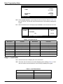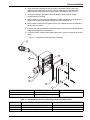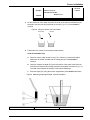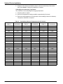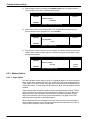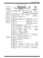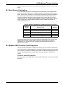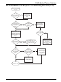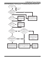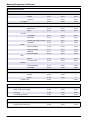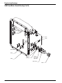
1
Catalog Number 3314
Sigma 950 Flow Meter
USER MANUAL
August 2009, Edition 7
© Hach Company, 2009. All rights reserved. Printed in the U.S.A.
Table of Contents
Section 1 Safety Precautions ........................................................................................................... 5
1.1 Use of Hazard Information ........................................................................................................... 5
1.1.1 Precautionary Labels .......................................................................................................... 5
1.2 Hazardous Locations ................................................................................................................... 6
1.3 Confined Space Entry .................................................................................................................. 6
1.4 FCC Requirements ...................................................................................................................... 7
1.5 Service Requirements.................................................................................................................. 8
Section 2 Specifications.................................................................................................................... 9
2.1 Factory Installed Options
........................................................................................................ 10
Section 3 Introduction ..................................................................................................................... 17
3.1 Measurement Capabilities ......................................................................................................... 17
3.2 Front Panel Features and Controls............................................................................................ 17
3.2.1 Power Indicator Light ........................................................................................................ 19
Section 4 Controller Installation .................................................................................................... 21
4.1 Unpacking the Instrument .......................................................................................................... 22
4.2 Choosing the Proper Site........................................................................................................... 22
4.3 Mounting Options....................................................................................................................... 22
4.3.1 Wall Mounting (Optional) .................................................................................................. 22
4.3.2 Suspension Harness Installation (Optional) ...................................................................... 23
4.3.3 Manhole Rung Hanger (Optional) ..................................................................................... 23
4.4 Installing the Power Supply........................................................................................................ 24
4.5 Interface Connector Descriptions............................................................................................... 25
4.6 12 VDC Connections ................................................................................................................. 25
4.7 Sampler...................................................................................................................................... 26
4.7.1 Sampler Connections........................................................................................................ 26
4.7.2 Sampler Programming ...................................................................................................... 26
4.8 Installation Requirements for CE Marked 950 Flow Meter Models............................................ 27
Section 5 Basic Programming Setup ........................................................................................... 29
5.1 Initial Power-Up of Meter ........................................................................................................... 29
5.2 Basic Programming.................................................................................................................... 29
Section 6 Sensor Installation ......................................................................................................... 37
6.1 Downlooking Ultrasonic Depth Sensor ...................................................................................... 37
6.1.1 Downlooking Ultrasonic Depth Sensor Connection .......................................................... 37
6.1.2 Downlooking Ultrasonic Depth Sensor Programming ....................................................... 37
6.1.3 Downlooking Ultrasonic Depth Sensor Calibration ........................................................... 38
6.1.3.1 Liquid Depth ............................................................................................................. 38
6.1.3.2 Sensor Height .......................................................................................................... 39
6.1.3.3 Setting the Invisible Range ...................................................................................... 39
6.2 In-Pipe Zero Deadband Ultrasonic Depth Sensor...................................................................... 40
6.2.2 Programming the In-Pipe Zero Deadband Ultrasonic Depth Sensor ................................ 40
6.2.3 Beam Angle ...................................................................................................................... 40
6.2.4 Calibrating the In-Pipe Zero Deadband Ultrasonic Depth Sensor..................................... 40
6.3 Submerged Area/Velocity Sensor.............................................................................................. 42
6.3.1 Bare Lead Sensor Cables ................................................................................................. 42
6.3.2 Junction Box Connection Procedure................................................................................. 42
6.3.3 Submerged Area/Velocity Sensor Programming .............................................................. 44
6.3.4 Submerged Area/Velocity Sensor Calibration................................................................... 44
6.4 Low Profile Velocity-Only Sensor............................................................................................... 45
6.4.1 Low Profile Velocity-Only (Low Profile) Sensor Connection ............................................. 45
6.4.2 Low Profile Velocity-Only Sensor Programming ............................................................... 45
6.4.3 Low Profile Velocity-Only Sensor Calibration.................................................................... 45
1
Table of Contents
6.5 Submerged Depth Only Sensor .................................................................................................46
6.5.1 Submerged Depth Only Sensor Connection .....................................................................46
6.5.2 Submerged Depth Only Sensor Programming ..................................................................46
6.5.3 Submerged Depth Only Sensor Calibration ......................................................................46
6.6 Bubbler .......................................................................................................................................48
6.6.1 Bubbler Connections .........................................................................................................48
6.6.1.1 Meter-End Cable Terminations.................................................................................49
6.6.1.2 Routing the Bubbler Line ..........................................................................................49
6.6.2 Bubbler Installation ............................................................................................................50
6.6.2.1 Installation Guidelines ..............................................................................................50
6.6.3 Depth Only and Bubbler Area/Velocity Calibration............................................................50
Section 7 Optional Device Installation .........................................................................................53
7.1 Rain Gauge ................................................................................................................................53
7.1.1 Rain Gauge Connection ....................................................................................................53
7.1.2 Rain Gauge Programming.................................................................................................53
7.2 pH Probe ....................................................................................................................................54
7.2.1 pH Probe Connection ........................................................................................................54
7.2.2 pH Probe Programming.....................................................................................................54
7.2.3 pH Probe Calibration .........................................................................................................54
7.3 ORP Probe .................................................................................................................................55
7.3.1 ORP Probe Connection .....................................................................................................55
7.3.2 ORP Programming ............................................................................................................55
7.3.3 ORP Preamplifier/Junction Box Calibration.......................................................................56
7.4 Dissolved Oxygen Probe............................................................................................................56
7.4.1 Dissolved Oxygen Probe Connection................................................................................56
7.4.2 Dissolved Oxygen Probe Programming ............................................................................56
7.4.3 Dissolved Oxygen Probe Temperature Programming.......................................................57
7.4.4 Dissolved Oxygen Probe Calibration.................................................................................57
7.5 Conductivity Probe .....................................................................................................................58
7.5.1 Conductivity Probe Connection .........................................................................................58
7.5.2 Conductivity Probe Programming......................................................................................58
7.5.3 Conductivity Temperature Programming...........................................................................58
7.5.4 Conductivity Probe Calibration ..........................................................................................59
Section 8 Communications Setup .................................................................................................61
8.1 RS232 Setup ..............................................................................................................................61
8.1.1 RS232 Connections...........................................................................................................61
8.1.2 RS232 Programming .........................................................................................................62
8.2 Modem .......................................................................................................................................63
8.2.1 Modem Connection ...........................................................................................................63
8.2.2 Modem Programming ........................................................................................................63
8.2.3 Modem Options .................................................................................................................64
8.2.3.1 Pager Option ............................................................................................................64
8.2.3.2 Reporting Devices ....................................................................................................65
8.2.3.3 Entering the Phone Number of the Remote Computer.............................................67
8.2.3.4 Choosing the Dial Method (Tone or Pulse) ..............................................................67
8.3 Analog Communications ............................................................................................................68
8.3.1 4–20 mA Output ................................................................................................................68
8.3.1.1 4–20 mA Connections ..............................................................................................68
8.3.1.2 Programming the 4–20 mA Output ..........................................................................68
8.3.1.3 Calibrating the 4–20 mA Output ...............................................................................69
8.3.2 Analog Inputs.....................................................................................................................70
8.3.2.1 Analog Voltage Inputs ..............................................................................................70
2
Table of Contents
8.3.2.2 Analog Voltage Inputs Programming ....................................................................... 71
8.4 Alarm Relays.............................................................................................................................. 72
8.4.1 Alarm Relay Connections ................................................................................................. 72
8.4.2 Alarm Relays Programming .............................................................................................. 73
8.4.2.1 Trouble Alarms......................................................................................................... 73
8.4.2.2 Set Point Alarms ...................................................................................................... 74
Section 9 Maintenance .................................................................................................................... 75
9.1 Routine Maintenance ................................................................................................................. 75
9.1.1 Calibration ......................................................................................................................... 75
9.1.2 Cleaning the Case ............................................................................................................ 75
9.1.3 Maintaining Desiccant Cartridges and Desiccant.............................................................. 76
9.1.3.1 Replacing the Desiccant .......................................................................................... 76
9.1.3.2 Rejuvenating the Desiccant ..................................................................................... 76
9.1.3.3 Maintaining the Hydrophobic Membrane ................................................................. 76
9.2 Upgrades, Repairs, General Maintenance................................................................................. 76
9.2.1 Internal Maintenance Items............................................................................................... 77
9.2.2 Removing the Front Panel ................................................................................................ 77
9.2.3 Re-Installing the Front Panel ............................................................................................ 78
9.3 Circuit Board Identification ......................................................................................................... 79
9.4 Fuse and Connector Locations .................................................................................................. 79
9.4.1 Fuse Removal and Inspection .......................................................................................... 81
9.4.2 Working with Wiring Connectors ....................................................................................... 82
9.5 Replacing the Internal Desiccant Module .................................................................................. 82
9.6 Replacing the Internal Case-Humidity Indicator Disc................................................................. 82
9.7 Memory Batteries....................................................................................................................... 83
Section 10 Contact Information for U.S.A. and Outside Europe ........................................... 85
Section 11 Contact information for Europe ................................................................................ 87
Appendix A Program Flow Charts ................................................................................................ 89
Appendix B Programming Features ............................................................................................. 95
Appendix C Primary Devices & Head Measurement Locations ........................................... 109
Appendix D Programming Worksheet ....................................................................................... 113
Appendix E SCADA-Modbus® System Guidelines ................................................................. 117
Appendix F Batteries and Chargers ........................................................................................... 133
Appendix G Troubleshooting
................................................................................................. 137
Appendix H Manning Roughness Coefficients ........................................................................ 143
Appendix I Engineering Drawings .............................................................................................. 145
3
Table of Contents
4
Section 1
Safety Precautions
Please read this entire manual before unpacking, setting up, or operating this instrument.
Pay particular attention to all danger and caution statements. Failure to do so could result in serious injury to the
operator or damage to the equipment.
Do not use or install this equipment in any manner other than that which is specified in this manual.
1.1 Use of Hazard Information
If multiple hazards exist, this manual will use the signal word (Danger, Caution, Note) corresponding to the
greatest hazard.
DANGER
Indicates a potentially or imminently hazardous situation which, if not avoided, could result in
death or serious injury.
CAUTION
Indicates a potentially hazardous situation that may result in minor or moderate injury.
NOTE
Information that requires special emphasis.
1.1.1 Precautionary Labels
Read all labels and tags attached to the instrument. Personal injury or damage to the instrument could occur if
not observed.
This symbol, if noted on the instrument, references the instruction manual for operation
and/or safety information.
Electrical equipment marked with this symbol may not be disposed of in European public disposal systems after 12
August of 2005. In conformity with European local and national regulations (EU Directive 2002/96/EC), European
electrical equipment users must now return old or end-of life equipment to the Producer for disposal at no charge to
the user.
Note: For return for recycling, please contact the equipment producer or supplier for instructions on how to return
end-of-life equipment, producer-supplied electrical accessories, and all auxiliary items for proper disposal.
This symbol, when noted on a product enclosure or barrier, indicates that a risk of electrical shock
and/or electrocution exists and indicates that only individuals qualified to work with hazardous voltages
should open the enclosure or remove the barrier.
This symbol, when noted on the product, identifies the location of a fuse or current limiting device.
This symbol, when noted on the product, indicates that the marked item can be hot and should not be
touched without care.
This symbol, when noted on the product, indicates the presence of devices sensitive to Electro-static
Discharge and indicates that care must be taken to prevent damage to them.
This symbol, when noted on the product, identifies a risk of chemical harm and indicates that only
individuals qualified and trained to work with chemicals should handle chemicals or perform
maintenance on chemical delivery systems associated with the equipment.
This symbol, if noted on the product, indicates the need for protective eye wear.
This symbol, when noted on the product, identifies the location of the connection for Protective Earth
(ground).
5
Safety Precautions
1.2 Hazardous Locations
The Sigma 950 Flow Meter is not approved for use in hazardous locations as defined in
the National Electrical Code.
DANGER
Although some Hach products are designed and certified for installation in
hazardous locations as defined by the National Electrical Code, many Hach
products are not suitable for use in hazardous locations. It is the responsibility of
the individuals who are installing the products in hazardous locations to determine
the acceptability of the product for the environment. Additionally, to ensure safety,
the installation of instrumentation in hazardous locations must be per the
manufacturer's control drawing specifications. Any modification to the
instrumentation or the installation is not recommended and may result in life
threatening injury and/or damage to facilities.
DANGER
Bien que certains produits Sigma soient conçus et certifiés pour être installés dans des
endroits dangereux tels que définis par le National Electric Code, de nombreux produits
Sigma ne conviennent pas pour de tels endroits. Il relève de la responsabilité des personnes
qui placent les produits dans des endroits dangereux de déterminer s'ils sont adaptés à cet
environnement. En outre, à des fins de sécurité, le placement de machines dans des endroits
dangereux doit s'effectuer dans le respect des consignes des schémas de contrôle du
fabricant. Toute modification apportée aux machines ou tout déplacement de celles-ci est
déconseillé, car susceptible de provoquer des accidents matériels et/ou corporels.
1.3 Confined Space Entry
The following information is provided to guide users of Sigma 950 Flow Meters on the
dangers and risks associated with entry into confined spaces.
DANGER
Additional training in Pre-Entry Testing, Ventilation, Entry Procedures,
Evacuation/Rescue Procedures and Safety Work Practices is necessary to ensure
against the loss of life in confined spaces.
DANGER
Pour éviter les accidents mortels dans les espaces confinés, il faut organiser des
formations supplémentaires dans les matières suivantes: Contrôle avant entrée,
Ventilation, Procédures d'entrée, Procédures d'évacuation et de secours et
Méthodes de travail sûres.
On April 15, 1993, OSHA's final ruling on CFR 1910.146, Permit Required Confined
Spaces, became law. This standard directly affects more than 250,000 industrial sites in
the United States and was created to protect the health and safety of workers in confined
spaces.
Definition of Confined Space
A Confined Space is any location or enclosure that presents or has the immediate
potential to present one or more of the following conditions:
6
•
An atmosphere with less than 19.5% or greater than 23.5% oxygen and/or more than
10 ppm Hydrogen Sulfide (H2S).
•
An atmosphere that may be flammable or explosive due to gases, vapors, mists,
dusts, or fibers.
Safety Precautions
•
Toxic materials which upon contact or inhalation, could result in injury, impairment of
health, or death.
Confined spaces are not designed for human occupancy. They have restricted entry and
contain known or potential hazards.
Examples of confined spaces include manholes, stacks, pipes, vats, switch vaults, and
other similar locations.
Standard safety procedures must always be followed prior to entry into confined spaces
and/or locations where hazardous gases, vapors, mists, dusts, or fibers may be present.
Before entering any confined space check with your employer for procedures related to
confined space entry.
1.4 FCC Requirements
1. The Federal Communications Commission (FCC) has established Rules which permit
this device to be directly connected to the telephone network. Standardized jacks are
used for these connections. This equipment should not be used on party lines or coin
lines.
2. If this device is malfunctioning, it may also be causing harm to the telephone network;
this device should be disconnected until the source of the problem can be determined
and until repair has been made. If this is not done, the telephone company may
temporarily disconnect service.
3. The telephone company may make changes in its technical operations and
procedures; if such changes affect the compatibility or use of this device, the
telephone company is required to give adequate notice of the changes.
4. If the telephone company requests information on what equipment is connected to
their lines, inform them of:
a. The telephone number that this unit is connected to,
b. The ringer equivalence number [1.4B]
c. The USOC jack required [RJ11C], and
d. The FCC Registration Number.
Items (b) and (d) are indicated on the label. The ringer equivalence number (REN) is
used to determine how many devices can be connected to your telephone line. In most
areas, the sum of the RENs of all devices on any one line should not exceed five. If too
many devices are attached, they may not ring properly.
Equipment Attachment Limitations Notice:
The Canadian Industry Canada label identifies certified equipment. This certification
means that the equipment meets certain telecommunications network protective,
operational and safety requirements. The Department does not guarantee the equipment
will operate to the user's satisfaction.
Before installing this equipment, users should ensure that it is permissible to be
connected to the facilities of the local telecommunications company. The equipment must
also be installed using an acceptable method of connection. In some cases, the
company's inside wiring associated with a single line individual service may be extended
by means of a certified connector assembly (telephone extension cord). The customer
should be aware that compliance with the above conditions may not prevent degradation
of service in some situations.
Repairs to certified equipment should be made by an authorized Canadian maintenance
facility designated by the supplier. Any repairs or alterations made by the user to this
equipment, or equipment malfunctions, may give the telecommunications company cause
to request the user to disconnect the equipment.
7
Safety Precautions
Users should ensure for their own protection that the electrical ground connections of the
power utility, telephone lines and internal metallic water pipe system, if present, are
connected together. This precaution may be particularly important in rural areas.
CAUTION
Users should not attempt to make such connections themselves, but should
contact the appropriate electric inspection authority, or electrician, as appropriate.
DANGER
Les utilisateurs ne doivent pas essayer d'établir eux-mêmes de telles connexions,
mais doivent contacter l'électricien ou l'organisme de vérification électrique
appropriée, selon le cas.
The Load Number (LN) assigned to each terminal device denotes the percentage of the
total load to be connected to a telephone loop which is used by the device, to prevent
overloading. The termination on a loop may consist of any combination of devices subject
only to the requirement that the total of the Load Numbers of all the devices does not
exceed 100.
1.5 Service Requirements
In the event of equipment malfunction, all repairs should be performed by the
manufacturer or an authorized agent. It is the responsibility of users requiring service to
report the need for service to the manufacturer, or to one of our authorized agents.
Service can be facilitated throughout our office (Section 10 on page 85).
8
Section 2
Specifications
Specifications are subject to change without notice.
General
Dimensions
34.3 H x 25.4 W x 24.1 cm D (13.5 x 10.0 x 9.5 in.)
Weight
5 kg (11 lb) not including power source
Enclosure
NEMA 4X, 6 with front cover open or closed
ABS, UV resistant
Temperature
Storage: -40 to 80°C (-40 to 176°F) Operating: -10 to 65.5°C (14 to 150°F)
Power Options
12Vdc supplied from one of:
7 A-Hr rechargeable gel lead-acid battery
4 A-Hr rechargeable Ni-Cad battery
Non-rechargeable alkaline lantern batteries (2 x 6VDC)
15Vdc supplied from one of:
100-120VAC input power supply
230VAC input power supply
Graphics Display
Back-lit liquid crystal display (LCD), auto-off when not in use (under battery operation).
8 line x 40 character in text mode, 60 x 240 pixels in graphics mode.
Keypad
21-position sealed-membrane switch with blinking green LED to indicate power on. Four “soft
keys,” functions defined by display.
Totalizers
8-digit resettable and 8-digit non-resettable software
Time Base Accuracy
± 0.007% per day
Measurement Modes
Flumes: Parshall, Palmer Bowlus, Leopold-Lagco, H, HL, HS, Trapezoidal
Weirs: V-notch (22.5 to 120 degrees), Compound V-Notch, Contracted/Non-Contracted
rectangular, ThelMar, Cipolletti
Manning Equation: Round, U, Rectangular and Trapezoidal Channels
Flow Nozzle: California Pipe
Head vs. Flow: Custom programmable curve of up to 99 points.
Level only: Inches, feet, centimeters, meters
Area Velocity: Level-area table, Circular pipe, U-shaped channel, Trapezoidal channel,
Rectangular channel
Power Equation: Q = K 1 H
n1
+ K2H
n2
Data Logging
"Smart" dynamic memory allocation automatically partitions memory to provide the maximum
logging time. No manual memory partitioning required.
Memory Mode: Either slate or wrap-around may be selected.
Data Points: Approximately 20,000 standard. Expandable up to 116,000 data points.
Daily statistics: Available for up to 32 days.
Recording Intervals: 1, 2, 3, 5, 6, 10, 12, 15, 20, 30, 60 minutes
Sampler Output
12 to 17 VDC pulse, 100 mA max at 500 ms duration
Communications
RS232 - up to 19,200 baud
Modem - 14400 bps., V.32 bis. V.42, MNP2-4 error correction. V.42 bis MNP5 data
compression. MNP 10-EC Cellular Protocol Pager
SCADA - Modbus communication protocol (standard) through RS232 or optional modem
CE Mark
CE - some 950 models (such as, 3248, 3522 and 2672) when used as detailed in manual
Section 2.8
CE - 230V AC-DC power adaptor and cETLus 115V AC-DC power adaptor (UL/CSA 61010-1
Safety Std.)
9
Specifications
2.1 Factory Installed Options
Integral pH/Temperature Meter (pH and ORP cannot be simultaneously measured)
Control/Logging
Field selectable to log pH/temperature independent of flow or in conjunction with flow; also
controls sample collection in response to value of low/high setpoints.
pH/Temperature Sensor
pH combo, 3/4" NPT-in-line, ryton, ASG V Flat 100 ohm KTD/GND in glass, DJ with porous
gel Ag/AgCI gel in Dynagan out, CE cable
pH Range
0 to 3 pH
Operating Temperature
0 to 80°C (0 to 176°F)
Dimensions
1.9 D x 15.24 cm L (0.75 x 6 in.) with 1.9 cm (0.75 in.) mpt cable end
Totalizers
6-digit non-resettable mechanical Units: ft³, gal, m³, liter, acre-ft
Pressure Rating
100 psi maximum
pH Response Time
5 seconds to 95% of full response
ORP Meter
Reading
86 ± 15 mV (25°C) (in pH 7.00 - saturated with Quinhydrone)
Slope
170 mV (25°C) (pH 4-7) (saturated with Quinhydrone)
Temperature Range
0 to 80°C (0 to 176°F)
Integral Dissolved Oxygen Meter
Control/Logging
Field selectable to log dissolved oxygen independent of flow or in conjunction with flow. Also
controls sample collection in response to value of low/high set points.
Measurement Method
Polargraphic
Sensor
Temperature compensated; impact resistant polypropylene body
Measurement Range
0 to 20 mg/L dissolved oxygen
Resolution
0.01 mg/L
Accuracy
±0.02 mg/L
Operating Temperature
0 to 50°C (32 to 122°F)
Dimensions
1.65 x 12.7 cm (0.65 x 5 in.) with 1.95 cm (0.75 in.) mpt cable end
Integral Conductivity Meter
10
Control/Logging
Field selectable to log conductivity independent of flow or in conjunction with flow. It also
controls sample collection in response to value of low/high set points.
Sensor
Temperature compensated; impact resistant polypropylene body
Measurement Range
0 to 100 mS/cm
Resolution
0.01 mS/cm or 1 mS/cm (user selectable)
Accuracy
±1% of reading + 0.05 mS/cm
Operating Temperature
0 to 50°C (32 to 122°F)
Dimensions
1.7 x 12.7 cm (0.67 x 5 in.) with 1.9 cm (0.75 in.) mpt cable end
Specifications
Rain Gauge Input
General Information
For use with Hach Tipping Bucket Rain Gauge.
Flow meter records rainfall data in 0.01 in. increments.
Analog Input Channels
General Information
Up to 7 additional data logging channels record data from external source(s)
Field assignable units
-4.5 to + 4.5 VDC, ± 0.5% full scale voltage accuracy and 0 to 20 mA, ± 0.2% full scale 4-20
mA accuracy with 200 ohm impedence
Alarm Relays
General Information
(4) 10 amp/120 Vac or 5 amp/250 Vac form C relays
User assignable for any internal or external data channel or event.
4–20 mA Output
General Information
2 output signals available
User assignable
Optically isolated
0.1 FS error
Maximum Resistive
Load
600 ohms
Output Voltage
24 VDC–no load
Insulation Voltage
Between flow meter and 4–20 mA output - 2500 Vac
Between the two 4–20 mA outputs - 1500 Vac
Communications
General Information
RS232 - up to 19,200 baud
Modem - 14400 bps., V.32 bis, V.42, MNP2-4 error correction. V.42 bis MNP5 data
compression. MNP 10-EC Cellular Protocol
Sensor Specifications
Pager
SCADA-Modbus® communication protocol (standard) via RS232 or optional modem
Bubbler Sensor
Accuracy
±0.003 m (0.011 ft) linearity and hysteresis at 22 °C (72 °F), from 0.01 to 11.75 ft
Range
0.003 to 3.6 m (0.01 to 11.75 ft)
Ambient Operating
Temperature
–18 to 63 °C (0 to 145 °F)
Compensated
Temperature
0 to 59 degrees C (32 to 138 degrees F)
Temperature Error
±0.0003. ft./°F (maximum error within compensated temperature range per degree of change)
Air Intakes
Bubble source and reference port—desiccant protected. Fittings provided for remote intakes.
Filter
10 micron on bubble source intake
Line Purge
Bubble line is high pressure purged at programmed intervals or in manual mode on demand.
Line Size
0.32 cm (1/8 in.) ID standard
Line Lengths
160 m (500 ft) maximum
11
Specifications
Submerged Depth Only Sensor
Accuracy
+0.1% full scale (Non-linearity and dysteresis)
Range
2.5 psi; 0.01 to 1.75 m (0.04 to 5.75 ft)
Ambient Operating
Temperature
0 to 71 °C (32 to 160 °F)
Temperature Error
2.5 psi: 0.04 to 5.75 ft. +/-0.006 ft./ °F (maximum error within compensated temperature
range per degree of change)
Air Intake
Atmospheric pressure reference is desiccant protected
Material
316 stainless steel body with titanium diaphragm
Cable
4-conductor polyurethane sensor cable with air vent
Cable Length
7.6 m (25 ft) standard; 76 m (250 ft) maximum
Dimensions
2.54 x 17.2 cm (1 x 6.75 in.)
Probe Frontal Area: 0.875 in. (squared)
Weight
0.7 kg (1.5 lbs)
Downlooking Ultrasonic Depth Sensor–50 kHz
Accuracy
Range
12
1 to 10 ft. ± 0.01 ft. (± 0.003 m) (at 22 °C (72 °F), still air, 40 to 70% relative humidity)
Maximum distance from sensor to liquid 9.1 m (30 ft)
Minimum distance from sensor to liquid 38.1 cm (15 in.)
Span
0 to 8.84 m (0 to 29 ft.)
Sensor Certification
USA: Class I, Zone I, Groups A, B, C, D
Canada: Class I, Division I, Groups A, B, C, D, Class II, Division I, Groups E, F, G
Ambient Operating
Temperature
-18 to 60°C (0 to 140°F)
Temperature Error
± 0.000047 ft./°F (maximum error within compensated temperature range per degree of
change)
Resolution
0.0011 ft.
Material
PVC housing with Buna-N acoustic window
Cable
4-conductor with integral stainless steel support cable
Cable Length
7.6 m (25 ft.) standard (custom lengths are available)
Crystal Specification
50 kHz, 11.5° included beam angle
Dimensions
(transducer only)
9.5 cm H x 7 cm D (3.75 in. H x 2.75 in. D)
Weight
0.7 kg (1.5 lbs)
Specifications
Downlooking Ultrasonic Depth Sensor–75 kHz
Accuracy
Range
1 to 10 ft ±0.01 ft (±0.003 m) at 22°C (72 °F), still air, 40–70% relative humidity.
Maximum distance from sensor to liquid 3.3 m (10.8 ft)
Minimum distance from sensor to liquid 23 cm (9 in.)
Span
0 to 4.57 m (0 to 15 ft)
Sensor Certification
USA: Class I, Zone I, Groups A, B, C, D
Canada: Class I, Division I, Groups A, B, C, D, Class II, Division I, Groups E, F, G
Ambient Operating
Temperature
–18 to 60°C (0 to 140°F)
Temperature Error
±0.000047 ft/°F (maximum error within compensated temperature range—per degree of
change.)
Resolution
0.0011 ft
Material
PVC housing with Buna-N acoustical window
Cable
4-conductor with integral stainless steel support cable
Cable Length
7.6 m (25 ft) standard (custom lengths are available)
Crystal Specification
5° beam angle with horn
Dimensions
12.7 (H) x 5.7 cm (D) (5.0 x 2.25 in.)
Weight
0.7 kg (1.5 lb)
In-Pipe Zero Deadband Ultrasonic Depth Sensor –75 kHz
Accuracy
0.038 to 2.4 m ±0.003 m (0.125 to 8 ft. ± 0.01 ft.) (at 22°C (72°F), still air, 40 to 70% relative
humidity)
Range
Distance from sensor to liquid: 0 to 2.4 m (0 to 8 ft)
Span
0.038 to 4.57 m (0.125 to 15 ft)
Sensor Certification
USA: Class I, Zone I, Groups A, B, C, D
Canada: Class I, Division I, Groups A, B, C, D, Class II, Division I, Groups E, F, G
Resolution
0.019 cm (0.0075 in.)
Ambient Operating
Temperature
-18 to 60°C (0.04 to 140°F)
Temperature Error
±0.00005 m/°C (±0.0001 ft./°F) (maximum error within compensated temperature range
per degree of change)
Material
Stat-Kon A-E ABS Plastic
Cable
4-conductor
Cable Length
7.6 m (25 ft) standard, custom lengths up to 305 m (1000 feet) using RS485 two wire remote
sensor option
Crystal Specification
7° beam angle
Dimensions
(transducer only)
4.44 cm (1.75 in.) maximum diameter, 31.5 cm (12.4 in.) long
Mounting
Dedicated Mounting Rings, Permanent Mounting Bracket (installs directly to pipe wall),
Adjustable Mounting Band Kit.
Connection
Bare lead connection through 3658 junction box or quick connect.
13
Specifications
Low-Profile Velocity-Only Sensor
Accuracy
±2% of reading; Zero Stability: <0.52 cm/s (± 0.05 ft/s)
Range
-1.52 to 6.1 ms (-5 to +20 ft/s)
Resolution
0.3 cms (0.01 ft/s)
Response Time
4.8 seconds
Profile Time
4.8 seconds
Dimensions
Length: 6.86 cm (2.7 in.)
Width: 3.81 cm (1.5 in.)
Height: 1.12 cm (0.44 in.)
Cable
Urethane Jacket, (2x) RG174U Coax Cables, (4x) #22 AWG Copper Stranded
Cable Length
7.6 m (25 ft) standard (custom cable lengths to 76 m (250 ft) are available)
Submerged Area/Velocity Sensor
Velocity Measurement
Method
Doppler Ultrasound Twin 1 MHz piezoelectric crystals
Accuracy
±2% of reading
Recommended Range
–1.52 to 6.1 m/s (-5 to +20 ft/s)
Zero Stability
<0.015 m/s (<0.05 ft/s)
Typical Minimum Depth 2 cm (0.8 in.)
Depth Measurement
14
Method
Pressure Transducer with stainless steel diaphragm
Material
Polyurethane body, 316 series stainless steel diaphragm
Accuracy (static1)
±0.16% full scale ±1.5% of reading at constant temp (±2.5°C)
±0.20% full scale ±1.75% of reading from 0 to 30°C (32 to 86°F)
±0.25% full scale ±2.1% of reading from 0 to 70°C (32 to 158°F)
Standard Depth Range
0 to 3 m (0 to 10 ft.)
Extended Range
0 to 9 m (0 to 30 ft.)
Maximum Allowable
Depth
Standard: 10.5 m (34.5 ft.)
Extended: 31.5 m (103.5 ft.)
Operating Temperature
Range
32 to 160°F (0 to 71°C)
Compensated
Temperature Range
32 to 86°F (0 to 30°C)
Temperature Error
0.005 to 3.5 m ±0.0022 m/°C (0.018 to 11.5 ft ±0.004 ft/°F)
0.005 to 10.5 m ±0.006 m/°C (0.018 to 34.6 ft ±0.012 ft/°F)
(maximum error w/in compensated temperature range - per degree of change)
Velocity Induced Error
on Depth
Compensated based on pipe geometry and flow velocity
Air Intake
Atmospheric pressure reference is desiccant protected
Specifications
Bubbler Area / Velocity Sensor
Depth Measurement
Method
Doppler principle / pressure transducer
Range
0.003 to 3.6 m (0.01 to 11.75 ft.)
Accuracy
0.01 to 11.75 ft. ±0.011 ft. (0.033 m)
(linearity and hysteresis at 22°C (72°F))
Ambient Operating
Temperature
-18 to 63°C (0 to 145°F)
Compensated
Temperature Range
0 to 59°C (32 to 136°F)
Temperature Error
±0.0003 ft./°F (maximum error within
compensated temperature range per
degree of change)
Air Intakes
Bubble source and reference port desiccant protected.
Fittings provided for remote intakes.
Filters
10 micron on bubble source intake
Line Purge
Bubble line is high pressure purged at programmed intervals, or in manual mode on demand.
Velocity Measurement
1 For
Method
Doppler ultrasonic
Transducer Type
Twin 1 MHz piezoelectric crystals
Range
-1.52 to 6.10 m/s (-5 to 20 ft/s)
Zero Stability
< 0.015 m/s (0.05 ft/s)
Accuracy
±2% of reading
Typical Minimum Depth
2 cm (0.8 in.)
Operating Temperature
-18 to 60°C (0 to 140°F)
Dimensions
1.12 x 3.81 x 6.86 cm
(0.44 x 1.5 x 2.7 in.)
temperatures above 40°C (104°F) add ± 0.3 cm/°C (0.03 in./°F)
15
Specifications
16
Section 3
Introduction
3.1 Measurement Capabilities
The 950 Flow Meter is a portable flow meter that is completely self-contained. With its
rugged construction, the meter is completely sealed—even with the door open.
Conforming to NEMA 4X, 6 standards, the meter also withstands submersion and
corrosive gases—again, with its door open. As a result, access to the meter’s keypad is
no problem in manholes, rain, and other harsh weather conditions.
The 950 Flow Meter is suitable for measuring and recording flow in open channels, full
pipes, and surcharged lines. The 950 Flow Meter is most often used to measure flow in
conjunction with a primary measuring device (flume, weir, pipe, etc.) that has a known
level-to-flow relationship. The 950 Flow Meter directly measures the level of liquid in a
channel that is contributing to flow (referred to as “head”) and calculates the flow rate
based on the head-to-flow relationship of the primary device.
The flow meter can also measure the average velocity of the flow stream using a
submerged Doppler sensor and calculate flow based on the current depth and the
Continuity Equation: Wetted Area × Velocity = Flow.
In addition to its extensive data logging capabilities, the 950 Flow Meter is capable of
enabling a sampler, pacing a sampler, controlling external devices with four Normally
Open/Normally Closed relays, and controlling external devices with two 4–20 mA current
outputs.
Communication capabilities include a standard RS232 port and an optional on-board
modem used for remote data transfer, remote programming, and updating internal
embedded programs using Flash Memory technology (RS232 only). The 950 Flow Meter
also provides SCADA Communication Interface functionality using the Modbus® ASCII
protocol. This software protocol communicates with the instrument via an RS232
connection.
Using Hach’s integrated sewer system management software, users can download,
remotely program, and conduct other data manipulation via RS232 connection or the
optional modem.
3.2 Front Panel Features and Controls
The 950 Flow Meter case has several unique features, all designed to simplify
installation, operation, and maintenance.
The instrument front cover protects the panel controls and display window while providing
a clear view of the flow meter status on the display. The cover also contains two lockable
latches which can be secured with a padlock(s) for security. While a software lock can be
programmed to keep unauthorized personnel from operating the keypad, the front cover
locking ability provides added security against tampering.
The cover perimeter contains a gasket seal to keep moisture and dirt from entering the
front panel area. This seal is not required to maintain the NEMA 4X,6 rating of the case.
17
Introduction
Figure 1 950 Flow Meter Front Panel
Item #
The menu bar appears in a black band on the top edge of the display. The upper left corner of the
menu bar shows the time and date. The upper right corner shows the name of the current menu.
1
Menu bar
2
Display
The 950 Flow Meter liquid crystal display (LCD) works in conjunction with the four soft keys as a guide
through all programming steps. The display also provides other useful information as described below.
Soft keys
The soft keys are the blank, white keys located to the left and right of the display. The function of each
key is according to the appearance of the display. If no function is shown for a specific key, that key is
not currently needed. The soft key labels appear on the display and point (with a straight line) to the
proper soft key to push for that action.
In some cases during a programming step you will be asked to pick an item from a list. The soft keys
on the right side of the display will change to display “up” and “down” arrows. This allows you to scroll
up and down the list of choices. When the desired choice is highlighted, press the SELECT soft key to
choose that item.
Status bar
The appearance of the status bar changes depending upon the function being performed. The lower
left corner of the status bar indicates whether a program is Complete, Running, Halted, or Ready To
Start. It will disappear if it is not needed during a programming step. The lower right corner displays
system alarm conditions, such as low memory battery, clogged bubbler line, etc. For a list of possible
alarms see Alarm Relays on page 72.
The status bar also lists valid choices when entering certain programming information. For example,
when selecting level measurement units in the Level Units menu, the status bar indicates the valid
choices: cm, ft, in., or m.
Humidity
Indicator
The Internal Humidity Indicator changes from blue to pink when the humidity inside the case exceeds
60 percent. An internal desiccant module absorbs any humidity that may have been trapped in the
case during final assembly. Under normal operating conditions, this desiccant provides long-term
protection against condensed moisture inside the case.
Replace the internal desiccant module only if the indicator turns pink. (See Replacing the Internal
Desiccant Module on page 82).
3
4
5
18
Description Function
Introduction
Mechanical
Totalizer
Option
An optional six-digit non-resettable mechanical totalizer is available for the flow meter. Located below
the Humidity Indicator, the totalizer indicates total flow and supplements the internal software totalizers
(one resettable and one non-resettable) that are configured during programming.
The totalizer can be configured for all conditions and installations because flow units and scaling are
selectable. To select flow and scaling factors for the mechanical and internal software totalizers see
Flow Totalizer on page 103.
To obtain the total flow for any period of time, record the number at the start of the time period,
subtract it from the number at the end of the period, and then multiply the difference by the scaling
factor.
7
Display
Button
The Display push-button is located on the upper right side of the case. It allows you to read the display
without opening the cover.
The 950 Flow Meter is optimized for portable (battery-powered) use. Its unique power saving modes
conserve battery resources by putting the meter to “sleep” during any period of inactivity.
During battery operation or ac power with the screen saver enabled, pressing the Display push-button
will “wake up” the flow meter and cause it to turn on the display. The Status Screen is the first screen
displayed. Another press of the button causes the display to show additional status information, if
necessary. Continuing to press the Display push-button will return you to the initial Status Screen after
all information has been shown.
After three minutes of inactivity, the display goes blank to conserve battery power.
8
Soft Keys
See item #3.
9
Function
Keys
The white keys located just above the numeric keys are function keys that are used often while
operating the flow meter. These functions are dedicated keys to allow quick access.
Main Menu: This is the program starting point. Press the Main Menu key at any time during
programming to return to the Main Menu Screen. The current action is cancelled if changes are not yet
accepted.
Level Adjust: Adjust the flow meter to match the current head (or level contributing flow) in the
channel.
Run/Stop: Run (or resume) a program. Stops a currently running program.
10
Numeric
Keypad
The numeric keypad is located below the function keys. It consists of the digits 0 through 9, a +/- key,
and a decimal key.
11
Power
On/Off
6
To turn the flow meter power on/off use the ON and OFF keys.
3.2.1 Power Indicator Light
When the unit is turned on, a green light located next to the ON key flashes. This does
not indicate that a program is running but indicates that the unit has power because
under some conditions (battery operation or Screen Saver mode), the display may
automatically turn off to conserve battery power.
See Screen Saver Mode on page 105 for details on battery operation and the Screen
Saver feature.
19
Introduction
20
Section 4
Controller Installation
DANGER
Some of the following manual sections contain information in the form of
warnings, cautions and notes that require special attention. Read and follow these
instructions carefully to avoid personal injury and damage to the instrument. Only
personnel qualified to do so, should conduct the installation/maintenance tasks
described in this portion of the manual.
DANGER
Certains des chapitres suivants de ce mode d’emploi contiennent des informations
sous la forme d’avertissements, messages de prudence et notes qui demandent
une attention particulière. Lire et suivre ces instructions attentivement pour éviter
les risques de blessures des personnes et de détérioration de l’appareil. Les
tâches d’installation et d’entretien décrites dans cette partie du mode d’emploi
doivent être seulement effectuées par le personnel qualifié pour le faire.
PELIGRO
Algunos de los capítulos del manual que presentamos contienen información muy
importante en forma de alertas, notas y precauciones a tomar. Lea y siga
cuidadosamente estas instrucciones a fin de evitar accidentes personales y daños
al instrumento. Las tareas de instalación y mantenimiento descritas en la presente
sección deberán ser efectuadas únicamente por personas debidamente
cualificadas.
GEFAHR
Einige der folgenden Abschnitte dieses Handbuchs enthalten Informationen in
Form von Warnungen, Vorsichtsmaßnahmen oder Anmerkungen, die besonders
beachtet werden müssen. Lesen und befolgen Sie diese Instruktionen
aufmerksam, um Verletzungen von Personen oder Schäden am Gerät zu
vermeiden. In diesem Abschnitt beschriebene Installations- und
Wartungsaufgaben dürfen nur von qualifiziertem Personal durchgeführt werden.
PERICOLO
Alcune parti di questo manuale contengono informazioni sotto forma
d’avvertimenti, di precauzioni e di osservazioni le quali richiedono una particolare
attenzione. La preghiamo di leggere attentivamente e di rispettare quelle istruzioni
per evitare ogni ferita corporale e danneggiamento della macchina. Solo gli
operatori qualificati per l’uso di questa macchina sono autorizzati ad effettuare le
operazioni di manutenzione descritte in questa parte del manuale.
DANGER
This instrument should be installed by qualified technical personnel to ensure
adherence to all applicable electrical codes.
DANGER
Cet appareil doit être installé par du personnel technique qualifié, afin d'assurer le
respect de toutes les normes applicables d'électricité.
Capped, watertight connectors for external devices are located along the left side of the
case. Level sensor inputs and accessories are located along the right side of the case.
A recessed pocket for installing the flow meter power supply is located at the top rear of
the case.
21
Controller Installation
4.1 Unpacking the Instrument
Remove the 950 Flow Meter from its shipping carton and inspect it for any visible
damage. Contact Hach Customer Service at 1-800-368-2723 if any items are missing or
damaged.
4.2 Choosing the Proper Site
The accuracy of your flow measurements greatly depends on the suitability of your
monitoring site. Select sites that have normalized flow and minimal turbulence.
Turbulence can make it difficult to detect an average velocity in the flow stream.
Obstructions, vertical drops, pipe bends, and elbows can create turbulence and affect the
accuracy of your measurements. Table 1 contains suggestions for preventing turbulence.
Table 1 Suggestions for Preventing Turbulence
Site Condition
Suggested Remedy
Outfalls
Place the sensor in at least ten times the maximum expected level upstream of the outfall.
Vertical drops in the
channel floor
Place the sensor in at least ten times the maximum expected level upstream of the vertical drop.
Elbows, sharp turns,
and “Y” connections
Place the sensor in at least ten times the maximum expected level upstream of the impediment.
Place the sensor in at least ten times the maximum expected level downstream of the vertical drop.
Place the sensor in at least ten times the maximum expected level downstream of the impediment.
4.3 Mounting Options
4.3.1 Wall Mounting (Optional)
Wall mounting the 950 Flow Meter requires the optional Wall Mounting Bracket (P/N.
2743). This bracket provides stable, secure mounting for the flow meter and provides
clearance for removing the power supply while the unit is installed. Connect the flow
meter with four ¼-20 screws (provided) using the four threaded inserts on the back of the
case. (See Figure 2).
22
Controller Installation
Figure 2 Wall Mounting Bracket
4.3.2 Suspension Harness Installation (Optional)
Use the optional Suspension Harness (P/N 2889) to suspend the flow meter in a manhole
or similar site. The suspension harness has two captive ¼-20 S.S. mounting screws
attached to the top of two threaded inserts on the back of the flow meter.
A stainless steel clip is also provided on top of the harness for mounting to an Instrument
Support Bracket (P/N 5713000) or similar support.
When suspending the flow meter, the Suspension Harness utilizes only the top two
threaded mounting inserts, leaving the bottom two free. Do not use the bottom inserts
for suspending any additional equipment. The inserts are designed to support only the
weight of a 950 Flow Meter and will not adequately support additional weight.
4.3.3 Manhole Rung Hanger (Optional)
The Manhole Rung Hanger (P/N 3533) is a convenient way to hang the 950 Flow Meter
from a manhole ladder rung. Constructed of 304 Stainless Steel, it makes a temporary
mounting as secure as a permanent one.
The Manhole Rung Hanger has two captive thumb screws for securing the bracket to the
top two threaded inserts on the 950 Flow Meter. The Manhole Rung Hanger also has a
spring loaded handle that secures the Hanger over a rung of up to 1¾ in. (4.4 cm) in
diameter.
When suspending the flow meter, the Manhole Rung Hanger utilizes only the top two
threaded mounting inserts, leaving the bottom two inserts free. Do not use the bottom
inserts for suspending any additional equipment. The inserts are designed to support
only the weight of a 950 Flow Meter and will not adequately support additional weight.
(See Figure 3 on page 24).
23
Controller Installation
Figure 3 Manhole Rung Hanger
1
2
1
Place over ladder rung.
2
Connect bottom inserts to meter.
4.4 Installing the Power Supply
The 950 Flow Meter is designed to accept either the manufacturer’s 12 VDC battery pack
or ac power converter.
1. Place the power supply on the back of the flow meter. (See Figure 4).
2. Pull the two rubber hold-down clamps up and over the clips on each end of the power
supply.
3. Connect the power supply connector to the port labeled 12 VDC on the top left side
of the case.
Figure 4 Power Supply and Interface Connectors
1
3
2
12 VDC
4
RS232
5
Sampler
1
Power Supply
3
12 VDC Port
2
Rubber Hold-down Clamp
4
RS232 Port
24
5
Sampler Port
Controller Installation
4.5 Interface Connector Descriptions
Note: All interface receptacles are covered with push-on caps. These caps are designed to protect
the connector pins from dirt and moisture and should be attached to any receptacle not in use.
The interface connector ports are located on the left side of the flow meter case. The 950
Flow Meter comes standard with three interface ports.
•
12 VDC (Power Input)
•
RS232 (Serial Communications Port)—(See section 8.1 on page 61 for connection
and programming details).
•
Sampler (Automatic Liquid Sampler Control)
In addition, the flow meter can be connected to a wide variety of optional peripheral
devices:
•
Rain Gauge (section 7.1 on page 53)
•
Modem (section 8.2.1 on page 63)
•
pH (section 7.2 on page 54)
•
Analog Inputs (section 8.3.2 on page 70)
•
ORP (section 7.3 on page 55)
•
Alarm Relays (section 8.4.1 on page 72)
•
Dissolved Oxygen (section 7.4 on page 56)
•
4–20 mA Current Loop(section 8.3.1 on page 68)
•
Conductivity (section 7.5 on page 58)
One or a combination of up to three sensors can be connected to the 950 Flow Meter,
depending on the system configuration.
•
Downlook Ultrasonic Depth Sensor (section 6.1 on page 37)
•
In-Pipe Zero Deadband Ultrasonic Depth Sensor (section 6.2
on page 40)
•
Submerged Area/Velocity Sensor (section 6.3 on page 42)
•
Low Profile Velocity Only Sensor (section 6.4 on page 45)
•
Submerged Depth Only Sensor (section 6.5 on page 46)
•
Bubbler Depth or Bubbler Area/Velocity Sensor (section 6.6
on page 48)
4.6 12 VDC Connections
This connection supplies power to the flow meter. Power sources include a battery
(Ni-Cad or Lead Acid), an ac power pack, or an external source such as a deep-cycle
marine battery or vehicle cigarette lighter connection. Refer to Batteries and Chargers on
page 133 for more information.
Although the 950 Flow Meter will operate on any attached 12 VDC power supply, the
instrument will assume it is battery operated if it detects a less than 14.2 VDC input and
will assume it is operating on an ac power converter if it detects a greater than 14.2 VDC
input.
Table 2 12 VDC Connector Pin Assignments
Pin
Signal Description
A
Ground
B
12 to 17 VDC, unregulated
25
Controller Installation
4.7 Sampler
4.7.1 Sampler Connections
The sampler interface receptacle is used to connect a wastewater sampler to the 950
Flow Meter.
Table 3 Sampler Connector Pin Assignments
Pin Signal Description
Wire Color
12 VDC (w/battery)
to 17 VDC pulse
(w/ac power pack)
500 mA max.
yellow
Used in with Pin B to signal a sampler that a pre-determined
amount of flow has accumulated with a 500 ms pulse.
12 VDC (w/battery)
to 17 VDC pulse
(w/ac power pack)
Used to “wake up” a waste water sampler when a set point
condition is met so that it can begin its sampling program.
Configure the flow meter for this pin in
Set Point Sampling on page 105.
Used in conjunction with Pin B, this line is normally allowed to
float and is switched to ground (by transistor) for the entire
period that the set point condition exists.
24 VDC (max) at
100 mA (max)
12 VDC (input only)
orange
B
ground
brown
C
flow pulse output
D
sampler start
black
E
event input
red
bottle number input
Rating
Pin A may receive power from an external device, 500 mA
max load.
Pin B provides the ground line that is used in conjunction with
the other signals on the connector.
A
F
Purpose
green
Received from a waste water sampler and indicates that a
sample has been collected. “Sample Taken” information will
appear in the data printout when downloaded.
N/A
Received from a waste water sampler and used in conjunction
with the Event Input signal. It tells the flow meter which bottle
was used when a sample was taken. “Sample Times and
Dates” information will appear in the data printout when
downloaded.
N/A
Cable Required for Sampler Connections
•
Multi-Purpose Half Cable Assembly, 3.0 m (10 ft), 6-pin connector on one end, tinned
wire leads on the other end (P/N 941) or
•
Multi-Purpose Full Cable Assembly, 3.0 m (10 ft), 6-pin connector on both ends (P/N
940).
•
Cables with 7.6 m (25 ft) lengths and custom sizes are also available.
4.7.2 Sampler Programming
1. From the Main Menu, select SETUP>MODIFY SELECTED ITEMS.
2. Scroll down and highlight SAMPLER PACING using the up and down arrow soft keys.
Press SELECT to continue.
3. Enable Sampler pacing using the CHANGE CHOICE soft key. Press ACCEPT to
continue.
4. Set the Sampler Pacing using the numeric keypad and Change Units using the
CHANGE UNITS soft key. The 950 Flow Meter will output one
12 VDC pulse each time the specified amount of flow has occurred.
5. Press ACCEPT.
26
Controller Installation
4.8 Installation Requirements for CE Marked 950 Flow Meter Models
Sigma 950 Flow Meters bearing a CE mark have special use and installation
requirements that are subject to the European Union’s Notified Body use limitations as
indicated below.
Only the 950 flow meter models, part numbers and options listed below are approved for
use in the EU under Hach’s CE marking scope:
Description
Catalog
Number
950 Combination Flow Meter with both AV + Bubbler Sensors
950 Flow Meter with AV Sensors only
950 Flow Meter with Bubbler Sensors only
AV Sensor Options (xx-xxx = depth range, fill option and cable length)
Bubbler Sensor Options (xxx = cable lengths)
3248
3522
2672
770xx-xxx
88007-xxx
pH Sensors with 7.6 m / 25 ft cable length
3328
pH Sensors with 15.2 m / 50 ft cable length
5172
4-20mA output option
12VDC Battery Option
230V 50Hz Battery Eliminator with Continental EU plug
230V 50Hz Battery Eliminator with UK plug
230V 50Hz Battery Eliminator with Italian plug
2684
1414
5721400
6244500
6244600
The use and location restrictions below apply:
•
The Sigma 950 Flow Meter is approved for use in the EU only when placed
underground in sewers, drain pipes and similar underground locations.
•
The 950 Flow Meter shall be connected only to an AC Mains source that is dedicated
to underground service. The mains service must not feed any residential locations.
If the 950 Flow Meter is operated in areas where high levels of RF energy or severe
electrical transients are present, performance-related problems can result from
electromagnetic interference. These conditions are not expected to be present in the
types of underground locations indicated above for the 950 Flow Meter use model.
27
Controller Installation
28
Section 5
Basic Programming Setup
5.1 Initial Power-Up of Meter
After power is applied, the flow meter performs a complete diagnostic self-test and
displays the menu shown when the unit was last turned off. The Main Menu is the starting
point for all programming operations. The Main Menu offers four choices:
•
Setup—Basic programming
•
Status—Lists all currently measured readings
•
Display Data—Shows graphs and tables of logged data
(See Displaying Data on page 95)
•
Options—Advanced programming
Regardless of the current menu displayed, pressing the Main Menu function key will bring
up the Main Menu screen.
Setup and Option functions lead to sub-menus which configure the basic and advanced
features of the flow meter. Refer to the 950 Flow Meter Basic Programming Setup on
page 87. The Display Data and Status lead to sub-menus which provide information only.
Press the STATUS soft key to display any data channels that have enabled logging (flow,
pH, temp., etc.).
11:00 AM 21 - APR - 01
DISPLAY DATA
OPTIONS
* Main Menu*
SETUP
STATUS
READY TO START
5.2 Basic Programming
Note: To make changes to the program entries after the basic programming setup, press the
MAIN MENU key and select SETUP>MODIFY SELECTED ITEMS. Highlight the program
entry using the up and down arrow soft keys.
Basic programming setup must be performed, in its entirety, after the instrument is
installed. Refer to the 950 Flow Meter Basic Programming Setup on page 87 for more
information.
The basic program setup will modify all items: flow units, primary devices, program lock,
sampler pacing, site ID, velocity direction, velocity units, velocity cutoff/velocity default.
Note: Velocity features will only display when using a 950 area/velocity flow meter.
Step 1 - Setup
1-A. Press SETUP from the Main Menu to prepare the 950 Flow Meter
for use.
1-B. Press MODIFY ALL ITEMS and press ACCEPT to begin setting up the flow units.
Step 2 - Flow Units
Note: Different flow units can be selected in the Sampler Pacing programming section (see Sampler
Pacing on page 32).
2-A. From the Modify All Items screen, highlight Flow Units using the UP and DOWN
keys. Press the SELECT soft key to continue.
29
Basic Programming Setup
11:00 AM 21 - APR - 01
* Main Menu*
LOGIN
MODIFY
ALL ITEMS
REVIEW ALL
ITEMS
MODIFY
SELECTED
ITEMS
READY TO START
2-B. Press CHANGE CHOICE to cycle through the flow unit choices. Refer to Table 4 for
flow unit choices. The flow unit will be used whenever a flow reading is displayed or
logged.
2-C. When the desired choice is displayed press ACCEPT to continue and set level units.
11:00 AM 21 - APR - 01
FLOW UNITS
CHANGE
CHOICE
ACCEPT
FLOW UNITS
mdg
CANCEL
SELECT APPROPRIATE UNITS
Table 4 Flow Unit Choices
Abbreviation
Flow Unit
Abbreviation
Flow Units
gps
Gallons per second
cfs
Cubic feet per second
gpm
Gallons per minute
cfm
Cubic feet per minute
gph
Gallons per hour
cfh
Cubic feet per hour
lps
Liters per second
cfd
Cubic feet per day
lpm
Liters per minute
cms
Cubic meters per second
lph
Liters per hour
cmm
Cubic meters per minute
mgd
Million gallons per day
cmh
Cubic meters per hour
afd
Acre-feet per day
cmd
Cubic meters per day
Step 3 - Level Units
3-A. Next the flow meter will display the Level Units screen.
3-B. Select the units of measure to use when displaying level readings (Table 5). Level
units of measure are used whenever a level reading is displayed or logged.
Table 5 Level Units Choices
30
Abbreviation
Level Unit
in.
inches
ft
feet
cm
centimeters
M
meters
Basic Programming Setup
3-C. Press CHANGE CHOICE to cycle through each of the level unit choices. Press
ACCEPT to continue to primary device setup.
Step 4 - Primary Device
Note: Selecting the appropriate primary device is critical for proper flow rate calculations.
4-A. Next, the flow meter will display the Primary Device screen.
4-B. Select the desired primary device, enter the calculation method, shape, and pipe
diameter for that primary device.
4-C. Press CHANGE CHOICE to cycle through the primary device choices (see Table 6,
Table 7, Table 8, and Table 9). Show the size and details required for each. Press
ACCEPT to continue to Program Lock.
11:00 AM 21 - APR - 01
PRIMARY DEVICE
CHANGE
CHOICE
ACCEPT
PRIMARY DEVICE:
WEIR
SELECT PRIMARY DEVICE
Table 6 Primary Device Choices
Primary Device
Description
None—Level Only No primary device installed. Level measurement only.
Weir
Compound, Cipolletti, Contracted rectangular, Non-contracted rectangular, ThelMar, V-Notch (22.5-120°),
Compound V-Notch (See Table 7)
Flume
Parshall, Trapezoidal, H-type, HL-type, HS-type, Leopold-Lagco, Palmer Bowlus (See Table 8)
Nozzle
California pipe
Power Equation
Head vs. Flow
n1
Q = K 1 H + K 2 H n2
K1 (0–9999.99), K2 (+/- 0–9999.99), n1 and n2 (1–9.99)
Two independent user–entered look up tables of up to 99 points each
Enter up to two tables of up to 100 user-defined head vs. flow points.
Head: 0–99.99 in feet or centimeters Flow: 0–99999.99 in any desired units
Enter variables K1, K2, n1 and n2
Rectangular channel, U-shaped, trapezoidal channel or Circular pipe
Enter pipe diameter, slope & roughness coefficient. Pipe dia.: 4–240 in. or 101–6096 cm
Manning Equation Percent Slope: 0.001–1.00 [1 unit per hundred units = 0.01 slope] Example: 1 m of decline every 100 m =
0.01 slope.
Manning Roughness
Area Velocity
Circular Pipe: Enter pipe dia., 4–240 in.(10–610 cm)
Rectangular Channel: Enter width, 4–999.99 in. (10– 2540 cm)
Trapezoidal Channel: Enter width of channel bottom, width of channel top and channel depth, range for
all: 4–999.99 in. (10– 2540 cm)
U-Shaped Channel: Enter channel width, 4–999.99 in. (10–2540 cm)
Table 7 Weir Choices
Weir
Description
Cipolletti
Crest width is in. or cm (1–960 in. or 2.54–2438 cm)
Contracted Rectangular
Crest width is in. or cm (1–960 in. or 2.54–2438 cm)
31
Basic Programming Setup
Table 7 Weir Choices (continued)
Weir
Description
Non-Contracted Rectangular
Crest Width is in. or cm (1–960 in. or 2.54–2438 cm)
ThelMar
Size in inches. (6, 8, 10, 12 or 15 in.)
V-Notch
Angle of notch in degrees (22.5 to 120°)
Compound V-Notch
Angle of notch in degrees (22.5–120°), notch depth in inches, rectangular width in inches
(0–120 in. or 0–304 cm), Contracted or non-contracted.
Table 8 Flume Choices
Flumes
Description
Parshall
Flume size in inches (1, 2, 3, 6, 9, 12, 18, 24, 30, 36, 48, 60, 72, 84, 96, 108, 120 or 144 in.)
Trapezoidal
Flume size (60° S, 60° L, 60° XL, 45° 2", 45° 12")
H - Type
Flume size in feet (0.5, 0.75, 1.0, 1.5, 2.0, 2.5, 3.0 or 4.5 ft)
HL - Type
Flume size in feet 3.5’, 4.0'
HS -Type
Flume size in feet (0.4, 0.6, 0.8 or 1.0 ft)
Leopold-Lagco
Flume size in inches (4, 6, 8, 10, 12, 15, 18, 20, 21, 24, 27, 30, 36, 42, 48, 54, 60, 66 or 72 in.)
Palmer-Bowlus
Flume size in inches (4, 6, 8, 10, 12, 15, 18, 21, 24, 27, 30, 36, 42, 48, 60 or 72 in.)
Table 9 Other Primary Devices
Device or Equation
Description
Level vs. Area Table
(two level vs. area
tables are provided)
Enter up to two tables of up to 99 user-defined level vs. area points; Level: 0–999.9 in ft, in., m or cm
Area: 1–99999.99 in ft2, in.2, m2 or cm2
Nozzle
Enter nozzle diameter
Step 5 - Program Lock
Program Lock provides a protective passcode to keep unauthorized personnel from
tampering with the keyboard and/or prevent access via RS232 or modem. When enabled,
a screen will require a password to be entered. The Program Lock password factory is
set as 9500 and cannot be changed.
5-A. Next, the flow meter will display the Program Lock screen.
5-B. Enable or Disable the program lock using the CHANGE CHOICE soft key. Press
ACCEPT to continue to Sampler Pacing.
Step 6 - Sampler Pacing
6-A. Next, the flow meter will display the Sampler Pacing screen.
6-B. Enable Sampler Pacing using the CHANGE CHOICE soft key. Refer to Table 10 for
flow unit choices for sampler pacing.
32
Basic Programming Setup
6-C. Press ACCEPT to continue with Site ID.
11:00 AM 21 - APR - 01
SAMPLER PACING
CHANGE
UNITS
ACCEPT
CLEAR
ENTRY
SAMPLER PACING
500 gal
CANCEL
(USE NUMERIC KEYPAD)
Table 10 Flow Unit Choices
Abbreviation
Volume
gal
gallons
ltr
liters
m3
cubic meters
af
acre-feet
cf
cubic-feet
Step 7 - Site ID
Note: A text Site ID may be programmed via Hach's management software and an RS232
connection.
Creates an 1–8 digit site identification number. The site ID will appear on all data printouts.
This feature is useful when multiple sites are monitored using a single flow meter or if data
readings from multiple flow meters are collected.
7-A. Next, the flow meter will display the Site ID screen.
7-B. Enter the site ID using the numeric keypad.
7-C. Press ACCEPT to continue to total flow units.
Step 8 - Total Flow Units
8-A. Next, the flow meter will display the Total Flow Units screen.
8-B. Set the Total Flow Units (gal, ltr, m3, af, cf) using the CHANGE CHOICE soft key. Total
flow units of measure are used whenever a total flow unit is displayed or logged.
8-C. Press ACCEPT to continue to velocity direction.
Step 9 - Velocity Direction (only when logging velocity)
9-A. Next, the flow meter will display the Velocity Direction screen.
9-B. Set the Velocity Direction using the CHANGE CHOICE soft key.
The Velocity Direction feature adapts to a number of difficult sites that would otherwise
not be able to measure velocity properly (Upstream, Downstream, and Always Positive).
For more information see the Velocity-Only Sensor Instruction Sheet (Cat. No. 88006-89).
9-C. Press ACCEPT to move to velocity units setup.
9-D. Set the velocity units (ft/s, mS) using the CHANGE CHOICE soft key.
33
Basic Programming Setup
9-E. Read the Velocity cutoff warning on the screen. Press any key to continue.
9-F. Enter the Velocity Cutoff, using the numeric keypad. Press ACCEPT
to continue.
9-G. Enter the Velocity Default using the numeric keypad. Press ACCEPT to end the
basic programming setup.
Note: Velocity Cutoffs are used at sites where low velocities and frequent low particulate
concentrations occur, if velocity cannot be measured.
Example 1:
Velocity Cutoff = 0.20 ft/s, Velocity Default = 0 ft/s
If the velocity falls below 0.20 ft/s, the meter will store a value of 0 ft/s until the velocity
increases above 0.20 ft/s.
Example 2:
Velocity Cutoff = 0.20 ft/s, Velocity Default = 0.20 ft/s
If the velocity falls below 0.20 ft/s, the meter will store a value of 0.20 ft/s until the
velocity increases above 0.20 ft/s.
5.3 Starting and Stopping Programs
Note: When selecting START FROM BEGINNING, all logged data will be cleared from memory.
When saving the logged data, make sure the data is downloaded to a DTU or personal computer. If
a program is complete, the logger can only be restarted from the beginning (and will clear all logged
data).
When basic programming setup is completed, “run” (or execute) the program selections.
Press the RUN/STOP key to run a program, resume a currently halted program, or stop a
program.
If a program has been halted (and no changes to the program settings were made while it
was stopped), press the RUN key. Select either resume to previously running program
(and retain all logged data) or Start From Beginning (and clear all logged data).
34
Basic Programming Setup
Status
Description
Program is Running
Data Logging, 4-20 mA outputs, sampler control and alarm checking are active.
Program is Halted
Logging stops until the program is restarted. It continues with the last logged value when restarted.
4–20 mA outputs remain unchanged
Sampler control is disabled
Alarm checking is disabled
Program is Complete or Ready to Start
No data logging
4–20 mA outputs stay at last value
No sampler interface
No alarm checking
Program Complete
A logger is off or lost power for longer than 3 hours or datalogging memory is full (see Data Log on page 99).
35
Basic Programming Setup
36
Section 6
Sensor Installation
An individual Sigma 950 flow meter may have one or more of the following sensors:
•
Downlooking Ultrasonic Sensor
•
Submerged Pressure
Area/Velocity Sensor
•
Submerged Pressure Sensor
•
In-Pipe Ultrasonic Sensor
•
Velocity-Only (Low Profile)
Sensor
•
Bubbler
•
AV Bubbler
6.1 Downlooking Ultrasonic Depth Sensor
6.1.1 Downlooking Ultrasonic Depth Sensor Connection
Note: Use a bare leads sensor
and junction box (P/N 3658) for conduit installation.
The Sigma 950 Flow Meter uses a 50 kHz or 75 kHz Downlooking Ultrasonic Depth
Sensor. The ultrasonic sensor receptacle is on the left side of the flow meter and labeled
Ultrasonic. The connector is keyed and can only be inserted key up.
Table 11 Downlooking Ultrasonic Depth Sensor Connector Pin Assignments
Pin
Signal Description
Wire Color
A
temperature (+)
red
B
temperature (-)
black
C
ultrasonic (+)
shield
D
ultrasonic (-)
clear
Note: Cutting or splicing the sensor cable may cause instrument malfunction and void the warranty.
Remote Ultrasonic Connection
A Remote Ultrasonic factory-installed Option is available (P/N 3170) which allows for the
extension of the ultrasonic sensor cable (see Figure 5).
6.1.2 Downlooking Ultrasonic Depth Sensor Programming
The downlooking ultrasonic depth sensor does not require specific programming, unless
more than one sensor option is connected to the meter. When more than one sensor
option is connected:
1. From the Main Menu, select OPTIONS>LEVEL SENSOR.
Select Ultra-Sonic using the CHANGE CHOICE soft key, then press the ACCEPT soft key.
37
Sensor Installation
Figure 5 Remote Ultrasonic Sensor Option
1
J3
J2
RED
BLK
J5
GRN
BLK
RED
WHT
J4
Clear
Shield
2
3
4
5
6
1
Enclosure 13.97 x 22.86 x 4.0 cm (5.5 x 9.0 x 4.0 in.)
3
To flow meter
5
Cable (P/N 2716)
2
Customer-supplied conduit to 950 flow meter.
4
Cable (P/N SE 818)
6
Ultrasonic Transducer
6.1.3 Downlooking Ultrasonic Depth Sensor Calibration
Calibrate the current water depth via one of two methods; Liquid Depth or Sensor Height.
An Invisible Range can also be set which allows the transducer to ignore reflections from
obstructions between the sensor and the water surface, such as ladder rungs, channel
side walls, etc. Each method has its own advantages and disadvantages; selecting the
proper method will depend upon the site conditions. Calibrate the ultrasonic sensor each
time the sensor is installed at a new site.
6.1.3.1 Liquid Depth
This method requires the depth of liquid in the channel that is contributing to flow. In a
round pipe, the entire depth typically contributes to flow. In a weir, only the depth that is
flowing over the weir plate contributes to flow. Many flumes have specific requirements,
refer to Working with Primary Devices on page 105. Depth calibration is primarily used
when:
Access is available to the primary device for a physical measurement of the liquid depth,
and when water is flowing during installation of the 950 Flow Meter (channel is not dry).
Note: Always re-check the Level Adjust when re-installing the flow meter.
1. From the Main Menu, select OPTIONS>ADVANCED OPTIONS>
CALIBRATION>ULTRASONIC SENSOR.
2. Select Calibrate U-Sonic using the UP and DOWN soft keys. Press SELECT.
38
Sensor Installation
3. Select Standard as the type of Ultrasonic Transducer using the CHANGE CHOICE soft
key. Press ACCEPT to continue.
Temperature Time Constant
The speed of sound in air varies with the temperature of the air. The ultrasonic sensor is
equipped with temperature compensation to help eliminate the effect of temperature
variation under normal site conditions. The transducer must be equal to the ambient air
temperature at the site prior to calibration for optimum results. The manufacturer also
recommends that sensors be shielded from direct sunlight for this reason.
4. Enter the ambient air temperature at the transducer location. For optimum results,
allow enough time (100 minutes) to ensure that the sensor is at equilibrium with the
surrounding ambient temperature. Press ACCEPT to continue.
5. Select the Liquid Depth method and enter the new level.
6. Take a physical measurement of the liquid depth and enter the value.
7. Press ACCEPT when finished.
6.1.3.2 Sensor Height
This method requires you to enter the distance between the face of the ultrasonic sensor
and the zero flow point in the primary device. The zero flow point in a primary device is
the level at which flow ceases. In a round pipe the zero flow point would typically be the
invert or bottom of the pipe. In a V-notch weir the zero flow point occurs when the liquid
behind the weir is level with the bottom of the ‘V’. (There would still be liquid behind the
weir plate but it would not be contributing to flow). Sensor Height calibration is generally
used when access to the primary device is difficult (such as confined space entry in a
manhole) or there is no liquid flowing during installation of the flow meter.
1. From the Main Menu, select OPTIONS>ADVANCED
OPTIONS>CALIBRATION>ULTRASONIC SENSOR.
2. Select Calibrate U-Sonic using the UP and DOWN soft keys. Press SELECT.
3. Select Standard as the type of Ultrasonic Transducer using the CHANGE CHOICE soft
key. Press ACCEPT to continue.
4. Enter the ambient air temperature at the transducer location. For optimum results,
allow enough time (100 minutes) to ensure that the sensor is at equilibrium with the
surrounding ambient temperature. Press ACCEPT
to continue.
5. Select the Sensor Height method and enter the new level.
6. Enter the distance from the face of the transducer to the zero flow point of the
primary device.
7. Press ACCEPT when finished.
6.1.3.3 Setting the Invisible Range
1. From the Main Menu, select OPTIONS>ADVANCED
OPTIONS>CALIBRATION>ULTRASONIC SENSOR.
2. Select the Invisible Range option using the UP and DOWN soft keys. Press SELECT to
continue.
3. Enter the Distance to End of the Invisible Range using the keypad.
4. Select either inches or centimeters using the CHANGE UNITS soft key. The distance
must be greater than the minimum deadband of 23 cm (9 in.) for the 75 kHz sensor
and 38.1 cm (15 in.) for the 50 kHz sensor.
5. Press ACCEPT when finished.
39
Sensor Installation
6.2 In-Pipe Zero Deadband Ultrasonic Depth Sensor
The in-pipe zero deadband ultrasonic depth sensor is used in pipes where depth
measurement near the top of the pipe is desired. The sensor will read the depth until
liquid reaches from the bottom of the sensor housing.
6.2.1 In-Pipe Zero Deadband Ultrasonic Depth Sensor Connection
Table 12 In-Pipe Zero Deadband Ultrasonic Depth Sensor Connector
Pin Assignments
Pin
Signal Description
Wire Color
A
temperature (+)
red
B
temperature (-)
black
C
ultrasonic (+)
shield
D
ultrasonic (-)
clear
6.2.2 Programming the In-Pipe Zero Deadband Ultrasonic Depth Sensor
The in-pipe zero deadband ultrasonic depth sensor does not require operator
programming, unless more than one sensor option is connected to the 950 Flow Meter.
When more than one sensor option is connected:
1. From the Main Menu, select OPTIONS > LEVEL SENSOR
2. Select Ultra-Sonic Sensor using the CHANGE CHOICE soft key, then
press ACCEPT.
6.2.3 Beam Angle
The narrow beam of sound that emanates from the bottom of the in-pipe ultrasonic
sensor spreads out at an angle of ±12° (-10 dB) as it travels away from the sensor. This
means that if the sensor is mounted too high above a narrow channel, the beam may be
too wide when it reaches the bottom of the channel. This may cause false echoes from
the sides of the channel walls.
6.2.4 Calibrating the In-Pipe Zero Deadband Ultrasonic Depth Sensor
Calibrate the in-pipe sensor each time the sensor is installed at a new site. Calibrate the
in-pipe via one of two methods; Liquid Depth or Sensor Height. Each method has its own
advantages and disadvantages. Liquid Depth calibration is the recommended calibration
method. Use the sensor height method only when Liquid Depth calibration is not an
option. An Invisible Range can also be set which allows the transducer to ignore
reflections from obstructions between the sensor and the water surface, such as ladder
rungs, channel side walls, etc.
1. From the Main Menu, select OPTIONS > ADVANCED OPTIONS.
2. Highlight Calibration, using the UP and DOWN soft keys. Press SELECT.
3. Highlight Ultra-Sonic Sensor, using the UP and DOWN soft keys. Press SELECT to
continue.
4. Highlight Calibrate U-Sonic Sensor and press SELECT.
5. Select the type of ultrasonic transducer (In-Pipe), using the CHANGE CHOICE soft
key.
6. Press ACCEPT to continue.
40
Sensor Installation
7. Enter the ambient air temperature at the transducer location. For optimum results,
allow enough time (100 minutes) to ensure that the sensor is at equilibrium with the
surrounding ambient temperature.
The speed of sound in air varies with the temperature of the air. The ultrasonic sensor is
equipped with temperature compensation to help eliminate the effect of temperature
variation under normal site conditions.
8. Press ACCEPT to continue.
Liquid Depth
Liquid depth requires knowing the level or depth of the liquid in the channel that is
contributing to flow. Liquid depth calibration is the recommended calibration method for
the in-pipe ultrasonic sensor.
Continue from Step 8, above:
1. Select the Liquid Depth method.
2. Take a physical measurement of the liquid depth (head) and enter the value.
3. Press ACCEPT when finished.
Sensor Height
Sensor height calibration is generally used when access to the primary device is difficult
(such as confined space entry in a manhole) or when there is no liquid flowing during
installation of the flow meter. This calibration method requires compensation for the
internal deadband in the sensor housing. Measurement uncertainty increases to 1.07 cm
(0.035 ft) for a ±30 cm (±1 ft) change in level from the calibration point.
Use this method only if the Liquid Depth method is not an option.
Continue from Step 8, above:
1. Measure the distance from the bottom of the sensor to the zero flow point. Add 18 cm
(7.09 in.) to the measured distance to obtain the total zero flow distance for the
in-pipe sensor. Refer to Figure 6 on page 42.
2. Select the Sensor Height calibration method and enter the total zero flow distance
from Step 1.
3. Press ACCEPT when finished.
Setting the Invisible Range
Note: When programming the invisible range, 18 cm (7.09 in.) must be added to the desired range
to compensate for the internal deadband distance between the sensor, the reflector, and the bottom
of the sensor housing.
The 950 Flow Meter is equipped with an invisible range feature to prevent false echoes
from tops of channel walls, ladder rungs, shelves, etc. A user-selected range is defined
that is invisible to the flow meter. Do not extend the invisible range to where it meets or
overlaps the highest expected level in the channel. Have a gap of at least 5 cm (2 in.)
between the invisible range and the highest expected level. Only objects beyond the
invisible range can be detected.
41
Sensor Installation
Figure 6 Side View of In-Pipe
1
Pipe Ceiling
5
Internal Deadband (18 cm (7.09 in.))
2
Distance from Sensor (Range: 0 to 2.4 m (0 to 8 ft))
6
Pipe Floor
3
45° Deflector
7
Minimum distance to reflecting obstruction (2 m
(82 in.))
4
Ultrasonic Sensor
8
Reflecting Obstruction
1. From the Main Menu, select OPTIONS>ADVANCED OPTIONS> CALIBRATION>
ULTRASONIC SENSOR.
2. Select the Invisible Range option using the UP and DOWN soft keys. Press SELECT to
continue.
3. Enter the Distance to End of the Invisible Range using the keypad.
4. Select either inches or centimeters using the CHANGE UNITS soft key. Press ACCEPT
when finished.
6.3 Submerged Area/Velocity Sensor
Submerged Area/Velocity sensors can measure depth and velocity simultaneously.
6.3.1 Bare Lead Sensor Cables
Bare lead sensor cables are used in those cases where the cable will be run through a
conduit. When conduit is used, it is recommended that the conduit be 1-inch or larger.
6.3.2 Junction Box Connection Procedure
Connect the bare leads to the flow meter using a junction box (P/N 4730). This junction
box is a physical connection point for the sensor wires and breather tubing.
Refer to Figure 7 for the following procedure.
1. Remove the four cover screws, cover, and cover gasket from the junction box.
Unscrew the cable-clamp hex nut on the box enough to allow insertion of the sensor
cable.
42
Sensor Installation
2. Insert the sensor cable into the box and make connections. Refer to the wiring
diagram on the inside cover of the box, connect each wire to its corresponding
terminal screw, observing the wire colors listed in that diagram. See Table 13.
3. Connect the tubing in the cable to the clear tubing in the box that is already
connected to the exit fitting.
4. Slip the cable in or out of the box sufficiently to create a slight loop in the wires and
tubing to allow strain relief and then tighten the cable-clamp hex nut.
5. Being careful to align the cover gasket (P/N 2101), reattach the cover and gasket to
the box with the screws.
6. Connect clear tubing between the top tubing nipple on the desiccant canister and the
brass tubing nipple on the junction box.
7. Connect the short, connector-terminated cable to the “velocity” connector on the flow
meter.
Figure 7 Junction Box Probe and Cable Connection
1
2
7
6
5
4
3
1
Connect to meter
4
Gasket (P/N 2101)
2
Connect to desiccant tubing
5
Insert tubing (P/N 4628)
3
Cover
6
Connect to sensor cable
7
Connect sensor cable wires
Table 13 Submerged Area/Velocity Sensor Connection Pin Assignments
Pin
Signal Description
Wire Color
A
+12 VDC
red
B
ground
green
C
receive (ground)
b/w shield
43
Sensor Installation
Table 13 Submerged Area/Velocity Sensor Connection Pin Assignments
Pin
Signal Description
Wire Color
D
receive (+)
b/w center
E
transmit (ground)
black shield
F
transmit (+)
black center
G
depth (-)
black
H
depth (+)
white
6.3.3 Submerged Area/Velocity Sensor Programming
1. If the flow meter is equipped with multiple sensors, from the Main Menu, select
OPTIONS>LEVEL SENSOR.
2. Select Submerged Xducer using the CHANGE CHOICE soft key, then press ACCEPT.
3. From the MAIN MENU, select SETUP>MODIFY SELECTED ITEMS.
4. Highlight Velocity Direction using the UP and DOWN soft keys. Press SELECT to
continue.
5. Set the velocity direction (upstream, downstream, or always positive) using the
CHANGE CHOICE soft key.
6. Press ACCEPT to continue.
7. Highlight Velocity Units using the UP and DOWN soft keys. Press SELECT to continue.
8. Set the Velocity Units (ft/s or m/s), using the UP and DOWN soft keys. Press ACCEPT
to continue.
9. Highlight Velocity Cutoff, using the UP and DOWN keys. Press SELECT to continue.
10. Read the Velocity Cutoff information screen. Press any key to continue.
11. Set the Velocity Cutoff using the numeric keypad. Press ACCEPT to continue.
12. Set the Velocity Default, using the numeric keypad. Press ACCEPT. Press RETURN to
go back to the Setup Menu or the Main Menu key to return to the beginning.
6.3.4 Submerged Area/Velocity Sensor Calibration.
Note: The data is constant if the difference between the level reading of the flow meter and the
independent verification is constant; recalibration is not required.
The manufacturer recommends calibrating the Submerged Area/Velocity Sensor when:
•
The sensor is first used.
•
Installing a new or different sensor on a flow meter or input receptacle.
•
The difference between the level reading of the flow meter and the independent
verification (measurement with a dipstick and ruler) is increasing.
Note: Errors are caused by variation in site conditions and measurement abilities. These errors may
cause slight changes in the difference, therefore, not indicating a true change in the difference.
1. From the Main Menu, select OPTIONS > ADVANCED OPTIONS > CALIBRATION >
SUBMERGED PROBE.
2. Place the sensor flat on a table top or floor with the sensor (the plate with holes)
facing down onto the surface.
3. Press any key to continue.
44
Sensor Installation
6.4 Low Profile Velocity-Only Sensor
The Low Profile Velocity-Only Sensor is an extremely low-profile velocity sensor. It does
not measure depth. Therefore it is usually used in conjunction with the in-pipe ultrasonic
sensor. The streamlined shape of the velocity-only sensor allows velocity measurement
in very low-flow conditions. When used in conjunction with a depth sensor, the meter can
calculate flow.
6.4.1 Low Profile Velocity-Only (Low Profile) Sensor Connection
Note: Use bare-lead sensor and junction box for conduit installation.
The low profile velocity-only sensor connector is located on the right side of the flow meter
(when facing the flow meter) and is labeled Velocity. The connector is keyed and can only
be inserted in the proper orientation (key up). See Table 14 for pin assignments.
Table 14 Submerged Velocity Sensor Connector Pin Assignments
Pin
Signal Description
Wire Color
A
+12 VDC
red
B
ground
green
C
receive (shield)
b/w shield
D
receive (+)
b/w center
E
transmit (shield)
black shield
F
transmit (+)
black center
6.4.2 Low Profile Velocity-Only Sensor Programming
1. From the MAIN MENU, select SETUP>MODIFY SELECTED ITEMS.
2. Highlight Velocity Direction using the UP and DOWN soft keys. Press SELECT to
continue.
3. Set the velocity direction (upstream, downstream, or always positive) using the
CHANGE CHOICE soft key.
4. Press ACCEPT to continue.
5. Highlight Velocity Units using the UP and DOWN soft keys. Press SELECT to continue.
6. Set the Velocity Units (ft/s or m/s), using the UP and DOWN soft keys. Press ACCEPT
to continue.
7. Highlight Velocity Cutoff, using the UP and DOWN soft keys. Press SELECT to
continue.
8. Read the Velocity Cutoff information screen. Press any key to continue.
9. Set the Velocity Cutoff using the keypad. Press ACCEPT.
10. Set the Velocity Default, using the numeric keypad. Press ACCEPT. Press RETURN to
go back to the Setup Menu or the Main Menu key to return to the beginning.
6.4.3 Low Profile Velocity-Only Sensor Calibration
No calibration is required for the velocity sensor. The transmit frequency is fixed with a
highly accurate quartz crystal-controlled frequency generator that cannot be adjusted.
45
Sensor Installation
6.5 Submerged Depth Only Sensor
The submerged depth only pressure sensor is a pressure transducer that contains a
titanium diaphragm. As the water pressure increases, (with increasing depth in the flow
stream) the diaphragm is deflected, or pushed, against a solid state device called a strain
gauge. The strain gauge converts the pressure against the diaphragm to a voltage. As
the depth in the flow stream increases, the voltage coming from the submerged pressure
sensor increases. The voltage is read by the microprocessor in the 950 Flow Meter at a
regular interval and converted to a number which represents the depth in the flow stream.
The depth reading can then be converted by the meter to a flow rate based on the
mathematical formula for the selected primary device.
6.5.1 Submerged Depth Only Sensor Connection
The submerged depth only sensor connector is located on the left side of the flow meter
and is labeled Sub Probe. The connector is keyed and can only be inserted in the proper
orientation (key up). See Table 15 for pin assignments.
Table 15 Submerged Pressure Sensor Interface Pin Assignments
Pin
Signal Description
Wire Color
A
V (+)
red
B
signal (+)
yellow
C
signal (-)
green
D
ground
black
6.5.2 Submerged Depth Only Sensor Programming
1. From the Main Menu, select OPTIONS>LEVEL SENSOR.
2. Select Submerged Xducer using the CHANGE CHOICE soft key, then press ACCEPT.
6.5.3 Submerged Depth Only Sensor Calibration
The submerged depth only sensor does not need to be calibrated for each use. In general,
calibrate the probes:
•
The first time a new meter and sensor is used
•
Whenever a sensor is replaced with another sensor
•
Every 6 months
Submerged depth only sensor calibration requires a graduated cylinder or bucket with at
least 16 cm (6 in.) of water and a ruler. Calibrating the submerged sensor characterizes
the 950 Flow Meter electronics to the unique characteristics of each individual sensor. In
addition, the calibration compensates for any sensor drift that may occur over time (6
months or greater) as the materials in the sensor age.
To ensure optimum accuracy, calibrate the meter approximately twice per year or when
changing to a different submerged sensor.
1. From the Main Menu, select OPTIONS > ADVANCED OPTIONS > CALIBRATION >
SUBMERGED PROBE.
2. Choose the orientation that the sensor will be mounted in the flow stream, horizontal
or vertical, using the CHANGE CHOICE soft key. Use this same position during
calibration to ensure optimum accuracy. Press ACCEPT to continue.
11:00 AM 21 - APR - 01
46
CALIBRATION
Sensor Installation
ACCEPT
ORIENTATION OF
SUBMERGED PROBE:
HORIZONTAL
CHANGE
CHOICE
CANCEL
SELECT APPROPRIATE UNITS
3. Lift the sensor out of the water and hold it in the air in the same orientation that you
selected in the previous step (horizontal or vertical) (Figure 8). Press ACCEPT to
continue.
Figure 8 Lifting the Sensor Out of the Water
Horizontal
Vertical
4. Follow either the vertical or horizontal procedure below.
Vertical Orientation Only
a. Place the sensor under at least 16 cm (6 in.) of water in a vertical orientation.
Make sure the sensor is stable and not moving around. Press ACCEPT to
continue.
b. Carefully measure the depth (D1) from the surface of the water to the first weld
mark that encircles the sensor body just above the breather vent holes (Figure 9).
The weld mark indicates the location of the internal diaphragm.
c. Enter the depth (D1) using the numeric keypad then press ACCEPT when done.
Figure 9 Measuring Submerged Depth, Vertical Orientation
1
Gray band
2
Breather vents
3
Detachable nose cone
47
Sensor Installation
Horizontal Orientation Only
Note: Always check the Level Adjust when reinstalling the flow meter following a calibration.
a. Place the sensor under at least 16 cm (6 in.) of water in a horizontal orientation.
Make sure the sensor is stable and not moving around. Press ACCEPT to
continue.
b. Measure the depth from the bottom of the bucket to the surface of the water (D1)
(Figure 10) and enter the value using the numeric keypad. Press ACCEPT to
continue.
Figure 10 Measuring Submerged Depth, Horizontal Orientation
D1
6.6 Bubbler
The 950 Bubbler Flow Meter utilizes the bubbler method of level measurement. A length
of tubing is placed in the flow stream at the proper location for head measurement. A small
amount of air is continuously pushed through the tubing and bubbles slowly come out the
end. The pressure in the tubing changes in proportion to the liquid level in the flow stream.
The 950 Flow Meter reads the this pressure and converts it to a level reading. The 950
Flow Meter will accurately measure the level in the channel as long as the end of bubbler
line remains below the zero level point of the channel. After measuring the level, the 950
microprocessor converts the level reading to a flow rate based on the user defined
characteristics of a primary device.
6.6.1 Bubbler Connections
Note: Note: To connect a level-only bubbler, push the 1/8” I.D. vinyl tubing (P/N3807) onto the
bubbler line port and the other tubing end in the flow stream.
The Depth Only and bubbler Area/Velocity Sensor connector, bubbler line connection, and
air dryer canisters are located on the right side of the flow meter. A small diameter tube is
contained within the sensor cable to supply air from the 950 Flow Meter to the sensor in
the flow stream. See Figure 11.
Figure 11 Bubbler Connections
1
2
3
1
48
Right-side of 950 meter
2
Bubbler line connection
3
Velocity connection
Sensor Installation
Three ports on the 950 Flow Meter pertain to air flow for bubbler operation:
•
Intake Port—This port supplies fresh air to the internal air pump. The air is drawn
through a dryer tube consisting of two hydrophobic filters and a desiccant material that
removes moisture and dirt from the incoming air.
•
Reference Port—This port provides a reference to atmosphere. The flow meter
measures level by comparing the back pressure against the bubble in the bubbler line
with ambient air pressure. As the water level increases, the back pressure pushing
against the bubble increases.
The transducer first reads the pressure in the bubbler line, then, at regular intervals,
switches to the reference port to compare it to the atmospheric pressure. This
pressure difference is converted to a number which represents the liquid level. At a
regular interval, both the bubbler port and the reference port are switched to open air
together and electronically zeroed to eliminate any drift due to changing barometric
pressure.
If the flow meter is to be located where there is any threat of temporary submersion
you should attach a length of ¼-in. ID tubing to both the reference port and the intake
port barbed fittings. Route the ends of this tubing to a safe area that is free from the
possibility of submersion. Reattach both desiccant cartridges to the tubing, with the
cartridge openings facing downward to ensure that moisture, condensation, and/or
precipitation does not accumulate in the vent openings of the cartridge. This
precaution will protect the air pump and internal plumbing systems from water
damage. Do not leave the desiccant cartridges with the vent openings facing up!
•
Bubbler Line Port—The bubbler line connects from this port to the measurement
point in the primary device. Push the 1/8” (3.17 mm) ID vinyl bubbler tubing over the
brass barbed fitting. No clamps are required.
6.6.1.1 Meter-End Cable Terminations
Bubbler Area/Velocity sensors are terminated with a velocity connector and bubbler tube
or with bare leads and the bubbler tube. Use the bubbler with bare leads at sites where
the sensor cable is routed through a conduit.
1. At the meter end of the conduit, connect the cable to the meter with a junction box
(Figure 7 in section 6.3.2 on page 42).
2. Connect the bubbler tube to the brass tubing coupler in the junction box.
3. Connect another section of tubing from the brass coupler to the top connector on the
Intake Port Dryer Canister.
4. Connect the velocity leads to the junction box terminals as indicated on the junction
box.
6.6.1.2 Routing the Bubbler Line
There are several important things to consider when routing the bubbler line.
•
Route the tubing so that it slopes downward from the flow meter or sensor cable to the
flow stream whenever possible. This assures that any condensation that forms in the
tubing will drain out of the tube. If moisture collects in a low spot in the tubing it could
restrict the flow of air and cause erroneous readings.
•
Don't use more bubbler line than you need. Remove excess coils of tubing to
decrease the likelihood of moisture problems, cuts, or kinks.
49
Sensor Installation
•
Use a single continuous length with no spliced connections to eliminate the possibility
of air leaks.
•
Use care not to cut or kink the tubing during installation.
6.6.2 Bubbler Installation
6.6.2.1 Installation Guidelines
•
Locate the end of the bubbler line at the proper head measurement point for that
primary device. All weirs and flumes either come equipped or can be retrofitted with a
connection for the bubbler line. Stainless steel bubbler line extensions are available
where no provisions have been made. Optional mounting bands with built-in bubbler
tube connections for use in round channels are also available.
•
Place the end of the bubbler perpendicular (at a right angle) to the flow stream.
•
Locate the end of the bubbler line 2.5 to 5 cm (1 to 2 in.) below the lowest expected
level in the channel. Pressing the LEVEL ADJUST key will calibrate the displayed
reading to the actual level in the channel.
•
In a weir or flume, use a stilling well. Silt and sediment build-up in the stilling well is
unlikely.
•
In round pipes, use the manufacturer’s mounting bands or locate the bubbler line
along the wall in a slot or groove and cover it so it does not protrude into the flow
stream and collect debris.
6.6.3 Depth Only and Bubbler Area/Velocity Calibration
Bubbler calibration requires a graduated cylinder with at least 16 cm (6 in.) of water, a
ruler, and 1 m (3 ft) of bubbler line.
The bubbler is calibrated at the factory and characterizes the electronics to the internal
pressure transducer. The internal pressure transducer is the device that converts the
pressure in the bubble line to a voltage that is read by the microprocessor. Recalibrate
the sensor at least once per year to ensure optimum accuracy.
When selecting Bubbler from the calibration menu you are presented with three choices:
•
Set Bubbler Rate
•
Calibrate Bubbler
•
Auto-Purge
Set Bubble Rate
Note: Excessive bubble rates could cause an increase in the level reading due to friction on the
bubbler line. Always readjust the level using the LEVEL ADJUST key after making changes to the
Bubble Rate. This will compensate for errors induced by changes in the bubble rate.
This setting allows you to vary the rate of bubbles coming from the end of the bubbler
line. Some streams with a high solids or grease content may require a slightly higher
bubble rate to keep debris from plugging the bubbler line. However, setting an
excessively high bubble rate to keep the line clear is not advised. Instead, use the Auto
Purge feature. This applies a high pressure purge to the bubber line at a regular interval.
The recommended bubble rate is one bubble per second. Check the bubble rate in a
depth of water that is typical for the installation and adjust if necessary. When setting the
bubble rate at a location other than the installation site, use the same inside diameter and
50
Sensor Installation
length of the bubbler line that will be used at the site or the bubble rate may be different
when the flow meter is actually installed.
Note: High bubble rate and/or short Auto-Purge intervals will decrease battery life due to the
increased air pump run time required to replenish the air reservoir. When operating the battery
power, keep bubble rates at one bubble per second. Set the Auto-Purge intervals to at least
30 minutes.
To set the bubble rate, highlight the SET BUBBLE RATE selection using the UP and DOWN
arrow soft keys, then press the SELECT soft key. Enter the bubble rate number from 1 to
5, then press the ACCEPT soft key to save the changes.
Calibrate Bubbler Procedure
1. From the Main Menu, select OPTIONS>ADVANCED
OPTIONS>CALIBRATION>BUBBLER.
2. Set the Bubble Rate to 2 or 3 (or approximately 1 bubble per second).
3. Install 3 ft of new bubbler tubing from the flow meter to a graduated cylinder filled with
at least 16 cm (6 in.) of water. Make sure that the tubing is held securely in the
cylinder and cannot move during calibration.
Note: Always recheck the Level Adjust when reinstalling the flow meter following a calibration. (See
Figure 1 on page 18.)
4. Select CALIBRATE BUBBLER from the Bubbler Calibration menu. Carefully measure
the depth of the bubbler line with a ruler. Measure from the surface of the water to the
bottom of the bubbler line (ignore the bubble).
5. Enter the new depth using the numeric keypad. Press ACCEPT. The current reading
is shown for reference. This depth value is always entered in the unit of measure that
was selected in the Setup menu (inches, centimeter, etc.).
Auto Purge
When enabled, Auto-Purge will cause a one-second high pressure purge of the bubble
line on a user-defined time interval. This purge will clear debris such as silt from around
the end of the bubble line, and to prompt trouble-free and accurate operation, even in
high solids applications. Select AUTO-PURGE from the bubbler calibration menu and
press CHANGE CHOICE to enable or disable Auto-Purge. If enable is selected, the
Auto-Purge interval screen is then displayed. Enter an interval between 5 and 90 minutes
using the numeric keypad, then press ACCEPT.
51
Sensor Installation
52
Section 7
Optional Device Installation
This section describes how to set up a rain gauge to the 950 Flow Meter as well as how
to install the optional water quality probes (pH, ORP, Dissolved Oxygen, Conductivity,
Temperature Probe).
Important Note: 950 Flow Meter options described in this section of the manual may not
be suitable for use with CE marked models of the 950 Flow Meter. See section 4.8 on
page 27 for details on approved CE options.
7.1 Rain Gauge
7.1.1 Rain Gauge Connection
An external “tipping bucket” rain gauge (such as P/N 2149) can be connected to the Rain
Gauge connector of the 950 Flow Meter. The rain gauge provides a dry contact closure to
the flow meter.
Table 16 Rain Gauge Connector Pin Assignments
Pin
Signal Description
A
+12 VDC source output
B
not used
C
+12 VDC pulse input
D
not used
E
not used
F
not used
7.1.2 Rain Gauge Programming
1. From the Main Menu, select OPTIONS>ADVANCED OPTIONS>DATALOG.
2. Highlight SELECT INPUTS using the UP and DOWN arrow soft keys and then press
SELECT.
Note: If logging is enabled on any channel, that channel will have an arrow in front of the channel
name to signify that the channel is logged.
3. Highlight Rainfall using the UP and DOWN soft keys, then press SELECT.
4. Press CHANGE CHOICE to cycle between Logged and Not Logged, then press
ACCEPT.
5. Enter a logging interval using the numeric keypad, then press ACCEPT. Valid logging
intervals are shown on the status bar along the bottom edge of the display.
6. Select Rainfall Units (in. or cm). Press ACCEPT to continue.
7. Select another channel to configure, press RETURN to back up one step, or press the
MAIN MENU function key to return to the Main Menu.
53
Optional Device Installation
7.2 pH Probe
7.2.1 pH Probe Connection
Table 17 pH Connector Pin Assignments
Pin
Signal Description
A
+5 VDC
B
ground
C
reference
D
pH/ORP
E
5 VDC
F
-RTD
The pH probe consists of five wires, three for the pH probe and two for the temperature
probe. Since the pH probe reading needs to compensate for temperature variation, there
is a temperature probe built into every pH probe.
1. Attach the clear wire to either screw on the terminal strip labeled GLASS.
2. Attach the black wire on the shield of the cable to the REF screw on the other
terminal strip.
3. Attach the red wire to the GND screw on the terminal strip.
4. Attach the green and yellow wires to the screws labeled RTD (Resistance
Temperature Detector).
Note: The green and yellow wires can be attached to either one of the RTD terminal screws
because there is no polarity present.
7.2.2 pH Probe Programming
1. From the Main Menu, select OPTIONS>ADVANCED OPTIONS>DATALOG.
2. Highlight Select Inputs using the UP and DOWN keys, then press SELECT.
3. Highlight pH using the UP and DOWN keys, then press SELECT.
4. Press CHANGE CHOICE to cycle between Logged and Not Logged, then press
ACCEPT.
5. Enter a logging interval using the numeric keypad, then press ACCEPT. Valid logging
intervals are shown on the status bar.
6. Select another channel to configure or press RETURN to back up one step. Press the
MAIN MENU function key to return to the Main Menu.
7.2.3 pH Probe Calibration
Once the pH probe is connected and programmed, calibrate the pH probe. Calibrating
the pH probe requires a thermometer and any two of the following buffer solutions: 4, 7,
or 10 pH. The pH probe is an application sensitive device. When used in harsh
environments, the accuracy and life expectancy of the probe decreases.
Calibrate the pH probe each time it is cleaned or replaced. Regular inspection and
comparison to a hand-held pH meter can help determine the optimum cleaning and
calibration schedule for your application.
1. From the Main Menu, select OPTIONS > ADVANCED OPTIONS > CALIBRATION > pH.
2. Place the pH probe into the first buffer solution. Press any key to continue.
54
Optional Device Installation
3. Enter the temperature of the first buffer solution using the numeric keypad. Press
ACCEPT to continue.
4. Press the CHANGE CHOICE to select the pH for the first buffer solution (4, 7, or 10
pH), then press ACCEPT to continue.
5. Remove the probe from the first buffer solution, rinse it under distilled water and
place it into the second buffer solution (4, 7, or 10 pH, different from the first buffer
used). Press any key to continue.
6. Press CHANGE CHOICE to select the pH for the second buffer solution, then press
ACCEPT to continue.
A “pH Calibration Failed-Gain And/Or Offset Out of Range, Try Again” error message will
be displayed if the pH probe is damaged, cannot be calibrated, or if the buffer solutions
do not fall within an acceptable range.
Make an attempt at reading the second buffer solution after pressing a key. If this fails, it
is likely that you have a poor pH probe or poor buffer solutions. Try a new set of buffer
solutions. If that fails try a different pH probe.
7.3 ORP Probe
7.3.1 ORP Probe Connection
Table 18 ORP Connector Pin Assignments
Pin
Signal Description
A
+5 VDC
B
ground
C
reference
D
pH/ORP
E
-5 VDC
F
RTD
Note: There is no temperature sensor on the ORP sensor.
The ORP probe consists of three wires: a clear wire, a black wire, and a red wire. The
pre-amp required interface is a 6-pin connector on one end and a junction box with
terminal strips on the other end (P/N 2078).
1. Attach the clear wire to either screw on the terminal strip labeled GLASS.
2. Attach the black wire to the REF screw on the other terminal strip.
3. Attach the red wire to the GND screw on the terminal strip.
7.3.2 ORP Programming
1. From the Main Menu, select OPTIONS>ADVANCED OPTIONS>DATALOG.
2. Highlight Select Inputs using the UP and DOWN soft keys and then press SELECT to
continue.
3. Highlight ORP using the UP and DOWN soft keys, then press SELECT to continue.
4. Press CHANGE CHOICE to cycle between Logged and Not Logged, then press
ACCEPT to continue.
5. Enter a logging interval using the numeric keypad, then press ACCEPT. Valid logging
intervals are shown on the status bar along the bottom edge of the display.
55
Optional Device Installation
6. Select another channel to configure or press RETURN to back up one step. Press the
MAIN MENU function key to return to the Main Menu.
7.3.3 ORP Preamplifier/Junction Box Calibration
Calibration of the ORP input circuit requires a source of DC voltage between 500 and
2000 m VDC. The reference voltage must be applied to the ORP input terminals on the
preamplifier/junction box during calibration. A regulated DC power supply or a standard
“C” cell battery (1500 mVDC) make excellent sources for reference voltage.
1. From the Main Menu, select OPTIONS > ADVANCED OPTIONS > CALIBRATION > ORP.
2. Install the ORP junction box on the flow meter with the ORP probe removed.
3. Apply a positive reference voltage to the ORP probe terminals in the junction box,
using either a 1.5 VDC “C” cell battery or a regulated power supply.
4. Attach the positive battery terminal to the terminal block screw labeled “glass” and
the negative battery terminal to the terminal block screw labeled “ref”.
7.4 Dissolved Oxygen Probe
The DO/Conductivity option is available with or without additional analog inputs. See
Analog Communications on page 68 for wiring and configuration.
7.4.1 Dissolved Oxygen Probe Connection
The pre-amp (P/N 3369 or 3212) is required. Plug the probe into the pre-amp and plug
the pre-amp into the 950 flow meter.
Table 19 Dissolved Oxygen Connector Pin Assignments
Pin
Signal Description
Wire Color
A
+12 VDC
white
B
signal ground
blue
C
input 1 (4–20 mA DC)
yellow
D
input 2 (4–20 mA DC
black
E
input 3 (4–20 mA DC)
red
F
dissolved oxygen (+)
green
G
dissolved oxygen temp. probe(+)
gray
H
conductivity (+)
brown
J
conductivity temp. probe
purple
K
not used
orange
7.4.2 Dissolved Oxygen Probe Programming
1. From the Main Menu, select OPTIONS>ADVANCED OPTIONS>DATALOG.
2. Highlight Select Inputs using the UP and DOWN soft keys and then press SELECT.
3. Highlight D.O. using the UP and DOWN soft keys, then press SELECT.
4. Press CHANGE CHOICE to cycle between Logged and Not Logged, then press
ACCEPT.
5. Enter a logging interval using the numeric keypad, then press ACCEPT. Valid logging
intervals are shown on the status bar along the bottom edge of the display.
6. Press CHANGE CHOICE to select the appropriate units (ppm, ppb, mg/L, sat). Press
ACCEPT to continue.
56
Optional Device Installation
7. Select another channel to configure or press RETURN to back up one step. Press the
MAIN MENU function key to return to the Main Menu.
7.4.3 Dissolved Oxygen Probe Temperature Programming
1. From the Main Menu, select OPTIONS>ADVANCED OPTIONS>DATALOG.
2. Highlight Select Inputs using the UP and DOWN soft keys, then
press SELECT.
3. Highlight D.O. Temp. using the UP and DOWN soft keys, then press SELECT.
4. Press CHANGE CHOICE to cycle between Logged and Not Logged, then press
ACCEPT.
5. Enter a logging interval using the numeric keypad, then press ACCEPT. Valid logging
intervals are shown on the status bar along the bottom edge of the display.
6. Press CHANGE CHOICE to select the temperature units (°C, °F).
Press ACCEPT.
7.4.4 Dissolved Oxygen Probe Calibration
Note: The membrane of a charged sensor must be kept moist. If the membrane is allowed to dry
completely, the electrolyte film between the membrane and the platinum will evaporate, destabilizing
the sensor. If the sensor will be out of water for more than 30 minutes, put a small amount of water in
the silicon soaking cap, and install it over the protective guard. Lift the edge of the cap to break the
seal as it is being removed. This will prevent a vacuum from forming inside the soaking cap while it
is being removed which can result in the membrane becoming stretched.
1. Connect a suitable power supply to the flow meter.
2. Power up the unit by pressing the ON button.
3. From the Main Menu, select OPTIONS > ADVANCED OPTIONS > CALIBRATION > DO.
4. Enter the ambient air temperature (the current reading is displayed for reference)
using the numeric keypad.
5. Enter the elevation above sea level for the specific location.
6. Enter the membrane thickness. The operation of the 950 Flow Meter will be affected
by the choice of membrane thickness for the oxygen sensor.
7. For general purpose applications, the 1-Mil membrane is standard. This membrane
allows measurements in the 0 to 20 ppm range of dissolved oxygen and provides the
best general purpose trade-off between response time and durability.
8. The 2-Mil membrane can be used to measure up to 40 ppm of dissolved oxygen. Its
increased thickness slows the response time of the sensor, but this membrane has
increased resistance to cuts and tears. For this reason, it is recommended for use in
wastewater aeration basins where solids in the water are in rapid motion.
9. Enter the chlorinity (salinity) of the flow stream (typical wastewater is zero, sea water
is higher).
10. Place the D.O. probe in open air and press any key. The 950 Flow Meter will wait for
the reading to stabilize before storing the calibration value. The screen will
automatically return to the calibration menu.
Calibrating the D.O. Temperature
1. Place the probe and the thermometer in a liquid.
2. Wait for the temperature reading to stabilize, approximately 30 minutes.
3. Enter the actual temperature of the liquid.
57
Optional Device Installation
7.5 Conductivity Probe
7.5.1 Conductivity Probe Connection
The pre-amp (P/N 3369 or 3212) is required. Plug the probe into the pre-amp and plug
the pre-amp into the 950 Flow Meter.
Table 20 Conductivity Pin Assignments
Pin
Signal Description
Wire Color
A
+12 VDC
white
B
signal ground
blue
C
input 1 (4–20 mA DC)
yellow
D
input 2 (4–20 mA DC
black
E
input 3 (4–20 mA DC)
red
F
dissolved oxygen (+)
green
G
dissolved oxygen temp. probe (+)
gray
H
conductivity (+)
brown
J
conductivity temp. probe
purple
K
not used
orange
7.5.2 Conductivity Probe Programming
1. From the Main Menu, select OPTIONS>ADVANCED OPTIONS>DATALOG.
2. Highlight Select Inputs using the UP and DOWN soft keys and then press SELECT.
3. Highlight Conductivity (COND.) using the UP and DOWN soft keys, then press
SELECT.
4. Press CHANGE CHOICE to cycle between Logged and Not Logged, then press
ACCEPT.
5. Enter a logging interval using the numeric keypad, then press ACCEPT. Valid logging
intervals are shown on the status bar along the bottom edge of the display.
6. Press CHANGE CHOICE to select the appropriate units (mS, uS). Press ACCEPT to
continue.
7. Select another channel to configure or press RETURN to back up one step. Press the
MAIN MENU function key to return to the Main Menu.
7.5.3 Conductivity Temperature Programming
Note: Conductivity measurements are only temperature compensated if the conductivity
temperature is enabled in the datalog.
1. From the Main Menu, select OPTIONS>ADVANCED OPTIONS>DATALOG.
2. Highlight Select Inputs using the UP and DOWN soft keys and then press SELECT.
3. Highlight Conductivity Temperature (COND. TEMP.) using the UP and DOWN soft
keys, then press SELECT.
4. Press CHANGE CHOICE to cycle between Logged and Not Logged, then press
ACCEPT.
5. Enter a logging interval using the numeric keypad, then press ACCEPT. Valid logging
intervals are shown on the status bar along the bottom edge of the display.
58
Optional Device Installation
6. Press CHANGE CHOICE to select temperature units (°C, °F).
Press ACCEPT.
7.5.4 Conductivity Probe Calibration
1. From the Main Menu, select OPTIONS > ADVANCED OPTIONS > CALIBRATION >
CONDUCTIVITY.
2. Clean and dry the probe.
3. Place the sensor and thermometer in the calibration solution. The temperature
sensor is located in the middle of the sensor body allowing the probe to be
completely submerged in the solution.
4. Allow the sensor to stabilize in the solution about 10 minutes to ensure that the probe
and the solution are the same temperature.
5. Enter the temperature correction factor or enter zero (0) for no correction factor.
Note: The temperature correction factor is used to compensate for the effects of temperature on the
conductivity readings at the point of installation. The conductivity of a solution is temperature
sensitive. Therefore the actual conductivity of the solution will change with the temperature. Each
site may have a different correction factor depending on the major constituent of the flow stream.
This is not used for calibration and has no effect on the calibration of the sensor. Below are some
examples of compensation factors of various liquids.
•
0.96%/°C 5% Sulfuric Acid
•
1.88%/°C Dilute Ammonia
•
1.91%/°C ‘Typical’ Wastewater
•
1.97%/°C Potassium Chloride
•
2.12%/°C Salt (Sodium Chloride)
•
2.84%/°C 98% Sulfuric Acid
•
4.55%/°C Ultra-pure Water
6. With the sensor still in the calibration solution, press any key. Wait for the sensor to
stabilize. Calculate the actual conductivity of the calibration solution. If using the KCl
solution provided by the manufacturer, make your selection from Table 21 on
page 60. If using a solution other than 1.0 mS @ 25 °C KCl available from the
manufacturer, you must calculate the conductivity of the solution using temperature
correction factors. See the example below.
Example:
The KCl calibration solution is 1.0 mS. at 25°C. The temperature correction factor for KCl
is 1.97%/°C. If the actual temperature of the KCl at the time of calibration is 18.4 °C, then
the solution has a conductivity value of 0.870 mS.
a. Find the difference between the labeled temperature and the actual temperature
of the calibration solution at the time of calibration.
25 °C – 18.4 °C = 6.6 °C
b. Multiply the difference (6.6) by the correction factor per °C (1.97% or 0.0197).
6.6 °C x 0.0197/°C = 0.13002
c. If the calibration temperature is lower than the labeled value, then subtract that
value from the standard (1.0 mS) to get the actual value to be used for calibration.
1.0 mS - (correction factor) 0.13002 = 0.86998 mS
d. If the calibration temperature is higher than the labeled value, then add that value
to the standard (1.0 mS) to get the actual value to be used for calibration.
59
Optional Device Installation
7. Using the value that was calculated in step 6, enter the conductivity of the solution
then press ACCEPT. Conductivity calibration is complete.
Calibrating the Conductivity Temperature
This calibration is necessary only when logging temperature.
1. Place the probe in a liquid.
2. Wait for the temperature reading to stabilize, approximately 30 minutes.
3. Enter the actual temperature of the liquid (the current reading is shown for reference).
Temperature calibration is complete.
Table 21 Conductivity Values at Temperature for KCl Solution
60
Solution
Temp °C
Calibration Value
to be Entered
Solution
Temp °C
Calibration Value
to be Entered
Solution
Temp °C
Calibration Value
to be Entered
30
1.099
25
1.000
20
0.902
29.8
1.095
24.8
0.996
19.8
0.898
29.6
1.091
24.6
0.992
19.6
0.894
29.4
1.087
24.4
0.988
19.4
0.890
29.2
1.083
24.2
0.984
19.2
0.886
29
1.079
24
0.980
19
0.882
28.8
1.075
23.8
0.976
18.8
0.878
28.6
1.071
23.6
0.972
18.6
0.874
28.4
1.067
23.4
0.968
18.4
0.870
28.2
1.063
23.2
0.965
18.2
0.866
28
1.059
23
0.961
18
0.862
27.8
1.055
22.8
0.957
17.8
0.858
27.6
1.051
22.6
0.953
17.6
0.854
27.4
1.047
22.4
0.949
17.4
0.850
27.2
1.043
22.2
0.945
17.2
0.846
27
1.039
22
0.941
17
0.842
26.8
1.035
21.8
0.937
16.8
0.838
26.6
1.032
21.6
0.933
16.6
0.835
26.4
1.028
21.4
0.929
16.4
0.831
26.2
1.024
21.2
0.925
16.2
0.827
26
1.020
21
0.921
16
0.823
25.8
1.016
20.8
0.917
15.8
0.819
25.6
1.012
20.6
0.913
15.6
0.815
25.4
1.008
20.4
0.909
15.4
0.811
25.2
1.004
20.2
0.905
15.2
0.807
Section 8
Communications Setup
Important Note: 950 Flow Meter options described in this section of the manual may not
be suitable for use with CE marked models of the 950 Flow Meter. See section 4.8 on
page 27 for details on approved CE options.
Data in the 950 Flow Meter can be transferred to a personal computer (PC) using data
management software through a direct cable between the PC and meter, the cellular
modem option, standard modem, or the portable Data Transfer Unit (DTU). See
Figure 12.
The Data Transfer Unit (DTU) is a hand-held portable device that allows the user to
connect to the flow meter using an RS232 serial cable. Data is transferred from one or
more 950 Flow Meters into the DTU. After collecting data from one or more meters, the
DTU can transfer the information to a PC running data management software. For
detailed information, refer to the Data Transfer Unit Manual (Cat. No. 3516-89).
The 950 Flow Meter can also use Supervisory Control and Data Acquisition (SCADA)
Modbus® communications protocol with the RS232 interface or Modem as described later
in this section.
Figure 12 Communication Capabilities
8.1 RS232 Setup
8.1.1 RS232 Connections
Note: All interface receptacles are covered with push-on caps. These caps are designed to protect
the connector pins from dirt and moisture and should be attached to any receptacle not in use.
The RS232 connector is a serial input/output port for communicating with the flow meter
from an external device such as a DTU or direct serial connection to a PC running data
management software. This serial interface can also be used for the SCADA-Modbus
interface. (See Appendix E on page 117).
This port may be configured to communicate at 1200, 2400, 4800, 9600, or 19200 baud.
Cable Required
RS232 Flow Meter to PC Cable Assembly, 3.0 m (10 ft ) long, 6-pin connector on one
end, 9-pin D-type connector on the other end (P/N 1727) (9-pin to 25-pin D-type adapter
included).
61
Communications Setup
Table 22 RS232 Connector Pin Assignments
Pin
Signal Description
Wire Color
A
not used
white
B
ground
blue
C
DSR
yellow
D
RCD
black
E
DTR
red
F
TXD
green
Figure 13 PC to Flow Meter Cable Connection
1
Flow Meter to PC Cable (P/N 1727)
3
RS232 Connector
2
Extension Cable (optional) (P/N. 3358)
4
DB9 Serial COM Port
8.1.2 RS232 Programming
Note: Long runs of RS232 cable, especially if they are run near large motors or fluorescent lights
can cause communication errors and may require a slower baud rate.
1. From the Main Menu, select OPTIONS > ADVANCED OPTIONS > COMMUNICATIONS
SETUP > RS232 SETUP.
2. Press CHANGE CHOICE to select a baud rate for data communications; 1200, 2400,
4800, 9600 or 19200 baud.
The higher the baud rate setting, the faster data will transfer. Set the baud rate to the
highest setting allowed by the computer. The baud rate must correspond to the baud rate
selected in the software. Press ACCEPT.
62
Communications Setup
8.2 Modem
8.2.1 Modem Connection
Use this connection with the optional internal modem (P/N 4578) and a standard dial-up
public telephone line. This interface can also be used for the SCADA-Modbus interface.
(See Appendix E on page 117).
Connect the telephone line to the meter with the Modem Line Filter Connector (P/N 4459
(2-pin connector)). The RJ11-style phone connector adapter (P/N 3188) can also be
provided for modular connection if desired (Figure 14).
Table 23 Modem Connection Pin Assignments
Pin
Signal Description
Wire Color
A
tip
red
B
ring
green
C
12 VDC
N/A
D
12 VDC reference
N/A
Figure 14 RJ11-Style Modular Connector Adaptor (With Cover Removed)
1
2
3
4
1
Modem Cable Assembly (P/N 2862)
3
RJ11-Style Adaptor (P/N 3188)
2
Red wire
4
Green wire
8.2.2 Modem Programming
1. From the Main Menu, select OPTIONS>ADVANCED OPTION> COMMUNICATIONS
SETUP.
2. Highlight Modem Setup using the UP and DOWN soft keys. Press ACCEPT.
11:00 AM 21 - APR - 01
COMUNICATION SETUP
SELECT
MODEM SETUP
RS232 SETUP
RETURN
63
Communications Setup
3. Enable modem power by pressing the CHANGE CHOICE soft key. Modem power is
turned off when not in use to conserve battery power.
11:00 AM 21 - APR - 01
MODEM SETUP
CHANGE
CHOICE
ACCEPT
MODEM POWER:
ENABLED
CANCEL
CHOICES: ENABLED, DISABLED
4. Select either pulse or tone dialing modes. This will depend on the type of phone
service selected for the site phone line. Press ACCEPT.
11:00 AM 21 - APR - 01
MODEM SETUP
CHANGE
CHOICE
ACCEPT
DIAL METHOD:
TONE
CANCEL
CHOICES: TONE, PULSE
5. Enter a phone number using the numeric keypad. This phone number is used by the
modem when it sends an alarm report to a personal computer running Hach’s data
management software.
11:00 AM 21 - APR - 01
MODEM SETUP
ACCEPT
PHONE NUMBER:
555-5555
CANCEL
CLEAR
ENTRY
(USE NUMERIC KEYPAD)
8.2.3 Modem Options
8.2.3.1 Pager Option
The 950 Flow Meter can be setup to call up to 3 individual pagers or a remote computer
when a given alarm condition has been met. As indicated in the upper right-hand corner
of the display menu which follows, the pager setup is an extension of the Modem Setup
menus (see above). To have the 950 Flow Meter call a pager, the Pager Option must be
enabled.
Pager reporting uses the industry standard Telelocator Alphanumeric Protocol (TAP) to
deliver information to a maximum of three alphanumeric pagers. The logger dials your
paging service provider and passes the alarm code, site ID and a maximum of three
pager phone numbers to the service provider automatically. The pager service then
sends the alarm information to all enabled pagers.
When contracting with your local pager service provider you must inform them that the
950 Flow Meter conforms to the TAP standard. With this information they will be able to
configure their equipment to work with the meter.
64
Communications Setup
1. Press CHANGE CHOICE to enable the Pager Option. Press the ACCEPT.
11:00 AM 21 - APR - 01
MODEM SETUP
CHANGE
CHOICE
ACCEPT
PAGER OPTION:
ENABLED
CANCEL
CHOICES: ENABLED, DISABLED
2. Enter the phone number of the paging service. If this number is unknown it can
usually be obtained by contacting the pager service's technical support department.
Press ACCEPT.
11:00 AM 21 - APR - 01
ACCEPT
PAGER SERVICE
PHONE NUMBER:
555-5555
CANCEL
MODEM SETUP
CLEAR
ENTRY
(USE NUMERIC KEYPAD)
3. Enter the number of pagers to call when an alarm occurs. The 950 Flow Meter will
support up to 3 pagers. Press ACCEPT.
11:00 AM 21 - APR - 01
MODEM SETUP
ACCEPT
NUMBER OF PAGERS:
3
CANCEL
CLEAR
ENTRY
ENTER 1 - 3
4. Enter the phone numbers of the individual pagers that the message will be sent to.
These numbers are usually provided when the pager is purchased. Press ACCEPT.
11:00 AM 21 - APR - 01
ACCEPT
PAGER #1
PHONE NUMBER:
555-5555
MODEM SETUP
CHANGE
CHOICE
CANCEL
CHOICES: ENABLED, DISABLED
8.2.3.2 Reporting Devices
You have the choice of which communication devices will report and in what order.
Choices are MODEM ONLY, PAGER ONLY, PAGER THEN MODEM, and MODEM THEN
PAGER.
65
Communications Setup
1. Press CHANGE CHOICE until the desired reporting method is displayed, then press
ACCEPT.
11:00 AM 21 - APR - 01
ACCEPT
MODEM SETUP
CHANGE
CHOICE
REPORTING ORDER:
PAGER THAN MODEM
CANCEL
CHOICES: MODEM AND / OR PAGER
2. When the 950 Flow Meter calls the pager service, it will transmit a Pager Alarm Code
number (see Table 24) which corresponds to a specific alarm condition.
Table 24 Pager Alarm Codes
66
Alarm
Code #
Reason
Low Main Battery
1
Battery pack is less than 11.5 V
Memory Battery
2
Internal memory battery is low
Low Slate Memory
3
Less than 10% slate memory left
Slate Memory Full
4
Slate memory is used up
—
6
Reserved for Sampler
—
7
Reserved for Sampler
—
8
Reserved for Sampler
—
9
Reserved for Sampler
Low Main Battery
1
Battery pack is less than 11.5 V
U-Sonic Echo Loss
10
No return signal detected
Xducer Ringing
11
The return signal is detected too soon
U-Sonic failure
12
Ultrasonic board detects an error
RS485 Timed Out
13
Comm. problems with RS485
—
14
Reserved for Sampler
—
15
Reserved for Sampler
Low Bubbler Pres.
16
Possible leak in bubble tank
Clogged Bubbler
17
Bubbler tube is plugged
High Level
18
—
High Flow
19
—
High Flow Rate of Chg.
20
—
High pH/ORP
21
—
High Process Temperature
22
—
High Rainfall
23
—
High CH1
24
—
High CH2
25
—
High CH3
26
—
High CH4
27
—
High CH5
28
—
High CH6
29
—
High CH7
30
—
Communications Setup
Table 24 Pager Alarm Codes (continued)
Alarm
Code #
Reason
High Reference Temperature
31
—
High Velocity
32
—
High D.O.
33
—
High D.O. Temp.
34
—
High Conductivity
35
—
High Conductivity Temp.
36
—
Low Level
37
—
Low Flow
38
—
Low pH/ORP
39
—
Low Process Temp.
40
—
Low CH1
41
—
Low CH2
42
—
Low CH3
43
—
Low CH4
44
—
Low CH5
45
—
Low CH6
46
—
Low CH7
47
—
Low Reference Temp.
48
—
Low Velocity
49
—
Low D.O.
50
—
Low D.O. Temp.
51
—
Low Conductivity
52
—
Low Cond. Temp.
53
—
8.2.3.3 Entering the Phone Number of the Remote Computer
If the pager option is disabled, the 950 Flow Meter can be configured to call a remote
computer when an alarm condition has been met. Enter the phone number of the remote
computer to be called when the alarm condition is met. This same phone number will be
used for all other alarms. If the phone number is long distance be sure to enter a “1” and
the area code as well. After entering the phone number press ACCEPT.
8.2.3.4 Choosing the Dial Method (Tone or Pulse)
Press the CHANGE CHOICE soft key until the correct dial method (pulse/tone) appears in
the center of the display. Press the ACCEPT soft key to continue.
11:00 AM 21 - APR - 01
MODEM SETUP
CHANGE
CHOICE
ACCEPT
DIAL METHOD
TONE
CANCEL
CHOICES: TONE, PULSE
67
Communications Setup
8.3 Analog Communications
Channels 1 through 7 are analog input channels that can accept a signal from an external
device. This signal may range from -4 VDC (min.) to +4 VDC (max.) or from 0 to 20 mA
DC depending on the input selected. In some cases, input signals from certain devices
may also fall somewhere within those ranges. For that reason, each analog input channel
must be mapped to the minimum and maximum signal limits of the external device.
8.3.1 4–20 mA Output
8.3.1.1 4–20 mA Connections
Note: Due to the power demand of current loops, this option requires that an ac power supply be
installed on the flow meter. Battery power is not sufficient to support the 4–20 mA current loop power
requirements.
The 4–20 mA option is available as one or two current-loop interfaces for controlling
external devices such as a chlorinator or a chart recorder. Either one or both of the 4–20
mA outputs can be factory installed and are isolated from each other.
Isolation Voltage Rating
Note: 950 flow meters are available with one or two 4–20 mA outputs. Both outputs are installed in
one receptacle.
•
Between flow meter and either 4–20 mA output: 2500 V ac
•
Between the two 4–20 mA outputs: 1500 V ac
•
Maximum Resistive Load: 600 ohms
•
Output Voltage: 24 VDC, no load
Table 25 4–20 mA Connector Pin Assignments
Pin
Signal Description
Wire Color
A
output A + (pos)
yellow
B
output A - (neg)
black
C
output B + (pos)
red
D
output B - (neg)
green
Cable Required:
4–20 mA Output Cable Assembly, 7.6 m (25 ft), 4-pin connector on one end, tinned wire
leads on the other end (P/N 2924).
8.3.1.2 Programming the 4–20 mA Output
The dual isolated 4–20 mA current loop outputs on the 950 Flow Meter are unique, they
can be assigned to any of the available channels, not just flow. In addition, the 4 mA and
20 mA current levels are programmed to any desired minimum and maximum value for
that channel.
1. From the Main Menu, select OPTIONS > ADVANCED OPTIONS > 4–20 mA OUTPUTS >
SELECT.
2. When the 4–20 mA outputs are disabled and the 950 is not completely turned off,
they will continue to output a steady 4 mA.
3. Press CHANGE CHOICE to enable the 4–20 mA outputs. Press ACCEPT.
68
Communications Setup
4. Choose OUTPUT A or OUTPUT B and press SELECT.
11:00 AM 21 - APR - 01
SELECT
4–20 mA OUTPUTS
OUTPUT A
OUTPUT B
RETURN
5. Select an Input Channel (channel 1, 2, 3, flow, etc.) to assign to that output. Press
CHANGE CHOICE to cycle through the channel names. When the desired channel is
displayed, press ACCEPT.
11:00 AM 21 - APR - 01
4–20 mA OUTPUTS
CHANGE
CHOICE
ACCEPT
INPUT CHANNEL:
FLOW
CANCEL
SELECT APPROPRIATE UNITS
6. Assign a channel value to the 4 mA current value. This value is typically 0, however
any value can be set. In other words, enter the value of the input needed to generate
4 mA of current at the output.
11:00 AM 21 - APR - 01
4–20 mA OUTPUTS
ACCEPT
CLEAR
ENTRY
4 mA INPUT VALUE
0.00 mgd
CANCEL
SELECT APPROPRIATE UNITS
7. Assign an input value to the 20 mA current level.
8. Repeat this process to configure the other 4–20 mA output.
8.3.1.3 Calibrating the 4–20 mA Output
After wiring the 4–20 mA connection, perform a 4–20 mA output calibration. The 4–20 mA
output calibration requires a multimeter and an interface or access to the 4–20 mA
current loop wiring. Two 4–20 mA outputs are available and are designated Output A and
Output B. Both outputs are calibrated the same way and are isolated from each other.
Calibration may be performed while the 4–20 mA device is in the current loop, as shown
in Figure 15 or disconnected from the current loop as shown in Figure 16. In either case,
the multimeter must be set to a 20 milliamp DC range or greater.
1. From the Main Menu, select OPTIONS > ADVANCED OPTIONS > CALIBRATION > 4–20
mA OUTPUTS.
2. Connect a multimeter to the 4–20 mA current outputs per Figure 15 or Figure 16.
3. Make sure that the 4–20 mA output is enabled. If it is not enabled, press CHANGE
CHOICE so that the display shows Enabled and press ACCEPT.
4. Select the output (A or B) to calibrate.
69
Communications Setup
5. Press any key to set the selected output to 4.00 mA DC.
6. Measure the current on the selected output using the multimeter and enter the
measured value using the numeric keypad. Press ACCEPT.
7. Press any key to set the output to 20.00 mA DC.
8. Measure the current on the selected output using the multimeter and enter the
measured value using the numeric keypad. Press ACCEPT to complete the
calibration.
By entering the measured current values, the microprocessor will electronically adjust the
outputs to compensate for the difference between the measured values and the expected
values.
Figure 15 Calibration with the Meter in the Loop
Figure 16 Calibration with the 4–20 mA Device Disconnected from the Loop
8.3.2 Analog Inputs
8.3.2.1 Analog Voltage Inputs
Note: Note: 4–20 mA inputs must be isolated. Maximum load per input is 200 ohms.
There are a total of seven analog input channels available on the 950 Flow Meter. These
inputs accept 0–20 mA DC or -4 to +4 VDC analog signals. They can be logged and
graphed in the same manner as the five dedicated channels (level, flow, rainfall, etc.) and
70
Communications Setup
can also be used to trigger alarms, cause set point samples, and control 0–20 mA
outputs.
Table 26
1 If
Analog Input Pin Assignments1
Pin
Signal Description
Description
Wire Color
A
12 VDC
Provides a source of +12 VDC which may be
used to power external analog devices
white
B
ground
Used in conjunction with any or all the input
signals on Pins C–J.
blue
C
input 1 (0–20 mA DC)
D
input 2 (0–20 mA DC)
E
input 3 (0–20 mA DC)
red
green
F
input 4 (-4 to +4 VDC)
G
input 5 (-4 to +4 VDC)
H
input 6 (-4 to +4 VDC)
J
input 7 (-4 to +4 VDC)
K
not used
yellow
0–20 mA DC inputs for Channels 1 through 3.
-4 to +4 VDC inputs for Channels 4-7
black
gray
brown
purple
N/A
orange
the DO/Conductivity options was purchased, only three additional inputs are available (Pins C, D, and E).
Cable Required
Analog Input Cable Assembly, 25 ft (7.6 m), 10-pin connector on one end, tinned wire
leads on the other end (P/N 2706).
8.3.2.2 Analog Voltage Inputs Programming
To map an external device to an analog input channel:
Select an analog input channel (1, 2, and 3 are current inputs and 4 through 7 are voltage
inputs).
1. Select DATA LOG from the Advanced Options menu.
2. Highlight SELECT INPUTS using the UP and DOWN keys. Press SELECT.
Note: A channel with logging enabled will have an arrow in front of it to signify that the channel is
logged.
3. Highlight the analog channel to log using the UP and DOWN keys, then press
SELECT.
4. Press CHANGE CHOICE to cycle between “Logged” and “Not Logged”, then press
ACCEPT.
5. Enter a Logging Interval.
6. Select Unit of measurement (ppm, ppb, afd, cfs, cfm, cfd, cms, cmm, cmh, cmd, gps,
gpm, gph, lps, lpm, lph, or mgd).
7. Enter Low Point.
8. Apply minimum current output (4 mA) from other instrument.
9. Enter High Point.
10. Apply maximum current output (20 mA) from the other instrument.
71
Communications Setup
11. Select another channel to configure, or press RETURN to back up one step. Press the
MAIN MENU function key to return to the Main Menu.
Example: A dissolved oxygen meter has an analog output signal that will connect to the
950 Flow Meter analog input channel 4. The DO meter puts out an analog signal which
ranges from +1 VDC to +3 VDC, which is equivalent to 0 to 500 ppm. The DO meter is
connected to Channel 1 and log readings from the DO meter occur once per minute.
To configure data logging for this example, follow the steps below.
1. Select DATA LOG from the Advanced Options menu.
2. Highlight SELECT INPUTS using the UP and DOWN soft keys and then press SELECT.
3. Highlight the analog channel to log (Channel 4) using the UP and DOWN soft keys,
then press SELECT.
4. Press CHANGE CHOICE to select “Logged,” then press ACCEPT.
5. Enter a 1-minute logging interval using the numeric keypad, then
press ACCEPT.
6. Press CHANGE CHOICE to cycle through the units of measure until ppm is displayed.
Press ACCEPT.
7. Apply a voltage to the desired analog input which corresponds to 0 ppm (or +1 VDC).
Enter 0 ppm using the numeric keypad and press ACCEPT.
8. Apply a voltage to the same analog input that corresponds to 500 ppm or +3 V dc.
Enter 500 ppm using the numeric keypad and then press ACCEPT to complete the
analog channel setup.
8.4 Alarm Relays
8.4.1 Alarm Relay Connections
Note: One cable is required for each set of two installed relays.
Up to four optional alarm relay outputs are available as factory installed options. Two
relays can be added at a time and each set of two relays share a single interface
connector.
Table 27 Relay 1 & 2 Connector Pin Assignments
Pin
Signal Description
Wire Color
A
relay #1 N.O. (normally open)
green
B
relay #1 common
black
C
relay #1 N.C. (normally closed)
white
D
relay #2 N.O. (normally open)
green
E
relay #2 common
black
F
relay #2 N.C. (normally closed)
white
Table 28 Relay 3 & 4 Connector Pin Assignments
72
Pin
Signal Description
Wire Color
A
relay #3 N.O. (normally open)
green
B
relay #3 common
black
C
relay #3 N.C. (normally closed)
white
D
relay #4 N.O. (normally open)
green
Communications Setup
Table 28 Relay 3 & 4 Connector Pin Assignments
Pin
Signal Description
Wire Color
E
relay #4 common
black
F
relay #4 N.C. (normally closed)
white
Rating
Form C relays are rated for 10 amps at 120 V ac or 5 amps at 240 V ac resistive load
min. Normally open and normally closed contacts are available.
Cable Required
Alarm Relay Cable Assembly, 25 ft (7.6 m), 6-pin connector on one end, tinned wire leads
on the other end (P/N 2705).
8.4.2 Alarm Relays Programming
Alarms can be programmed to activate based on certain conditions (low battery, low
memory, etc.). Refer to 950 Flow Meter Advanced Options on page 87. When an alarm is
tripped, an action is initiated (report via modem, dial a pager, or set a relay). Two types of
alarms are trouble and set point alarms.
8.4.2.1 Trouble Alarms
Trouble Alarms initiate an action when a trouble condition occurs. For example, a relay
may close when the memory is full.
1. From the Main Menu, select SETUP > ADVANCED OPTIONS > ALARMS.
2. Enable one of the trouble conditions.
3. Select an action to occur when the alarm is activated. Table 29 shows each Trouble
Condition and its cause.
Table 29 Trouble Alarms
Trouble Condition
Cause
Low Memory Battery
Internal memory battery voltage is too low. Change batteries.
Low Slate Memory
Free slate memory is less than 20%
Low Bubbler Pressure
Bubbler system not developing sufficient air pressure. (Inspect air pump, reservoir, and
associated tubing assemblies for problem.)
Clogged Bubbler
Bubbler line obstructed or submerged below ten feet.
U-Sonic Echo Loss (A pulse of
sound was sent but no echo was
received back)
The echo has been temporarily deflected by a change in site conditions such as floating
debris or foam in the channel, wind, etc.
Transducer Ringing
Transducer is operating within the deadband.
U-Sonic Failure
Transducer not plugged in. Cable damaged. Transducer thermal sensor damaged.
RS485 Timed Out
Problem with communications between the flow meter and a remote ultrasonic sensor.
May indicate open thermal sensor.
Alarm Action(s):
Set Relay #1
Set Relay #2
Set Relay #3
Set Relay #4
Report via Modem
73
Communications Setup
8.4.2.2 Set Point Alarms
Set Point Alarms activate when a user-definable high and/or low set point is reached. Set
Point Alarms look for trip points to be reached before initiating an action.
Note: The rate of change alarm can be used with any primary device except when the primary
device is defined as area-velocity.
4. Enable one of the alarm conditions (level, flow rate of change, rainfall,
DO/Conductivity, Flow, pH, or Analog Channels 1–7).
5. Select an action to occur when the alarm is activated.
6. Set either a High trip point or a Low trip point.
7. Enter the deadband value. The deadband is the area between the alarm “turn on”
and “turn off”. Refer to Setting the Deadband on page 98.
74
Section 9
Maintenance
DANGER
Some of the following manual sections contain information in the form of
warnings, cautions and notes that require special attention. Read and follow these
instructions carefully to avoid personal injury and damage to the instrument. Only
personnel qualified to do so, should conduct the maintenance tasks described in
this portion of the manual.
DANGER
Certains des chapitres suivants de ce mode d’emploi contiennent des informations
sous la forme d’avertissements, messages de prudence et notes qui demandent
une attention particulière. Lire et suivre ces instructions attentivement pour éviter
les risques de blessures des personnes et de détérioration de l’appareil. Les
tâches d’entretien décrites dans cette partie du mode d’emploi doivent être
seulement effectuées par le personnel qualifié pour le faire.
PELIGRO
Algunos de los capítulos del manual que presentamos contienen información muy
importante en forma de alertas, notas y precauciones a tomar. Lea y siga
cuidadosamente estas instrucciones a fin de evitar accidentes personales y daños
al instrumento. Las tareas de mantenimiento descritas en la presente sección
deberán ser efectuadas únicamente por personas debidamente cualificadas.
GEFAHR
Einige der folgenden Abschnitte dieses Handbuchs enthalten Informationen in
Form von Warnungen, Vorsichtsmaßnahmen oder Anmerkungen, die besonders
beachtet werden müssen. Lesen und befolgen Sie diese Instruktionen
aufmerksam, um Verletzungen von Personen oder Schäden am Gerät zu
vermeiden. In diesem Abschnitt beschriebene Wartungsaufgaben dürfen nur von
qualifiziertem Personal durchgeführt werden.
PERICOLO
Alcune parti di questo manuale contengono informazioni sotto forma
d’avvertimenti, di precauzioni e di osservazioni le quali richiedono una particolare
attenzione. La preghiamo di leggere attentivamente e di rispettare quelle istruzioni
per evitare ogni ferita corporale e danneggiamento della macchina. Solo gli
operatori qualificati per l’uso di questa macchina sono autorizzati ad effettuare le
operazioni d’istallazione e di manutenzione descritte in questa parte del manuale.
This chapter explains how to maintain, repair, and upgrade the Sigma 950 Flow Meter. It
describes how to open the case, inspect and replace fuses, replace desiccant, and
perform operating system software upgrades.
9.1 Routine Maintenance
Routine maintenance of the 950 Flow Meter consists of calibrating input channels and
cleaning the case.
9.1.1 Calibration
Calibration should be performed on all channels at the proper interval for that type of
input.
9.1.2 Cleaning the Case
Clean the outside of the case with a damp cloth and mild detergent. Use a non-abrasive
plastic cleanser on the front cover if necessary. Avoid harsh chemicals or solvents
because they may harm the case or fog the front cover.
75
Maintenance
9.1.3 Maintaining Desiccant Cartridges and Desiccant
The desiccant cartridges are located on the right side of the case on bubbler units and
are connected to the reference and intake ports. They keep the air that is used by the
bubbler system dry. The desiccant material in the tubes remove moisture from the air.
Eventually the desiccant becomes saturated and needs to be replaced. The desiccant
material contains tiny blue beads that will turn pink when saturated. When the beads turn
pink, either replace the dryer tubes (P/N 5027), replace the desiccant (P/N 3624), and
membrane (P/N 3390) or rejuvenate the desiccant as described in section 9.1.3.2.
Moisture in the reference port and intake lines can damage the mechanical components
of the bubbler system. Maintaining the desiccant in both dryer tubes will greatly prolong
the life of the bubbler system in the 950 Flow Meter.
9.1.3.1 Replacing the Desiccant
1. Remove the desiccant cartridges by pulling them out of their clips.
2. Remove the end caps and dump out the old desiccant.
3. Replace the white hydrophobic filter membrane (P/N 3390) in each end cap. The dull
side of the membrane must face into the incoming air flow.
4. Pour new desiccant into the tubes and replace the end caps.
5. Snap both dryer tubes back into their clips.
9.1.3.2 Rejuvenating the Desiccant
Remove the beads from the cartridge and heat in an oven at 100 to 180 °C (212 to 350
°F), until the beads turn blue again. If the beads do not turn blue, replace them with new
desiccant.
9.1.3.3 Maintaining the Hydrophobic Membrane
When checking or changing the desiccant in the external desiccant cartridge, check the
white hydrophobic filter membrane in the ends of the desiccant cartridges and replace as
necessary. These membranes keep liquid out of the cartridge while still allowing air into
the cartridge. If the membrane becomes plugged, the flow meter will not read accurately
and may display error messages. Each cartridge contains one membrane. The
membrane is located in the threaded fitting at the top of the cartridge. If these
membranes are any other color then white, replace the membrane.
9.2 Upgrades, Repairs, General Maintenance
Only a qualified technician should service the 950 Flow Meter. For example, steps that
require knowledge of CMOS electrostatic discharge precautions and advanced
electronics training should be performed only by a qualified technician. If you need
assistance in performing any of the following service steps, please contact the
manufacturer.
Electrostatic Discharge (ESD) Considerations
To minimize hazards
and ESD risks,
maintenance
procedures not
requiring power to
the analyzer should
be performed with
power removed.
76
Delicate internal electronic components can be damaged by static electricity, resulting in
degraded instrument performance or eventual failure.
The manufacturer recommends taking the following steps to prevent ESD damage to
your instrument:
•
Before touching any instrument electronic components (such as printed circuit cards
and the components on them) discharge static electricity from your body. This can be
Maintenance
accomplished by touching an earth-grounded metal surface such as the chassis of an
instrument, or a metal conduit or pipe.
•
To reduce static build-up, avoid excessive movement. Transport static-sensitive
components in anti-static containers or packaging.
•
To discharge static electricity from your body and keep it discharged, wear a wrist
strap connected by a wire to earth ground.
Handle all static-sensitive components in a static-safe area. If possible, use anti-static
floor pads and work bench pads.
9.2.1 Internal Maintenance Items
The following items require access to the inside of the case for service:
•
Fuses for the 12 VDC input, as well as the RS485 and sampler and analog interface
connectors (if so equipped)
•
Internal desiccant module
•
RAM memory batteries
•
Bubbler Module
•
System upgrades or enhancements (4–20 mA, modem, alarm relays, etc.)
•
Circuit board repair
9.2.2 Removing the Front Panel
Always disconnect the power cable and all other cables from the 950 Flow Meter before
removing the front panel.
1. Disconnect and remove the power supply and all cables.
2. Remove the 18 screws from around the perimeter of the case.
3. Carefully pull open the front panel in the same direction as you would to open the
front cover. Be sure to let the attached connectors (J4 and J6) swing out of the way
(see Figure 17).
Note: The front panel gasket has a light coating of grease to help assure a water tight seal. Do not to
contaminate the grease or gasket area during servicing. Always replace the gasket if it is damaged
or missing. Never reassemble the case without the gasket properly installed.
77
Maintenance
Figure 17 950 Flow Meter Inside View
1
2
3
4
5
7
6
1
Base Board
3
LCD Board
5
CPU Board
2
J4 Connector
4
J6 Connector
6
Memory Batteries
7
Opening the Front Cover
9.2.3 Re-Installing the Front Panel
Always follow the procedure below when re-installing the front panel. Improper front panel
installation may result in damage to the instrument.
1. Hand tighten the screws in the sequence shown in Figure 18 on page 79 until the
head of each screw makes contact with the front panel.
2. Tighten screws in sequence shown in Figure 18 on page 79 to 5 in.-lb
(0.565 Newton-meter).
3. Repeat the tightening procedure in the same sequence to 10 in.-lb
(1.125 Newton-meters).
78
Maintenance
Figure 18 Screw-Tightening Sequence
9.3 Circuit Board Identification
Note: Removal and handling of the circuit boards used in the 950 Flow Meter requires knowledge of
ESD (Electrostatic Discharge) precautions and the CMOS circuit components used in the meter.
Static electricity can damage the CMOS components of the meter when the boards are unplugged
and removed from the case. Precautions must be taken to assure a static-free work area prior to
handling the circuit boards.
The 950 Flow Meter contains two main circuit boards: the Base Board and the CPU
Board. The CPU board is located on the front panel assembly and the Base Board is
located inside the back section of the case.
In addition, a liquid crystal display (LCD) circuit board is located behind the CPU board.
The LCD board is an integral part of the LCD screen and contains no user serviceable
components (see Figure 17).
9.4 Fuse and Connector Locations
Four fuses are provided to protect the 950 Flow Meter electronics from damage due to
short circuits or excessive current draw. Three fuses are located on the Base Board
(Figure 19) and one fuse is located on the CPU Board (Figure 20). Table 30 through
Table 33 list the functions associated with the connectors and the fuses and their ratings
for both circuit boards.
79
Maintenance
Figure 19 Base Board
J1
J4
J5
F1 (4 Amp)
F2 (4 Amp)
F3 (1 Amp)
J3
J6
J2
J11
J8
J9
J10
J7
Table 30 Base Board Fuses
ID
Description
Type & Rating
F1
+12 VDC Interface Connector Main power input to meter
Pin A (ground), Pin B (+12 VDC)
4 Amp, 125 V ac Slow-blow 5 x 20 mm (P/N 2604)
F2
+12 VDC Sampler interface connector Pin A (+12 VDC),
Pin B (ground)
4 Amp, 125 V ac Slow-blow 5 x 20 mm (P/N 2604)
F3
Analog Input Option Interface connector (if so equipped)
Pin A (+12 VDC), Pin B (ground)
1 Amp, 250 V ac Fast-blow 5 x 20 mm (P/N 2536)
Table 31 Base Board Connectors
80
ID
Description
J1
+12 VDC - Main Power Input
J2
Relay Option
J3
CPU Circuit Board
J4
4–20 mA Output Option
J5
Display push-button
J6
Rain Gauge Option
J7
Bubbler Assembly
J8
pH/ORP Option
J9
Submerged Pressure Sensor
J10
Analog Input Option
J11
Sampler Interface Connector
Maintenance
Figure 20
CPU Board
J9
J6
J10
J7
J1
J4
F1
J11
J5
J8
J2
Table 32 CPU Board Fuse
ID
Description
Type & Rating
F1
RS485 Interface Connector
2 Amp, 250 V ac Fast-blow, 5 x 20 mm (P/N 2605)
Table 33 CPU Board Connectors
ID
Description
J1
Liquid Crystal Display (LCD) Board
J2
Mechanical Totalizer
J3
not used
J4
Base Board
J5
Memory Backup Battery Pack
J6
RS232 Serial Port
J7
RS-485 - Submerged Pressure Probe - (not used on bubbler 950)
J8
Modem Option Module
J9
Liquid Crystal Display (LED back-light)
J10
Keypad
J11
not used
9.4.1 Fuse Removal and Inspection
To remove a fuse, pull it straight out of the clips that hold it in place. Usually a close look
will tell you if a fuse is blown. The wire strand inside the glass tube will be broken.
Occasionally it may take an ohmmeter to verify if a fuse is good or not. You may need to
remove plug J1 to access fuse F1.
Always replace any fuse with the exact same size and type rating. Over-rating or
bypassing a fuse could lead to severely damaged equipment.
81
Maintenance
9.4.2 Working with Wiring Connectors
All inter-connect wiring plugs and receptacles are mechanically polarized to assist in proper
insertion. Always note where a connector belongs and what orientation it was in prior to removal.
This will assure that you get it back in the right place during reassembly.
Locations and descriptions of each fuse and connector on the Base Board and CPU
board are shown in Figure 19 and Figure 20.
9.5 Replacing the Internal Desiccant Module
The Internal Desiccant Module (P/N 787) consists of a moisture absorbing material inside
a poly bag. The module should be replaced if the Internal Case Humidity Indicator on the
front panel turns pink.
To replace the desiccant module, proceed as follows:
1. Remove the screw holding the desiccant door in place and remove the door
(Figure 21).
2. Slide out the old desiccant module and slide in a fresh one
3. Reattach the desiccant door.
The desiccant module cannot be recharged by heating. Do not attempt to bake the
desiccant module in an oven to remove the moisture because this could be a fire hazard.
Figure 21 Replacing Internal Desiccant Module
1
2
1
Internal Module (P/N 787)
2
Remove desiccant access screw and door.
9.6 Replacing the Internal Case-Humidity Indicator Disc
After replacing the desiccant module and re-sealing the case, the Internal Case Humidity
Indicator Disc (P/N 2660) will return to its original blue color within 24 hours.
If the indicator disc fails to return to blue after replacing the desiccant module, replace the
disc. The indicator disc is held in place by a small clip and screw. To gain access to the
indicator disc you must first remove the CPU board. Be sure to observe proper handling
for static sensitive CMOS devices.
82
Maintenance
9.7 Memory Batteries
Random Access Memory (RAM) is a very reliable data storage medium for
microprocessor applications; however, RAM requires power at all times to store its data. If
power is removed, the data stored in the RAM chip is lost. Therefore, it is not feasible to
power the RAM chips from the meter power supply because you would lose your data
and program settings every time you unplugged the power cord. A separate battery pack
located inside the flow meter powers the RAM chips and the real time clock.
The memory batteries (P/N 2709) keep the program entries and logged data stored in
RAM memory when the main power fails or is removed for transport or replacement.
The memory batteries consist of two 1.5 VDC C cells. They are located below and behind
the CPU circuit board, which is attached to the inside of the front panel assembly. They
are easily replaced without having to remove the CPU board assembly. Use only good
quality alkaline C cells as replacements.
If the memory battery voltage falls too low to properly maintain the program settings, a
warning: “MEMORY BATTERY” will flash in the lower right corner of the display to alert
you to replace the batteries. The meter uses a very small amount of energy from the
memory batteries during normal operation.
To replace the memory batteries, refer to Figure 17 and proceed as follows:
1. Download all data before removing the batteries.
Important Note: All data will be lost from the meter when the batteries are removed.
2. Pull back on and open the Velcro® retaining strap.
3. Remove the old batteries and insert the new ones.
4. Refasten the Velcro retaining strap.
83
Maintenance
84
Section 10 Contact Information for U.S.A. and Outside
Europe
Ordering Information for the U.S.A.
By Telephone:
(800) 368-2723
By Fax:
301-874-8459
By Mail:
Hach Company
4539 Metropolitan Court
Frederick, MD 21704-9452, U.S.A
Ordering information by E-mail:
[email protected]
Information Required
•
Hach account number (if available) •
Billing address
•
Your name and phone number
•
Shipping address
•
Purchase order number
•
Catalog number
•
Brief description or model number
•
Quantity
Ordering Information for Outside the U.S.A. and Europe
Hach maintains a worldwide network of dealers and distributors.
To locate the representative nearest you, send an e-mail to:
[email protected] or visit ww.hachflow.com.
Technical Support
Technical and Customer Service Department personnel are eager
to answer questions about our products and their use. In the
U.S.A., call 1-800-635-1230. Outside the U.S.A. and Europe, send
E-mail to [email protected] or call 1-301-874-5599.
Repair Service
Authorization must be obtained from Hach Company before
sending any items for repair.
To send the monitor to the factory for repair:
1. Identify the serial number of the monitor unit.
2. Record the reason for return.
3. Call the Customer Service Department (1-800-368-2723) and
get a Service Request Number (SRN) and shipping label.
4. Use the shipping label provided and ship the equipment in the
original packaging if possible.
Note: Do not ship manuals, computer cables, or other parts with the unit
unless they are required for repair.
85
Contact Information for U.S.A. and Outside Europe
5. Make sure the equipment is free from foreign debris and is clean and dry before
shipping. Sensors returned without cleaning will be charged a fee.
6. Write the SRN number on the shipping box.
7. Make sure that all return shipments are insured.
8. Address all shipments to:
Hach Company
5600 Lindbergh Drive - North Dock
Loveland, Colorado, 80539-0389 U.S.A.
Attn: SRN#XXX
86
Section 11 Contact information for Europe
For technical support, repair service and ordering information
please refer to the contact information below.
For all countries except France, Spain and Great Britain:
Flow-Tronic
RUE J.H. COOL 19a
B-4840 Welkenraedt
Belgium
Ph: +-32-87-899797 or 899799
Fx: +-32-87-899790
Email: [email protected]
www.flow-tronic.com
For France, Spain and Great Britain:
France
HACH LANGE FRANCE S.A.S.33, Rue du Ballon93165
Noisy-le-Grand
Telephone: ++33 (0)1 48 15 68 70
Fax.: ++33 (0)1 48 15 80 00
Email: [email protected]
www.hach-lange.fr
Spain
HACH LANGE, S.L.U
C/ Larrauri, 1C, 2ª Pl.
48160 Derio, Bizkaia
Telephone: 902 131441 94 6573388
Fax: 94 6573397
E-mail: [email protected]
www.hach-lange.es
Great Britain:
HACH LANGE LTD
Pacific Way
Salford
Manchester
M50 1DL
Telephone: 0 161 872 1487
Fax.: 0 161 872 7324
Email: [email protected]
www.hach-lange.co.uk
87
Contact information for Europe
88
Appendix A Program Flow Charts
Figure 22 Overview of Basic Program Menus
89
Program Flow Charts
Figure 23 Setup Flow Chart
90
Program Flow Charts
Figure 24 Options Flow Chart
91
Program Flow Charts
Figure 25 Alarms Menus Flow Chart
92
Program Flow Charts
Figure 26 Calibration Menus Flow Chart (Page 1)
93
Program Flow Charts
94
Appendix B Programming Features
B.1 Review All Items
To view programmed entries without changing any of the information, select the Review
All Items from the Setup menu. Use the arrow keys to scroll through the setup
information. Press the MAIN MENU key to exit.
11:00 AM 21 - APR - 01
REVISION:
1.00
FLUME TYPE:
PALMER BOWLUS FLUME
FLUME SIZE:
12 in.
mgd
SAMPLER PACING:
gal
FLOW UNITS:
in.
LEVEL:
STATUS SCREEN
11:00 AM 21 - APR - 01
CHANNEL 3 ppm
CHANNEL 4 ppm
CHANNEL 5 ppm
CHANNEL 6 ppm
CHANNEL 7 ppm
MEMORY MODE
STATUS SCREEN
.
NOT LOGGED
NOT LOGGED
NOT LOGGED
NOT LOGGED
NOT LOGGED
WRAP
1 min
1 min
1 min
1 min
1 min
B.2 Displaying Data
The Display Data function provides the recorded data for any channel being logged in a
tabular report or a graph.
In addition, for tabular reports, the data can be viewed from the beginning, from the end,
or from a specific point in time. A graph can display any 24-hour period, zoom in to any
portion of the 24-hour period for finer detail, or center the graph on a specific point in
time.
B.3 Selecting the Channel
Note: Only the channels for which logging has been enabled will be listed.
1. Press DISPLAY DATA from the Main Menu to display a list of logged channels.
2. Highlight the desired channel using the UP and DOWN arrow soft keys then press
SELECT.
11:00 AM 21 - APR - 01
SELECT
DISPLAY DATA
FLOW
RAINFALL
PH
RETURN
95
Programming Features
B.4 Tabular or Graph Format
1. Highlight the desired display method using the UP and DOWN soft keys, then press
SELECT.
11:00 AM 21 - APR - 01
SELECT
DISPLAY DATA
DISPLAY DATA
DISPLAY BY GRAPH
RETURN
Table 34 Display Data Functions and Descriptions
Function Description
Display Data by Table
View from start: Displays the data for the selected channel beginning with the first (oldest) data point in memory.
View from end: Displays the data for the selected channel beginning from the most recent point in memory.
View from time/date: Displays the data for the selected channel beginning from any desired time and date.
Enters a new desired time and date.
Note: Totals displayed are calculated by summing the logged data. If the date selected precedes available logged
data (memory has wrapped), the total will be incorrect.
Display Data by Graph
Graph day: Displays data for a specified date. Data for the selected date is graphed from midnight to midnight.
Graph point in time: Displays data for a specified time and date. The graph displays three hours of data with the
selected point in time at the corner of the graph.
Graph partial day: Zooms in on a portion of the logged data.
Table 35 Graphing Functions and Descriptions
Functions
Description
Status Bar
Displays the time, date, measured value, and unit of measure at the intersection of the data cursor. Placing the
cursor’s data on the status bar eliminates the need for X or Y axis labels and provides a larger viewing area.
Moving the Data Cursor with the Arrow Keys
The data cursor appears as a vertical line in the center of the graph. Move the data cursor to the left or right by
using the soft keys or the numeric keypad.
Moving the Data Cursor with the Numeric Keypad
The keys 0–9 represent a percentage of full scale. Pressing a numeric key on the keypad while a graph is
displayed causes the data cursor to jump to the location on the graph that is represented by that key.
For example, pressing the 0 key moves the data cursor to the far left end or 0% position on the graph. Pressing
the 5 key moves the data cursor to the middle or 50% position of the graph. Pressing the 9 key moves the cursor
to the 90% position.
Next Channel Soft Key
Graphs data from the next logged channel. For example, if the 950 is logging Level, Flow, and pH and the Level
graph is currently displayed, the NEXT CHANNEL soft key causes the Flow channel to be graphed. Pressing Next
Channel again will create a graph for pH channel. Pressing NEXT CHANNEL again returns to the Level graph,
selects a time period of interest and compares different graphs.
96
Programming Features
B.5 Graphic Display Averaging
The Sigma 950 Flow Meter can display a graph that consists of a maximum of
180 individual dots. Since a 24-hour period could contain as many as 1,440 data points
(assuming a one-minute recording interval, one reading each minute) it would be
impossible to plot every data point on the graph.
When more than three hours (more than 180 minutes worth) of data is graphed the data
points must be averaged. When graphing a partial day of three hours or less, all data
points are graphed with no averaging.
When viewing a graph with more than 180 data points, zoom in to the area of interest
(using the Graph Partial Day option) so all of the individual data points are displayed.
B.6 Options Features
11:00 AM 21 - APR - 01
OPTION MENU
SETUP
TIME / DATE
ADVANCED
OPTIONS
READY TO START
The Options menu can set the:
•
Time and Date for the real time clock in the Sigma 950 Flow Meter.
•
Program the advanced features of the flow meter.
•
Select level sensor when multiple sensors are installed.
B.7 Setting the Time and Date
1. From the Main Menu, select OPTIONS > TIME/DATE.
11:00 AM 21 - APR - 01
TIME / DATE
CHANGE
AM / PM
ACCEPT
_ _: _ _ AM _ _ -APR- _ _
CLEAR
ENTRY
MODE: 12-HR FORMAT
CHANGE
MONTH
USE +/- KEY TO CHANGE 12/24 HR FORMAT
2. Starting with the hours and minutes, use the numeric keypad to enter numbers in the
flashing cursor.
3. Use the +/- keys to toggle between 12-hour and 24-hour formats.
4. Use the soft keys on the right of the display to toggle the AM/PM and month fields to
the desired selection.
5. Press CLEAR ENTRY to clear all numeric fields.
6. When complete, press ACCEPT to save the changes.
B.8 Purge Line (Applies to Bubbler Depth Only and Bubbler Area/Velocity
Modes Only)
Note: The Sigma 950 Flow Meter can be programmed to automatically purge at a present interval.
For more details, see Depth Only and Bubbler Area/Velocity Calibration on page 50.
1. From the Main Menu, select OPTIONS>PURGE LINE.
97
Programming Features
2. A solenoid valve opens for approximately one second, temporarily connecting the
bubbler line to the full reservoir air pressure.
3. This causes a high pressure air purge of the bubbler line to blow out any silt or debris
that may clog the line and impede the normal flow of air.
B.9 Advanced Options
1. From the Main Menu, select OPTIONS > ADVANCED OPTIONS.
2. Use the up and down arrow soft keys to highlight the choice, then press the SELECT
soft key to pick that item.
3. Proceed through the series of screens to configure the parameters for the selected
item.
Advanced Options include the following:
•
4–20 mA Outputs (section 8.3.1 on page 68)
•
Alarms (section 8.4 on page 72)
•
Calibration
•
Flow Totalizer (Flow Totalizer on page 103)
•
Diagnostics (Diagnostics on page 101)
•
Data Log (Data Log on page 99)
•
Storm Water (Stormwater on page 106)
•
Set Point Sampling (Set Point Sampling on page 105)
•
Languages (English, Czech, Danish, French, German, Italian,
Portuguese, Swedish, Dutch, and Spanish. (The 950 supports English
and one other selected language).
B.10 Alarms
Setting the Deadband
After entering the trip point, enter a “deadband” value. The deadband is the area between
alarm “turn on” and “turn off.”
Note: Rainfall and Flow Rate of Change alarms are High Set Point conditions; they take no
deadband, and they are time dependent.
The purpose of setting a deadband is to eliminate alarm relay chatter which can occur if
the turn-on and turn-off values are too close together. Small fluctuations that occur when
the reading is at or near the trip point can toggle an alarm relay on and off very rapidly.
Note: You must log rainfall to use an alarm on a rainfall condition. You must log flow in order to
implement an alarm on a flow rate of change. If you forget, you are reminded when the program
begins.
In the pH example (Figure 27), the deadband is set to 0.10 pH. When the pH reached 6.9
(lower dashed line), the alarm tripped, but the alarm did not turn off until the pH came
back up to 7.00. This difference is the deadband setting which should be set to the
characteristics of each measured item.
Four alarm relays are provided with SPDT (Form C) contacts. The normally open,
normally closed, and common contacts are on the terminal wiring board.
98
Programming Features
Multiple alarms can be enabled one at a time. Multiple alarms can be assigned to
individual trouble conditions, to individual relays, or assigned to all the same relay.
Figure 27 Deadband Concept
7.60
7.40
pH
7.20
Alarm Off
7.00
Deadband
6.80
6.60
Alarm On
Low Alarm Setpoint= 6.9 pH
6.40
B.11 Data Log
From the Main Menu, select SETUP > ADVANCED OPTIONS > DATA LOG.
The Sigma 950 Flow Meter can record up to 115,630 readings from any or all input
channels and store them in solid state, battery-backed memory for later viewing or
retrieval.
This option selects logged input channels, the frequency of logged channels (Logging
Interval), and explains what to do when the memory becomes full.
B.12 Logging Intervals
Logging Intervals are designed to optimize the available memory so that readings can be
logged for a longer period of time. A Logging Interval is the time period over which
readings are taken and then averaged.
The Sigma 950 Flow Meter has three data logging modes; extended power mode, power
save mode, and continuous mode:
Extended Power Mode
When operating in extended power mode, the microprocessor spends most of its time
asleep, conserving battery power. Once per logging interval, the flow meter wakes up,
logs the readings from all enabled input channels, performs any other necessary duties
required, and then goes back to sleep. This mode will give the longest battery life but the
least resolution.
If you select one-minute logging interval in extended power mode, a reading will be taken
once per minute, at which time a reading is logged.
If you select a five-minute logging interval, a reading will be taken once every five
minutes, at which time that reading is logged.
Note: The Sigma 950 Flow Meter will assume it is battery operated if it measures less than 14.2
volts and DC powered in its power supply.
Power Save Mode
Power save mode is automatically initiated upon power up if a battery is installed on the
flow meter. When operating in power save mode, the microprocessor spends most of its
time asleep conserving battery power. Once per minute the flow meter wakes up, logs the
readings from all enabled input channels, performs any other necessary duties, and goes
99
Programming Features
back to sleep. This mode will give a quicker battery consumption but better resolution
with longer logging intervals.
If a one-minute logging interval is selected in power save mode, a reading will be taken
once per minute, at which time that reading is logged.
If a five-minute logging interval is selected, readings are taken every minute but the data
is not logged until the five minute logging interval ends. At the time the readings are
averaged over the previous five minutes; that average is logged.
Note: The Review All Items selection from the Setup menu indicates the maximum available logging
hours for the channels and recording intervals you selected. The flow meter calculates this
information when the program is run using the RUN/STOP key.
Continuous Mode
When a one-minute logging interval is selected, a reading will be taken approximately
every second but data is not logged until the logging interval ends. At that time, the
readings are averaged over the logging interval; that average is logged.
When a five-minute logging interval is selected, readings are still taken every second but
the data is not logged until the five-minute logging interval ends. At that time, the readings
are averaged over the previous five minutes; that average is logged.
Longer logging intervals result in a longer total recording time. Lower resolution also
occurs since more averaging is done at higher logging intervals. Choose the shortest
logging interval possible, while still making data collection convenient. Pick a logging
interval that almost fills memory over the course of one month if data will be collected
monthly.
Table 36 Logging Intervals vs. Total Recording Time for Each Memory Configuration1
Logging Interval
With 128K Bytes of RAM
(Standard)
(approx. 17,280 readings)
With 512K Bytes of RAM
(Optional)
(approx. 115,630 readings)
Total recording time (days) before memory is full
1 Assuming
1
12
80
2
24
160
3
36
240
5
60
401
6
72
481
10
120
803
12
144
963
15
180
1204
20
240
1606
30
360
2409
60
720
4818
one logged channel.
B.13 Data Logging Memory Allocation Options
The Sigma 950 Flow Meter uses a management scheme called “Dynamic Memory
Allocation.” All readings are logged in battery-backed Random Access Memory (RAM).
RAM memory is allocated to each channel dynamically during operation. If one channel is
logging at 5-minute intervals and a second channel is logging at 1-minute intervals, the
meter automatically configures memory so that both channels fill memory at the same
100
Programming Features
time. Five times as much memory is assigned to the channel that is logging at 1-minute
intervals than the channel that is logging at 5-minute intervals.
Memory can be configured in slate or wrap mode.
Note: When slate memory mode is used and becomes full, the 950 will enter program complete
mode and stop logging data.
Slate Memory Mode—Slate mode causes logging to stop when memory becomes full.
The flow meter continues to operate but no more data is logged. Use this mode so no
data is lost from the beginning of the logging period.
Wrap Memory Mode—In wrap mode, when memory becomes full, the oldest reading is
discarded each time a new reading is taken. When memory becomes full, the flow meter
continues to operate and log data. This mode is best used to receive the most recent
data readings.
Memory Mode Configuration
1. Select DATA LOG from the Advanced Options menu.
2. Select MEMORY MODE using the UP and DOWN soft keys. Press ACCEPT.
3. Press CHANGE CHOICE to pick either Slate or Wrap. Press ACCEPT.
B.14 Datalogging Configurations
1. From the Main Menu, select OPTIONS>ADVANCED OPTIONS> DATA LOG.
2. Highlight SELECT INPUTS using the UP and DOWN soft keys. Press SELECT.
3. Highlight the channel to log using the UP and DOWN soft keys. Certain channels
require more information.
4. Press CHANGE CHOICE to select Logged or Not Logged. Press ACCEPT.
5. Enter a logging interval using the numeric keypad, then press ACCEPT. Valid logging
intervals are shown on the status bar along the bottom edge of the display.
6. Select another channel to configure or press RETURN to back up one step.
Table 37 Setup Parameters for Specific Channels
Channel Name
Configuration Options
Process Temperature
1.
Select Logged or Not Logged using the CHANGE CHOICE soft key.
2.
Press the ACCEPT soft key to continue.
3.
Enter the Logging Interval using the numeric keypad.
4.
Select Temperature Units, °F or °C (this is the only place where temp. units can be changed).
Rainfall
section 7.1.2 on page 53
pH/ORP
section 7.2.2 on page 54 and section 7.3.2 on page 55
Level / Flow
Flow Units on page 29 and Level Units on page 30
Analog Inputs
section 8.3.2.2 on page 71
B.15 Diagnostics
From the Main Menu, select OPTIONS > ADVANCED OPTIONS > DIAGNOSTICS.
In addition to the automatic diagnostics that are performed upon power up, a keypad test,
LCD test, demonstration graph, velocity analysis, and events (log) are available.
101
Programming Features
B.15.1 Keypad Test
Keypad Test provides a simple means of verifying the operation of all front panel keys.
Selecting KEYPAD TEST from the diagnostics menu will bring up the following screen:
11:00 AM 21 - APR - 01
KEYPAD TEST
QUIT
KEY PRESSED:
5
PRESS ANY KEY
Pressing any key on the front panel (except for the upper left soft key) will cause that key
label to appear in the center of the display. All numeric keypad keys, soft keys, and
function keys may be tested in this manner. To end, press QUIT (this also verifies the
upper left soft key operation).
B.15.2 LCD Test
LCD Test verifies all the pixels in the Liquid Crystal Display (LCD) are functional. The
LCD is made up of 14,400 pixels that are turned on and off as needed to create the
display of graphics and text. Each individual pixel is turned on and off by its own
transistor. If a transistor fails, the pixel will not turn on, potentially causing an unreadable
or confusing display.
Select LCD TEST from the Diagnostics Menu. The display will become black for 3
seconds to verify that all pixels are functional. A defective pixel will stand out as a white
dot in the field of black dots. A message, “THE DISPLAY WILL REMAIN INVERTED FOR
3 SECONDS” is shown for 2 seconds followed by a 3-second period with all dots turned
on.
B.15.3 Demonstration Graph
The demonstration graph provides a small portion of demonstration data to use when
learning how to use the graphing screen for the first time or for training others on its
operation. No data logging is required to use the demonstration graph.
B.15.4 Velocity Analysis
A velocity probe must be installed in the flow stream and must be connected to the meter
in order for this diagnostic to work. This diagnostic allows the viewing of ‘real time’
readings directly from the Submerged Depth/Velocity Probe. It shows the current velocity
Signal Strength (percentage of Doppler signal returning to the probe) and a ‘real time’
velocity measurement of the flow stream. Use this diagnostic to determine that the probe
is mounted for optimal velocity measurement. The closer to 100% the Signal Strength is,
the more stable the velocity reading will be. If the signal seems low (50% or less), it may
be due to improper installation of the probe or a lack of particulate in the flow stream.
11:00 AM 21 - APR - 01
SIGNAL STRENGTH: 90%
VELOCITY: 7.00 ft/s
RETURN
102
VELOCITY ANALYSIS
Programming Features
B.15.5 Event Log
The event log diagnostic provides a time/date stamped list of significant events occurring
in the flow meter. Review these events to find out when an event occurred and what
events preceded or followed the event of interest. Events may be viewed in chronological
order from the beginning or end of the event list by selecting VIEW FROM START or VIEW
FROM END respectively.
Fixed Alarms
Fixed alarms (Table 38) show the On/Off status associated with the alarm. For instance,
U-sonic Echo Loss On at some time/date will appear. When the condition ends, U-sonic
Echo Loss Off will appear.
Table 38 Event Log Fixed Alarms
Event
Explanation
MEMORY BATTERY
Internal memory battery is low.
MODEM FAILURE
Modem chip/modem board failure.
U-SONIC ECHO LOSS
No return signal detected.
XDUCER RINGING
The return signal is detected too soon.
U-SONIC FAILURE
Ultrasonic board detects an error.
RS485 TIMED OUT
Communication problem with RS485.
Channel Alarms
Channel alarms show the value that caused the alarm to occur or go away, and show a
status ON/OFF to indicate if the alarm occurred or went away at that time/date:
Event Log Channel Alarms:
•
LEVEL
•
FLOW
•
FLOW RATE OF CHG
•
pH
•
RAINFALL
•
CH5
•
CH1
•
CH6
•
CH2
•
CH7
•
CH3
•
VELOCITY
•
CH4
•
TEMPERATURE
B.16 Flow Totalizer
From the Main Menu, select SETUP > ADVANCED OPTIONS > FLOW TOTALIZER.
The Flow Totalizer is a series of up to three numeric counters that keep track of the total
flow being measured. Two software totalizers are standard; a third mechanical totalizer is
available as an option. The two software totalizers consist of a resettable totalizer and a
non-resettable totalizer. Both software totalizers are set to zero upon program start.
Scaling multipliers are provided to allow you to tailor the totalizer response to meet the
requirements of the application. Some applications with high flow rates will require a high
scaling factor, while low flow rates will require a low scaling factor.
The scaling factor is displayed whenever a total flow number is displayed. As indicated in
the Status Screen below, the total flow is displayed as “TOTAL (x1000): 465 gal.”
103
Programming Features
Multiplying the displayed total flow by the scaling factor (1000) gives you an actual total
flow of 465,000 gallons.
11:00 AM 21 - APR - 01
LEVEL:
FLOW
TOTAL (x1000):
pH:
BATTERY
RUNNING
STATUS SCREEN
8.688 in.
71.39 mgd
465 gal
7.2 pH
16.9 volts
Selecting FLOW TOTALIZER from the Advanced Options menu causes three choices to be
displayed:
•
Modify Setup
•
Reset
•
View Totals
Modify Setup
Modify Setup allows you to select a totalizer scaling factor and a flow unit of measure.
To access the totalizer setup menu, highlight MODIFY SETUP using the UP and DOWN soft
keys, then press SELECT to continue.
All three totalizers are scaled with one of seven scaling factors: X1, X10, X100, X1000,
X10,000, X100,000 or X1,000,000. The selected scaling factor always applies to all
totalizers. Press the CHANGE CHOICE soft key to cycle through the available scaling
choices and then press the ACCEPT soft key to continue.
Totalizer Flow Units
The next screen will allow you to select a flow unit of measure (acre-feet, cubic feet,
gallons, liters, and cubic meters). This selection is independent of the flow units selected
in the Setup Menu.
Press CHANGE CHOICE to cycle through the available choices then press ACCEPT to
continue.
Reset (Totalizer)
Selecting RESET from the Totalizer menu will allow you to reset the resettable totalizer
only. The non-resettable totalizer will only be reset if one of the following conditions occur
•
Change in totalizer scaling
•
Change in totalizer units of measure
•
Change in primary device
•
Start of new program
If any of the above conditions occur, both the resettable and the non-resettable totalizers
are reset.
The resettable totalizer can be used to total flow over a finite period and can be reset as
often as desired without affecting the other totalizers. The optional mechanical totalizer
cannot be reset.
To reset the resettable totalizer only:
Select RESET from the TOTALIZER menu. A confirmation message will appear. Press the
YES soft key to reset the totalizer or press the NO soft key if you do not wish to reset the
totalizer.
104
Programming Features
To reset both software totalizers at once:
Start a program with the RUN/STOP key.
View Totals
To view the current totals of both the resettable and non-resettable totalizers, press VIEW
TOTALS from the Totalizer menu. Both totalizer values will appear.
B.17 Screen Saver Mode
From the Main Menu, select SETUP > ADVANCED OPTIONS > SCREEN SAVER MODE.
The power required to properly light the LCD can consume valuable battery life. Screen
Saver Mode is a power saving feature.
B.18 Battery Power
When the flow meter senses that it is operating on battery power, Screen Saver Mode
conserves battery life by automatically turning the LCD display off after 3 minutes of
keypad inactivity. Pressing any key will turn the LCD display back on. No configuration is
required; the meter automatically senses ac or battery operation on power up.
B.19 ac Power
When operated under ac power, Screen Saver Mode can be enabled or disabled
manually. Enabling the Screen Saver when operating on ac power will prolong the life of
the LCD display by minimizing its use.
To change the Screen Saver mode:
1. Highlight SCREEN SAVER MODE on the Advanced Options Menu using the UP and
DOWN arrow soft keys, then press SELECT.
2. Press CHANGE CHOICE to select a new Screen Saver Mode (Enabled or Disabled).
Press ACCEPT to save the changes.
B.20 Set Point Sampling
Set point sampling allows the control of an automatic liquid sampler from up to 14
different sources individually or simultaneously. Upon reaching a user-defined set point
trigger, the flow meter provides an output signal at the Sampler Interface. This signal can
be used to tell a sampler such as the Model SD900 Sampler that a set point condition
has been reached and samples should be taken.
Set Point sampling defines a set of limits that inhibit sampling until an upset condition
occurs, causing the limits to be exceeded. In this manner, time, money and collecting and
testing samples that are within limits is not wasted, because sampling is enabled only
when the waste stream falls outside the set points. Table 39 shows all possible sampling
triggers and appropriate settings.
Table 39 Sampling Triggers
Sampling Trigger
Settings
Level
High and/or Low condition, deadband
Flow
High and/or Low condition, deadband
Flow Rate of Change
High condition within time interval
Temperature
High and/or Low condition, deadband
pH
High and/or Low condition, deadband
Rainfall
High condition within time interval
105
Programming Features
Table 39 Sampling Triggers
Sampling Trigger
Settings
Analog Input Channel 1
High and/or Low condition, deadband
Analog Input Channel 2
High and/or Low condition, deadband
Analog Input Channel 3
High and/or Low condition, deadband
Analog Input Channel 4
High and/or Low condition, deadband
Analog Input Channel 5
High and/or Low condition, deadband
Analog Input Channel 6
High and/or Low condition, deadband
Analog Input Channel 7
High and/or Low condition, deadband
To enable Set Point Sampling:
1. From the Main Menu, select OPTIONS> ADVANCED OPTIONS > SETPOINT SAMPLING.
2. Highlight SETPOINT SAMPLING using the UP and DOWN soft keys, then press
SELECT.
3. Highlight the desired sampling trigger (see Table 39), then press SELECT.
4. Highlight either SAMPLE ON HIGH CONDITION or SAMPLE ON LOW CONDITION.
5. Press CHANGE CHOICE to enable or disable the sampling trigger for this condition.
Note: You must log rainfall to use set point sampling on a rainfall condition; likewise, you must log
flow in order to implement set point sampling on a flow rate of change. If you forget, you are
reminded when the program begins.
6. Enter the desired high or low trigger point using the numeric keypad, then press
ACCEPT.
7. Enter a deadband value (see Setting the Deadband on page 98) or, if programming
for Flow Rate Of Change or Rainfall, enter a time interval within which the flow or
rainfall change must take place.
Sample on High Condition and Sample on Low Condition can be enabled at the same
time. There is no limit to the number of sampling triggers that can be enabled at one time.
B.21 Stormwater
A stormwater monitoring program designed specifically to meet the NPDES stormwater
requirements is built in to the Sigma 950 Flow Meter. Rainfall is monitored with an
optional Rain Gauge. A connection is then made from the flow meter Sampler Interface to
an automatic liquid sampler.
A typical stormwater program might be configured to activate when a storm causes a
level of at least 3 in. (7.6 cm) in the outfall channel and 0.10 in. (2.5 mm) of rainfall within
30 minutes. Or, it might be desirable to activate the program if either the rainfall occurs or
the channel level exceeds the limit. Any combination of rainfall and level conditions can
be used to activate a stormwater program. Specific requirements can vary, however, from
state to state. Consult state regulatory groups for recommendations on stormwater permit
requirements for specific applications.
1. To configure the Stormwater program in the flow meter, proceed as follows:
2. From the Main Menu, select OPTIONS > ADVANCED OPTIONS > STORM WATER.
3. Highlight STORM WATER on the Advanced Options Menu, then press the SELECT.
4. Press CHANGE CHOICE to enable Storm Water, then press ACCEPT.
5. Select a Start Condition:
106
Programming Features
•
Rain
•
Level
•
Rain and Level
(both conditions must be met for the program to begin)
•
Rain or Level (either condition must be met for the program to begin)
6. Enter the Start Condition limits:
•
For Rain, enter the amount of rainfall and the time period within which it must fall.
•
For Level, enter the level limit.
•
For Rain and Level and Rain or Level enter the amount of rainfall and the time period
within which it must fall, and the desired level limit.
107
Programming Features
108
Appendix C Primary Devices & Head Measurement
Locations
These primary device illustrations are provided as a general guide to proper head
measurement locations in commonly used primary devices. Please contact the
manufacturer of your primary device for detail.
Figure 28 Parshall Flume’s Head Measurement Location
Figure 29 Palmer Bowlus Fume’s Head Measurement Location
109
Primary Devices & Head Measurement Locations
Figure 30 Leopold-Lagco Flume’s Head Measurement Location
Figure 31 Flume’s Head Measurement Location
110
Primary Devices & Head Measurement Locations
Figure 32 Weir’s Head Measurement Location
Figure 33 Probe and Band Orientation in a Round Pipe
111
Primary Devices & Head Measurement Locations
112
Appendix D Programming Worksheet
Name:
Date:
Serial No.:
ID No.:
Program Software Versions for:
Flow Meter:
DTU:
InSight
Flo-Center
Basic Programming Guidelines
•
Go through all Setup menu items and configure each.
•
Next, review the items in the Advanced Options menu and configure any items
needed.
•
Always check Data Logging and Totalizer Setup. Data logging channels must be
enabled if you want to record the data in memory. Also, the totalizer should be
configured with an acceptable scaling factor for the flow rate at each site.
•
Go to the options menu and set the time and date if not already set.
•
When finished, press the RUN/STOP key to start the program.
•
Photocopy the following worksheets to record your program settings at each site for
easy reference.
SETUP MENU
From the Main Menu, select SETUP, MODIFY ALL ITEMS.
1. Select FLOW unit of measure (gps, gpm, gph, lps, lpm, lph, mgd, afd, cfs, cfm, cfh,
cfd, cms, cmm, cmh, cmd): __________
2. Select LEVEL unit of measure (cm, m, in., ft): __________
3. Select a PRIMARY DEVICE:___________
Flume: Type______________, Size__________________
Weir:
Type______________, Size__________________
Nozzle: Type______________, Size__________________
Manning Formula:
Slope________, Roughness___________, Pipe Diameter___________
Power Equation:
K1=_________, n1=_________, K2=_________, n3=_________
Head vs. Flow
4. Enable PROGRAM LOCK password: (Y / N) (Password is always 9500)
5. Enable SAMPLER PACING: (Y / N):
Flow interval:__________, Flow unit of measure:___________
6. Enter a SITE IDENTIFICATION:_________________________________
7. Enter unit of measure for TOTAL FLOW (acre-feet, cubic feet, gallons, liters, cubic
meters):__________
113
Programming Worksheet
Applies to velocity models only:
8. Enter the VELOCITY DIRECTION (Upstream (normal), Downstream or Always
Positive):__________
9. Enter the VELOCITY UNITS (ft/s or m/s):__________
10. Enter the VELOCITY CUTOFF:
11. Cutoff value = ______________, Default Value = ______________
OPTIONS MENU
From the Main Menu, select OPTIONS.
1. Set Time & Date: __________
2. Level Sensor (Ultrasonic or Submerged Sensor): __________________
ADVANCED OPTIONS MENU
From the Main Menu, select OPTIONS > ADVANCED OPTIONS.
1. Setup 4–20 ma Outputs (if desired):__________
2. Setup ALARMS (if desired):__________
Alarm Name
High Trigger
Low Trigger
Deadband
Time Interval
Relay # Set
Low Mem Battery
Level
Flow
Flow Rate of Change
pH
Temperature
Rainfall
Channel 1
Channel 2
Channel 3
Channel 4
Channel 5
Channel 6
Channel 7
3. Calibrate inputs (as needed): __________chk
4. Communications Setup: (If modem is enabled) ACCEPT any baud rate displayed.
[Modem will independently establish actual baud rate between 1200 and 14,400.]
Pager Phone Numbers (if enabled): Pager Service:_____________
Pager #1: ___________ Pager #2: ___________ Pager #3: ___________
Select Baud Rate for RS232 (1200, 2400, 4800, 9600, 19200):_________
114
Programming Worksheet
5. Configure DATA LOGGING for each desired channel:
Channel Name
Analog Channel Signal Description
Logged (Y/N)
Units
Logging Interval (min)
Process Temperature
Rainfall
pH
Level / Flow
Analog Channel 1
Analog Channel 2
Analog Channel 3
Analog Channel 4
Analog Channel 5
Analog Channel 6
Analog Channel 7
6. Configure Flow Totalizer:
Scaling: _________________ (X, X1, X10, X100.... X1,000,000)
Flow Units (Acre-feet, cubic feet, gallons, liters, cubic meters):_________
7. Configure SETPOINT SAMPLING if it is desired to trigger a sampler based on one of
the following conditions:
Channel Name
High Trigger
Low Trigger
Deadband
Time Interval
Level
Flow
Flow Rate of Change
pH
Temperature
Rainfall
Channel 1
Channel 2
Channel 3
Channel 4
Channel 5
Channel 6
Channel 7
115
Programming Worksheet
8. Configure STORM WATER if desired:
Start Condition:__________ (Rain, Level, Rain & Level, Rain or Level)
Rain Trigger: _________________, Rain Time Limit:_______________
Level Trigger__________________
Check one:
____ Head Vs Flow Worksheet
____ Level Vs Area Worksheet (velocity units only)
Head / Level (units =__________)
116
Flow / Area (units =__________)
SCADA-Modbus® System Guidelines
Appendix E SCADA-Modbus® System Guidelines
E.1 Introduction to SCADA - Modbus Communications
Use this section as a guide when using the Modbus ASCII protocol to communicate
directly with the 950 Flow Meter through an RS232 or modem connection.
This guide assumes that the user has a working knowledge of Supervisory Control and
Data Acquisition (SCADA), its components, and the different topologies used to construct
the communications network. Because a basic understanding of the Modbus ASCII
protocol is necessary, a description of key pieces of the protocol will be described.
This section will guide you through the setup process by describing key points that need
to be addressed for successful communication. This section will not outline specific
implementation details of any particular Man Machine Interface (MMI) or controller,
although examples may reference certain manufacturers for illustrative purposes. The
description of the Modbus ASCII protocol is provided for reference only and is not
intended as a tutorial. The scope of this section is limited to the description of Modbus
ASCII as it pertains to the 950 Flow Meter.
Modbus, an open protocol, determines how each instrument will know its device address,
recognize a message addressed to it, determine the type of action to be taken, and
extract any data or other information contained in the message. The flow meter and MMI
communicate using a master-slave technique in which only the master can initiate
queries to a slave (950). The 950 will always be considered the slave, never a master.
The master can address individual 950 Flow Meters or can broadcast a message to
instruments within its scope. Responses are never returned to broadcast queries from the
master. The Modbus protocol establishes the format for the master’s query by placing
into it the device address, a function code defining the requested action, any data to be
sent, and an error-checking field. The flow meter’s response message is constructed
using the Modbus format which confirms the action to be taken, any data to be returned,
and an error checking field.
E.2 ASCII Transmission Mode
The 950 Flow Meter is designed to communicate on standard Modbus networks using
Modbus ASCII. In ASCII mode, messages start with a colon ‘:’, and end with a ‘carriage
return-line feed’ pair. The allowable characters transmitted for all fields are hexadecimal
0–9, and A–F. When a message is transmitted over a Modbus ASCII communication link,
each character or byte is sent in the order of Least Significant Bit to Most Significant Bit.
A typical message frame looks like the following:
START
ADDRESS
(HEX)
FUNCTION
(HEX)
DATA
(HEX)
LRC
(HEX)
END
(HEX)
1 Char ‘:’
2 Chars
2 Chars
n Chars
2 Chars
2 Chars ‘CRLF’
E.3 Address Field
The address field of an ASCII message frame, ranging from 0 to 247 decimals, consists
of two characters that represent the slave address. Individual slaves are assigned values
between 1 and 247. A master addresses a slave by putting the slave’s address in the
address field of the message frame. When the slave sends its response, it places its own
address in the address field of the message frame to let the master know which slave is
responding.
117
SCADA-Modbus® System Guidelines
The device address of the 950 Flow Meter is set via the front keypad in the 950
Communications menu.
1. From the Main Menu select OPTIONS > ADVANCED OPTIONS > COMMUNICATIONS
SETUP > MODBUS SETUP
2. Enter a value between 0 and 247.
11:00 AM 21 - APR - 01
MODEM SETUP
ACCEPT
DEVICE ADDRESS:
1
RETURN
CLEAR
ENTRY
ENTER 0-247
E.4 Function Field
The function code field of an ASCII message frame, ranging from 1 to 255 decimals,
consists of two characters that represent the type of action the master is requesting from
the slave. Of these functions, the 950 Flow Meter currently supports function 3 (Read
Holding Registers). When a message is sent from the master to a slave device, the
function field tells the slave what kind of action to perform. For example, this may include
reading the channel values of Level and Velocity. When the slave responds to the master,
it echoes the function code field to indicate a normal response. In the event of an error,
such as parity error, LRC error, or a request that cannot be handled, the slave will not
respond and the master will eventually process a time-out condition.
E.5 Data Field
The data field of an ASCII message frame consists of n pairs of ASCII characters that
represent data sent to or from a slave device (flow meter). The data field contained in the
master request contains additional information that is required by the slave before any
action takes place. This may include channel register addresses, the number of registers
to read, and the actual byte count in the data field. For example, if a master requests that
the flow meter read the current status of a group of channels (function code 03), the data
field specifies the starting register and how many registers are to be read. If no error
occurs, the data field of the response from the meter to the master contains the data
requested.
E.6 LRC Field
The LRC field of an ASCII message frame consists of two ASCII characters that provide
an additional level of error checking to verify the integrity of the communication media.
The LRC field is one byte that contains an 8-bit binary value. The LRC value is calculated
by the transmitting device, which appends the LRC to the end of the message. The
receiving device recalculates the LRC and compares it against the LRC value of the
incoming message. If the two values are not equal, an error condition occurs. The LRC is
calculated by adding together successive 8-bit bytes of the message, discarding any
carries, and then complementing the result. The LRC is calculated by summing all values
in the ASCII message except for the leading ‘colon’ and ending <CR><LF>.
E.7 Communication Parameters
To successfully communicate with the 950 Flow Meter using Modbus ASCII, the
communication parameters of the master device must be set at 7 bits, Even Parity, and 1
Stop bit. The baud rate may be configured to any value offered by the 950 Flow Meter.
118
SCADA-Modbus® System Guidelines
With the exception of baud rate, the communication parameters must not vary from this
format.
E.8 User Memory Customizing
The most familiar component of existing SCADA networks today is the Programmable
Logic Controller (PLC). Because the network integrator is most familiar with this type of
device, the flow meter emulation of an existing PLC simplifies the process of integrating
the manufacturer’s instrumentation into the SCADA network. Modbus ASCII uses a
referencing system to identify the various types of memory inputs and outputs. Each
reference number has a leading digit that identifies its data type (discrete input, discrete
output, register input, register output) followed by a string of digits that indicates its
location in RAM (Table 40).
Table 40 Modbus ASCII Memory Input/Output Referencing System
Reference
Indicator
Reference Type
Meaning
0xxxx
discrete output or coil
binary
1xxxx
discrete input
binary
3xxxx
input register
real
4xxxx
output holding register
real
6xxxx
extended memory register
real
The memory data is stored in 16-bit words. Within the predefined function codes of the
Modbus ASCII protocol, the data fields are subject to interpretation by the device
manufacturer. For example, the 950 Flow Meter places temperature information in
registers 40001-40002.
E.9 Modbus ASCII Function Codes Supported
Currently, the 950 Flow Meter is capable of a read-only function to retrieve channel and
total flow information. All data addresses in the Modbus ASCII message are referenced to
zero. Therefore, a reference to holding register 40001 is addressed as register 0000. The
function code field specifies the type of register accessed; therefore, the 4XXXX is
implicit.
Function 03: Read Holding Registers
Reads the register (4X reference) contents of the 950 Flow Meter as defined in the tables
that follow.
119
SCADA-Modbus® System Guidelines
Table 41 Channels’ Read Holding Register Addresses
Name
Type
Size (bits)
# of Registers
Start Address
Hi
Start Address
Lo
Registers
Temperature
Float
32
2
00
00
40001-40002
Rainfall
Float
32
2
00
02
40003-40004
pH (or ORP)
Float
32
2
00
04
40005-40006
Level 1
Float
32
2
00
06
40007-40008
Velocity 1
Float
32
2
00
08
40009-40010
Channel 1
Float
32
2
00
0A
40011-40012
Channel 2
Float
32
2
00
0C
40013-40014
Channel 3
Float
32
2
00
0E
40015-40016
Channel 4 (D.O.)
Float
32
2
00
10
40017-40018
Channel 5 (D.O. Temp.)
Float
32
2
00
12
40019-40020
Channel 6 (Conductivity)
Float
32
2
00
14
40021-40022
Channel 7 (Cond. Temp.)
Float
32
2
00
16
40023-40024
Flow 1
Float
32
2
00
20
40033-40034
Power
Float
32
2
00
26
40039-40040
Table 42 Channels’ Units of Measure Read Holding Register Addresses1
Name
Type
Size (bits)
# of Registers
Start Address
Hi
Start Address
Lo
Registers
Temperature
Integer
16
1
00
31
40050
Rainfall
Integer
16
1
00
32
40051
pH (or ORP)
Integer
16
1
00
33
40052
Level 1
Integer
16
1
00
34
40053
Velocity 1
Integer
16
1
00
35
40054
Channel 1
Integer
16
1
00
36
40055
Channel 2
Integer
16
1
00
37
40056
Channel 3
Integer
16
1
00
38
40057
Channel 4 (D.O.)
Integer
16
1
00
39
40058
Channel 5 (D.O. Temp.)
Integer
16
1
00
3A
40059
Channel 6 (Conductivity)
Integer
16
1
00
3B
40060
Channel 7 (Cond. Temp.)
Integer
16
1
00
3C
40061
Flow 1
Integer
16
1
00
41
40066
1 The
addresses shown above return a code that represents the appropriate unit of measure.
Table 43 Flow Totalizer Read Holding Register Addresses
Name
Type
Size (bits)
# of Registers
Start Address
Hi
Start Address
Lo
Registers
Total Flow 1
Float
32
2
00
4A
40075-40076
Integer
16
1
00
50
40081
Float
32
2
00
52
40083-40084
Total Flow Units
Total Flow Multiplier
120
SCADA-Modbus® System Guidelines
Table 44 SCADA-Modbus Units of Measure Codes
Unit
Code
Unit
Code
ML
1
GPH
26
AF
2
LPS
27
CF
3
LPM
28
GAL
4
LPH
29
L
5
MGD
30
M3
6
PH
31
IN
7
ORP
32
CM
8
PPM
33
FT
9
PPB
34
M
10
MGL
35
CM2
11
PCTSAT
36
FT2
12
MSIEMENS
37
IN2
13
MICROSIEMENS
38
M2
14
GRAMSPERKG
39
AFD
15
PCTPERDEGC
40
CFS
16
DEGREE_C
41
CFM
17
DEGREE_F
42
CFH
18
MILS
43
CFD
19
VOLTS
44
CMS
20
ft/s
45
CMM
21
MPS
46
CMH
22
PCT_O2
47
CMD
23
PCT_H2S
48
GPS
24
PCT_LEL
49
GPM
25
VDC
50
Query
The Modbus ASCII query must take the form shown below that specifies the starting
register and number of registers to be read:
Start
‘:’
Slave
Address
Function
(03)
Start
Address
High
Start
Address
Low
No. of Pts.
High
No. of.
Pts. Low
LRC
<CR>
<LF>
121
SCADA-Modbus® System Guidelines
For example, to read the level channel of the 950 Flow Meter, the query must be as
indicated in Table 45.
Table 45 Channel Query to Read Level (Example)
Start
‘:’
Slave Address
01
Function
03
Starting Address High
00
Starting Address Low
06
No. of Registers High
00
No. of Registers Low
02
LRC
F4
Stop
<CR><LF>
The master queries the flow meter using a Read Holding Registers request, which
implies a 4XXXX register reference, to slave device address 01. The message requests
data from holding registers 40007–40008 to obtain the level information, which requires
two registers to store the floating point value. Note that registers are referenced from zero
in the data field.
Response
The 950 Flow Meter responds with the following transmission reflecting a level reading of
15.0 inches:
Table 46 Transmission Response that Reflects a 15 in. Level Reading
Start
‘:’
Slave Address
01
Function
03
Byte Count
04
Data High
00
Data Low
00
Data High
41
Data Low
70
LRC
47
Stop
<CR><LF>
The flow meter response echoes the address and function code, which indicates that no
problems exist in the communication between the master and 950. The ‘Byte Count’ field
specifies how many 8-bit data items are being returned in the data field. With Modbus
ASCII, this is one-half the actual count of ASCII characters transmitted in the data portion
of the response. The contents of 40007 are shown as two byte values of 00 00 hex, and
the contents of register 40008 are shown as two byte values 41 70 hex. Together, these
values represent the floating point IEEE representation of the level status.
950 Flow Meter Response Time
As a result of time lags associated with data acquisition, instrumentation could
conceivably take up to 12 seconds to respond to a SCADA RS232 request. Therefore,
the SCADA system must be designed to accommodate this potential communication lag.
For example, in a Wonderware® application running a Modbus ASCII DDE server, the
122
SCADA-Modbus® System Guidelines
com port reply time-out must be set to 12 seconds. This is the amount of time that the
meter will be given to reply to Modbus queries via this serial port.
Communication Handshaking
The 950 Flow Meter contains minimal communication handshaking. For the meter to
identify an RS232 connection from an outside source, and to keep the RS232 hardware
active once communicating, the Data Terminal Equipment (DTE) must assert and hold
high the DTR line of the DB9 connector (DSR of meter). The 950 Flow Meter does not
support RTS/CTS hardware handshaking. Note that DTE must be capable of handling a
12-second maximum response lag.
Pin
Pin 1
Description
Data Carrier Detect
(DCD)1
Pin
Description
Pin
Description
Pin 4
Data Terminal Ready (DTR)
Pin 7
Request to Send (RTS)
Pin 2
Received Data (RD)
Pin 5
Signal Ground (SG)
Pin 8
Clear to Send (CTS)
Pin 3
Transmitted Data (TD)
Pin 6
Data Set Ready (DSR)
Pin 9
Ring Indicator
1 Not
used.
E.10 Complications with Floating Point Values
The manufacturer’s implementation of the Modbus protocol was based on the idea that
we would enable our flow meters to emulate a Modicon®, Compact 984 PLC.
Consequently, we follow the exact same format that Modicon uses for the storing and
processing of floating point numbers. Additionally, the Modbus protocol does not define
how floating point values are packed (stored) into the internal memory addresses or
“Registers” of the flow meter. If you are integrating our Modbus-capable flow meters, be
aware that these meters store and process floating point numbers in the exact same
format as the Modicon Compact 984 PLC.
All current models of Modicon PLCs, including the Compact 984, pack two bytes of data
into each register. This alone presents no problems. Unsigned two-byte (16-bit) integer
values in the range of 0 to 65535 can be stored and retrieved from these registers without
any problems or complications. The complications arise when the stored value is a
floating point value, which by IEEE definition, require 4 bytes (32 bits). The IEEE
standard for floating point values states in part that the 8 most significant bits represent
the exponent and the remaining 23 bits (plus one assumed bit) represent the mantissa
and the sign of the value.
Since a data “word” consists of two bytes, a floating point value is represented by two
data words. Because a single Modicon register consists of one word (or 2 bytes), two
consecutive Modicon registers are needed to store one floating point value.
The representation of a floating point value can be broken down into a “High Order” and a
“Low Order” word. Additionally, each word can be broken down into a high order byte and
a low order byte.
Table 47 and Table 48 depict how a IEEE floating point value is usually represented and
how the Modicon stores a floating-point value.
123
SCADA-Modbus® System Guidelines
The complications arise because Modicon doesn't store floating point values in this
standard (IEEE) format. Modicon stores floating point values the opposite way with the
“Low-order” word in the first register and the “High-order” word in the second register.
Table 47 IEEE Floating Point Representation
First Register (i.e., 4001)
High Word, High Byte
High Word, Low Byte
Second Register (i.e., 4002)
Low Word, High Byte
Low Word, Low Byte
Table 48 Floating Point Values Representation
First Register (i.e., 4001)
Low Word, High Byte
Low Word, Low Byte
Second Register (i.e., 4002)
High Word, High Byte
High Word, Low Byte
Since the Modbus protocol doesn't define how floating point values are handled or stored,
some Modbus-capable servers incorrectly use the normal, “High word — Low word”
format for converting the Modbus message response to the client application. Since
Modicon stores the floating point values in the opp0odbus and floating point numbers.
E.11 Port Expanders and Protocol Converters
In some situations, there may not be a Modbus ASCII port available for use with the 950
Flow Meter. A good example might be where there is a need to install a flow meter at a
remote pump site that already has a single Modbus line connected to a PLC that is used
to control the pumps.
Port expanders are available from third party manufacturers; these allow several Modbus
slave devices to be connected to a single Modbus Master device. Typically, a single port
expander will have 3–5 separate Modbus ports on it. Depending on the manufacturer, the
user may be able to configure each of these ports for different communications
parameters. In essence, not only does this type of port expander allow multiple slave
devices to be connected to a single Modbus master device, but it can also be configured
to convert incompatible communications parameters such as Modbus ASCII to RTU (or
vice versa), baud rate, parity, stop bits, etc.
In addition to the port expanders mentioned above, other protocol converters from
third-party manufacturers, can be used to convert other industrial protocols to Modbus
ASCII.
E.12 Other Reference Material
SCADA ANSI Specification. ANSI/IEEE Std. C37. 1–1994.
Boyer, Stuart A. SCADA supervisory control and data acquisition. Research Triangle
Park, NC: Instrument Society of America. 1993.
MODICON. Modicon modbus protocol reference guide. North Andover, MA: MODICON,
Inc., Industrial Automation Systems. 1996.
AEG Schneider Automation. Modicon ladder logic block library user guide. North
Andover, MA: AEG Schneider Automation, Inc. 1996.
124
SCADA-Modbus® System Guidelines
E.13 Troubleshooting Tips
Problem: 950 Flow Meter responds to some Modbus messages but not all
Response: Check the Register Addresses
The flow meter will only respond to valid Modbus message requests. If a Modbus
message sent to the flow meter asks for stored register addresses for values that are
outside of the address range currently supported by the meter, the meter will ignore the
request.
The flow meter currently only supports register addresses 40001 through 40083.
Consequently, a request to read the value in any register address greater then 40083 will
be ignored. If a range of registers is requested and that range includes register
addresses greater then 40083, the entire request will be ignored
Response: Check the number of registers being polled
Additionally, the 950 Flow Meter checks all Modbus messages to see if the correct
number of registers is requested for the type of data being returned. The meter will ignore
the request if the number of registers requested does not coincide with the correct
number of registers needed to accurately display the data. For example, Velocity is a
floating point value stored in register 40009–40010. Because all floating point values
require two registers, the meter would ignore a request to read just the data in register
40009, yet it would respond correctly to a request to read the data stored in both registers
40009 AND 40010. Consequently, if the meter received a single request to read both
Level 40007–40008 and Velocity 40009–40010, the request would have to be for an even
number of registers for the meter to respond.
Problem: 950 Flow Meter does not respond to any Modbus message
requests
Note: It is imperative that the DTR be asserted prior to the communication session and that it
remains asserted throughout the entire communication session.
Response: Check the DTR Signal/Line
The 950 Flow Meter will not respond to any Modbus messages until the device
connected to the RS232 port asserts (raises) the DTR line (DB-9, Pin 4 on the 1727
cable).
Response: Check the Baud Rate
The baud rate of the 950 Flow Meter is configured from 1200–19,200 and must match the
baud rate of the device communicating with the meter.
Response: Check the Communication Parameters
The communications parameters of the 950 Flow Meter meter are fixed (except for the
baud rate) and can not be changed. The device communicating with the flow meter must
be configured with the exact same communication parameters as the meter. These
parameters are as follows:
•
7 Data Bits
•
1 Stop bit
•
1 Start bit
•
Even parity
Response: Check the Modbus Device Address assigned to the 950 Flow Meter
Modbus devices, including the 950 Flow Meter, have a unique configured device address
in the range of 1 to 247. This address is embedded in the first two characters of the
Modbus message. The flow meter will only respond to messages encoded with the same
125
SCADA-Modbus® System Guidelines
address as the meter. If the meter receives a valid Modbus message with an encoded
device address other than the address the meter is configured for, it will ignore that
message.
Response: Check the Modbus mode
There are two different forms of Modbus: ASCII and RTU. Currently the 950 Flow Meter
only support Modbus ASCII. Consequently the device communicating with the meter
must be setup for Modbus ASCII. The meter will not respond to Modbus RTU messages.
Problem: The data values being returned by polling the meter with Modbus
are not the same as the data values displayed in the current status screen of
the meter.
Response: Confirm that the correct register addresses are being polled.
Check to make sure the register address being polled corresponds to the correct data
channel. For example, if polling for FLOW, make sure the server or MMI is requesting
data from registers 40033–40034.
If polling for several values at the same time, try changing the polling so that only one
value is polled at a time. Then check to see if the polled value matches a different data
channel in the meter. For example, if polling for Level and it appears that you are getting
the data for Velocity instead, you probably are polling the wrong registers.
Response: Check the data format of the Modbus server.
When configuring a Modbus server or MMI application to poll a 950 Flow Meter, it is
absolutely essential that the correct data format is selected for that particular data
channel (register). For example, when polling for Flow, Level or Velocity, which are all
floating point values, the Modbus server or MMI must be configured to read these values
as floating point values. If the server or MMI is formatting this data as a data type other
then floating point, the values will not be read or displayed correctly.
Likewise, if polling the meter for engineering units, which are represented by integer
values, such as Flow Units of Measure or Level Units of Measure, the Modbus server or
MMI must be configured to read these values as Integers. If the server or MMI is
formatting this data as any data type other than Integer, the values will not be read or
displayed correctly.
Different Modbus servers and MMI manufacturers have different methods for configuring
the application to the appropriate data type contained within the register. Contact the
server or MMI manufacturer for details on how to configure the application to read the
data in the correct format.
126
SCADA-Modbus® System Guidelines
950 SCADA-Modbus “No Response” Troubleshooting Flow Chart (1 of 5)
No response to polling
Message
Is the 950
turned on and power
applied ?
Apply power and turn
the Meter on by
pressing the "ON"
button.
No
Yes
Is this
the first time this
meter has ever been
used with
Modbus ?
No
Has the
meter worked with
Modbus
before ?
Turn the 950 off and
then turn it back on
again. This will reset
the communications
buffer.
Yes
No
Yes
Determine the flash
(embedded) code version
by turning the meter off and
then back on again and
observing the value on the
display.
Is the
flash code version
6.0 or later ?
Is the
meter responding
now ?
No
STOP !
Only 950 with flash code
version 6.0 or later are
compatible with Modbus
Yes
Set the polling device
"Time Out" period to 12
seconds or greater to
prevent future
communication buffer
overflows.
No
Yes
Is the
protocol of the Master
device Modbus
ASCII ?
No
Can the
protocol of the Master
device be changed to
Modbus ASCII ?
No
Obtain a protocol
converter to convert
from the existing
protocol to Modbus
ASCII.
Yes
Yes
Change the protocol of
the Master device to
Modbus ASCII
Continued on sheet 2
127
SCADA-Modbus® System Guidelines
950 SCADA-Modbus “No Response” Troubleshooting Flow Chart (2 of 5)
Continued from sheet 1
Is the
Master device
configured for 7 data
bits, 1 stop bit, even
parity ?
No
Can the
Master device be
configured for 7,
even, 1 ?
No
Obtain a protocol
converter to convert
the communication
parameters to 7 data
bits, even parity ,1 stop
bit
Yes
Configure the Master
device for 7 data bits,
even parity, 1 stop bit.
Yes
This section does not apply
to Modem Communications
Is there a
constant 5-18 VDC
between pins C and
B (Gnd) of the RS-232
cable that is attached
to the 950 ?
No
Configure the Master device
that is communicating with the
950 to keep the DTR
(Pin "C") of the flow meter
constantly held high for the
duration of all communications.
Yes
Does the
baud rate of the 950
match that of the
Master device?
Yes
Continued on sheet 3
128
No
Set the baud rate of the
950 to match that of
the Modbus master
device.
SCADA-Modbus® System Guidelines
950 SCADA-Modbus “No-Response” Troubleshooting Flow Chart (3 of 5)
129
SCADA-Modbus® System Guidelines
950 SCADA-Modbus “No-Response” Troubleshooting Flow Chart (4 of 5)
Continued from sheet 3
Is the
flow meter
responding
now ?
Yes
Congratulations
You've fixed it !
No
Put the RX and TX
wires back to the way
they were before.
Use either a protocol analyzer or a
communications program such as Windows
Terminal or Comit running on a PC in place
of the 950 to intercept and verify the Modbus
polling request being sent from the master
device to the 950.
Is the
Modbus message
being received
?
No
Yes
Does the
Modbus message start
with a colon and end with a
Carriage Return and Line
Feed pair ?
Yes
Does the message
address match the
Modbus device address
of the 950 ?
Yes
Make a note of the
Modbus message and
then call tech support
to have the
Modbus message
validated.
130
No
The first two characters
in the message, after the
colon, denote the
Modbus device address
in Hexadecimal.
No
Either change the
Modbus device
address of the 950 or
change the address in
the Modbus server.
The problem is in either
the Modbus Master
(polling) device or the
communications media.
Correct problem and then
check for response again.
SCADA-Modbus® System Guidelines
950 SCADA-Modbus “No Response” Troubleshooting Flow Chart (5 of 5)
Returned values do not
match the values in the 950
display
e.g., If polling for flow,
are you requesting
register 40033 ?
Are you
SURE the correct
register addresses are
being requested for the
values you want
returned ?
NO
Yes
Are you SURE
the Modbus device
address of the 950 is
correct ?
No
Check the Modbus
device address in the
Communications Setup
menu of the 950. Change
as needed.
No
Change the baud rate in
either the 950 or the
Modbus server so that
both are set to the same
baud rate.
Verify the correct register
addresses in Appendix H and
change the address of the registers
being requested as needed.
Yes
Does the
baud rate of the
950 match that of the
Modbus Server
?
Yes
Are the
integer values
for Units Of Measure
being returned
correctly ?
Have you
configured the
Modbus server and / or MMI
to interpret the Units Of
Measure as
Integer Values ?
No
Yes
Have
you configured
the Modbus server and or
MMI, to interpret the Channel
Data being returned as
floating point
values ?
Yes
Yes
No
Configure the Modbus server and
or MMI to interpret the values being
returned for Units Of Measure as
16-bit integer values. If you’re not
sure how to do this, contact the
server or MMI manufacturer for
assistance.
No
Configure the Modbus server and
or MMI to interpret the channel data
being returned as 32 bit floating
point values. If you’re not sure how
to do this, contact the server or MMI
manufacturer for assistance.
Use either a protocol analyzer or a
communications diagnostic program
running on a PC to intercept and verify the
Modbus response message from the
950
Make a note of the
Modbus message and
then call Tech Support
to have the
Modbus Response
Message validated.
131
SCADA-Modbus® System Guidelines
132
Appendix F Batteries and Chargers
ATTENTION
Pour préserver la sécurité de l'utilisateur et éviter d'endommager l'équipement,
rechargez exclusivement les accumulateurs avec les chargeurs Hach Company
spécifiés.
CAUTION
To ensure user safety and prevent damage to equipment, use only the specified
Hach Company battery chargers to recharge batteries.
F.1 Lead-Acid (Gel Cell) Batteries
The manufacturer’s lead-acid batteries are designed to prevent electrolyte leakage from
the terminals or case. The electrolyte is suspended in a gel, which ensures safe, efficient
operation in any position. Gel cells are classified as “Non-Spillable” and meet all
requirements of the International Air Transport Association.
Maintenance
The manufacturer’s lead-acid batteries are maintenance-free.
Charging
The manufacturer’s lead-acid cells are designed to be fully charged in 22 to 24 hours
using their lead-acid battery charger. Do not exceed 24 hours or you may damage or
shorten the life of the battery. The charge rate is 500 mA DC. LED is lit, indicating the
battery is charging. The battery is fully charged when the LED indicator turns off.
Temperature
At higher temperatures, the electrical capacity that can be taken out of a battery
increases. At lower temperatures, the electrical capacity that can be taken out of a battery
decreases. However, excessive heat kills batteries. Avoid placing batteries near heat
sources of any kind. To maximize battery life, operated the battery at an ambient
temperature of 20 °C (70 °F). The permissible operating temperature range is -15 to 50
°C, however, use in the 5 to 35 °C temperature range is recommended.
Storage
Store lead-acid batteries in a cool, dry place. Their low self-discharge rate and excellent
charging characteristics permit storage for up to one year without loss of efficiency or
appreciable deterioration of battery performance.
Table 49 Lead-Acid Battery Storage Recommendations
Storage Temperature
Maximum Recommended
Storage Time
0 to 20 °C
12 months
21 to 30 °C
9 months
31 to 40 °C
5 months
41 to 50 °C
2.5 months
F.2 Nickel-Cadmium Batteries
Nickel-cadmium batteries provide superior power capabilities when used at low
temperatures. They also perform a higher number of charge/discharge cycles than
lead-acid batteries.
133
Batteries and Chargers
Maintenance
Nickel-cadmium cells are sealed. They contain no free electrolyte, and in most cases
require no service or maintenance other than recharging.
Charging
Charge new nickel-cadmium batteries prior to use due to their self-discharge rate.
Nickel-cadmium cells are designed to be fully charged using a Hach Company
nickel-cadmium battery charger within 14 to 16 hours. Do not exceed 16 hours or you
may damage or shorten the life of the battery. The charge rate is 400 mA DC. The L.E.D.
indicator is on continuously when charging a nickel cadmium battery.
Storage
At room temperature, the self discharge rate of nickel-cadmium batteries can be as high
as 2% per day. When charged cells have been stored for a long period of time, or at an
elevated temperature, a change starts to take place in the negative electrode. The
structure changes so that it is less reactive than a fresh cell. This structure will return to
normal after one or two charge/discharge cycles. Batteries which have been stored for
extended periods of time (longer than 1 week) should be fully charged prior to use.
Nickel-cadmium cells can be stored for extended periods of time, in either a charged or
discharged condition, without significant degradation in their performance (Table 50).
However, after long storage periods, the battery pack may require a few charge/discharge
cycles to restore its full capacity.
Table 50 Nickel-Cadmium Battery Storage Recommendations
Storage Temperature
Maximum Recommended
Storage Time
20 to 30 °C
9 months
30 to 40 °C
5 months
over 40 °C
3 months
F.3 Alkaline Lantern Battery Pack
The Alkaline Lantern Battery Pack (P/N 3893) allows customers who are doing long-term
flow studies or multi-site flow studies to use a disposable battery instead of a
rechargeable battery. This allows you to log data for extended periods of time without
having to check the battery or replace it with a charged one. The battery pack offers
extended operating periods when used in conjunction with 950 Flow Meters.
Maintenance
The Alkaline Lantern Battery Pack requires little to no maintenance because it is not
rechargeable and it is completely sealed and watertight. The only maintenance required
is to replace the internal Alkaline Lantern Batteries when they expire. Keep the sealing
gasket in the channel along the top of the battery base clean and clear of any debris that
may prevent a good seal between the lid and the case.
Charging
Under no circumstances should the Alkaline Lantern Battery Pack be charged. There are
no provisions for charging the battery pack and doing so will result in damage to the
battery pack and possible injury to the user.
Proper Selection of Batteries
The proper selection of batteries for the Alkaline Lantern Power Pack is very important.
The recommended battery for the battery box is the Eveready® Energizer® Model
Number 529 or EN529-CAN. These are industrial grade, alkaline lantern batteries with
134
Batteries and Chargers
spring terminals. We only recommend these batteries for the battery box. Use of any
other battery may cause damage to the battery pack assembly and/or decreased battery
life.
When to Replace the Batteries
The circuitry associated with the Alkaline Lantern Battery Pack is designed to boost the
working battery voltage to 12 VDC or higher while the alkaline batteries discharge and
expire.
As the collective voltage of the alkaline batteries begins to drop, the booster circuitry of
the Alkaline Lantern Battery Pack will begin to lose its effectiveness. As the batteries
expire, the displayed voltage will begin to drop. When the displayed voltage gets to 11
VDC, the flashing “Low Main Battery” warning will appear on the lower right menu bar.
The flow meter will continue to operate down to 10.5 volts but you should replace the
batteries soon.
If the flow meter contains a bubbler module and/ or is operating in freezing to subzero
climates, you should consider replacing the batteries when the displayed voltage reads
12 VDC.
Factors Effecting Alkaline Lantern Battery Life
Cold Temperatures:
If the ambient temperature drops between freezing and -20 °C, the battery pack will
experience a 0 to 40% loss in life. Although this loss is extensive, as the temperature
rises to above freezing, the battery will recover with an overall minimal degradation to
battery performance. This, of course, is dependent upon the length of time the battery is
exposed to these temperatures. The Alkaline Lantern Battery Pack is not recommended
for these applications. Use of the Alkaline Battery Box in freezing or sub-zero weather
may cause a premature ‘Program Complete.’ If the voltage drops to 10.5 VDC or lower,
the meter may shut itself down and complete the program to protect stored data.
Steady Flow:
In conjunction with cold temperatures, constant flow in a seasonal climate will keep the
air temperature in the manhole around 45 °F (7° C). If the flow stops, then the ambient
temperature would tend to equalize with the temperatures experienced above the
manhole. If the outside temperature is at freezing or less, then the effects of the cold
conditions listed above may occur.
High Velocities:
Sites with velocities running at eight to twelve feet per second will tend to force the flow
meter to “stay awake” longer to take a valid velocity reading of the flow stream. To “stay
awake” means that the meter has gone from a powered down idle state, drawing only 1
mA, to being fully powered up in order to operate the circuitry involved in recording a
reading. Normally, the unit will power up for four seconds or less to take a reading. Higher
velocities cause the meter to stay on a few seconds longer before determining that the
velocity reading is valid. Essentially, the meter may actually ‘stay awake’ twice as long
per recording interval. This combined overall awake time can decrease battery life.
Improper Installation of Velocity Probes:
Any velocity probe that is installed incorrectly will cause the meter to process longer to
determine a valid velocity. The probes must be mounted level and pointed straight or
parallel in the flow stream. If possible, locate the probe in non-turbulent sites.
Improper Installation of Ultrasonic Probes:
Mount ultrasonic probes firmly and parallel with the flow stream surface. If the probe is
mounted at an angle to the flow stream, the meter will increase the gain on the signal and
135
Batteries and Chargers
wait longer for a valid ultrasonic depth measurement. This will also equate to decreased
battery life.
Options:
The following options will cause excessive current draw:
•
Modem, if left enabled.
•
Alarm Relays
•
4 to 20 mA outputs
•
Analog Channels (If using 12 VDC internal supply)
Recording Channels:
Each channel added to the recording interval, adds additional awake time to the interval.
Optimum recording is obtained logging two channels or less.
Downloading from the Data Transfer Unit:
The frequency at which the meter gets downloaded will also affect battery life. During an
RS232 download to a Data Transfer Unit, the meter must power up to retrieve the data
from memory, and also power the Data Transfer Unit. Download data only once per week
or less when possible.
Selection of Batteries:
Using the wrong batteries in the Alkaline Battery Pack will result in less than expected
battery life and could possibly damage the assembly.
The LED indicator located above each charging station functions differently, depending
on the type of battery being charged.
136
Appendix G Troubleshooting
Basic Troubleshooting
Problem
Causes
Blown fuse.
Solutions
Check the fuse located on the base board
(see section 9.4 on page 79).
Circuit breaker issue.
Check the circuit breaker for the main power.
Breaker is good, but still no power.
Check to see if the outlet is receiving power.
Breaker and outlet is good, still no
power.
Try using a battery or another power supply.
Blown fuse.
Check the fuse located on the base board
(see section 9.4 on page 79).
Battery is not charged.
Replace with a fully charged battery.
Battery is dead.
Try using an ac power supply or a different
battery.
Gel or Nickel Cadmium battery has
been submerged and internal corrosion
has occurred.
Replace the battery pack.
Incorrect battery usage.
Use manufacturer battery.
Voltage range is insufficient.
Ensure a gel cell or nickel cadmium voltage is
in the 12.6 to 13.4 volts range when fully
charged.
Battery power is draining to quickly.
Fully charge the battery and let it sit for an
hour before checking the voltage. Replace the
battery if the voltage of the battery drops
below 12 to 12.5 VDC within an hour.
Modem is operating.
Check to see if the unit is using a modem.
Flow Meters with a modem should always be
on ac power, or scheduled when using the cell
option.
Low Main Battery
Battery power is running low.
Change battery.
Memory Battery
Internal memory battery needs to be
changed.
Replace the two c-cells inside the unit.
Low Slate Memory
Free slate memory is less than 20%.
RAM memory is almost full and will stop
recording soon.
Download data from unit, halt and restart the
program or download data, halt, and change
data to wrap mode.
Slate Memory Full
No more slate memory. Unit is in slate
memory mode and cannot log any more
data.
Download data and restart the program or
download data then change the memory
mode.
The program has completed and no
more data will be logged.
If using slate mode, change to wrap mode.
Program Complete
The power is interrupted for more than
three hours due to a power outage or
dead battery.
Use an ac power backup option. This is a
customer purchased item when using ac
mode. Download data and restart program.
Modem Failure
Problem with modem board.
Contact factory.
Instrument Will Not Power Up With
ac Power
Instrument Will Not Power Up With
DC Power
Short Battery Life
No 4–20 Output/Totalizer Stopped.
Program complete.
4–20 not enabled.
Enable 4–20.
137
Troubleshooting
Troubleshooting the Bubbler Depth Sensor
Problem
Low Bubbler Pressure
Cause
Solution
Bubbler does not turn on during
initialization.
Power unit off for 10 seconds and power back on. Listen
for the bubbler pump to turn on during unitization. If the
pump does not run, contact the factory.
Desiccant is pink.
Change the desiccant.
Desiccant is blue.
Check the bottom of the cartridge for a blockage or
coating.
Kinks in the bubbler module airlines.
This is determined with the unit open. Remove kinks.
Remove the vinyl bubbler tube from the bubbler port on
the side of the flow meter case and check for
obstructions.
Clogged Bubbler
Blockage in the bubble tube.
Visually check the end of the bubble tube port for solids
blocking the line.
Check the bubble line/cable for any tight bends that may
cause a kink in the line.
No Change in Bubbler
Depth Readings
Reference port desiccant is pink and is
causing a blockage in the reference port.
Replace with new desiccant.
The desiccant is blue and no change in
depth readings.
Remove the tube connecting the desiccant cartridge to
the reference port on the side of the meter. If the depth
readings return to normal, the desiccant cartridge is
plugged. Carefully remove the desiccant end caps and
check the air intake area for debris. Make sure the
membrane is not coated with grease.
Improper flume installation. Walls include
bows or bends.
Reinstall the flume in a more appropriate site location.
Incorrect depth on the AV meter.
Adjust the depth.
Turbulence
The turbulence should be at least 5 pipe diameters
behind the sensor and 10 diameters in front. For
greatest accuracy it should be a smooth laminar flow
near the sensor.
Bubbler needs to be calibrated.
Calibrate the Bubbler.
Tubing is plugged.
Use the purge line in the options menu to clear line.
Decrease the time for auto purge to 10 minutes. Also,
clean out the bubble line with 40 to 50 psi of compressed
air or replace the bubble line.
Incorrect Flow Totals
Inaccurate Bubbler
Depth Readings
138
Troubleshooting
Troubleshooting the Submerged Area/Velocity Sensor
Problem
RS485 Time
Out—Unit did not
receive data with
specified time.
Zero Velocity or
Velocity Drop Outs
Loss of Area
Velocity as Primary
Device
Cause
Solution
CPU board is having trouble communicating
with the velocity board.
Wait a few minutes and see if the condition
disappears. If it continues there is a problem with the
velocity, ultrasonic, or CPU board.
Logging intervals are 1 or 2 minutes, conditions
are poor, and the problem continues
indefinitely.
Increase the logging interval to allow more time to
capture the signal.
Difficulty receiving a velocity reading.
Indicates an internal problem.
Sensor is covered with sediment.
Clean the sensor.
Low particulate levels in the channel.
Stir up the water in front of the probe and watch the
signal strength. If the signal starts to vary this may
be an indication of low particulate in the channel.
Unusual events occurred.
Check the event log for unusual events that occurred
around the time of the velocity problems.
Radio Interference in the area.
Move the unit to a different location.
Blown fuse on the CPU board—the prompt was
there and then disappears.
Replace the fuse, located in position F1 under the
gray ribbon cable that connects at position J1 (see
section 9.4 on page 79).
Obstructions
Obstructions should be a minimum of 5 pipe
diameters downstream and 10 diameters upstream.
Eddies and waves returning flow back into the
pipe could be causing incorrect velocities.
Relocate the probe.
Inaccurate Velocities The invert has an unusual construction such as
a rounded section in the middle of the invert or
drops that may cause a draw-down effect.
Relocate the probe.
Mounting band and probe are not positioned
Check the mounting band and probe to see if it
correctly—it was working fine, then had trouble. slipped out of poisiton.
Troubleshooting the Submerged Depth Only Sensor
Problem
Cause
Solution
Incorrect calibration.
Check to see if the unit is calibrated.
Re-calibrate the sensor to the unit.
Sensors have been swapped between
units and where not re-calibrated.
Sensors must be re-calibrated each time they
are placed on another unit.
Desiccant is clogged.
Replace if the desiccant has turned pink.
Depth is trending upward because of
water or debris in the atmospheric
reference tube.
Clean and re-calibrate.
Depth is trending downward due to debris
in the diaphragm.
Remove the plate and carefully clean out the
debris.
Silt is covering the sensor.
Clean sensor.
Excessive Debris Collection
Improper use of sensor mounting band.
To reduce the likelihood of debris collecting on
the cable and mounting band, route the cable
along the edge of the band and fasten the
cable to the mounting band with nylon wire
ties. The cable should exit the tied area at, or
near, the top of the pipe to keep it out of the
flow stream.
Submerged Depth readings are
inaccurate or no change in depth
readings.
Improper calibration.
Check to see if the unit is calibrated.
Re-calibrate the sensor.
Depth readings are inaccurate or
no change in depth readings.
139
Troubleshooting
Troubleshooting the Ultrasonic Sensor
Problem
Cause
Solutions
RS485 Time Out—Did not get a
reading with the specified time
allotted
CPU is having trouble communicating
with the Ultrasonic board.
Wait a few minutes and see if the condition goes
away. If it continues there may be a problem in the
Ultrasonic, Velocity or CPU board, and you should
contact the factory.
Excessive foam on the water surface
cause sound waves to be absorbed
rather than reflected.
Check for excessive foam.
Sensor is knicked or cut or improperly
installed.
Check for knicks, cuts, and the sensor installation.
Sensor must be level for proper return
of signals.
Make sure the ultrasonic transducer is level.
Convection currents are present
which varies the speed of sound.
Try shielding the transducer from convection
currents. Echo loss should not exceed more than
two hours.
Temperature calibration set up
incorrectly. Extreme high or low
temperature indicates a bad
temperature transducer in the
temperature sensor.
Go through the temperature calibration procedure
and determine what temperature the unit is
sensing. Replace transducer if necessary.
Transducer is not connected.
Check the ultrasonic sensor connection on the
flow meter.
Cut or broken cable.
Check for any knick or cuts in the cable.
Unusual temperature or inability to
read new calibrated level.
Re-calibrate the unit.
Liquid is too close to the transducer.
Try moving the transducer farther from the liquid—
more than 15”.
Obstructions under the transducer.
Check for obstructions on the front and sides of
the transducer (see section 6.1.3.3 on page 39).
U-Sonic Echo Loss—Flow Meter
Not Receiving a Return Echo
from the Ultrasonic Transducer
U-Sonic Failure—No Signal from
the Ultrasonic Transducer
XDucer Ringing—False Return
Echo mask Real Echoes
Clean the transducer face. If this is a constant
problem, try coating the face of the transducer with
Coating on the face of the transducer.
a very thin film of silicone grease to keep the
debris from collecting.
The transducer resonates against
steel mounting rails.
—
No Change in Depth Readings
or Inaccurate Depth Readings
Loss of Ultrasonic as Depth
Measuring Device
140
Use the proper rubber isolation washers.
Check the logged data to see when this started to
occur. Go to the event log to see if anything
happened during the same time.
Calibration
Re-calibrate the unit.
Echo loss or ringing occurs, but not
enough for detection.
Check the trouble areas.
Bad transducer.
Try a different transducer.
Blown fuse on CPU board.
Replace fuse. The fuse is located in position F1
under the gray ribbon cable that connects at
position J1. (see section 9.4 on page 79).
Problem with the ultrasonic board.
Contact factory.
Troubleshooting
Troubleshooting the Low Profile Velocity-Only Sensor
Problem
Cause
The sensor is not covered with water.
Zero Velocity
Reading
Erratic Velocity
Readings
Velocity Reading
Constant if 32 ft/s
Not enough suspended solids.
Solution
Make sure the sensor is in water.
Throw dirt into the water, upstream of the sensor, to
reset the sensor.
Look at current status and watch for increased velocity
signals. Re-evaluate application.
The beveled face of the sensor is covered with
sediment/algae growth, rags, etc.
Clean the sensor.
The sensor is not covered with water.
Make sure the sensor is in water.
Not enough suspended solids.
Throw dirt into the water, upstream of the sensor, to
reset the sensor.
The beveled face of the sensor is covered with
sediment/algae growth, rags, etc.
Clean the sensor.
Occurs only when using a laptop.
Make sure the laptop is not running on a power inverter
or malfunctioning serial port.
Electromagnetic interference near the meter or
sensor cable (i.e. a large pump motor).
Make sure there are no electromagnetic interferences.
Remove interferences or move the meter and sensor
cable away from the interferences.
Problem occurs at the same time of the day
because the sensor is not covered with water
during certain times of the day.
Make sure the probe is covered at all times, especially
during the early morning hours.
Turbulence in front of the sensor.
Make sure there is no or little turbulence up to 20 ft
away from the sensor.
Probe is not facing the right direction.
Install the sensor facing the proper direction to the flow.
Noise coming in on RS232, ac power lines, and
4–20 output lines.
Disconnect the RS232, ac power line, and/or 4–20 mA
output. Power the unit off and on to reset it.
The beveled face of the sensor is covered with
sediment/algae growth, rags, etc.
Clean the sensor. After cleaning, it may be necessary
to reset the unit by disconnecting power for a minute.
Electromagnetic interference near the meter,
sensor cable, or RS232 connection.
Make sure there are no electromagnetic interferences.
Remove interferences or move the meter and sensor
cable away from the interferences.
Mild power surges.
Reset the unit by disconnecting power for a minute.
Troubleshooting the pH Probe
Temperature Swings—Severe temperature swings will affect probe response. Very high
temperatures can cause the gel in the probe to expand and seep out through the porous
Teflon® junction and when temperature drops, air is sucked in through the junction. If the
temperature rises again, the air expands pushing more gel out the junction. This type of
cycling will eventually cause probe failure.
Build-Up of Contaminants on Probe—Some sites coat the probe with contaminants
such as grease. In these environments, mount the probe so that the water “scrubs” the
probe. For example, mount the probe so that probe tip faces downstream; this lets the
cable protect the probe tip. Alternatively, mount the probe with the tip pointing into the
flow so that the flow scrubs the tip. Some sites require that the probe be mounted inside
a short piece of perforated PVC pipe. At very poor sites, mount the probe inside more
than one piece of perforated PVC with the holes offset.
141
Troubleshooting
Problem
Meter
continuously
reads pH 14 or
drifts above 14
Cause
Solution
Open circuit in
either glass or
reference
electrode.
• Inspect the cable and connector of the faulty electrode for evidence of a crushed
or broken cable jacket or brittleness of the cable due to exposure to heat. Discard
the electrode if damage is present.
• Manipulate meter/electrode connections to check for intermittent continuity.
Replace if faulty.
• Inspect the bulb, making sure it is filled with solution. If not, shake down (like a
clinical thermometer) to displace air in the pH bulb. Retest.
• Inspect the bulb for signs of coating.
Very high
impedance in either
glass or reference
electrode.
• Inspect the pH bulb for coating or clogging. If present, clean thoroughly.
• Keep the electrode wet at all times. If it dries out, the impedance will increase
dramatically. To restore performance, soak in 0.1 N HCI (P/N 14812-53) for 30
minutes and rinse well with distilled water.
• Chemical degradation of pH glass can occur rapidly in a high temperature or high
pH environment, yielding sluggish response. Low temperature environments can
double the impedance for every 8 °C drop below 25 °C.
• A high impedance electrode is extremely sensitive to electrical noise, e.g.,
oscillating electrical fields generated by motors, generators or discharges from
electrical thermostats. A free-hanging cable swinging due to air currents will also
generate erratic signals.
• Manipulate electrode cable and connections to check for intermittent continuity.
Replace as necessary.
Ground loop
problem.
• Check to see if the ground wire is connected properly at the pre-amp junction
box.
• Check for continuity between the stainless steel lug on the electrode and the
ground wire at the interface.
• Check an isolated sample. Place the probe in a beaker filled with water. If the
probe reads fine in the beaker, but not in the stream, connect the pre-amp ground
directly to the earth ground.
Temperature is
incorrect.
See “Temperature” symptom in this table.
Cracked glass bulb.
If the electrode gives readings between 5.8 and 6.2 pH in all solutions, inspect the
glass bulb. If damaged, discard.
Short circuit.
If a constant reading of 7.0 pH or 0.0 mV is obtained, inspect the cable. If no visible
damage exists, remove the connector and test for a short circuit. Replace if faulty.
High impedance
bridge.
Inspect the connector for moisture or corrosion. If wet, rinse well with distilled water
and dry thoroughly. Determine the cause of wetness and correct it.
Interface is wired
wrong.
Check interface wiring.
Thermistor is open.
Check interface wiring. Check for open at electrode RTD wire. Disconnect to make
measurement. (Should read approximately 100–110 ohms.)
Gain or offset error.
•
•
•
•
•
•
Slow response
and/or erratic
readings
No response to
pH change.
Temperature is
constant or
incorrect
Electrode won’t
calibrate
142
Ensure that solutions are fresh and labeled properly.
Confirm that electrode and buffer temperatures have stabilized.
Confirm that the wetting cap is removed.
Check bulb for cracks or other damage.
Confirm that interface wires are connected properly.
Check interface connections for corrosion.
Appendix H Manning Roughness Coefficients
Closed Conduit - Partly Full
Metal
Steel
Lockbar and welded
0.010
0.012
0.014
Riveted and spiral
0.013
0.016
0.017
Coated
0.010
0.013
0.014
Uncoated
0.011
0.014
0.016
Black
0.012
0.014
0.015
Galvanized
0.013
0.016
0.017
Subdrain
0.017
0.019
0.021
Storm drain
0.021
0.024
0.030
Acrylic
0.008
0.009
0.010
Glass
0.009
0.010
0.013
Stave
0.010
0.012
0.014
Laminated, treated
0.015
0.017
0.020
Cast Iron
Wrought Iron
Corrugated
Non-metal
Wood
Clay
Common drainage tile
0.011
0.013
0.017
Vitrified sewer
0.011
0.014
0.017
Vitrified sewer with manholes, inlets, etc.
0.013
0.015
0.017
Brick
Glazed
0.011
0.013
0.015
Lined with cement
0.012
0.015
0.017
Culvert, straight and free of debris
0.011
0.011
0.013
Culvert with bends, connections and some
debris
0.011
0.013
0.014
Sewer with manholes, inlet, etc., straight
0.013
0.015
0.017
Unfinished, steel form
0.012
0.013
0.014
Unfinished. smooth wood form
0.012
0.014
0.016
Unfinished, rough wood form
0.015
0.017
0.020
Concrete
Non-metal
Concrete
Sanitary sewers coated with sewage slimes 0.012
0.013
0.016
Paved invert, sewer, smooth bottom
0.016
0.019
0.020
Rubble masonry, cemented
0.018
0.025
0.030
143
Manning Roughness Coefficients
Lined or Built-up Channels
Metal
Smooth steel surface
Painted
0.011
0.012
0.014
Unpainted
0.012
0.013
0.017
0.021
0.025
0.030
Neat surface
0.010
0.011
0.013
Mortar
0.011
0.013
0.015
Trowel finish
0.011
0.013
0.015
Float finish
0.013
0.015
0.016
Finished, with gravel on bottom
0.015
0.017
0.020
Unfinished
0.014
0.017
0.020
Planed, untreated
0.010
0.012
0.014
Planed, creosoted
0.011
0.012
0.015
Unplaned
0.011
0.013
0.015
Plank with battens
0.012
0.015
0.018
Glazed
0.011
0.013
0.015
In cement mortar
0.012
0.015
0.018
Cemented Rubble
0.017
0.025
0.030
Dry Rubble
0.023
0.032
0.035
Smooth
0.013
0.013
------
Rough
0.016
0.016
------
0.030
------
0.500
Corrugated
Non-metal
Cement
Concrete
Wood
Brick
Masonry
Non-metal
Asphalt
Vegetal Lining
Excavated or Dredged
Earth, straight and uniform
0.016
0.022
0.035
Earth, winding and sluggish
0.023
0.030
0.040
Rock cuts
0.030
0.040
0.050
Unmaintained channels
0.040
0.070
0.140
Fairly regular section
0.030
0.050
0.070
Irregular section with pools
0.040
0.070
0.100
Natural Channels (Minor streams, top width at flood 100 ft.)
144
Appendix I Engineering Drawings
Submerged Flow Meter
2662
(12 V dc)
2717
(RS232)
(Sampler)
(Sub Probe)
2549 (2)
SE 229
2547
2679
2859
2548
2726
2550
145
2717
146
2859
2547
2549 (2)
Ultrasonic
Sampler
RS232
12 V dc
SE 229 (4)
2972
2550
Black (to J3-2)
Red (to J3-1)
White (to J2-2)
Drain (to J2-1)
Wiring Diagram
See Wiring
Diagram
2548
SE 340 (4)
2662
5357
2729
2975
Connect to J7 on
3096 CPU P.C.B.
Connect to J4 and J5
5357 Ultrasonic PCB
Red (to J4-1)
Green (to J4-2)
Yellow (to J5-1)
Black (to J5-2)
Engineering Drawings
950 Flow Meter Ultrasonic Meter Assembly
2437
Connect to J7 on
the 3096 CPU P.C.B.
2550
Connect to J2 on the
2437 Area/Velocity P.C.B.
Sampler
2717 RS232
12 V dc
2662
3187
1162 (4)
2548
SE 309 (4)
3246
SE 319 (4)
SE 300 (4)
SE 306 (4)
5357
Engineering Drawings
950 Flow Meter Area/Velocity (1 of 2)
147
Engineering Drawings
950 Flow Meter Area/Velocity (2 of 2)
8915
2547
2548
2550
2549 (2)
2662
3498
Orient with
key down
SE 229 (4)
2859
148
2550
2548
2766
SE 810
2732 (4)
2662
3057
2549 (2)
2770
8915
2740 (2)
4628
2547
SE 229 (4)
2859
81044
(2.6 in.)
2715 (2)
81044
(5.5 in.)
5057 (2)
SE 310 (4)
5253 (2)
5027 (2)
Engineering Drawings
950 Flow Meter Bubbler Assembly
149
150
2859 (2)
2860
SE 229
2655
2656
2549 (4)
2556
2547 (2)
2654
2995 (18)
2555
3701
1593 (2)
SE 251 (4)
2554
2557
787
SE 340
2550 (2)
2548 (2)
3098
2732 (4)
3699
2552
SE 340 (4)
2647 (2)
SE 310 (4)
3699
2756
3098
Engineering Drawings
950 Flow Meter Optiflow Assembly
SE 340 (4)
2665
2766
SE 810 (2)
2717
2662
2732 (4)
(Sampler)
(RS232)
(12 V dc)
2770
2740 (2)
2724
5057 (2)
81044
(2.6 in.)
4628
SE 310 (4)
2715 (2)
5253 (2)
5027
81044
(5.5 in.)
Engineering Drawings
950 Flow Meter Bubbler Final Assembly
151
152
2859 (2)
2860
SE 229
2655
2656
2549 (4)
2556
2547 (2)
2654
2995 (18)
2555
3701
1593 (2)
SE 251 (4)
2554
2557
787
SE 340
2550 (2)
2548 (2)
3098
2732 (4)
3699
2552
SE 340 (4)
2647 (2)
SE 310 (4)
3699
2756
3098
Engineering Drawings
950 Flow Meter Base Assembly