1
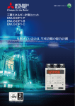
INVERTER FAMILY
Energy savings
(CO2 reduction)
Machine
tool
Amusement
facility
Air
conditioning
Pump
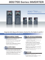
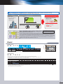
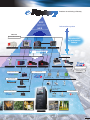
The best choice for a complete
range of applications.
Transfer
Lift
Winding and
unwinding
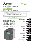
800/700 Series INVERTER
800/700 Series
Superior driving performance backed by the highest quality!
Main features of the 800/700 series
Environmentally friendly
• The EMC filter reduces electromagnetic noise
generated by the inverter. (Embedded in the
FR-A800 and F800 series inverters.)
• AC and DC reactors can be connected to suppress
the harmonic current to the power supply and to
improve the power factor.
• The inverters are compliant with the restriction of
hazardous substances (RoHS) directive of EU and
friendly to people and to the environment.
Drive performance
• The inverters provide powerful and consistent driving.
• The inverters can drive more highly efficient IPM
motors (magnet motors) as well as induction motors.
The inverters provide the solution to your further energy
saving needs. (FR-A800, F800, and F700PJ series)
The highly accurate PM sensorless vector control of
the FR-A800 series achieves productivity
improvement and energy saving at the same time.
Long-life and easy maintenance
• Long-life cooling fan*1 and long-life capacitor*1*2 are
incorporated (design life: 10 years)
*1: Surrounding air temperature: 40˚C on yearly average (free from corrosive
gas, flammable gas, oil mist, dust and dirt).
The design life is a calculated value and is not a guaranteed product life.
*2: Output current: 80% of the rated inverter current.
• Degradation degrees of the main circuit capacitor,
control circuit capacitor, and inrush current limit
resistor can be monitored. The inverter self diagnoses
the degradation degree and outputs a warning,
allowing trouble to be prevented.
• Upgrading to the succeeding models is easy with the
adoption of a removable control circuit terminal block.
(FR-A800, F800, and E700 series)
• Cooling fan replacement is performed in simple steps.
Maintenance of the inverter is easy.
Easy-to-use
• An operation panel is mounted as standard on all models.
• The Mitsubishi's setting dial is used.
• Use FR Configurator or FR Configurator2 to facilitate
operations from start-up to maintenance.
Revolutionizing the world of inverters
Major applications
Functions
and Performance
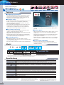
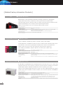
FR-A800
Advanced functionality and high-performance inverter
FR-F800
Enhanced next-generation energy-saving inverter
IP
55
&
IPM
Fans, pumps,
and
air conditioning
IM
&
IPM
Transfer, packaging, lifts,
machine tools, and presses
FR-E700
Simple, powerful, and compact inverter
FR-F700PJ
Air conditioning inverter
IM
Transfer, lifts, packaging,
machine tools, presses,
printing machines,
winding/unwinding,
ships, shield machines,
freezers, and cranes
Fans, pumps, and
air conditioning
IM
&
IPM
FR-D700
Simple and compact inverter
Transfer, packaging,
fibers, and
printing machines
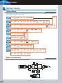
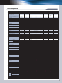
Capacity
Capacity table
Inverter Capacity *1
Model
0.1 0.2 0.4 0.75 1.5 2.2 3.7 5.5 7.5
11
15 18.5 22
30
37
45
55
75
90 110 132 160 185 220 250 280 315 355 400 450 500 560
FR-A820-K
FR-A840-K
FR-A842-K*2
FR-A846-K*3
FR-F820-K
FR-F840-K
FR-F842-K*2
FR-E720-K*4*5*6
FR-E740-K*4*5*6
Voltage class
FR-E720S-K*4
Three-phase 200 V
FR-E710W-K
FR-F720PJ-K(F)
Three-phase 400 V
*7
Single-phase 200 V (Note)
FR-F740PJ-K(F)*7
Single-phase 100 V (Note)
FR-D720-K
(Note) The output is three-phase 200 V.
FR-D740-K
FR-D720S-K
To be released soon
FR-D710W-K
*1: ND rated capacity for the FR-A800 series, and LD rated capacity for
the FR-F800 series.
*2: Separated converter type. Always install the converter unit (FR-CC2).
(Not required when a high power factor converter (FR-HC2) is used.)
*3: IP55 compatible model.
*4: SC at the end of the model name indicates
the safety stop function model.
*5: NF at the end of the model name indicates
the FL remote communication model.
*6: NC at the end of the model name indicates the CC-Link communication model.
*7: Filterpack (FR-BFP2) is enclosed for the inverter with Filterpack.
("F" is marked at the end of its model names on the packaging box.)
Mitsubishi's inverter family — meeting the needs of a full range of applications!
Vector inverter
FR-V500(L)
Inverter for pressure-resistant explosion-proof motor
1.5 kW to 75 kW (Three-phase 200 V)
1.5 kW to 250 kW (Three-phase 400 V)
FR-B
FR-B3
Inverter with power regeneration function
FR-A701
5.5 kW to 55 kW (Three-phase 200 V/400 V)
750 W to 75 kW (Three-phase 200 V)
750 W to 110 kW (Three-phase 400 V)
400 W to 37 kW (Three-phase 200 V/400 V)
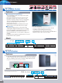
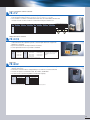
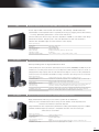
INVERTER FAMILY
(FR-A8AP mounted)
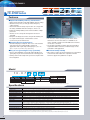
Advanced functionality and
high-performance inverter
FR-A800 Series
IM
&
IPM
High-function,
high-performance
High-function,
high-performance
Transfer
Lift
IP55
High-function,
high-performance
High-function,
high-performance
High-function,
high-performance
High-function,
high-performance
High-function,
high-performance
Press
Printing
Winding/unwinding
Food Packaging Machine tool
Features
Leading drive performance
• The enhanced Real sensorless vector control and vector control
achieves improved speed response and high-speed operation.
• The PM motor auto tuning function enables operation of other
manufacturers' permanent magnet (PM) motors.
Security & safety
• Controls with safety functions can be easily performed. (Safety stop function)
• 24 VDC control power input is equipped as standard. The
parameter setting and communication operation can be done
without turning ON the main power.
• The operating status immediately before the protective function is
activated can be stored with the trace function, facilitating the
trouble analysis at a separate location by using a USB memory
device and the inverter setup software (FR Configurator2).
FR-A800
which are suitable for power regeneration. Select the FR-CC2
converter unit according to the connected motor capacity (refer to
page 10).
Easy setup & easy to use
System support
• A USB host connecter (A type) is equipped. Parameters can be
copied to commercial USB memory devices.
• Highly reliable and easily wired spring clamp terminals have been
adopted for control circuit terminals.
• Parameter setting mode can be changed to the group parameter
mode, which provides intuitive and simple parameter settings. (The
• Rated current and four different overload capacity ratings (SLD rating,
LD rating, ND rating, and HD rating) can be selected with parameters.
(Multiple rating)
• Parameters and setting frequency can be changed at the program,
and the inverter control based on the machine specifications is
possible by the PLC function.
• A lineup of products compatible with the IP55 (400 V class) equipped
with the DC reactor is available. Inverters can be installed nearby
the machine.
conventional parameter setting mode is selected by default.)
Eco-friendly factories
• With Optimum excitation control, the excitation current is
constantly adjusted to drive the motor in the most efficient method
which leads to energy saving.
• The 315K or higher models are inverter-converter separated types,
Environmental adaptability
• A built-in noise filter (EMC filter), the newly developed drive
technology, and the power supply technology minimize the EMI
emitted from inverters.
Model
F R - A 8 2 0 - 0.4K -1
Symbol Voltage class
2
4
Symbol Structure, functionality
200 V class
400 V class
0
2
6
Standard model*3
Separated converter type*4
IP55 compatible model
Symbol**1 Description
0.4K to ND rated inverter
capacity (kW)
500K
00023 to SLD rated inverter
current (A)
12120
Symbol
Type
-1
-2
FM
CA*2
Circuit board coating
Symbol
(IEC60721-3-3 3C2/3S2 compatible)
Plated
conductor
None
-60
-06
Without
With
With
Without
Without
With
*1: IP55 compatible models have LD and ND rating types only. However, the SLD rated current of standard models is used to represent the model.
*2: For the CA-type, the monitor output terminal FM/CA operates as terminal CA (analog current output 0 to 20 mADC), not as terminal FM (pulse train output).
*3: For the 75K or higher inverter, always connect a DC reactor (FR-HEL), which is available as an option. Select a DC reactor according to the applied motor capacity.
*4: Always install the converter unit (FR-CC2). (Not required when a high power factor converter (FR-HC2) is used.)
Inverter model
Inverter capacity
FR-A820
FR-A840
FR-A842
FR-A846
0.4 kW to 90 kW
0.4 kW to 280 kW
315 kW to 500 kW
0.4 kW to 18.5 kW
* The FR-A846-22K to 132K are
to be released soon.
Specifications
Control method
Soft-PWM control, high carrier frequency PWM control (selectable among V/F control, Advanced magnetic flux vector control, Real
sensorless vector control), Optimum excitation control, vector control*1, and PM sensorless vector control
Starting torque
SLD rating: 120% 0.3 Hz, LD rating: 150% 0.3 Hz, ND rating: 200%*2 0.3 Hz, HD rating: 250%*2 0.3 Hz (with Real sensorless vector control or vector control*1)
Output frequency range
0.2 to 590 Hz (Up to 400 Hz with Advanced magnetic flux vector control, Real sensorless vector control, vector control*1 or PM sensorless vector control)
4
Regenerative
2.2K/3.7K··········· 100%3%ED
5.5K/7.5K·········· 100%2%ED
Maximum value/ 200 V class* : 0.4K to 1.5K······ 150%3%ED
braking torque*3 permissible duty
11K to 55K········ 20% continuous
75K or higher···· 10% continuous
5
(ND rating)
400 V class* : 0.4K to 7.5K······ 100%2%ED
11K to 55K·········· 20% continuous
75K or higher···· 10% continuous
Acceleration/deceleration time setting 0 to 3600 s (up to three types of accelerations and decelerations can be set individually.)
Multi-speed
15 speeds
Speed command
0 to 5 VDC, 0 to 10 VDC, 0 to ±5 VDC, 0 to ±10 VDC, 4 to 20 mA, digitally set with pulse train input, operation panel or parameter unit,
4-digit BCD or 16-bit binary (when using optional FR-A8AX)
Alarm output
1 changeover contact (230 VAC, 0.3 A, 30 VDC, 0.3 A), open collector output, alarm code (4-bit) output
Output signal
Five types of open collector outputs and two types of contact output (1 changeover contact) can be selected from inverter running, up to
frequency, frequency detection, operation ready, overload warning, error output and alarm, etc.
Monitor function
Restart after instantaneous power failure
One type can be selected from output frequency, motor current (steady or peak value), output voltage, operation speed, motor torque,
converter output voltage, regenerative brake duty, input power, output power and load meter, etc. Pulse train output (1440 pulses/s 2 mA)
and analog output (-10 to 10 VDC)
Available (reduced voltage method (frequency search selectable))
Removable terminal block
Used for control circuit terminals
Communication function
RS-485 supported (Mitsubishi inverter protocol, MODBUS®RTU) as standard, CC-Link, CC-Link IE Field Network, PROFIBUS-DP, and DeviceNet™ options available
*1: Available when an option (FR-A8AP) is mounted.
*2: In the initial setting for the FR-A820-00340(5.5K) or higher
and the FR-A840-00170(5.5K) or higher, the starting
torque is limited to 150% by the torque limit level.
2
*3: The regenerative braking torque indicates the average short-time torque (which
varies by the motor loss) that is generated when a motor decelerates in the
shortest time by itself from the rated speed. When a motor decelerates from a
speed higher than the rated speed, the average deceleration torque decreases.
When the regenerative power is large, use an option brake unit.
*4: The following performance can be attained when FR-ABR (option) is
connected: 150% torque and 10%ED for 0.4K and 0.75K, 100% torque
and 10%ED for 1.5K to 7.5K, 100% torque and 6%ED for 11K to 22K.
*5: The following performance can be attained when FR-ABR-H (option)
is connected: 100% torque and 10%ED for 0.4K and 0.75K, 100%
torque and 6%ED for 11K to 22K.
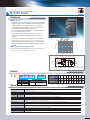
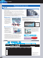
Enhanced next-generation
energy-saving inverter
FR-F800 Series
High-function,
high-performance
High-function,
high-performance
High-function,
high-performance
Fan
Pump
Air conditioning
IM
&
IPM
Features
Energy saving
• Advanced optimum excitation control, which has been newly
developed, provides a large starting torque while maintaining the
motor efficiency under the conventional Optimum excitation control.
• The tuning function enables operation of other manufacturers'
induction motors and PM motors, which increases the use in the
energy saving applications.
• With the 24 VDC external power supply, the input MC signal can be
turned OFF after the motor is stopped, and turned ON before
activating the motor. The inverter enables self power management
to reduce standby power.
FR-F800
Functions ideal for fans and pumps
• The rating can be selected between the two types (LD (light duty) or
SLD (superlight duty)) depending on the load of the fan/pump to be
used (multiple rating).
• The inverter can perform PID control of the motor operation and
control the external equipment at the same time (PID multiple loops).
The system cost can be reduced.
• By controlling the pumps connected in parallel (up to four pumps) by
the PID control, water volume, etc. can be adjusted by one inverter
(multi-pump function).
• Foreign matter on the impellers or fans of pumps can be removed
by repeating forward/reverse rotation and stopping of the motor
(cleaning function).
• The inverter is equipped with a temperature sensor, which outputs
a signal when the internal temperature is high.
• The operating status immediately before the protective function is
activated can be stored (trace function). A USB memory device and
the inverter setup software (FR Configurator2) facilitate the trouble
analysis at a separate location.
Compatibility with the environment
• A built-in noise filter (EMC filter) minimizes the EMI emitted from inverters.
• By installing a DC reactor (FR-HEL), which is available as an option,
they can conform to the Architectural Standard Specifications (2013
revision) supervised by the Ministry of Land, Infrastructure, Transport
and Tourism of Japan.
Security & safety
Easy setup & easy to use
• Controls with safety functions can be easily performed (safety stop function).
• With the 24 VDC external power supply, the parameter setting and
communication operation can be done without turning ON the
main circuit power.
• A USB host connecter (A type) is equipped. Parameters can be
copied to commercial USB memory devices.
• Highly reliable and easily wired spring clamp terminals have been
adopted for control circuit terminals.
Model
F R - F 8 2 0 - 0.75K -1
Symbol Voltage class
2
4
Symbol Structure, functionality
200 V class
400 V class
0
2
Standard model*2
Separated converter type*3
Symbol
Description
0.75K LD rated inverter
to 560K capacity (kW)
Symbol
Type
-1
-2
FM
CA*1
00023 SLD rated inverter
current (A)
to 12120
Symbol
(IEC60721-3-3 3C2/3S2 compatible)
Circuit board coating
Plated
conductor
None
-60
-06
Without
With
With
Without
Without
With
Inverter model
Inverter capacity
FR-F820
FR-F840
FR-F842
0.75 kW to 110 kW
0.75 kW to 315 kW
355 kW to 560 kW
*1: For the CA-type, the monitor output terminal FM/CA operates as terminal CA (analog current output 0 to 20 mADC), not as terminal FM (pulse train output).
*2: For the 75K or higher inverter, always connect a DC reactor (FR-HEL), which is available as an option. Select a DC reactor according to the applied motor capacity.
*3: Always install the converter unit (FR-CC2). (Not required when a high power factor converter (FR-HC2) is used)
Specifications
Soft-PWM control, high carrier frequency PWM control (selectable among V/F control (Optimum excitation control), Advanced
magnetic flux vector control (Advanced optimum excitation control), and PM motor control)
Control method
Starting torque
Induction motor
IPM motor
120% 0.5 Hz (Advanced magnetic flux vector control)
50%
Output frequency range
Regenerative braking
Induction motor
torque (Maximum value/
IPM motor
permissible duty)
Acceleration/deceleration time setting
0.2 to 590 Hz (Up to 400 Hz with Advanced magnetic flux vector control, and PM motor control.)
Multi-speed
15 speeds
Speed command
0 to 5 VDC, 0 to 10 VDC, 0 to ±5 VDC, 0 to ±10 VDC, 4 to 20 mA, pulse train input digitally set with operation panel or parameter
unit, 4-digit BCD or 16-bit binary (when using optional FR-A8AX)
0.75K to 55K····15% continuous, 75K or higher····10% continuous
Approximately 5% (1.5K or lower····Approximately 10%)*1
0 to 3600 s (up to three types of accelerations and decelerations can be set individually.)
Alarm output
1 changeover contact (230 VAC, 0.3 A, 30 VDC, 0.3 A), open collector output, alarm code (4-bit) output
Output signal
Five types of open collector outputs and two types of contact outputs (1 changeover contact) can be selected from inverter running, up to
frequency, frequency detection, operation ready, overload warning, error output and alarm, etc.
Monitor function
One monitored item can be selected from output frequency, motor current (steady or peak value), output voltage, operation speed,
converter output voltage, input power, output power and load meter, etc.
Pulse train output (1440 pulses/s 2 mA) and analog output (0 to 10 VDC)
Restart after instantaneous power failure
Available (reduced voltage method (frequency search selectable))
Removable terminal block
Used for control circuit terminals
Communication function
RS-485 supported (Mitsubishi inverter protocol, MODBUS®RTU) as standard, CC-Link, CC-Link IE Field Network, PROFIBUS-DP, DeviceNet™ options available
*1: Regenerative braking torque is the average short-time torque when a motor decelerates to a stop from the rated speed in the shortest time. (It varies with the motor loss.) It is not a continuous regenerative torque.
The average deceleration torque decreases when a motor decelerates from a speed higher than the rated speed.When the regenerative power is large, use a braking option.
3
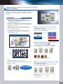
INVERTER FAMILY
Medium-function,
high-performance
Medium-function,
high-performance
Medium-function,
high-performance
Standard
Standard
Transfer
Lift
Packaging
Machine tool
Press
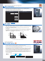
Simple, powerful, and compact inverter
FR-E700 Series
Features
Pursuing the best performance—top level of
driving performance in a compact body
• Advanced magnetic flux vector control enables accurate start-ups
for general-purpose industrial machines. (200% 0.5 Hz (3.7K or lower))
• Improved short-time permissible overload (200% for 3s) provides
powerful and consistent driving.
• Torque limit and current limit functions are available.
Easy-to-use (Outstanding operability and
diverse expandability)
• The non-slip, adaptable scroll speed setting dial allows for
quick jumps or precise increments based on turning speed.
• The operation mode can be selected in simple steps.
• This series has USB which enables easy setting from a
personal computer with FR Configurator.
• Plug-in options are available to add digital inputs/analog
outputs and to support different communication networks.
• For the customers who need more than the standard terminals,
the option terminal blocks, such as the 2-port RS-485 terminal
block, are available.
• The inverters with 0.4K or higher capacity have plug-in regenerative
brake transistors, which enable use for lift applications.
• An enclosure surface operation panel can be attached on an
enclosure surface and is available as an option.The operation
panel of the FR-E500 series can be also connected.
Compact and space-saving
• The mounting dimensions are the same as the conventional
FR-E500 model to keep backwards compatibility.
• Space can be saved with the side-by-side installation.
FR-E700
Improved reliability and easy maintenance
• Spring clamp terminals provide high reliability and easy wiring.
(FR-E700-SC/NF/NC)
• Shutoff circuit (hardware) securely provides emergency output
shutoffs. The inverter with the safety stop function can comply
with the safety standards without incurring too much cost.
(FR-E700-SC/NF/NC)
• The lives of the cooling fan and capacitor have been extended.
• Using the self-diagnosis function, the part life warning can be
output and the degree of deterioration can be monitored to
prevent malfunction.
• The removable control circuit terminal block simplifies
replacement work.
Environmentally friendly
• Filter options reduce the electromagnetic noise generated at
the inverter and enables compliance with the harmonic
suppression guidelines of Japan.
Model
F R - E 7 2 0
Symbol
2
Voltage class
200 V class
4
1
400 V class
100 V class
Symbol
None
Number of phases
Three-phase input
S
Single-phase input
W
Single-phase input
(double-voltage output)
- 3.7K
Symbol
Applicable motor capacity
0.1K to 15K
Represents the
capacity (kW)
Specifications
Symbol Control circuit terminal specification
None
SC
NF
NC
Standard control circuit terminal (screw type)
Safety stop function model
FL remote communication model
CC-Link communication model
Inverter model
FR-E720(SC)(NF)(NC)
FR-E740(SC)(NF)(NC)
FR-E720S(SC)*
FR-E710W*
Inverter capacity
0.1 kW to 15 kW
0.4 kW to 15 kW
0.1 kW to 2.2 kW
0.1 kW to 0.75 kW
* The output of the single-phase 200 V and single-phase 100 V input models is three-phase 200 V.
Control method
Soft-PWM control, high carrier frequency PWM control (V/F control, General-purpose magnetic flux vector control, Advanced magnetic
flux vector control or Optimum excitation control can be selected)
Starting torque
200%0.5 Hz (3.7K or lower) 150% 0.5 Hz (5.5K or higher) with Advanced magnetic flux vector control
Output frequency range
0.2 to 400 Hz
Regenerative braking torque*1 0.1K/0.2K·····150%, 0.4K/0.75K·····100%, 1.5K·····50%, 2.2K or higher·····20%
Acceleration/deceleration time setting 0 to 3600 s (up to two types of accelerations and decelerations can be set individually.)
Multi-speed
15 speeds
Speed command*2
0 to 5 VDC, 0 to 10 VDC, 4 to 20 mA, digital setting with setting dial, digital setting with operation panel or parameter unit
Safety stop*3
Output shutoff S1 and S2
Alarm output*4
1 changeover contact (230 VAC 0.3 A, 30 VDC 0.3 A), open collector output
Output signal*
Two types of open collector outputs and one type of contact output (1 changeover contact) can be selected from inverter running, up to
frequency, frequency detection, output current detection, operation ready, overload warning, fault output, and alarm, etc.
Monitor function
One monitored item can be selected from output frequency, motor current (steady or peak value), output voltage, frequency setting value,
motor torque, converter output voltage, regenerative brake duty, and output power, etc. Pulse train output (1440 pulse/s 1 mA)*5, analog
output 0 to 10 VDC (when using optional analog terminal block), pulse output (when using optional pulse train terminal block)
4
Restart after instantaneous power failure
Available (reduced voltage method (frequency search selectable))
Removable terminal block
Used for control circuit terminals
Communication function
RS-485 supported (Mitsubishi inverter protocol and MODBUS®RTU) as standard. CC-Link, PROFIBUS-DP, DeviceNet™, LONWORKS®
options available. FL remote communication and CC-Link communication models also available.
*1: Braking torque is the average short-time torque when a motor decelerates to a stop from 60 Hz in the shortest time. (It varies with the
motor loss.) It is not a continuous regenerative torque. The average deceleration torque becomes lower when a motor decelerates
from a frequency higher than the base frequency.The inverter is not equipped with a built-in brake resistor. Use an optional brake
resistor for an operation with large regenerative power. (Not available for 0.1K and 0.2K.) Brake unit (FR-BU2) can be also used.
*2: For the FL remote communication model, commands can be input from the operation panel or through FL remote communication.
For the CC-Link communication model, commands can be input from the operation panel or through CC-Link communication.
4
*3: Not available for the standard model.
*4: The FL remote communication model and the CC-Link communication model have
only one open collector output terminal. (For the FL remote communication model,
the terminal is fixed to output the safety monitor output signal (not selectable). )
*5: Not available for the FL remote communication model and the CC-Link
communication model.
Air conditioning inverter
FR-F700PJ Series
Standard
Standard
Standard
Fan
Pump
Air conditioning
IM
&
IPM
Features
Suitable for both the general-purpose motor
and the IPM motor
• This series can drive both a general-purpose motor and an
IPM motor. Switching between the two motor controls is
simple—just a single parameter setting. Initially, a general
purpose motor could be used, then upgraded to an IPM
motor without switching this inverter, leading to lower cost
of equipment.
Environmentally friendly
FR-F700PJ
• Power factor improving DC reactor, common mode choke
(line noise filter), capacitive filter (radio noise filter) are all essential
for air conditioning applications, and all of these are
included in the Filterpack. The inverter with Filterpack
(FR-F70PJ-F) is also available.
The wiring with different options is no longer required.
• Less wiring and smaller space is required when Filterpack
is used. Filterpack also enables compliance with the
harmonic suppression guideline, the architectural standard
specifications (electrical installation), and the architectural
standard specifications (machinery installation) (2013 revisions) in
Japan.
The inverter with Filterpack
Easy-to-use
• The following functions provide the ideal operation for fans
and pumps (PID control, Optimum excitation control, regeneration
avoidance, and automatic restart after instantaneous power failure).
Improved reliability and easy maintenance
• Spring clamp terminals provide high reliability and easy
wiring.
• The lives of the cooling fan and capacitor have been
extended.
• Using the self-diagnosis function, the component life
warning can be output and the degree of deterioration can
be monitored to prevent malfunction.
Model
F R - F 7 4 0 P J - 3.7K
Symbol
2
4
Voltage class
200 V class
400 V class
Symbol
Inverter capacity
0.4K to 15K
Represents the
capacity (kW)
<Precautions>
•Never drive an IPM motor in the IM drive setting.
•Use the same IPM motor capacity as the inverter capacity.
•For IPM motor, use an MM-EFS or MM-EF series motor.
Please contact us regarding a combination with
other manufacturer's IPM motor.
Symbol
None
F
Filterpack
Without
With*
Inverter model
FR-F720PJ
FR-F740PJ
Inverter capacity
0.4 kW to 15 kW
0.4 kW to 15 kW
*The inverter with Filterpack consists of an inverter and a Filterpack.
The inverter carries the rating plate, "FR-F70PJ-K," and the
Filterpack carries the rating plate "FR-BFP2-K."
Specifications
Control method
Starting
torque
Soft-PWM control, high carrier frequency PWM control (V/F control, General-purpose magnetic flux vector control, Optimum
excitation control, and IPM motor control can be selected)
General-purpose motor control 120% (at 1 Hz) with General-purpose magnetic flux vector control and slip compensation
IPM motor control
Output frequency range
50%
0.2 to 400 Hz
Regenerative General-purpose motor control 15%*1
braking torque IPM motor control
5% (10% for 1.5 kW or lower)*1
Acceleration/deceleration time setting
0.1 to 3600 s (up to two types of accelerations and decelerations can be set individually.)
Multi-speed
15 speeds
Speed command
0 to 5 VDC, 0 to 10 VDC, 4 to 20 mA, digital input with setting dial,
digital setting with operation panel or parameter unit
Alarm output
1 changeover contact (230 VAC 0.3 A, 30 VDC 0.3 A), open collector output
Output signal
One type of open collector output and one type of contact output (1 changeover contact) can be selected from inverter running, up
to frequency, frequency detection, output current detection, operation ready, overload warning, fault output, and alarm, etc.
Monitor function
One monitored item can be selected from output frequency, motor current (steady or peak value), output voltage, frequency setting
value, converter output voltage, regenerative brake duty, and output power, etc. Pulse train output (1440 pulses/s 1 mA)
Restart after instantaneous power failure
Available (reduced voltage method (frequency search selectable))
Communication function
RS-485 supported (Mitsubishi inverter protocol and MODBUS®RTU) as standard
*1: Regenerative braking torque is the average short-time torque when a motor decelerates to a stop from the rated speed in the shortest time. (It varies with the motor loss.) It is not a continuous regenerative torque.
The average deceleration torque becomes lower when a motor decelerates from a speed higher than the rated speed.When the regenerative power is large, use a braking option.
5
INVERTER FAMILY
Standard/medium
function
Standard/medium
function
Standard/medium
function
Standard
Standard
Standard
Standard
Transfer
Lift
Packaging
Machine tool
Air conditioning
Fan
Pump
Simple and compact inverter
FR-D700 Series
Features
Improved reliability and easy maintenance
• Spring clamp terminals provide high reliability and easy wiring.
• Shutoff circuit (hardware) securely provides emergency
output shutoffs.
• The inverter with the safety stop function can comply with
the safety standards without incurring too much cost.
• Parameter writing/reading can be restricted with a 4-digit
password.
• The lives of the cooling fan and capacitor have been
extended.
• Using the self-diagnosis function, the part life warning can
be output and the degree of deterioration can be
monitored to prevent malfunction.
Pursuing the best performance
• The General-purpose magnetic flux vector control and the
auto tuning function enable reliable operation in
applications that require large starting torque. (150% 1 Hz,
200% 3 Hz (3.7K or lower with the slip compensation))
FR-D700
• An enclosure surface operation panel, which can be
attached on an enclosure surface, is available as an
option. Operation panel for the FR-E500 series inverters
can be also connected.
• The inverters with 0.4K or higher capacity have built-in
regenerative brake transistors, and their usage can be
extended to a lift application.
Easy-to-use (pursuing the easy operation)
Environmentally friendly
• The non-slip, adaptable scroll speed setting dial allows for
quick jumps or precise increments based on turning speed.
• Setting can be made easily from a personal computer with
FR Configurator.
• Filter options reduce the electromagnetic noise generated
at the inverter and enables the compliance with the
harmonic suppression guidelines of Japan.
Model
F R - D 7 4 0
Symbol
Voltage class
Symbol
Number of phases
1
100 V class
None
Three-phase input
2
200 V class
S
Single-phase input
4
400 V class
W
Single-phase input
(double-voltage output)
- 0.4K
Symbol
Applicable motor capacity
0.1K to 15K
Represents the
capacity (kW)
Inverter model
FR-D720
FR-D740
Inverter capacity
0.1 kW to 15 kW
0.4 kW to 15 kW
FR-D720S*
0.1 kW to 2.2 kW
FR-D710W*
0.1 kW to 0.75 kW
*The output of the single-phase 200 V and
single-phase 100 V input models is three-phase 200 V.
Specifications
Control method
Soft-PWM control, high carrier frequency PWM control (V/F control, General-purpose magnetic flux vector control, Optimum excitation control can be selected)
Starting torque
150% 1 Hz, 200% 3 Hz (3.7K or lower) with General-purpose magnetic flux vector control and slip compensation
Output frequency range
0.2 to 400 Hz
Regenerative braking torque*1
0.1K/0.2K·····150%, 0.4K/0.75K·····100%, 1.5K·····50%, 2.2K or higher·····20%
Acceleration/deceleration time setting 0 to 3600 s (up to two types of accelerations and decelerations can be set individually.)
Multi-speed
15 speeds
Speed command
0 to 5 VDC, 0 to 10 VDC, 4 to 20 mA, digital input with setting dial, digital setting with operation panel or parameter unit
safety stop
Monitor output S0, output shutoff S1 and S2
Alarm output
1 changeover contact (230 VAC 0.3 A. 30 VDC 0.3 A), open collector output
Output signal
One type of open collector output and one type of contact output (1 changeover contact) can be selected from inverter running, up to
frequency, frequency detection, output current detection, operation ready, overload warning, fault output, and alarm, etc.
Monitor function
One monitored item can be selected from output frequency, motor current (steady or peak value), output voltage, frequency setting value,
converter output voltage, regenerative brake duty, and output power, etc. Pulse train output (1440 pulses/s 1 mA)
Restart after instantaneous power failure
Available (reduced voltage method (frequency search method selectable))
Communication function
RS-485 (Mitsubishi inverter protocol and MODBUS®RTU) supported as standard
*1: Braking torque is the average short-time torque when a motor decelerates to a stop from 60 Hz in the shortest time. (It varies with the motor loss.) It is not a continuous regenerative torque.
The average deceleration torque becomes lower when a motor decelerates from a frequency higher than the base frequency.
The inverter is not equipped with a built-in brake resistor. Use an option brake resistor for an operation with large regenerative power. Brake unit (FR-BU2) can be also used.
6
High-function,
high-performance
Inverter with power regeneration function
FR-A701 Series
Lift
Features
Easy-to-use
FR-A701
11K
15K
18.5K
22K
7.5K
5.5K
30K
37K
45K
55K
500
Usage time td (s)
• The number of wires in the main circuit has been reduced
to approx.40% and the installation area has been reduced
to approx.60% (for 7.5K) compared to the conventional
configuration with stand-alone common converters. Use
this model to save the wiring and the space.
• For easy replacement, the installation size is the same as
the conventional model (FR-A201).
• The braking circuit is built-in for this inverter, so the
selection procedure for a braking option is no longer
required.
• The total cost is reduced compared to the conventional
system (inverter + power regenerative converter + AC reactor). Less
heat is generated in this inverter because the regenerative
power is returned to the power supply, leading to energy
savings.
Pursuing the best performance
• It has excellent braking capacity. (The regenerative braking torque
300
200
100
50
30
is 100% for continuous operation and 150% for 60 s.)
10
10 20 30 40 50 60 70 80
Short-time permissible regenerative power WRS (kW)
Power regeneration
Power flow at regeneration
FR-A701
Power
supply
IM
AC reactor
(FR-HAL equivalent)
This section returns the regenerative power to the power supply.
• In power regeneration, large braking capacity is obtained by returning the regenerative energy to the power supply.
Model
F R - A 7 2 1 - 5.5K
Symbol Voltage class
A721 200 V class
A741 400 V class
Symbol
Applicable motor capacity
5.5K to 55K
Represents the
capacity (kW).
Applicable motor
5.5
(kW)
Three-phase 200 V class
FR-A721-
7.5
11
15 18.5 22
30
37
45
55
Three-phase 400 V class
FR-A741-
: Available
Specifications
Starting torque
Soft-PWM control, high carrier frequency PWM control (V/F control, Advanced magnetic flux vector control or Real sensorless vector control can
be selected) Vector control *1
150% 0.3 Hz with Real sensorless vector control or vector control*1
Output frequency range
0.2 to 400 Hz (Up to 120 Hz with Real sensorless vector control or vector control*1)
Regenerative Maximum value/
braking torque permissible duty
100% continuous 150% 60 s
Control method
Acceleration/deceleration time setting 0 to 3600 s (up to three types of accelerations and decelerations can be set individually.)
Multi-speed
15 speeds
Speed command
0 to 5 VDC, 0 to 10 VDC, 0 to ±5 VDC, 0 to ±10 VDC, 4 to 20 mA, digitally set with pulse train input, operation panel or parameter unit,
4-digit BCD or 16-bit binary (when using optional FR-A7AX)
Alarm output
1 changeover contact (230 VAC, 0.3 A, 30 VDC, 0.3 A), open collector output, alarm code (4-bit) output
Output signal
Five types of open collector outputs and two types of contact output (1 changeover contact) can be selected from inverter running, up to
frequency, instantaneous power failure (undervoltage), frequency detection, operation ready, overload warning, error output and alarm, etc.
Restart after instantaneous power failure
One type can be selected from output frequency, motor current, output voltage, operation speed, motor torque, converter output voltage
(steady or peak value), input power, output power and load meter, etc. Pulse train output (1440 pulses/s 2 mA) and analog output (0 to 10 VDC)
Available (reduced voltage method (frequency search selectable))
Removable terminal block
Used for control circuit terminals
Communication function
RS-485 supported (Mitsubishi inverter protocol and MODBUS®RTU) as standard, CC-Link, PROFIBUS-DP, DeviceNet™, LONWORKS®, and SSCNET III, options available
Monitor function
*1: Available when an option (FR-A7AP/FR-A7AL) is mounted.
7
INVERTER FAMILY
Premium high-efficiency IPM motor
Energy-saving
Energy-saving
Energy-saving
Fan
Pump
Air conditioning
Compatible inverter
MM-EFS/MM-THE4 Series
FR-F800
FR-F700PJ
Features
Energy savings with speed control
• The consumed power of a variable-torque load, such as fans, pumps,
and blowers, is proportional to the cube of its rotation speed.
Using this characteristic, the consumed power is reduced
when air volume is adjusted with speed control.
[Example of blower operation characteristic]
Damper control
MM-EFS Series
80
SF-JR/SF-TH motor
driven with inverter
60
40
SF-PR/SF-THE3 motor
driven with inverter
*1
IE4-equivalent efficiency level
• A premium high-efficiency IPM motor "MM-EFS series/MM-THE4
series" provides even better efficiency that is equivalent to IE4 (super
premium efficiency), the highest efficiency class*.
MM-EFS/MM-THE4
IPM motor driven with inverter
20
0
40
*1: Rate motor output is 100%.
60
Air volume (%)
80
100
[Comparison of
Mitsubishi products]
*As of March 2013
IEC 60034-30
Efficiency class
High
Energy savings with IPM motor
High efficiency achieved with IPM motors
• The IPM motors that have permanent magnets embedded in
their rotors are even more efficient than the high-performance
energy-saving motors.
Total efficiency (%)
Low
MM-EFS/MM-THE4
95
Efficiency of Mitsubishi motors
General-purpose motor
IPM motor
Premium high-efficiency
IPM (MM-EFS/MM-THE4)
IE4
(super premium efficiency)*3
IE3 (premium efficiency)
Super line premium series
(SF-PR, SF-THE3)
IE2 (high efficiency)
High-performance energysaving motor (SF-HR)
IE1 (standard efficiency)
[Comparison of efficiency]
100
Standard three-phase
motor (SF-JR)
Below the class
*3: The details of IE4 can be found in IEC 60034-31.
90
Smooth replacement from a general-purpose
motor (with the same installation size)
85
SF-PR/SF-THE3
80
75
• The frame number is the same (same size) as the Mitsubishi
general-purpose motors (4-pole SF-JR/SF-HR series). Replacement is
easy as the installation sizes are compatible. (55kW or lower)
SF-JR/SF-TH
70
Motor capacity (kW)
75
90
11
0
13
2
16
0
55
45
37
15
18
.5
22
30
0.
75
1.
5
2.
2
3.
7
5.
5
7.
5
11
65
[Compared to our
conventional product]
Why is the IPM motor more efficient?
• No current flows to the rotor (secondary side), and no
secondary copper loss is generated.
• Magnetic flux is generated with permanent magnets, and less
motor current is required.
• Embedded magnets provide reluctance torque*2, and the
reluctance torque can be applied.
General-purpose motor
[Comparison of losses at motors]
* Example of 22kW motors
Iron loss
Primary copper
100% loss (stator side)
Secondary copper
loss (rotor side)
Other
SF-JR
Premium high-efficiency
IPM motor
Iron loss
Primary copper 40%
loss
Other
MM-EFS
Motor structure (section view)
IPM motor (synchronous motor)
Stator coil
(three-phase coil)
S
N
Permanent
magnets
Stator core
N
S
N
N
S
S
N
S
S
Shaft
General-purpose motor (induction motor)
Stator coil
(three-phase coil)
Stator core
Shaft
N
Rotor conductor
Rotor core
*Example of 6-pole motor (copper or aluminum)
*2: Reluctance torque
Reluctance torque occurs due to magnetic imbalance on the rotor
8
Efficiency
Consumed power (%)
120
100
Rotor core
Same size
SF-JR 3.7kW
MM-EFS371M4
Improved lifespan and reliability
• Bearing grease lasts longer than that of general-purpose motors.
Design life: Approx. 7 years (60000 hours)
• The motor is equipped with anti-creep bearings as standard.
Slip does not occur with synchronous motor, and precise
operation is achievable.
• Magnetic pole positions are detected automatically.
The motor does not use a magnetic position sensor consisting
of electric devices, and that ensures high reliability.
Air conditioning in a building [Inverter + general-purpose motor (SF-JR)] [Inverter + IPM motor (MM-EFS)]
(Conditions: The electricity cost is 14 yen/kWh. The CO2 emission is 1,000 kWh ≈ 0.55 ton - CO2 emission)
Conditions
Operation patterns
[Units to drive]
The effects of replacing conventional
systems with inverter driven IPM motors
Air volume (%)
100
•Fans for air conditioning
5.5 kW x 10 units
7.5 kW x 10 units
3.7 kW x 100 units
•Annual energy saving effect
80
(differences in the
amount and cost)
50
Approx. 0.28 million kWh
Time
0
6
9
12
15
18
21
Approx.
24
•With general-purpose motor
•With IPM motor
Approx. 2.39 million kWh
Approx. 33.42 million yen
3.99 million yen
•Annual CO2 emission reduction
5110 hours/year
Approx. 0.28 million kWh
Approx. 2.1 million kWh
Approx. 29.43 million yen
157 tons
Easy calculation of the energy saving effect
(IPM energy savings simulation file)
Download the latest version from the
Mitsubishi Electric FA Global Website.
This Excel® simulation file enables calculation of the energy saving effect and CO2 reduction rate achieved by replacing
commercial power supply (damper/valve control) operation with IPM motor operation, general-purpose motor operation by
inverter, or high-efficiency motor operation by inverter. This file requires inputs such as the motor capacity, quantity, air volume,
the operating time, the annual operating time, the electricity cost, and the CO2 conversion coefficient. When you input the initial
cost and the bearing replacement cost, you can calculate how many years and months it will take to recover the initial cost.
Example of the energy savings calculation sheet Ver. 1.31
Model
[ 55 kW or lower ]
140
M M - E F S 7 1 M 4
Output
Symbol Rated speed*
1M
1500 r/min
Symbol Voltage class Symbol Specifications*
2
None
4
200 V
400 V
None Standard model
Q
Class B
Torque (%)
Symbol
See motor models See rated output
in table below
in table below
1
120
Symbol Specifications*
2
None Standard model
P1
Outdoor type
Short-time (60 s) maximum torque
100
80%
66.7%
80
Continuous
operation torque
60
40
20
0
150
0
300 500
*1: It can be also used for an application with the rated speed 1800 r/min.
*2: The outdoor type and class B are semi-standard models.
900 1200 1500 1800
2100
2250
Speed (r/min)
[ 75 kW or higher ]
M M - T H E 4
•The motor can be used for applications which required the rated speed of 1500 r/min and 1800 r/min.
•For dedicated motors such as the outdoor type, the long-axis type, the flange type, the waterproof outdoor type, and
the salt-damage proof specification type, contact your sales representative.
Rated output (kW)
Motor model name
200 V class
MM-EFS1M
400 V class
MM-EFS1M4
200 V class
MM-THE4
400 V class
0.75
7
1.5
15
2.2
22
3.7
37
5.5
55
7.5
75
Caution
· The IPM motor MM-EFS/MM-THE4 series cannot be driven by the commercial power supply.
· The total wiring length for an IPM motor should be 100 m or less.
· Only one IPM motor can be connected to each inverter.
11
11K
15
15K
18.5
18K
22
22K
30
30K
37
37K
45
45K
55
55K
75
—
90
—
110
—
: Available
132
—
160
—
: Not available
9
INVERTER FAMILY
High-function,
high-performance
High-function,
high-performance
High-function,
high-performance
High-function,
high-performance
High-function,
high-performance
High-function,
high-performance
High-function,
high-performance
Transfer
Lift
Packaging
Machine tool
Press
Printing
Winding/unwinding
Vector inverter
FR-V500(L) Series
Features
Pursuing the best performance
• The model adaptive speed control improves the speed
command trackability.
(Speed response 800rad/s (55K or lower), speed control range 1:1500)
• The adaptive magnetic flux observer reduces torque
fluctuation caused by changes in the motor temperature.
The motor's internal flux can be calculated at a high
accuracy, thus improving the torque accuracy.
(Repeated torque accuracy 5%.)
FR-V500
• The simple gain tuning function eliminates the need to
adjust the speed control gain and position loop gain.
Easy-to-use
• The machine analyzer function of the inverter setup
software (FR Configurator) vibrates the motor to analyze
the resonance frequency of the machine. The notch filter
function is available to avoid machine resonances.
• The terminal dedicated to encoder signals is equipped as
standard.
• Combination with a 1500 r/min dedicated motor (SF-V5RU) is
possible with the same capacities.
• Encoder expandability
The power voltage and output circuit can be selected
according to each encoder. (Differential line driver/
complementary, separate power supply (5.5/12/24 V) required.)
The dedicated motor (SF-V5RU) encoder is compatible with a
2048P/R resolution and 12 V power voltage.
Model
F R - V 5 2 0 - 1.5K Symbol
Voltage class
Symbol
Voltage class
V520 200 V class 55K or lower V520L 200 V class 75K or higher
V540
400 V class 55K or lower V540L 400 V class 75K or higher
Symbol
Applicable motor capacity
Symbol
Dedicated model
1.5K to 250K
Represents the
capacity (kW)
None
80
A1
Standard model
Sensorless vector control model
Dancer control model
Inverter model Inverter capacity
FR-V520(L)
1.5 kW to 75 kW
FR-V540(L)
1.5 kW to 250 kW
Converter unit
FR-CC2 Series
Features
• For the 800 series large-capacity inverters (FR-A800: 315K or higher, FR-F800: 355K
or higher), converter section (FR-CC2) and the inverter section are separated.
This can contribute to space and cost savings of large capacity systems
(except when one converter unit is connected to one inverter).
Converter section
(FR-CC2)
Separate
Inverter section
(FR-A842/F842)
M
Model
∙ Select the capacity of the converter unit according to the motor capacity.
∙ The converter unit has a built-in DC reactor.
F R - C C 2 - H 355K - 60
Three-phase 400 V class 315K
FR-CC2-H
(with the built-in DC reactor)
355K
400K
450K
500K
560K
630K
: Available
10
Symbol
H
Voltage class
400 V class
Capacity
Description
315K to 630K
Applicable motor
capacity (kW)
Circuit board coating Plated
Symbol (IEC60721-3-3 3C2/3S2 compatible) conductor
Without
-60
With
With
-06
With
*As the inverter does not have an explosion proof structure, install it in a non-hazardous place.
Hazardous area
Inverter for pressure-resistant explosion-proof type motor
FR-B, B3 Series
Chemical factory, etc.
• This inverter for pressure-resistant explosion-proof type motor, in combination with the
Mitsubishi pressure-resistant explosion-proof type motor, has passed the explosion-proof test
by the Japanese Ministry of Health, Labour and Welfare.
• Always install the inverter away from the explosive environment.
Variable torque type
Applicable motor output [kW]
0.2
0.4
0.75
1.5
2.2
3.7
5.5
7.5
11
15
22
30
37
45
55
75
90
110
Constant torque type
200 V class
400 V class
FR-B-750
FR-B-750
FR-B-1500
FR-B-2200
FR-B-3700
FR-B-5.5K
FR-B-7.5K
FR-B-11K
FR-B-15K
FR-B-22K
FR-B-30K
FR-B-37K
FR-B-45K
FR-B-55K
FR-B-75K
—
—
FR-B-1500
FR-B-2200
FR-B-3700
Vector control motor
FR-B-7.5K
FR-B-15K
FR-B-22K
FR-B-37K
Applicable motor output [kW]
0.4
0.75
1.5
2.2
3.7
5.5
7.5
11
15
18.5
22
30
37
200 V class
FR-B3-400
FR-B3-750
FR-B3-1500
FR-B3-2200
FR-B3-3700
FR-B3-5.5K
FR-B3-7.5K
FR-B3-11K
FR-B3-15K
FR-B3-18.5K
FR-B3-22K
FR-B3-30K
FR-B3-37K
400 V class
FR-B3-H400
FR-B3-H750
FR-B3-H1500
FR-B3-H2200
FR-B3-H3700
FR-B3-H5.5K
FR-B3-H7.5K
FR-B3-H11K
FR-B3-H15K
FR-B3-H18.5K
FR-B3-H22K
FR-B3-H30K
FR-B3-H37K
FR-B-55K
FR-B-75K
FR-B-90K
FR-B-110K
Dedicated motor
SF-V5RU
• When used in combination with the vector inverter FR-V500 or the FR-A800/FR-A701 inverter,
100% torque continuous operation is possible from 1500 r/min to the ultra-low speed of 0 r/min.
• An encoder and cooling fan are built-in.
• In addition to the standard type with legs, the flange type and type with brakes can be
manufactured.
• It is suitable for winder and unwinder applications. Motors with speed ratio of 1000/2000 r/min,
1000/3000 r/min and 500/2000 r/min specifications are available and they can support
applications whose winding diameter greatly changes.
(For 30 to 55 kW)
Short-term
maximum torque
150
Torque (%)
Torque (%)
(For 1.5 to 22 kW)
Continuous
operation
100
75
50
0
1500
150
100
94
Short-term
maximum torque
Continuous
operation torque
63
60
40
0
3000
Speed (r/min)
1500
Constant
output
Reduced
output
2400
3000
Speed (r/min)
*The maximum speed for the 55 kW is 2400 r/min.
Inverter for fans and pumps
FR-F700P Series
High-function,
high-performance
High-function,
high-performance
High-function,
high-performance
Fan
Pump
Air conditioning
IM
&
IPM
• Optimum excitation control continuously adjusts the excitation current to an optimum level to
provide the highest motor efficiency leading to substantial energy savings.
• This series can drive both a general-purpose motor and an IPM motor. Switching between the
two motor controls is simple—just a single parameter setting.
• The following functions provide the ideal operation for fans and pumps: variable torque acceleration
/deceleration patterns, PID control, commercial power supply switching, adjustable 5 points V/F,
continuous operation at an instantaneous power failure, regeneration avoidance function, etc.
• The newly developed built-in EMC filter reduces electromagnetic noise generated from the inverter.
• The lives of the cooling fan and capacitor have been extended. Using the self-diagnosis
function, the part life warning can be output and the degree of deterioration can be monitored
to prevent malfunction.
Model
F R - F 7 2 0 P - 3.7K
Symbol Voltage class
2
4
200 V class
400 V class
Symbol
Applicable motor capacity
0.75K to 560K Represents the capacity (kW)
Inverter model
Inverter capacity
FR-F720P
FR-F740P
0.75 kW to 110 kW
0.75 kW to 560 kW
11
INVERTER FAMILY
Option Series
Option lineup
A wide variety of options which improve function and performance, such as installation attachments,
are available for the FR series lineup.
Control
function
expansion
Additional
input/
output
1
Orientation
Encoder
control
Plug-in
feedback
option Machine end control
Vector
control
orientation
1
Plug-in
option
Position
control
Extra
High-resolution Digital
contact
analog input
output
input
16-bit/12-bit Pulse train
input
digital input
Communication
support
2
Plug-in
option
Improved
operability
4
Parameter
Operation
unit
Operation Parameter
Connectors
connection
unit
panel
option
Power
factor
improvement
Improved
regeneration
performance
Noise
reduction
Operation panel
mounting
attachment
System
support
RS-485
CC-Link
Encoder
Motor
pulse division thermistor
output
interface
6
AC
reactor
DC
reactor
Filterpack
7
Braking
option
Brake
resistor
Brake
unit
Power
regeneration
converter
10
Heatsink
attachment
11
Manual
FR series controller with DC tach.
follower
controller frequency
meter
and setter
12
Parts
and
others
Pilot
generator
Deviation
sensor
24VDC
input
SSCNET SSCNET III FL remote
3
Cable
option
5
FR
FR
Software Configurator2 Configurator
USB
cable
Power
regeneration
common
converter
EMC Directive
compliant Filterpack
noise filter
Totally enclosed
structure
Structure protrusion
specification
option
attachment
Built-in
encoder
power
supply
Trace
card
High power
factor
converter
Reactor
Radio noise Line noise
filter
filter
Additional
Analog output
open
Coded analog
collector
output
output
Relay
output
CC-Link IE
Field
CC-Link
LONWORKS® DeviceNet™ PROFIBUS-DP Modbus Plus Ethernet
Network
Netaork
cable
8
Noise
filter
Encoder
cable
9
Output
filter
Surge voltage
Sine wave
suppression
filter
filter
Attachment
EMC filter
DIN rail
Intercompatibility
for conduit
mounting mounting
attachment
attachment attachment
connection
Three
speed
selector
Remote
speed
setter
Frequency setting
potentiometer Frequency
Meter
meter
Potentiometer
Ratio
setter
Speed
detector
Master
controller
Soft
starter
Deviation
detector
Preamplifier
Calibration
resistor
Option connections
The main option connections are shown below.
DC reactor
(
AC reactor
EMC filter
Brake resistor
Thermal
relay
P1 P/+
R/L1
S/L2
T/L3
)
PR
Inverter
Output filter
Built-in
option
Motor
P/+ N/–
Line noise
filter
Radio noise
filter
Resistor unit
Brake unit
Power regeneration converter
12
Line noise
filter
SSCNET SSCNET III
cable
cable
List of options
: Available : Not available
FR-A800
FR-F800
FR-E700
Applicable inverter
FR-F700PJ
FR-A8AP
FR-A7AP
Orientation control/encoder feedback control
vector control/position control/encoder pulse dividing output
FR-A7AL
Orientation control
Pulse train input
FR-A5AP
Machine end orientation
FR-V5AM
Position control
FR-V5AP
12 V control circuit terminal block with encoder power supply
FR-A7PS
FR-A8AX
Name
Model
FR-V500(L)
FR-A701
Vector control/orientation
control are available as
standard
FR-A7AX
E-kit compatible
FR-V5AH
FR-A5AX
FR-A8AY
FR-A7AY
E-kit compatible
FR-A5AY
FR-A8AR
FR-A7AR
E-kit compatible
FR-A5AR
FR-A5NR
FR-D700
Plug-in option (control function expansion, additional input/output)
Orientation control
Encoder feedback control
Vector control
16-bit digital input
12-bit digital input
1
Analog output (2 terminals)
Digital output (7 terminals)
Relay output (3 terminals)
Relay output (1 terminal) (RS-485 communication)
Coded analog output
High-resolution analog input
FR-A7AZ
FR-E7DS
Compatible only with E700-SC
FR-V5AX
FR-V5AY
T-TRC50
PU connector (main body)
Standard
Standard
Standard
Standard
Standard
Standard
Dedicated terminal block (main body)
Standard
Standard
Standard
FR-A5NR
FR-E7TR
A connector
Standard
Standard
B connector
Standard
Mini B connector
Standard
Standard
Standard
FR-A8NC
FR-A7NC
E-kit compatible
FR-A5NC
Dedicated model
E700-NC
FR-A8NCE
FR-A7NL
E-kit compatible
FR-A8ND
FR-A7ND
E-kit compatible
FR-A5ND
FR-A8NP
FR-A7NP
E-kit compatible
FR-A5NPA
FR-A5NM
Compatible only with V500L
Motor thermistor interface
24 VDC input
Extra contact input (6 terminals)
High-resolution analog input
Motor thermistor interface
Additional open collector output
Encoder pulse division output
Trace card
Plug-in option (communication support)
RS-485
USB host
USB
USB device
CC-Link
2
CC-Link IE Field Network
LONWORKS®
DeviceNet™
PROFIBUS-DP
Modbus Plus
Standard *1
Only the standard
models are compatible
FR-V5NE
Compatible only with V500
Dedicated model
E700-NF
SSCNET
FR-V5NS
SSCNET III
FR-A7NS
FR-V7CBL
FR-V5CBL
FR-JCBL
USB cable
MR-J3USBCBL3M
SSCNET cable
FR-V5NSCBL
SSCNET III cable
MR-J3BUSM-
Ethernet
FL remote
Dedicated cable option
Encoder cable
3
Operation option
Parameter unit
4
LCD operation panel
Enclosure surface operation panel
Parameter unit connection cable
Operation panel connection connector
FR-PU07
*1
FR-PU07BB
*1
FR-PU04
*1
FR-PU04V
FR-LU08
FR-PA07
FR-CB20
FR-ADP
Software
5
FR Configurator2
SW1DND-FRC2-
FR-SW3-SETUP-W
*11
FR-SW1-SETUP-W
AC reactor
FR-HAL
DC reactor
FR-HEL
*2
MRS, MYS
FR Configurator
Reactor
6
Braking option
Brake resistor
*3
*3
*3
*3
*3
*3
*3
*4
*4
FR-ABR
*3
Brake unit
FR-BU2
*4
GRZG
FR-BR
MT-BR5
Resistor
7
High-duty brake resistor
Resistor unit
Power regeneration common converter
Dedicated standalone reactor
Power regeneration converter
High power factor converter
*4
*4
*4
FR-CV
FR-CVL
FR-RC
MT-RC
FR-HC2
13
INVERTER FAMILY
Name
Model
FR-A800
FR-F800
FR-E700
Applicable inverter
FR-F700PJ
FR-D700
FR-V500(L)
FR-A701
Noise filter
Radio noise filter
FR-BIF
Line noise filter
FR-BSF01
*5
*5
FR-BLF
*5
*5
Built-in filter
8
EMC Directive compliant noise filter
Filterpack (DC reactor and noise filter)
Equivalent part built-in Equivalent part built-in
Standard (2nd Environment)
SF
FR-E5NF
FR-S5NFSA
FR-BFP2
*6
FR-ASF
*7
*7
*9
*7
FR-BMF
*7
*7
*9
*7
MT-BSL(-HC)
*8
*8
*8
*8
Output filter
Surge voltage suppression filter
9
Sine wave filter
Reactor
Capacitor
MT-BSC
FR-A8CN
Structure option
FR-A5CN
MT-A5CN
FR-E7CN
Totally enclosed structure specification
FR-A5CV
attachment
FR-E7CV
Attachment for conduit connection
FR-A5FN
FR-A8TAT
FR-AAT
FR-A5AT
FR-E7AT
FR-F8AT
EMC filter mounting attachment
FR-E5T
DIN rail mounting attachment
FR-UDA
Manual controller with frequency meter
FR-AX
DC tach. follower
FR-AL
Three speed selector
FR-AT
Remote speed setter
FR-FK
Ratio setter
FR-FH
Speed detector
FR-FP
Master controller
FR-FG
Soft starter
FR-FC
Deviation detector
FR-FD
Preamplifier
FR-FA
Heatsink protrusion attachment
10
Control circuit terminal block
intercompatibility attachment
Intercompatibility attachment
*12
*10
*10
*10
FR Series controller and setter
11
Parts and others
Pilot generator
Deviation sensor
12
Frequency setting potentiometer, Meter, Potentiometer
Frequency meter
Calibration resistor
QVAH-10
YVGC-500W-NS
WA2W 1kΩ
YM206NRI 1 mA
RV24YN 10kΩ
*1: PU connector is disabled for the FL remote communication model and
the CC-Link communication model.
*2: The DC reactor is equipped as standard with the 75K or higher capacities.
*3: Only compatible with models which have a built-in brake transistor.
*4: The 200 V class 0.2K or lower, 400 V class 1.5K or lower cannot be used with the brake unit.
*5: An equivalent part (common mode choke) is built into the input side of 55K or lower capacities.
*6: Filterpack (FR-BFP2) is enclosed for the inverter with Filterpack
("F" is marked at the end of its model name on the packaging box).
14
*7: The filter can be used under V/F control or Advanced magnetic flux vector control.
*8: The filter can be used under V/F control.
*9: Not available under IPM motor control.
*10: Compatible with 3.7 kW or lower capacities.
*11: FR Configurator is not compatible with FL remote communication models.
*12: The FR-E7CV can be used only with the FR-E720-0.1K to 7.5K.
Power regeneration common converter
FR-CV
• Continuous regenerative operation at 100 % torque is possible with this converter. It is useful
for lift operation and line control. (Regeneration at a max. 150% torque for 60 s is possible.)
• This converter is a common converter. Each inverter does not need a brake unit when this
converter is used. Use this converter to cut down the total space and the cost.
Voltage
Applicable
inverter capacity
Main body
Applicable
inverter capacity
Main body
Dedicated
stand-alone reactor
Dedicated stand-alone reactor
7.5K
FR-CV-7.5K(-AT)
FR-CVL-7.5K
7.5K
FR-CV-H7.5K(-AT)
FR-CVL-H7.5K
11K
FR-CV-11K(-AT)
FR-CVL-11K
11K
FR-CV-H11K(-AT)
FR-CVL-H11K
Power regeneration common converter
15K
FR-CV-15K(-AT)
FR-CVL-15K
15K
FR-CV-H15K(-AT)
FR-CVL-H15K
22K
FR-CV-22K(-AT)
FR-CVL-22K
22K
FR-CV-H22K(-AT)
FR-CVL-H22K
30K
FR-CV-30K(-AT)
FR-CVL-30K
30K
FR-CV-H30K(-AT)
FR-CVL-H30K
37K
FR-CV-37K
FR-CVL-37K
37K
FR-CV-H37K
FR-CVL-H37K
55K
FR-CV-55K
FR-CVL-55K
55K
FR-CV-H55K
FR-CVL-H55K
200 V
Dedicated
stand-alone reactor Voltage
400 V
Inverter
1
Inverter
2
IM
1
IM
2
* Dedicated stand-alone reactor is an option.
High power factor converter
FR-HC2
• Harmonic current is greatly suppressed, and the equivalent capacity conversion
coefficient K5=0 in the "Japanese specific consumer higher harmonics suppression
guidelines" is achieved.
• Input current waveforms are improved to be sine waves.
• Power regeneration function is provided as standard.
Voltage class High power factor converter Voltage class
FR-HC2-7.5K
FR-HC2-15K
200 V
class
FR-HC2-30K
FR-HC2-55K
400 V
class
FR-HC2-75K
High power factor converter
FR-HC2-H7.5K
FR-HC2-H160K
FR-HC2-H15K
FR-HC2-H220K
FR-HC2-H30K
FR-HC2-H280K
FR-HC2-H55K
FR-HC2-H400K
FR-HC2-H75K
FR-HC2-H560K
Standard accessories
Reactor 1, reactor 2, external box*
(Use in combination with the above
accessories. The wires for connecting
the standard accessories are not
included.)
FR-HC2-H110K
* Peripheral devices are separately provided for FR-HC2-H280K or higher (not provided in a box).
Brake unit
FR-BU2
• The regenerative power from the motor is consumed as heat to improve the braking
capacity of the motor.
• Connect this unit to the DC bus voltage directly to use with the conventional inverter.
• This unit can replace conventional models, BU, FR-BU, and MT-BU5.
• The units can be connected in parallel to handle large capacity.
Voltage class
Brake unit model
Voltage class
FR-BU2-1.5K
FR-BU2-H7.5K
FR-BU2-3.7K
200 V
class*
FR-BU2-7.5K
FR-BU2-15K
Brake unit model
FR-BU2-H15K
400 V
class*
FR-BU2-H30K
FR-BU2-H55K
FR-BU2-30K
FR-BU2-H75K
FR-BU2-55K
FR-BU2-H220K
FR-BU2-H280K
* Resistors and resistor units are required. Refer to the Instruction Manual for the combination patterns.
15
INVERTER FAMILY
Mitsubishi Product Guide
High-performance energy-saving motor
SF-PR
We have released the superline premium series SF-PR models compatible with
IE3 premium efficiency ahead of the three-phase motor energy efficiency
regulations in Japan.
The SF-PR has achieved the efficiency class IE3 with the same dimensions as
those of conventional models using our unique technology of the steel plate
frame and new core materials.
It maintains interchangeability with our standard motor SF-JR and easy
replacement becomes possible. By adopting a high-efficiency motor, energy
savings in plant facilities and reduction of electricity consumption are expected,
as well as the effects of recovering the investment cost.
Introduction effects of the superline premium series SF-PR
One motor conforms to the power supply in Japan and
the United States.
• The SF-PR series conform to
the Top Runner Standard of
the "Act on the Rational Use
of Energy (energy saving law)" to
be applied on April 1, 2015.
• The 230 V 60 Hz motors of
the series also conform to the
Energy Independence and
Security Act (EISA).
The SF-PR motor conforms to the Top Runner Standard (IE3 equivalent), which
remarkably reduces its operation cost (electricity charges) and greatly contributes
minimization of TCO (Total Cost Ownership).
• Trial calculation example of an annual saved sum of money (at upgrading
the motor from energy-efficiency class IE1 to IE3)
200/200/220 V
50/ 60/ 60 Hz
Motor with 4-poles 200 V 50 Hz
230 V
60 Hz
Annual saved sum of money [yen]
80000
The annual saved sum
of money is calculated in
the following conditions.
60000
200
50
200
60
220
60
230
60
V
Hz
· Annual operation time
4,380h (12h/day, 365days)
· Electricity rate
16yen/kWh
· Load ratio
75%
40000
20000
In the United States
*For the 200 V class
Interchangeable installation size
• Replacement can be smoothly
performed because the
installation size (frame number) is
compatible with our standard
motor SF-JR series.
• It is possible to use a power
distribution control equipment
(thermal relay and breaker), which is
the same as a conventional one.
0
0.75 1.5
2.2
3.7 5.5 7.5
11
15 18.5 22
Output [kW]
30
37
45
55
(When adjusted to be the same load.)
• Economic efficiency on an energy saving effect
Replaceable in the
same space
Cost (Product + Electricity rate)
In Japan
SF-PR
Excellent interchangeability with
the same shaft diameter and the
same shaft height!
The point of the energy
saving effect
Cost
benefits
SF-JR
SF-PR
(Premium Efficiency)
Reduction in the electricity charges through the
energy saving enables the investment cost to be
recovered, and after that, the energy saving effect
will bring some profit through power saving.
The annual saved sum of money can be
calculated according to the following formula.
The longer operation time in an application, the
more money can be saved.
Number of years of use
Recovery period for the Breakeven point
amount of a price increase
<Calculation formula>
*1 For the frame number 180 LD or higher and some models of the 6P product, the total length or
diametrical dimension is greatly different.
*2 The frame number is different from 1.5 kW6P (112M), 2.2 kW6P(132S) of the SF-HR models.
*3 When replacing the SF-JR to the SF-PR, it is required to consider upgrading the contactor to secure the
same electric durability as using the SF-JR because the electric durability of the contactor may reduce
by about 30%. Besides, when replacing the SF-JR to the SF-PR, the existing thermal relay may trip
depending on the operating conditions (long starting time ). As a countermeasure, consider "Adjusting
the heater set value of the thermal" or "Adopting the thermal with a saturated reactor ", etc.
*4 If the breaker NF400-SW manufactured by Mitsubishi Electric is used with the 55 kW motor (Y-
starting), change the breaker. (Change the rated current of the breaker NF400-SW from 300 A to 350 A.)
Output
(kW)
Efficiency of
current motor
(%)
Efficiency of
SF-PR model
(%)
Number
of
motors
Number
of hours
of use
(h/day)
Number
of days of
operation
(day/year)
Electricity
rate
(yen/kWh)
When replacing our standard motor SF-JR with the SF-PR on the ventilation fan in plant
<Condition>
Type : 11 kW 4P 200 V 50 Hz 75% load
Units : 10units
Operation time : 12h/day 365day/year
Electricity rate: 16yen/kWh
Reduced cost of
about 350,000 yen
per year
Trial calculation results in replacing the SF-JR with the SF-PR with improved efficiency by 5%
under the same conditions of the load factor, operation time, and electricity charges, etc.
Lineup
S F - P R V O B - KR
Structure
Symbol
S
Superline series
Symbol Enclosure type
F
Totally enclosed
fan-cooled
Symbol
Series
Symbol Installation
Symbol
Classification
Symbol Classification
PR
Premium series
Steel plate frame
None Horizontal type
V Vertical type
Flange type
F
None
O
Indoor type (IP44)
Outdoor type (IP44)
Dust-proof and waterproof type (IP55)
None Without brake
B
With brake
•Available range
Type
Model
Number of poles
0.75
1.5
2.2
3.7
5.5
7.5
Output
11
[kW]
15
18.5
22
30
37
45
55
16
Foot mounting type
SF-PR
2P
4P
6P
Vertical type
SF-PRV
2P
4P
6P
—
—
Totally enclosed fan-cooled
Flange type
SF-PRF
2P
4P
6P
—
—
—
—
P
2P
Outdoor type
SF-PRO
4P
6P
—
Symbol
Country code
None Japan and the U.S.A.
Korea
KR
Europe
EU
Dust-proof and waterproof type
SF-PRP
2P
4P
6P
—
: Available range
· The vertical type and the flange type are
also available for the outdoor type and
the dustproof/waterproof type.
· SF-THE3 is used for the frame number
of 250 or higher.
Mitsubishi Molded Case Circuit Breakers and Earth Leakage Circuit Breakers
WS-V Series
"WS-V Series" is the new circuit breakers that have a lot of superior
aspects such as higher breaking capacity, design for easy use,
standardization of accessory parts, and compliance to the global
standards.
Features
Technologies based on long years of
experience are brought together to achieve
improved performance
The new circuit breaking technology "Expanded ISTAC" has
improved the currentlimiting performance and upgraded the
overall breaking capacity.
Expansion of the conductor under the stator shortens the
contact parting time of the mover as compared to the
conventional ISTAC structure.
The current-limiting performance has been improved
remarkably. (The maximum peak current value has been
reduced by approx. 10%.)
Types of internal accessories are reduced
from 3 types to 1 type
Standardization of internal accessories contributes to a
reduction of stock and delivery time.
For 32/63AF
Conventional models Three types
For 125AF
New circuit breaking technology (Expanded ISTAC)
For 250AF
New models
For 32 to 250AF
One type
Applicable accessories
AL
AX
AL+AX
SHT
UVT
Lineup of UL 489 listed circuit breakers with
54 mm width "Small Fit"
The compact breakers contribute to a size reduction of
machines, and IEC 35 mm rail mounting is standard.
Breaking capacity comparison with a conventional model
20 %
UP
Model Name
250-RG
50 %
UP
250-H
20 %
UP
250-S
NF50-SVFU
WS-V Series
WS Series
NF100-CVFU
NV50-SVFU
NV100-CVFU
38.8%
UP
250-C
20 %
UP
125-RG
20
40
60
80
100
120
140
160
kA at 400 V AC lcu
For security and standard compliance of machines, F-type and
V-typeoperating handles are available for breakers with 54 mm width.
Compact design for ease of use
The thermal adjustable circuit breakers and electronic circuit
breakers are smaller.
NF250-SGW
NF250-SGV
Volume ratio 79%
Lineup of UL 489 listed circuit breakers for 480 V
AC "High Performance"
The breaking capacity has been improved to satisfy the
request for SCCR upgrading.
(Compared with our conventional models)
(Conventional model:
105 x 165 x 86 mm)
(New model:
105 x 165 x 68 mm)
NF125-SVU
NF125-HVU
NF250-SVU
NF250-HVU
Breaking capacity of UL 489 listed circuit breakers for 480 V AC (UL 489)
NF125-SVU/NV125-SVU ................................ 30 kA
NF125-HVU/NV125-HVU ................................ 50 kA
NF250-SVU/NV250-SVU ................................ 35 kA
NF250-HVU/NV250-HVU ................................ 50 kA
17
INVERTER FAMILY
Mitsubishi Magnetic Motor Starters and Magnetic Contactors
MS-T Series
MS-T series is newly released!
The MS-T series is smaller than ever, enabling more compact control
panel. The MS-T series is suitable for other
Mitsubishi FA equipment. In addition, the MS-T conforms to a variety of
global standards, supporting the global use.
Features
Compact
Just 36 mm wide for 10 A-frame type!
General-purpose magnetic contactor with smallest width*1 in the
industry. The width of MS-T series is reduced by 32% as compared
to the prior MS-N series, enabling a more compact panel.
*1: Based on Mitsubishi Electric research as of October 2013 in the general-purpose magnetic
contactor industry for 10 A-frame class.
Frame size
[Unit: mm]
11 A
13 A
43
MS-N series
1/L1
3/L2
5/L3
4/T2
6/T3
13
1/L1
14
2/T1
S-N10
3/L2
4/T2
5/L3
6/T3
13
13
14
14
S-N11(Auxiliary 1-pole)
1/L1
2/T1
3/L2
4/T2
25 A
5/L3
63
6/T3
75
1/L1
3/L2
5/L3
2/T1
4/T2
6/T3
1/L1 3/L2 5/L3
21
22
13
21
14
22
13
21
S-N12 (Auxiliary 2-pole)
43
31
22
14
2/T1 4/T2 6/T3
32
44
S-N20
43
36
New
MS-T series
53
43
Front view
2/T1
20 A
S-N25
63
43
Front view
m!
!
!
m
-10m
-7mm
S-T10
!
m
-12m
-20m
S-T12 (Auxiliary 2-pole)
S-T20
S-T25
Standardization
• Covers provided as standard equipment
Terminal cover and auxiliary contact unit covers are provided as standard equipment. Not only ensuring your safety, but
also saving you time and cost of selecting and purchasing the covers separately.
• Wide-ranged operation coil rating
The prior series had 14 types of the operation coil rating. Owing to the wideranged operation coil rating, the number of
the rating types for the MS-T series is reduced to half, making it easier to select as compared to the prior model.
Consolidating the number of the produced coils type allows not just the reduction of customer storage, but also
shortening of delivery time.
Coil
designation
rs are
Cove ed as
h
c
a
tt
a
ard.
stand
Covers + Contactor
Global Standard
AC12 V
AC24 V
AC48 V
AC100 V
AC120 V
AC127 V
AC200 V
AC220 V
AC230 V
AC260 V
AC380 V
AC400 V
AC440 V
AC500 V
Rated voltage [V]
Coil
designation 50 Hz/60 Hz
Rated voltage [V]
50 Hz
60 Hz
12
24
48 to 50
100
110 to 120
125 to 127
200
208 to 220
220 to 240
240 to 260
346 to 380
380 to 415
415 to 440
500
12
24
48 to 50
100 to 110
115 to 120
127
200 to 220
220
230 to 240
260 to 280
380
400 to 440
460 to 480
500 to 550
AC24 V
AC48 V
AC100 V
AC200 V
AC300 V
AC400 V
AC500 V
24
48 to 50
100 to 127
200 to 240
260 to 300
380 to 440
460 to 550
(12 V type is an order-made product.)
• Conforms to various global standards
Not only major global standards such as IEC, JIS, UL, CE, and CCC but also ship standards and other country
standards are planned to be certified.
• Conforms to various global standards
International
Standard
*1
Japan
Applicable Standard
Europe
EN
Certification Body
EC Directive
Safety Standard
U.S.A. and Canada
China
GB
*2
*1: The MS-T series also provide safe isolation (mirror contact) specified in the IEC standard.
*2: The motor starters are certified under each type name of the magnetic contactors and the thermal overload relays on the condition that the magnetic contactors and
the thermal overload relays are used in combination.
18
Mitsubishi Magnetic Motor Starters and Magnetic Contactors
MS-N Series
Environment-friendly Mitsubishi MS-N series ensures safety and
conforms to various global standards. Its compact size contributes
to space-saving in a machine. The MS-N series is suitable for
other Mitsubishi FA equipment and can be used globally.
Features
Bifurcated contact adopted to achieve high contact reliability
Contact reliability is greatly improved by combining bifurcated moving
contact and stationary contact.
This series responds to the various needs such as the application to
safety circuit. (The MS-T series also has bifurcated contacts.)
Mirror contact (auxiliary contact off at main contact welding)
The MS-N series meets requirements of "Control functions in the
event of failure" described in EN 60204-1 "Electrical equipment of
machines", being suitable as interlock circuit contact. The MS-N
series is applicable for category 4 safety circuit. We ensure safety for
our customers. (The MS-T series also has mirror contacts.)
Main contact welding
Various option unit
Various options including surge absorbers and additional auxiliary
contact blocks are available.
Auxiliary normally
closed contact
Gap
• Conforms to various global standards
Model
S-N10 to S-N400
MSO-N10 to MSO-N400
TH-N12KP to TH-N400KP
IEC
International
Applicable Standard
JIS
DIN/VDE
BS/EN
Japan
Germany England/Europe
Safety Standard
UL
CSA
U.S.A
Canada
: Compliant as standard
EC Directive Certification Body
CCC
TÜV
GB
CE Marking
Europe
Germany
China
Mitsubishi energy measuring module
EcoMonitorLight
The handy, low cost energy measuring module with
an integrated display visualizes energy consumption.
Features
Measurement and display of the energy
consumption in a single module
With the built-in LCD display, the single module enables
measurement and display of the energy consumption.
The module can be used for simple measurement of the
production equipment (motors, compressors, etc.) and verification of the
energy saving effect by measuring the energy consumption before
and after introduction of high-efficiency equipment (inverters, etc.).
Production equipment
System coordination facilitated by the standard
MODBUS® RTU communication function
The MODBUS® RTU communication is supported as standard,
facilitating coordination with the host system (programmable controller,
GOT, etc.).
For example, by using GOT to visualize the energy consumption
at work sites, you can raise the awareness of energy saving, and
achieve the energy management in response to the actual
operation of the production equipment.
* The GOT sample screen data can be downloaded free of charge from the Mitsubishi Electric
FA Global Website.
GOT screen
MODBUS®
RTU communication
Energy measuring module in the enclosure
Energy information is transmitted to GOT
using MODBUS® RTU communication.
19
INVERTER FAMILY
Molded case circuit breaker, magnetic contactor, cable gauge (FR-A800)
•280K or lower
Voltage
200 V
class
400 V
class
Motor
output
(kW)**1
Applicable inverter model
(ND rating)
Molded case circuit breaker (MCCB)**2 or earth
leakage circuit breaker (ELB) (NF, NV type)
Power factor improving (AC or DC)
reactor connection
Input side magnetic contactor *3
Power factor improving (AC or DC)
reactor connection
Recommended
Cable gauge (mm2) *4
Without
With
Without
With
R/L1, S/L2,
T/L3
U, V, W
0.4
FR-A820-00046 (0.4K)
5A
5A
S-T10
S-T10
2
2
0.75
FR-A820-00077 (0.75K)
10 A
10 A
S-T10
S-T10
2
2
1.5
FR-A820-00105 (1.5K)
15 A
15 A
S-T10
S-T10
2
2
2.2
FR-A820-00167 (2.2K)
20 A
15 A
S-T10
S-T10
2
2
3.7
FR-A820-00250 (3.7K)
30 A
30 A
S-T21
S-T10
3.5
3.5
5.5
FR-A820-00340 (5.5K)
50 A
40 A
S-N25
S-T21
5.5
5.5
7.5
FR-A820-00490 (7.5K)
60 A
50 A
S-N25
S-N25
14
8
11
FR-A820-00630 (11K)
75 A
75 A
S-N35
S-N35
14
14
15
FR-A820-00770 (15K)
125 A
100 A
S-N50
S-N50
22
22
18.5
FR-A820-00930 (18.5K)
150 A
125 A
S-N65
S-N50
38
38
22
FR-A820-01250 (22K)
175 A
150 A
S-N80
S-N65
38
38
30
FR-A820-01540 (30K)
225 A
175 A
S-N95
S-N80
60
60
37
FR-A820-01870 (37K)
250 A
225 A
S-N150
S-N125
80
80
45
FR-A820-02330 (45K)
300 A
300 A
S-N180
S-N150
100
100
55
FR-A820-03160 (55K)
400 A
350 A
S-N220
S-N180
100
100
75
FR-A820-03800 (75K)
—
400 A
—
S-N300
125
125
90
FR-A820-04750 (90K)
—
400 A
—
S-N300
150
150
0.4
FR-A840-00023 (0.4K)
5A
5A
S-T10
S-T10
2
2
0.75
FR-A840-00038 (0.75K)
5A
5A
S-T10
S-T10
2
2
1.5
FR-A840-00052 (1.5K)
10 A
10 A
S-T10
S-T10
2
2
2.2
FR-A840-00083 (2.2K)
10 A
10 A
S-T10
S-T10
2
2
3.7
FR-A840-00126 (3.7K)
20 A
15 A
S-T10
S-T10
2
2
5.5
FR-A840-00170 (5.5K)
30 A
20 A
S-T21
S-T12
2
2
7.5
FR-A840-00250 (7.5K)
30 A
30 A
S-T21
S-T21
3.5
3.5
11
FR-A840-00310 (11K)
50 A
40 A
S-T21
S-T21
5.5
5.5
15
FR-A840-00380 (15K)
60 A
50 A
S-N25
S-T21
8
8
18.5
FR-A840-00470 (18.5K)
75 A
60 A
S-N25
S-N25
14
8
22
FR-A840-00620 (22K)
100 A
75 A
S-N35
S-N25
14
14
30
FR-A840-00770 (30K)
125 A
100 A
S-N50
S-N50
22
22
37
FR-A840-00930 (37K)
150 A
125 A
S-N65
S-N50
22
22
45
FR-A840-01160 (45K)
175 A
150 A
S-N80
S-N65
38
38
55
FR-A840-01800 (55K)
200 A
175 A
S-N80
S-N80
60
60
75
FR-A840-02160 (75K)
—
225 A
—
S-N95
60
60
90
FR-A840-02600 (90K)
—
225 A
—
S-N150
60
60
110
FR-A840-03250 (110K)
—
225 A
—
S-N180
80
80
132
FR-A840-03610 (132K)
—
400 A
—
S-N220
100
100
150
FR-A840-04320 (160K)
—
400 A
—
S-N300
125
150
160
FR-A840-04320 (160K)
—
400 A
—
S-N300
125
150
185
FR-A840-04810 (185K)
—
400 A
—
S-N300
150
150
220
FR-A840-05470 (220K)
—
500 A
—
S-N400
2×100
2×100
250
FR-A840-06100 (250K)
—
600 A
—
S-N600
2×100
2×100
280
FR-A840-06830 (280K)
—
600 A
—
S-N600
2×125
2×125
*1: Assumes the use of an IPM motor MM-CF or a Mitsubishi 4-pole standard motor with the motor capacity of 200 VAC 50 Hz.
*2: Select an MCCB according to the power supply capacity.
Install one MCCB per inverter.
For the use in the United States or Canada, provide the appropriate UL and cUL listed fuse or UL489 molded case circuit breaker (MCCB)
that is suitable for branch circuit protection. (Refer to the Instruction Manual (Detailed).)
*3: The magnetic contactor is selected based on the AC-1 class. The electrical durability of magnetic contactor is 500,000 times. When the
magnetic contactor is used for emergency stops during motor driving, the electrical durability is 25 times.
If using an MC for emergency stop during motor driving or using it on the motor side during commercial power supply operation, select an
MC with the class AC-3 rated current for the rated motor current.
*4: Cables
For FR-A820-03160(55K) or lower and FR-A840-01800(55K) or lower, it is the gauge of a cable with the continuous maximum permissible
temperature of 75°C. (HIV cable (600 V grade heat-resistant PVC insulated wire), etc.) It assumes a surrounding air temperature of 50°C or
lower and the wiring distance of 20 m or shorter.
For FR-A820-03800(75K) or higher and FR-A840-02160(75K) or higher, it is the gauge of the cable with the continuous maximum permissible
temperature of 90°C or higher. (LMFC (heat resistant flexible cross-linked polyethylene insulated cable), etc.) It assumes a surrounding air
temperature of 50°C or lower and in-enclosure wiring.
MCCB
INV
M
MCCB
INV
M
NOTE
• When the inverter capacity is larger than the motor capacity, select an MCCB and a magnetic contactor according to the inverter model, and select cables and reactors
according to the motor output.
• When the breaker on the inverter's input side trips, check for the wiring fault (short circuit), damage to internal parts of the inverter etc. The cause of the trip must be identified
and removed before turning ON the power of the breaker.
20
•315K or higher
Voltage
400 V
class
Motor
output
(kW)**1
Applicable inverter model
(ND rating)
Applicable
converter model
Molded case circuit
breaker (MCCB)**2
or earth leakage
circuit breaker (ELB)
(NF, NV type)
Input-side
magnetic
contactor *3
315
FR-A842-07700 (315K)
FR-CC2-H315K-60
700 A
355
FR-A842-08660 (355K)
FR-CC2-H355K-60
800 A
400
FR-A842-09620 (400K)
FR-CC2-H400K-60
450
FR-A842-10940 (450K)
500
FR-A842-12120 (500K)
HIV cables, etc. (mm2) *4
R/L1,
S/L2,
T/L3
P/+, N/-
U, V, W
S-N600
2 x 150
2 x 150
2 x 150
S-N600
2 x 200
2 x 200
2 x 200
900 A
S-N800
2 x 200
2 x 200
2 x 200
FR-CC2-H450K-60
1000 A
1000 A rated product
2 x 250
2 x 250
2 x 250
FR-CC2-H500K-60
1200 A
1000 A rated product
3 x 200
3 x 200
2 x 250
*1: Assumes the use of a Mitsubishi 4-pole standard motor with the motor capacity of 400 VAC 50 Hz.
*2: Select an MCCB according to the power supply capacity.
MCCB
Install one MCCB per converter.
For the use in the United States or Canada, provide the appropriate UL and cUL listed fuse that is suitable for branch circuit
MCCB
protection. (Refer to the Instruction Manual (Detailed) of the inverter.)
*3: The magnetic contactor is selected based on the AC-1 class. The electrical durability of magnetic contactor is 500,000 times. When the
magnetic contactor is used for emergency stops during motor driving, the electrical durability is 25 times.
If using an MC for emergency stop during driving the motor, select an MC regarding the converter unit input side current as
JEM1038-AC-3 class rated current. When using an MC on the inverter output side for commercial-power supply operation switching
using a general-purpose motor, select an MC regarding the rated motor current as JEM1038-AC-3 class rated current.
*4: The gauge of the cable with the continuous maximum permissible temperature of 90°C or higher. (LMFC (heat resistant flexible
cross-linked polyethylene insulated cable), etc.). It assumes a surrounding air temperature of 40°C or lower and in-enclosure wiring.
Converter unit
INV
M
Converter unit
INV
M
NOTE
• When the converter unit capacity is larger than the motor capacity, select an MCCB and a magnetic contactor according to the converter unit model, and select cables and
reactors according to the motor output.
• When the breaker on the converter unit's input side trips, check for the wiring fault (short circuit), damage to internal parts of the inverter and the converter unit, etc. The cause
of the trip must be identified and removed before turning ON the power of the breaker.
For the other series, refer to the catalog of each series.
21
INVERTER FAMILY
List of Alternative Models for the Conventional Series
Production termination
schedule
Repair components
supply termination
FR-F2
December 1986
November 1993
FR-F800 FR-A800*1
FR-K
December 1986
November 1993
FR-A800
FR-K400
July 1989
June 1996
FR-A800
FR-F300
July 1989
June 1996
FR-F800 FR-A800*1
Conventional series name
FR-K3
FR-E
FR-Z020
July 1989
June 1996
FR-A800
September 1993
August 2000
FR-A800
March 1994
March 2001
FR-E700 FR-D700
FR-Z300
June 1994
June 2001
FR-A800
FR-Z100
December 1994
December 2001
FR-A800
FR-Z123
March 1995
March 2002
FR-F400
June 1995
June 2002
FR-A200
October 1995
October 2002
FR-A800
FR-Z024
October 1995
October 2002
FR-E700 FR-D700
FR-V200
April 1996
April 2003
FR-A100
April 1996
April 2003
FR-F800
FR-Z200
June 1996
April 2003
FR-A800
FR-A200E
April 2000
April 2007
FR-A800
MT-A100E
April 2000
April 2007
FR-F800
FR-A100E
September 2000
September 2007
FR-F800
MT-A200E
September 2000
September 2007
FR-A800
FR-U100
September 2001
September 2008
FR-D700
June 2004
June 2011
FR-D700
October 2004
October 2011
FR-S500 (3 phase 400 V/1-phase
200 V/1-phase 100 V)
May 2006
May 2013
FR-D700
FR-F500 (L)
May 2006
May 2013
FR-F800
FR-A800
FR-S500 (3-phase 200 V)
FR-V200E
FR-E700 FR-D700
FR-F800 FR-A800*1
FR-V500
FR-A800+FR-A8AP
FR-V500
FR-A800+FR-A8AP
April 2007
April 2014
December 2008
December 2015
FR-A201E
September 2009
September 2016
FR-A701
FR-S500E
August 2010
August 2017
FR-D700
FR-E500
April 2011
April 2018
FR-E700
FR-F700
August 2011
August 2018
FR-F800
FR-FP700
August 2011
August 2018
FR-F800
FR-HC (200 V)
October 2011
October 2018
FR-HC2 (200 V)
MT-HC (200 V)
October 2011
October 2018
FR-HC2 (200 V)
November 2011
November 2018
FR-F500J
April 2012
April 2019
FR-F700PJ
FR-FP500J
April 2012
April 2019
FR-F700PJ
FR-C500
April 2012
April 2019
FR-HC (400 V)
October 2012
October 2019
FR-HC2 (400 V)
MT-HC (400 V)
October 2012
October 2019
FR-HC2 (400 V)
FR-A500 (L)
FR-A024/A044
MT-B
SC-A
MD-AX520
FR-A700
FR-E700 FR-D700
FR-B
FR-E700
(Use the FR-E700-NC or the CC-Link option.)
April 2015
April 2022
FR-D700
September 2015
September 2022
FR-A800
December 2015
December 2022
FR-A800
*1: For the operation where the inverter output current exceeds 120% of its rated current, select the FR-A800 series.
22
Alternative model
Warranty
When using this product, make sure to understand the warranty described below.
Warranty period and coverage
Term of warranty after the stop of production
We will repair any failure or defect (hereinafter referred to as
"failure") in our FA equipment (hereinafter referred to as the
"Product") arisen during warranty period at no charge due to
causes for which we are responsible through the distributor from
which you purchased the Product or our service provider.
However, we will charge the actual cost of dispatching our
engineer for an on-site repair work on request by customer in
Japan or overseas countries. We are not responsible for any
on-site readjustment and/or trial run that may be required after a
defective unit are repaired or replaced.
(1) We may accept the repair at charge for another seven (7) years
after the production of the product is discontinued. The
announcement of the stop of production for each model can
be seen in our Sales and Service, etc.
[Term]
The term of warranty for Product is twelve months after your
purchase or delivery of the Product to a place designated by you
or eighteen months from the date of manufacture whichever
comes first ("Warranty Period"). Warranty period for repaired
Product cannot exceed beyond the original warranty period before
any repair work.
[Limitations]
(1) You are requested to conduct an initial failure diagnosis by
yourself, as a general rule. It can also be carried out by us or
our service company upon your request and the actual cost
will be charged.
However, it will not be charged if we are responsible for the
cause of the failure.
(2) Please note that the Product (including its spare parts) cannot
be ordered after its stop of production.
Service in overseas
Our regional FA Center in overseas countries will accept the repair
work of the Product; however, the terms and conditions of the
repair work may differ depending on each FA Center. Please ask
your local FA center for details.
Exclusion of responsibility for compensation
against loss of opportunity, secondary loss, etc.
Whether under or after the term of warranty, we assume no
responsibility for any damages arisen from causes for which we
are not responsible, any losses of opportunity and/or profit
incurred by you due to a failure of the Product, any damages,
secondary damages or compensation for accidents arisen under a
specific circumstance that are foreseen or unforeseen by our
company, any damages to products other than the Product, and
also compensation for any replacement work, readjustment,
start-up test run of local machines and the Product and any other
operations conducted by you.
(2) This limited warranty applies only when the condition, method,
environment, etc. of use are in compliance with the terms and
conditions and instructions that are set forth in the instruction
manual and user manual for the Product and the caution label
affixed to the Product.
Change of Product specifications
(3) Even during the term of warranty, the repair cost will be
charged on you in the following cases;
Application and use of the Product
1) a failure caused by your improper storing or handling,
carelessness or negligence, etc., and a failure caused by
your hardware or software problem
2) a failure caused by any alteration, etc. to the Product made
on your side without our approval
3) a failure which may be regarded as avoidable, if your
equipment in which the Product is incorporated is equipped
with a safety device required by applicable laws and has
any function or structure considered to be indispensable
according to a common sense in the industry
4) a failure which may be regarded as avoidable if consumable
parts designated in the instruction manual, etc. are duly
maintained and replaced
5) any replacement of consumable parts (condenser, cooling
fan, etc.)
6) a failure caused by external factors such as inevitable
accidents, including without limitation fire and abnormal
fluctuation of voltage, and acts of God, including without
limitation earthquake, lightning and natural disasters
7) a failure generated by an unforeseeable cause with a
scientific technology that was not available at the time of
the shipment of the Product from our company
8) any other failures which we are not responsible for or which
you acknowledge we are not responsible for
Specifications listed in our catalogs, manuals or technical
documents may be changed without notice.
(1) For the use of our product, its applications should be those
that may not result in a serious damage even if any failure or
malfunction occurs in product, and a backup or fail-safe
function should operate on an external system to product
when any failure or malfunction occurs.
(2) Our product is designed and manufactured as a general
purpose product for use at general industries.
Therefore, applications substantially influential on the public
interest for such as atomic power plants and other power
plants of electric power companies, and also which require a
special quality assurance system, including applications for
railway companies and government or public offices are not
recommended, and we assume no responsibility for any failure
caused by these applications when used.
In addition, applications which may be substantially influential
to human lives or properties for such as airlines, medical
treatments, railway service, incineration and fuel systems,
man-operated material handling equipment, entertainment
machines, safety machines, etc. are not recommended, and
we assume no responsibility for any failure caused by these
applications when used.
We will review the acceptability of the abovementioned
applications, if you agree not to require a specific quality for a
specific application. Please contact us for consultation.
23
INVERTER FAMILY
We visualize our customers' factories
to solve problems and troubles.
"Visualization" of production and energy achieves future factories that
advance one step forward.
The integrated solution, e-F@ctory, is based on our consolidated know-how, which has been developed
through our own experiences as a user of FA products. Our e-F@ctory provides total cost reduction ranging
from development to production and maintenance to achieve optimized production. This solution makes it
possible to save energy and to optimize production by "visualization" that links upstream information systems
and production site information, thus solving various problems on production sites.
Sharing information across production systems
MES In te r f a ce
Information sharing is easy and inexpensive because communication
gateways, such as personal computers, are not necessary to connect factory
equipment to the Manufacturing Execution System (MES).
Controller network
Optimizing production from a TCO* stand point
i Q Pl a tf or m
Factory automation components such as controllers, human-machine
interfaces, engineering environments, and networks are all seamlessly
integrated to reduce TCO across different stages, from development to
production and maintenance.
* TCO : Total Cost of Ownership
Numerical Controllers
Visualization of energy consumption
e &e co-F @ cto ry
It is indispensable for today’ s factory to be energy conscious and efficient.
The e-F@ctory solution enables management of specific energy consumption, which provides the visibility needed to improve productivity. Additionally,
this solution takes the total life cycle into account, including factors such as
“measurement and diagnosis”, “countermeasures”, and “operation and
management”. Backed by several successes and achievements, our knowhow will support your energy saving efforts.
24
Network
iQ Platform-compatible
equipment
iQ Platform-compatible
engineering environments
CC-Link Family, the open field network of
the world standard, and SSCNET III/H, the
servo network for achieving high-speed
processing and enhancement of instruction
synchronization, flexibly expanding the
connectivity among equipment and
devices in the e-F@ctory environment.
The inter-multi-CPU high-speed base unit
provides slots for arbitrarily connecting
programmable controllers, motion
controllers, on-line CNCs, and robot
controllers. Data communication
speed among devices is enhanced, and
their compatibility is extremely improved.
Design information is integrated and
shared at stages from system design to
programming, tests and startup, and
operation and maintenance. In addition,
programming software programs for
programmable controllers, motion
controllers, on-line CNCs, robots,
inverters, and GOTs, which are separately
provided in a conventional environment,
can be integrated.
Products for achieving e-F@ctory
ERP
Operation and
planning system
Information system
MES
Manufacturing execution system
Ethernet
Information network
"Visualization"
by information
linkage
Diagnosis unit with MES Interface (MELQIC)
HMI with MES Interface
Programmable Controllers with MES Interface
EcoServer III
MES linkage function
Production site
Robots
Safety Controllers
Safety field network
Motion Controllers
Programmable Controllers
Electrical-Discharge Machines
Laser Processing Machines
Field network
Field network
B/NET
Energy
measurement unit
Safety remote I/O
Servo-network
Programmable
Controllers
AC Servo
MDU Electronic multi-indicating
breaker
instrument
Geared motor
Robots
CC-Link-AnyWire
Bitty Bridge
Reduced wiring network
Foolproof
terminal
Remote I/O
Field network
Sensor network
Mapping sensor
terminal
Inverter
25
INVERTER FAMILY
[ Related Factory Automation Products ]
PLC
MELSEC iQ-R Series
Revolutionary, next generation controllers building a new era in automation
◎High-speed, high-accuracy multiple CPU control system based on the iQ Platform
◎New high-speed system bus and inter-module sync realizes improved productivity and reduced TCO*
◎Reducing development costs through intuitive engineering (GX Works3)
◎Robust security features (such as security key authentication, IP filter)
Product Specifications
Program capacity
LD instruction speed
Available modules
Control system architecture
Supported networks
40K steps to 1200K steps
0.98 ns
I/O, analog, high-speed counter, positioning, simple motion, network module
Rack-mounted modular based system
Ethernet, CC-Link IE Control Network, CC-Link IE Field Network,
CC-Link, RS-232, RS-422/485
Total Cost of Ownership
*
Programmable Controller
MELSEC-L Series
Light & Flexible condensing various functions easily and flexibly.
◎CPU equipped as a standard with various functions including counter, positioning and CC-Link.
◎The base-less structure with high degree of freedom saves space in the control panel.
◎Easily confirm the system status and change the settings with the display unit.
◎Ten models are available in program capacities from 20 k steps to 260 k steps.
Product specifications
Program capacity
Number of input/output points [X/Y]
Number of input/output device points [X/Y]
Basic instruction processing speed (LD instruction)
External connection interface
Function modules
Unit expansion style
Network
Programmable Controller
20 k steps/60 k steps/260 k steps
1024 points/4096 points
8192 points
60 ns/ 40 ns/ 9.5 ns
USB, Ethernet, RS-232, SD memory card, CC-Link (L26CPU-BT/PBT)
I/O, analog, high-speed counter, positioning, simple motion, temperature control, network module
Base-less structure
Ethernet, CC-Link IE Field network, CC-Link, CC-Link/LT, SSCNETIII(/H), RS-232, RS-422
MELSEC-F Series
All-in-One Micro Programmable Controller equipped with all necessary functions in a compact body
◎Supporting small-scale control from 10 points to 384 points (using CC-Link) with an outstanding cost performance.
◎Wide range of options available for additional functions required by your system.
◎Easy to use and highly reliable. More than 12 million units have shipped worldwide. (April 2013)
◎Small-scale control is available in various networks such as CC-Link, Ethernet, and MODBUS.
Product specifications
Program capacity
Number of input/output points
Basic instruction processing speed
External connection interface
Built-in functions
Extended functions
Unit expansion style
Network
26
16k steps (FX 3S) to 64 k steps (FX 3U/FX 3UC)
10 points (FX 3S) to 384 points (FX 3U/FX 3UC with CC-Link)
0.21μs (FX 3S) to 65 ns (FX 3U/FX 3UC)
RS-422, USB (FX 3S/FX 3G/FX 3GC/FX 3GE only), Ethernet (FX 3GE only), CC-Link/LT (FX 3UC-32MT-LT(-2) only)
I/O, high-speed counter input, positioning pulse output, analog (FX 3GE only)
I/O, analog, temperature control, high-speed counter, positioning, network
Backplane-less design
Ethernet, CC-Link, CC-Link/LT, SSCNETⅢ, CANopen, J1939, RS-232C, RS-422, RS-485, MODBUS
HMI
Graphic Operation Terminal GOT2000 Series GT27 Model
To the top of HMIs with further user-friendly, satisfactory standard features.
◎Comfortable screen operation even if high-load processing (e.g. logging, device data transfer)
is running. (Monitoring performance is twice faster than GT16)
◎Actual usable space without using a SD card is expanded to 128MB for more flexible screen design.
◎Multi-touch features, two-point press, and scroll operations for more user-friendliness.
◎Outline font and PNG images for clear, beautiful screen display.
Product Specifications
Screen size
Resolution
Intensity adjustment
Touch panel type
Built-in interface
Applicable software
Input power supply voltage
AC Servo
15", 12.1", 10.4", 8.4"
XGA, SVGA, VGA
32-step adjustment
Analog resistive film
RS-232, RS-422/485, Ethernet, USB, SD card
GT Works3
100 to 240VAC (+10%, −15%), 24VDC (+25%, −20%)
Mitsubishi General-Purpose AC Servo MELSERVO-J4 Series
Industry-leading level of high performance servo
◎Industry-leading level of basic performance: Speed frequency response (2.5kHz), 4,000,000 (4,194,304p/rev) encoder
◎Advanced one-touch tuning function achieves the one-touch adjustment of advanced vibration suppression control Ⅱ, etc.
◎Equipped with large capacity drive recorder and machine diagnosis function for easy maintenance.
◎2-axis and 3-axis servo amplifiers are available for energy-conservative, space-saving, and low-cost machines.
Product Specifications
Power supply specifications
Command interface
Control mode
Speed frequency response
Tuning function
Functional safety
Compatible servo motor
AC Servo
1-phase/3-phase 200V AC, 1-phase 100V AC, 3-phase 400V AC
SSCNET Ⅲ/H, SSCNET Ⅲ (compatible in J3 compatibility mode), CC-Link IE Field
Network interface with Motion, pulse train, analog
Position/Speed/Torque/Positioning function/Fully closed loop
2.5kHz
Advanced one-touch tuning, advanced vibration suppression control Ⅱ, robust filter, etc.
Conforms to functions of IEC/EN 61800-5-2, STO: Category 3 PL d, SIL 2
Conforms to Category 4 PL e, SIL 3 by a combination with MR-D30 functional safety unit
Rotary servo motor (rated output: 0.05 to 55kW), linear servo motor (continuous
thrust 50 to 3000N), direct drive motor (rated torque: 2 to 240N • m)
Mitsubishi General-Purpose AC Servo MELSERVO-JE Series
High performance and easy to use servo system for all machines
◎Easy To Use: The advanced one-touch tuning function enables servo adjustment with
one-touch ease without a personal computer.
◎High Performance: Class top-level basic performance including speed frequency response of 2.0kHz.
◎Global Standard: Digital input/output is compatible with both sink and source type
connections as a standard.
Product specifications
Power supply specifications
Command interface
Control mode
Speed frequency response
Tuning function
Compatible servo motor
1-phase/3-phase 200V AC
Pulse train, analog
Position/speed/torque
2.0kHz
Advanced one-touch tuning, advanced vibration control II, robust filter, etc.
Rotary servo motor (rated output: 0.1 to 3kW)
27
INVERTER FAMILY
[ Related Factory Automation Products ]
Three-Phase Motor
High Performance Energy-Saving Motor
Super Line Premium Series
SF-PR
Premium Efficiency & Compatible. New Launch of Super Line Premium Series SF-PR Model
◎Compared to general efficiency motor SF-JR model, generated loss is reduced by 37% on average, and it is compatible with highly efficient premium IE3.
◎Easy replacement is achieved as mounting dimension (frame number) is compatible with general efficiency motor SF-JR model.
◎One motor can accommodate different power sources of Japan and the U.S. Three ratings in Japan meet the Top Runner standards, while it corresponds to EISA in the U.S.
◎Can be driven by inverters as standard. Advanced magnetic-flux vector control by our FR-A800 achieves steady torque drive up to 0.5Hz.
Product Specifications
Number of poles
Voltage・Frequency
Exterior
Protection system
Power transmission
system
Rotation direction
Compatible standard
Robot
2-poles, 4-poles, 6-poles
200/200/220/230V 50/60/60/60Hz EISA 230V 60Hz or 400/400/440/460V 50/60/60/60Hz EISA 460V 60Hz
Totally enclosed fan cooled type (inside, outside installation)
IP44
Motor with 2-poles over 11kW is dedicated for a direct connection.
Motors with 4-poles and 6-poles are for both direct and crossed belt connections.
Counter-clock-wise (CCW) direction viewed from the edge of axis.
JEC-2137-2000 (Efficiency is compatible with IEC 60034-30.)
MELFA F Series
High speed, high precision and high reliability industrial robot
◎Compact body and slim arm design, allowing operating area to be expanded and load capacity increased.
◎The fastest in its class using high performance motors and unique driver control technology.
◎Improved flexibility for robot layout design considerations.
◎Optimal motor control tuning set automatically based on operating position, posture, and load conditions.
Product Specifications
Degrees of freedom
Installation
Maximum load capacity
Maximum reach radius
EDM
Vertical:6 Horizontal:4
Vertical:Floor-mount, ceiling mount, wall mount (Range of motion for J1 is limited)
Horizontal:Floor-mount
Vertical:2-20kg Horizontal:3-20kg
Vertical:504-1503mm Horizontal:350-1,000mm
Wire EDM MV1200R
Next-generation Innovations of our best selling Performance Machine.
◎Total running cost reduced up to 42%, which is accounted for 90% by filter, ion exchange
resin and power consumption.
◎Improved productivity by an innovative automatic wire threading.
◎Faster machining is realized with improved power-supply performance.
(Rz3. 5μm/Ra0. 45μm with 3cuts)
(Rz2. 0μm/Ra0. 28μm with 4cuts)
Product Specifications
Model
Machining travel (X×Y×Z)[mm] (in)
Machining travel (U×V)[mm]
(in)
Max. taper angle [°
]
Max. workpiece dimensions [mm] (in)
Wire diameter [mm]
(in)
Dielectric fluid
Footprint (W×D)[mm]
(in)
MV1200R
400(15.7)×300(11.8)×220(8.7)(XY axis OPT-drive specifications)
±60(2.4)×±60(2.4)(OPT-drive specifications)
15°(maximum 200mm)(7.9")
810(31.9)×700(27.6)×215(8.5)
0.1(.004) to 0.3(.012) ※1
Water
2025(79.7)×2760(108.7)
※1:Φ0.2(0.08) DD guides and Φ1.5(0.06) jet nozzle are standard equipment.
28
Laser Processing Machine
CO 2 2-Dimensional Laser Processing Machine eX-Series
A global standard CO 2 2-dimensional laser processing systems.
◎Productivity has been dramatically enhanced owing to improved acceleration and the latest control technologies exclusive to Mitsubishi Electric.
◎2 Action Cutting allows for the entire process, from job setup to parts cutting, to be completed in two simple actions.
◎When not processing, the system switches to ECO mode and the resonator stops idling. Minimizes energy consumption, reducing running costs by up to 99%*1 during standby.
*1
: Compared to the previous LV-Series with Mitsubishi's designated benchmark shape.
Product specifications
Model Name
Drive system
Stroke (X×Y×X) [mm]
Rapid feedrate [m/min]
Processing feedrate [m/min]
Positioning accuracy [mm]
Repeat accuracy [mm]
Rated output [W]
Laser Processing Machine for Substrate Drilling
ML3015eX
Flying optic (3-axis beam movement)
3100×1565×150
X,Y axes: Max. 100; Z-axis: Max. 65
Max. 50
0.05 / 500 (X,Y axes)
± 0.01 (X,Y axes)
4500
GTW4 Series
Ever-evolving global standard machine
◎Newly-developed super-fast galvano and 360W high-power resonator achieve industry-leading productivity.
◎Laser beam generated by unparalleled resonator enables stable high-quality copper-direct processing on various surface treatments.
◎Single machine can support variety of processing application with Mitsubishi unique powerful laser and optimum beam control.
◎Original resonator structure, which can be refreshed by replacing some parts only, realizes low operating cost.
Product specifications
Model name
Processing workpiece dimensions (mm)
XY table maximum feedrate (m/min)
Laser type
Oscillator power (W)
Oscillator set pulse frequency
CNC
ML605GTW4(-H)-5350U/ML605GTW4(-P)-5350U/ML706GTW4-5350U
620×560/815×662
50
CO 2 laser
360W
10 to 10000Hz
Mitsubishi CNC M700V Series
High-grade model equipped with advanced complete nano control
◎Achieve complete nano control with the latest RISC-CPU and high-speed optical servo network.
◎Realize super-high grade processing by combining the complete nano control, state-of-the-art SSS control and OMR control, etc.
◎Display of essential information of grouped on three screens to greatly reduce processing setup time with easy operability.
◎The M700VW Series with WindowsXPe and M700VS Series with integrated control unit and display type are available.
Product Specifications
Maximum number of control axes (NC axes + spindles + PLC axes)
Maximum number of part systems
Least command increment
Least control increment
Maximum program capacity
Maximum PLC program capacity
Main functions (for machining center)
Main functions (for lathe)
16 axes (M720VW/M720VS have 12 axes)
Machining center system: 2 systems Lathe system: 4 systems
1nm (M720VW/M720VS 0.1μm))
1nm
2,000kB(5,120m)
128,000 steps
Simultaneous 5-axis machining, SSS control, high-speed high-accuracy control, tool nose point control, tilt plane machining, etc.
Milling interpolation, 2-system simultaneous thread cutting, inter-system control axis synchronization, control axis superimposition, combination control, etc.
29
INVERTER FAMILY
[ Related Factory Automation Products ]
Low Voltage Circuit Breakers
Mitsubishi WS-V Series Molded Case Circuit Breakers, Earth Leakage Circuit Breakers
Technologies based on long year experience realize more improved performance.
◎The new electronic circuit breakers can display various measurement items.
◎Improvement of breaking performance with new breaking technology Expanded ISTAC .
◎Compliance with global standard for panel and machine export.
◎Commoditization of internal accessories for shorter delivery time and stock reduction.
Product Specifications.
Frame
Applicable standard
Expansion of UL listed product line-up
Commoditization of internal accessories
Commoditization for AC and DC circuit use
Compact size for easy to use
Measuring Display Unit (MDU) breakers
Magnetic Starter
32-250A Frame
Applicable to IEC, GB, UL, CSA, JIS and etc.
New line-up of 480VAC type with high breaking performance for SCCR requirement
Reduction of internal accessory types from 3 to 1
Common use of 32/63A frame in both AC and DC circuit
Thermal adjustable and electronic circuit breakers are same size as 250AF fixed type
MDU breakers measure, display and transmit energy date to realize energy management.
MS-T Series
Exceed your expectations.
◎10A frame model is over 16% smaller with a width of just 36mm!!
◎New integrated terminal covers.
◎Reduce your coil inventory by up to 50%.
◎Be certified to the highest international levels while work is ongoing to gain other country.
Product specifications
Frame
Applicable standards
Terminal cover
Improved wiring
Operation coil rating
Option units
Low-voltage switch
10 A to 32 A
Certification to various standards including IEC, JIS, CE, UL, TÜV, CCC.
Standard terminal cover improves safety, simplifies ordering, and reduces inventory, etc.
Wiring and operability are improved with streamlining wiring terminal BC specifications.
Wide range of operation coil ratings reduces number of coil types from 14 (N Series) to 7 types and simplifies selection.
Diverse lineup includes Auxiliary Contact Block, Operation Coil Surge Absorber Unit, Mechanical Interlock Unit.
Mitsubishi Motor Circuit Breaker MMP-T Series
Introducing a Motor Circuit Breaker from Mitsubishi Electric!
◎Design smaller panels by using the Motor Circuit Breaker, various options and MS-T Series Magnetic Contactor.
◎Prevent secondary damage with Motor Circuit Breaker and Magnetic Contactor combination.
◎Streamlined wiring terminal BC specifications (option) contribute to improving your productivity.
◎Supports your overseas business with compliance to various International Standards as well as the UL Type E/F combination.
Product specifications
Rated current
Applicable (compliant) standards
Wiring types
Improvement of wiring
Optional units
DIN rail mounting
Finger protection support
Application in North America
30
0.16 A to 32 A (15 types)
Standard product compliant with various International Standards including IEC, JIS, CCC, TÜV and UL (certified)
Bare wire, rod terminal, Y crimp and round crimp supported
Wiring and operability are improved with connection conductor unit and streamlined wiring terminal BC specifications (option)
Auxiliary/Alarm Contact Unit, Short-Circuit Indicator Unit, Line Side Terminal Adapter, Connection Conductor Unit, etc., available
Standard product mountable on rail
Standard product compliant with IP20 from front side of terminals
Type E/F combination certification acquired. Compatible up to maximum SCCR value 50 kA
•Trademarks
BACnet® is a registered trademark of the American Society of Heating, Refrigerating and
Air-Conditioning Engineers (ASHRAE), LONWORKS® is a registered trademark of Echelon Corporation,
DeviceNet™ is a trademark of the ODVA, PROFIBUS™ is a trademark of the PROFIBUS User
Organization, and MODBUS® is a registered trademark of Schneider Automation Incorporated, and
ETHERNET® is a registered trademark of Xerox Corporation of the United States.
Excel® is a registered trademark of Microsoft Corporation of the United States and/or other countries.
Other company and product names herein are the trademarks and registered trademarks of their
respective owners.
Safety Warning
To ensure proper use of the products listed
in this catalog, please be sure to read the
instruction manual prior to use.
31
INVERTER FAMILY
Global network for comprehensive support of
Global FA Center
FA Center Satellite
(China)
Mechatronics Service Base
(China)
Mitsubishi Sales Offices
Production Facility
Development Center
Kraków, Poland
Ratingen, Germany
Mitsubishi Electric Europe B.V.
Polish Branch
(Europe FA Center)
Mitsubishi Electric Europe B.V.
German Branch (Germany FA Center)
Hatfield, UK
Mitsubishi Electric Europe B.V.
UK Branch (UK FA Center)
Praha, Czech Republic
Mitsubishi Electric Europe B.V.
Czech Branch
(Czech Republic FA Center)
Nagoya, Japan
Pune, Gurgaon, Bangalore,
Chennai, Ahmedabad, India
Mitsubishi Electric India Pvt. Ltd.
Bangkok, Thailand
Singapore
Mitsubishi Electric
Asia Pte, Ltd. (ASEAN FA Center)
Mitsubishi Electric Factory Automation
(Thailand) Co., Ltd. (Thai FA Center)
China (including Hong Kong District)
Beijing
Mitsubishi Automation (China) Ltd.
Beijing Office (Beijing FA Center)
Changchun
Shenyang
Tianjin
Beijing
Mitsubishi Automation (China) Ltd.
Tianjin Office (Tianjin FA Center)
Zhengzhou
Xiangfan
Chengdu
Guangzhou
Mitsubishi Electric Automation
(China) Ltd. Guangzhou
Office (Guangzhou FA Center)
32
Dalian
Tianjin
Shanghai
Mitsubishi Automation (China) Ltd.
(Shanghai FA Center)
Qingdao
Shanghai
Wuhang
Chongqing
Guangzhou
Shenzhen
Fuzhou
Taipei
Taichung
Shanghai
Mitsubishi Electric Automation
Solution Center
customers' manufacturing.
St.Petersburg, Russia
Istanbul, Turkey
Seoul, Korea
Mitsubishi Electric Turkey
A.Ş Ümraniye Branch (Turkey FA Center)
Mitsubishi Electric Europe B.V.
Representative Office in St. Petersburg
(Russia FA Center)
Mitsubishi Electric Automation
Korea Co., Ltd. (Korea FA Center)
Taipei,
Taichung, Taiwan
L : Setsuyo Enterprise Co., Ltd.
R : Mitsubishi Electric Taiwan Co.,Ltd.
Chicago IL, USA
Mitsubishi Electric Automation, Inc.
(North America FA Center)
Hanoi,
Ho Chi Minh, Vietnam
Tlalnepantla De Baz, Mexico
Mitsubishi Electric
Automation, Inc. Mexico Branch
(Mexico FA Center)
L : Mitsubishi Electric Vietnam Co., Ltd.
Hanoi Branch
R : Mitsubishi Electric Vietnam Co., Ltd.
Sao Paulo SP, Brazil
Jakarta, Indonesia
L : Mitsubishi Electric do Brasil Comércio e
Serviços Ltda.
PT. Mitsubishi Electric
Indonesia Cikarang Office
(Indonesia FA Center)
R : MELCO CNC do Brasil Comércio e
Serviços S.A
Service bases are established around the world to globally provide the same services as in Japan.
Overseas bases are opened one after another
to support business expansion of our customers.
Overseas bases
As of July 2014
* Some includes distributors
FA Center (Satellite)
Bases providing
our products
Countries (Regions)
11
6 (2)
146
54
China
13
4 (10)
171
1
Asia
21
13
79
10
America
14
4 (0)
130
16
Others
1
0
3
2
Total
60
27 (12)
529
83
Area
Our overseas offices
EMEA
33
Mitsubishi Electric Corporation Nagoya Works is a factory certified for ISO14001 (standards for
environmental management systems)and ISO9001(standards for quality assurance management systems)
HEAD OFFICE: TOKYO BLDG., 2-7-3, MARUNOUCHI, CHIYODA-KU, TOKYO 100-8310, JAPAN
L(NA)06036-D(1502)IP