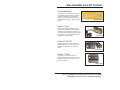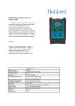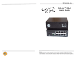
1
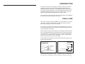
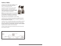
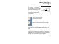
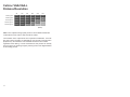
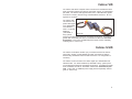
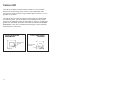
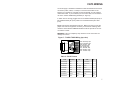
SP Controls, Inc
CatLinc™
User’s Manual
CatLinc™
CatLinc™
CatLinc™
CatLinc™
CatLinc™
SP Controls, Inc.
601 Minnesota Street, Suite 115
San Francisco, CA 94107
(877) 367-8444 toll free
(415) 642 2605 fax
VGA
VGA-L
VID
S-VID
HD
Caution:
This equipment does not allow the distribution of computer signals
through Ethernet networking hubs or switches. Do not connect this
device to a network hub or other communications equipment.
IMPORTANT SAFETY INSTRUCTIONS
1) Read these instructions. 2) Keep these instructions.
3) Heed all warnings.
4) Follow all instructions.
5) Do not use this apparatus near water.
6) Clean only with dry cloth. 7) Do not block any ventilation openings. Install in accordance with the
manufacturer's instructions. 8) Do not install near any heat sources such as radiators, heat registers,
stoves, or other apparatus (including amplifiers) that produce heat. 9) Protect the power cord from being walked on or pinched particularly at
plugs, convenience receptacles, and the point where they exit from the
apparatus. 10) Only use attachments/accessories specified by the manufacturer. 11) Unplug this apparatus during lightning storms or when unused for long
periods of time. 12) Refer all servicing to qualified service personnel. Servicing is required
when the apparatus has been damaged in any way, such as power-supply
cord or plug is damaged, liquid has been spilled or objects have fallen into
the apparatus, the apparatus has been exposed to rain or moisture, does
not operate normally, or has been dropped. Also Available from SP Controls
The SmartPanel™
The heart of the SP Controls product line,
the SmartPanel provides simple, intuitive
control for hundreds of LCD projectors.
Allows any user to take charge of today’s
presentation technology ... at the push of a
button.
SP2-SMCHAS-AG
CatLinc™ Net
CatLinc Net is a compact Ethernet web
server control interface for the SmartPanel.
Provides remote control and monitoring of
any SmartPanel-controlled projector, as well
as enhanced security and maintenance. No
programming - plug and play!
CatLinc NET
CatLinc™ RS-232
CatLinc RS-232 is a low-cost solution for
extending RS-232 runs. This product can
safely transmit RS-232 over CAT5 up to
1000m.
Cat:Linc RS-232
CatLinc™ DA-8
The CatLinc 1x8 CAT5 Distribution
Amplifier. Splits the signal from one CatLinc
Transmitter of any type to as many as 8
CatLinc Receivers.
Cat:Linc DA-8
Visit our website at www.spcontrols.com or contact
[email protected] for more information.
INTRODUCTION
WARRANTY
SP Controls warrants all CatLinc products and accessories against defects
in materials and workmanship for a period of three years from the date of
purchase.
Although SP Controls thoroughly tested and reviewed this documentation,
there is no warranty, express or implied, with respect to quality, merchantability, or fitness for a particular purpose. Therefore, the CatLinc and
accessories are provided “as-is” and the purchaser assumes the entire risk
as to quality and performance.
There are no obligations or liabilities on the part of the SP Controls
Corporation for consequential damages arising out of or in conjunction with
the use or performance of these products or other indirect damages with
respect to loss of profit, revenue, or cost of removal and/or replacement.
Some states do not allow the exclusion or limitation of incidental or consequential damages, so the above limitation or exclusion may not apply to you.
This warranty gives you specific legal rights, and you may also have other
rights that vary from state to state. SP Controls’ maximum liability shall not
exceed the price paid by the user.
All implied warranties, including warranties for merchantability and/or fitness,
are limited in duration to three (3) years from the date of purchase. Proof of
purchase must be provided with any claim.
The CatLinc™ family of products allows connection between two devices*
utilizing CAT5, CAT5e, or CAT6 shielded twisted pair cable (STP), foil
shielded twisted pair cable (FTP), or unshielded twisted pair cable (UTP). It
is strongly recommended that you use shielded twisted pair cable (STP) or
foil shielded twisted pair cable (FTP) with your CatLinc product, such as
standard, off-the-shelf preterminated CAT5 networking cable.
The Transmitter and Receiver units have been designed for easy installation
and they are among the smallest in the industry.
CatLinc VGA
The CatLinc VGA allows VGA (or RGBHV) connection between two devices
using CAT5, CAT5e, or CAT6 twisted pair cable. Connection is made to
devices using standard male HD-15 connectors.
The CatLinc VGA Transmitter actively buffers and amplifies the source sig
nal, eliminating the need for the interfaces or distribution amplifiers that are
often required with VGA signals.
CatLinc VGA can extend a VGA signal up to 91m/300ft over standard CAT5
cable. At typical distances this product will provide excellent image quality
for all resolutions. It can be used for longer runs, but the image quality may
be reduced. A Distance/Resolution chart (Page 4, Table 1) indicates sup
ported resolutions based on CAT5 cable length.
A single screwdriver adjustment at the Receiver allows fine-tuning for best
picture detail (see page 3).
CatLinc VGA/VGA-L
TRANSMITTER
CatLinc VGA/VGA-L
RECEIVER
INDICATES VIDEO
IS PRESENT
INDICATES SIGNAL
IS PRESENT
DETAIL ADJUSTMENT
(Figure 1)
( i
)
INDICATES POWER
IS PRESENT
INDICATES POWER IS PRESENT
(Figure 2)
*Exception: the CatLinc VGA-L can connect three devices. Also, any Catlinc signal
can be split from on Transmitter to as many as 8 Receivers using the CatLinc DA-8.
16
1
CatLinc VGA-L
FCC COMPLIANCE
The CatLinc VGA-L allows VGA (or RGBHV) connec
tion between two or three devices using CAT5,
CAT5e, or CAT6 twisted pair cable.
This equipment generates radio frequency energy and if not installed in
accordance with the manufacturer’s instructions may cause radio interference.
Connection is made to devices using a standard
male HD-15 connector. The CatLinc VGA-L
Transmitter provides a local loop-back female VGA
cable to split the signal to a local display in addition
to the CAT5 connection to the Receiver.
This equipment complies with part 15, Subpart J of the FCC rules for a
Class A computing device. This equipment also complies with the Class A
limits for radio noise emission from digital apparatus set out in the Radio
Interference Regulation of the Canadian Department of Communications.
These above rules are designed to provide reasonable protection against
such interference when operating the equipment in a commercial environment. If operation of this equipment in a residential area causes radio frequency interference, the user and not SP Controls, Inc., will be responsible.
NOTE: the local loop-back VGA must be terminated
or the VGA signal will be affected. If you do not have
CatLinc VGA-L
a second device, a male VGA 75 ohm terminating
plug can be used. A terminating plug can be sepa
rately ordered from SP Controls (part no. CatLinc TERM).
The CatLinc VGA -L Transmitter actively buffers and amplifies the source
signal, eliminating the need for the interfaces or distribution amplifiers that
are often required with VGA signals.
Changes or modifications made to this equipment not expressly approved
by SP Controls, Inc., could void the user’s authority to operate the equipment.
SP Controls, Inc. assumes no responsibility for any errors that appear in this
document. Information in this document is subject to change without notice.
The CatLinc VGA -L can extend a VGA signal up to 91m/300ft over standard
CAT5 cable. At typical distances this product will provide excellent image
quality for all resolutions. It can be used for longer runs, but the image qual
ity may be reduced. A Distance/Resolution chart (Page 4, Table 1) indicates
supported resolutions based on CAT5 cable length.
A single screwdriver adjustment at the Receiver allows fine-tuning for best
picture detail (see page 3).
Figure 3 - CatLinc VGA-L Connection
COPYRIGHT
CatLinc™, SmartPanel™, and the SP Controls switch logo are trademarks
of SP Controls, Inc. No part of this document may be reproduced or transmitted in any form or by any means, electronic or mechanical, for any purpose, without express written permission of SP Controls, Inc.
© 2003 SP Controls, Inc. All rights reserved.
2
15
TECHNICAL SPECIFICATIONS Cont.’d
Video Output cont.’d
Connectors
CatLinc VGA
CatLinc VGA-L
CatLinc VID
CatLinc S-VID
CatLinc HD
Nominal Level
CatLinc VGA/VGA-L
CatLinc VID
CatLinc S-VID
CatLinc HD
Minimum/Maximum levels
CatLinc VGA/VGA-L
CatLinc VID/S-VID/HD
Impedance
Audio - CatLinc VID only
Connectors
Gain
Frequency response (-3dB)
Input impedance
Output impedance
THD+N @ 0dBu
Max level in
Output clip level
Output Noise
Cross-talk
Dynamic range
Signal-to-noise ratio (min)
Size
1 male HD-15, RJ-45
1 male HD-15, 1 female
HD-15 (loop), RJ-45
3 male RCA, RJ-45
3 male RCA, RJ-45
3 male RCA, RJ-45
0.7V p-p
1V p-p
Y: 1V p-p, C: 0.3V p-p
Y: 1V p-p, PB(CB): 0.7V p-p,
PR(CR): 0.7V p-p
0.3V to 5V p-p
0.3V to 1.5V p-p
75 ohms
2 male RCA
Unity
2Hz - 100 kHz
20 kOhms
75 Ohms
0.008%
+10.5dBu
-86dBu
-86dBu
-78dBu
95dB
95dB
Metal housing: 2.5"(L) x 1.15"(W) x
0.95"(H)
Cable Length (approx.)
CatLinc VGA/VGA-L
CatLinc VID
CatLinc S-VID
CatLinc HD
VGA 6"
RCA 9”
mini-DIN 9”
RCA 9”
Shipping Weight
2.0 lb.
Optional Accessories
CatLinc PS (additional power supply for
CatLinc VID/S-VID/HD)
CatLinc TERM (75 ohm male VGA
termination plug for CatLinc VGA-L)
14
CatLinc VGA/VGA-L
Detail Adjust
Calibrate Detail Adjustment to find the opti
mal balance point that avoids two possible
types of distortion. The images below
show display artifacts you may see if Detail
Adjustment is not set properly. For adjustment, open any window on the source
computer against a solid background.
Adjustment is performed by turning the
Detail Adjust screw with the included
2.5mm screwdriver.
Figure 4 - Detail Adjust
DETAIL
ADJUSTMENT
Adjust 2.5mm screw
for best picture
CatLinc VGA/VGA-L Receiver
Look at the lower right hand corner of any window.
If there is a lighter shadow after it,
turn the Detail Adjust clockwise.
If there is a darker streaking trailing the corner
of the window, turn the Detail Adjust counter-clockwise.
NOTE: Depending on cable length, adjustment direction may vary. Any time
the CAT5 cable length is changed the Detail Adjust will need to be recali
brated.
No adjustment is necessary for CatLinc VID, S-VID, or HD.
For best picture, the computer should be matched to the native resolution of
the display being used. A 60 Hz refresh rate is best for any digital output
device. See your PC documentation/Help for more information.
3
CatLinc VGA/VGA-L
Distance/Resolution
TECHNICAL SPECIFICATIONS
50ft
100ft
150ft
200ft
250ft
300ft
640x480 @ 60 Hz
excellent
excellent
excellent
excellent
excellent
excellent
800x600 @ 60 Hz
excellent
excellent
excellent
excellent
excellent
fair
1024x768 @ 60 Hz
excellent
excellent
excellent
excellent
fair
fair
1280x1024 @ 60 Hz
excellent
excellent
excellent
fair
fair
poor
1600x1200 @ 60 Hz
excellent
excellent
fair
fair
poor
poor
(Table 1)
Table 1 is a subjective image quality chart for various distance/resolution
combinations for the CatLinc VGA and CatLinc VGA-L.
The resolution of the output device is an important consideration. If the dis
play has a native resolution of 1024x768 (as most of today’s LCD and DLP
projectors do), all resolutions over 1024x768 will have a loss of detail
regardless of the cabling. In these circumstances, this product can actually
help to improve the resulting image by reducing some of the digital artifacts
of the scaling process.
Power
9 VDC@030 mA UL Approved
Power Connector
3.5mm O.D./1.3mm I.D. Center pos
Power Connector Requirements
1 power supply (either end)
CatLinc VGA/VGA-L @ 0-300ft/0-91m
CatLinc VID/S-VID/HD @ 0-350ft/0-110m 1 power supply (either end)
CatLinc VID/S-VID/HD @
2 power supplies (both ends)
351-1200ft/110m-365m
Video
Gain
Video input
Signal type
CatLinc VGA/VGA-L
CatLinc VID
CatLinc S-VID
CatLinc HD
Connectors
CatLinc VGA/VGA-L
CatLinc VID
CatLinc S-VID
CatLinc HD
Nominal Level
CatLinc VGA/VGA-L
CatLinc VID
CatLinc S-VID
CatLinc HD
Minimum/Maximum levels
CatLinc VGA/VGA-L
CatLinc VID/S-VID/HD
Impedance
Sync
CatLinc VGA/VGA-L
CatLinc VID
CatLinc S-VID
CatLinc HD
Video Output
Signal type
CatLinc VGA/VGA-L
CatLinc VID
CatLinc S-VID
CatLinc HD
4
Unity
Analog VGA
Composite video
S-Video
Component video
1
3
3
3
male
male
male
male
HD-15, RJ-45
RCA, RJ-45
RCA, RJ-45
RCA, RJ-45
0.7V p-p
1.0V p-p
Y: 1.0V p-p, C: 0.3V p-p
Y: 1.0V p-p, PB(CB): 0.7V p-p,
PR(CR): 0.7V p-p
0.3V to 5V p-p
0.3V to 1.5V p-p
75 ohms
TTL Compatible + or - polarity
NTSC 3.58, NTSC 4.43, PAL, SECAM
NTSC 3.58, NTSC 4.43, PAL, SECAM
NTSC 3.58, NTSC 4.43, PAL, SECAM
Analog VGA
Composite video
S-Video
Component video
13
TROUBLESHOOTING Cont.’d
Image is Distorted:
-CatLinc HD: Verify that the video signal input on the CatLinc Receiver
matches the video signal output on the CatLinc Transmitter end. For example, if Y (Luminance) is wired to Green RCA on the CatLinc Transmitter, the
Green RCA of the Receiver should be connected to the Y signal input on the
projector or
Image is Too Bright:
-CatLinc VID: Be sure the video signal is connected to the CatLinc
Receiver RCA input labeled VIDEO. Do not pass video through the audio
channels.
-CatLinc VGA-L: Be sure that the local loop-back cable is properly terminated at a second display device. If the loop-back VGA is not terminated, the
signal will be excessively bright. If you do not have a second display
device, a male VGA 75 ohm terminating plug can also be used (SP Controls
part no. CatLinc TERM).
Image Color is Not Correct:
-All Units: If the image is missing a color and you have confirmed that the
CAT5 cable is terminated properly, it may be the case that an improperly
crimped RJ-45 connector was inserted into the unit. If you terminated the
cables, verify that the contacts have been properly pushed down.
-CatLinc VGA/VGA-L: If one of the pairs in the CAT5 cable is not terminated properly in the RJ-45 connector, one of the colors (red, green, blue) may
not work. Try a different CAT5 cable or re-terminate the cable. Verify that the
cable and plug pinout agrees with the illustration in the CAT5 Wiring section
(pg. 7).
CatLinc Units Grow Warm:
CatLinc VID
The CatLinc VID allows composite video connection and unbalanced stereo
audio connection between two devices using CAT5, CAT5e, or CAT6 twisted
pair cable. The CatLinc VID supports NTSC, PAL, or SECAM video signals.
Connection is made to devices using 3 standard RCA connectors. No con
figuration is necessary.
The CatLinc VID
can extend a com
posite video signal
up to 365m/1200ft
over standard
CAT5. For shorter
distances
(110m/350ft or
CatLinc VID
less), system
power may be attached at either the Transmitter or Receiver. For distances
greater than 110m/350ft, the CatLinc Transmitter and Receiver must both
be powered. In this case, an additional power supply must be separately
ordered (part no. CatLinc PS).
CatLinc S-VID
The CatLinc S-VID allows S-Video (YC) connection between two devices
using CAT5, CAT5e, or CAT6 twisted pair cable. Connection is made to
devices using standard S-Video mini-DIN connectors. No configuration is
necessary.
The CatLinc S-VID can extend an S-Video signal up to 365m/1200ft over
standard CAT5. For shorter distances (110m/350ft or less), system power
may be attached at either the Transmitter or Receiver. For distances greater
than 110m/350ft, the CatLinc Transmitter and Receiver must both be pow
ered. In this case, an additional power supply must be separately ordered
(part no. CatLinc PS).
-All Units: CatLinc Transmitters and Receivers typically run at a fairly warm
temperature during normal operation. This will not damage the units.
However, they should not become too hot to touch during normal operation.
If a CatLinc becomes unusually hot, unplug the unit and contact SP Controls
Technical Support.
12
5
TROUBLESHOOTING
CatLinc HD
The CatLinc HD allows component video (Y/Pb/Pr or YUV) connection
between two devices using CAT5, CAT5e, or CAT6 twisted pair cable.
Connection is made to devices using 3 standard RCA connectors. No con
figuration is necessary.
The CatLinc HD can extend a component video signal up to 365m/1200ft
over standard CAT5. For shorter distances (110m/350ft or less), system
power may be attached at either the Transmitter or Receiver. For distances
greater than 110m/350ft, the CatLinc Transmitter and Receiver must both
be powered. In this case, an additional power supply must be separately
ordered (part no. CatLinc PS).
CatLinc VID/S-VID/HD
TRANSMITTER
CatLinc VID/S-VID/HD
RECEIVER
-All Units: Verify that the unit at the source (VCR, computer, et cetera) is
the Transmitter and the unit at the destination (projector or monitor) is the
Receiver.
- All Units: Verify that your video device is properly sending an active signal. Note: Most Laptops need to be configured to export an extrenal VGA
signal.
-All Units: Ensure that the power supply is plugged in and that the Power
indicator is lit on both the Transmitter and the Receiver.
-CatLinc VGA/VGA-L: ensure that the Signal LED is lit on both the
Transmitter and the Receiver. If the Signal LED is not lit on the Transmitter,
the laptop may not be exporting the VGA signal. If the Signal LED is not lit
on the receiver, check the cabling.
-CatLinc VID/S-VID/HD: Verify that the connection landings on the
Transmitter agree with the connection landings on the Receiver unit. For
example, for CatLinc HD if the Y signal out on the display device is connected to the green CatLinc RCA on the Transmitter, the green CatLinc RCA on
the Receiver must be connected to the Y signal input on the display device.
INDICATES POWER
IS PRESENT
INDICATES POWER
IS PRESENT
(Figure 5)
No Picture:
(Figure 6)
-CatLinc VID/S-VID/HD: in CAT5 runs exceeding 110m/350ft in length, be
sure that both the Transmitter and Receiver units are powered. Additional
power supplies can be ordered from SP Controls (part no. CatLinc PS).
Poor Image Quality:
-All Units: Verify that all components and cables are plugged in securely.
-All Units: Check computer settings for scan rate and refresh rate. Most
LCD/DLP projectors work fine with a scan rate of 60 Hz. Changing to 60Hz
may improve the image. A higher scan rate will not improve image quality of
LCD/DLP projectors.
CatLinc VGA/VGA-L: Ensure that the Detail Adjustment procedure has
been followed (see pg. 3). For optimal image quality, set the refresh
6
rate of your video device to 60Hz. Also, check to make sure that the
resolution of your display device matches the resolution of your
video source
11
CAT5 WIRING
CONNECTING THE TRANSMITTER Cont.’d
CatLinc HD
1) Attach the 3 RCA connectors labeled SOURCE on the Transmitter to the
Composite Video output (e.g., Y,PB,PR) port on the source device. Standard
wiring convention is: Green RCA to Y, Red to Pr/U, Blue to PB/V.
2) Attach one end of the CAT5 cable into the RJ-45 jack labeled CAT5 on
the Transmitter.
3) Mount the device anywhere with the Velcro strips provided.
CONNECTING THE RECEIVER
1) Attach the other end of the CAT5 cable to the CatLinc Receiver in the RJ45 jack labeled CAT5.
You must supply a standard 4-Twisted Pair cable terminated with two RJ-45
connectors (CAT5, CAT5e, or CAT6) to connect the Transmitter to the
Receiver. For easiest use it is highly recommended that you use pretermi
nated CAT5 cable. If you terminate your own CAT5 cable, we recommend
use of the TIA-EIA T568B wiring standard (Cf. Figure 2).
In either case we strongly suggest the use of shielded twisted pair (STP) or
foil shielded twisted pair (FTP) cable over unshielded twisted pair cable
(UTP).
Figure 7 shows the preferred RJ-45 pinout. Make sure that you have the
proper tools and test equipment necessary to test that the resulting cable
meets the CAT5 standard. Table 2 indicates the RJ-45 pinouts for the vari
ous CatLinc models.
WARNING: Failure to completely crimp down the RJ-45 connectors can
damage the CatLinc.
Figure
7 -7TIA-EIA
T568BWiring
Wiring
Figure
- TIA-EIA T568B
(top (top
view) view)
2) Attach the 15 pin HD D-sub, mini-DIN, or RCA connectors labeled
DESTINATION (illustrated with an icon showing a monitor and a
projector) on the CatLinc Receiver to the appropriate input port on the monitor or video projector.
White Base/Orange Stripe
Orange Base/White Stripe
White Base/Green Stripe
Blue Base/White Stripe
White Base/Blue Stripe
Green Base/White Stripe
White Base/Brown Stripe
Brown Base/White Stripe
3) For the CatLinc VGA/VGA-L the 9-Volt DC Power Supply may be
attached at either the Transmitter or the Receiver to the jack labeled DC
Power In.
For the CatLinc VID, CatLinc S-VID, or CatLinc HD, if your cable length
exceeds 110m (350ft), the CatLinc must be powered at both the Transmitter
and Receiver ends.
4) Once the devices are connected and power is applied to one or more
units, the you should see the POWER Led illuminate on both the Transmitter
and Receiver.
For the CatLinc VGA/VGA-L, when the Transmitter and Receiver are connected and the system is powered, you should see the SIGNAL LED illuminate.
NOTE: It is normal for the Transmitter and Receiver units to become warm
during operation.
10
Table 2 - RJ-45 Pinouts
RJ-45
VGA/VGA-L
VID
S-VID
HD
1) White/Orange
Red
VID
Y (Luminance)
Y
2) Orange/White
Red
VID
Y (Luminance)
Y
3) White/Green
Blue
Audio Right
unused
Pb
6) Green/White
Blue
Audio Right
unused
Pb
4) Blue/White
Green
Audio Left
C (Chrominance)
Pr
5) White/Blue
Green
Audio Left
C (Chrominance)
Pr
7) White/Brown
+9VDC
+9VDC
+9VDC
+9VDC
8) Brown/White
GND
GND
GND
GND
7
CONNECTING THE TRANSMITTER Cont.’d
CONNECTING THE TRANSMITTER
CatLinc VGA-L
1) Connect the Transmitter 15-pin male HD D-sub connector with the COMPUTER icon to the VGA output port on the laptop or computer.
2) Attach the 15-pin female HD D-sub connector with the MONITOR icon on
the Transmitter to a VGA cable, or terminate with a male 75 ohm VGA plug
(the loopback must be terminated). Connect the other end of the VGA cable
to the VGA input of your local monitor.
3) Attach one end of the CAT5 cable into the RJ-45 jack labeled CAT5 on
the Transmitter.
4) Mount the device anywhere with the Velcro strips provided.
5) Set your PC or laptop to export the VGA signal (settings vary - refer to
your PC documenation or Help for more information).
CatLinc VID
(Figure 8 - Typical CatLinc VGA Connection)
CatLinc VGA
1) Connect the 15 pin HD D-sub connector labeled SOURCE on the
Transmitter to the VGA output port on the laptop or computer.
1) Connect the yellow RCA connector labeled VIDEO on the Transmitter to
the RCA video output port on the VCR or video device.
2) Connect stereo audio from the source device to the red (right channel)
and white (left channel) RCA’s labeled AUDIO on the transmitter.
3) Attach one end of the CAT5 cable into the RJ-45 jack labeled CAT5 on
the Transmitter.
2) Attach one end of the CAT5 cable into the RJ-45 jack labeled CAT5 on
the Transmitter.
4) Mount the device anywhere with the Velcro strips provided.
3) Mount the device anywhere with the Velcro strips provided.
CatLinc S-VID
4) Set your PC or laptop to export the VGA signal (settings vary - refer to
your PC documenation or Help for more information).
1) Connect the mini-DIN connector labeled SOURCE on the Transmitter to
the S-Video mini-DIN output port on the DVD Player or video source.
2) Attach one end of the CAT5 cable into the RJ-45 jack labeled CAT5 on
the Transmitter.
3) Mount the device anywhere with the Velcro strips provided.
8
9
CONNECTING THE TRANSMITTER Cont.’d
CONNECTING THE TRANSMITTER
CatLinc VGA-L
1) Connect the Transmitter 15-pin male HD D-sub connector with the COM
PUTER icon to the VGA output port on the laptop or computer.
2) Attach the 15-pin female HD D-sub connector with the MONITOR icon on
the Transmitter to a VGA cable, or terminate with a male 75 ohm VGA plug
(the loopback must be terminated). Connect the other end of the VGA cable
to the VGA input of your local monitor.
3) Attach one end of the CAT5 cable into the RJ-45 jack labeled CAT5 on
the Transmitter.
4) Mount the device anywhere with the Velcro strips provided.
5) Set your PC or laptop to export the VGA signal (settings vary - refer to
your PC documenation or Help for more information).
CatLinc VID
(Figure 8 - Typical CatLinc VGA Connection)
CatLinc VGA
1) Connect the 15 pin HD D-sub connector labeled SOURCE on the
Transmitter to the VGA output port on the laptop or computer.
1) Connect the yellow RCA connector labeled VIDEO on the Transmitter to
the RCA video output port on the VCR or video device.
2) Connect stereo audio from the source device to the red (right channel)
and white (left channel) RCA’s labeled AUDIO on the transmitter.
3) Attach one end of the CAT5 cable into the RJ-45 jack labeled CAT5 on
the Transmitter.
2) Attach one end of the CAT5 cable into the RJ-45 jack labeled CAT5 on
the Transmitter.
4) Mount the device anywhere with the Velcro strips provided.
3) Mount the device anywhere with the Velcro strips provided.
CatLinc S-VID
4) Set your PC or laptop to export the VGA signal (settings vary - refer to
your PC documenation or Help for more information).
1) Connect the mini-DIN connector labeled SOURCE on the Transmitter to
the S-Video mini-DIN output port on the DVD Player or video source.
2) Attach one end of the CAT5 cable into the RJ-45 jack labeled CAT5 on
the Transmitter.
3) Mount the device anywhere with the Velcro strips provided.
8
9
CAT5 WIRING
CONNECTING THE TRANSMITTER Cont.’d
CatLinc HD
1) Attach the 3 RCA connectors labeled SOURCE on the Transmitter to the
Composite Video output (e.g., Y,PB,PR) port on the source device. Standard
wiring convention is: Green RCA to Y, Red to Pr/U, Blue to PB/V.
2) Attach one end of the CAT5 cable into the RJ-45 jack labeled CAT5 on
the Transmitter.
3) Mount the device anywhere with the Velcro strips provided.
CONNECTING THE RECEIVER
1) Attach the other end of the CAT5 cable to the CatLinc Receiver in the RJ
45 jack labeled CAT5.
You must supply a standard 4-Twisted Pair cable terminated with two RJ-45
connectors (CAT5, CAT5e, or CAT6) to connect the Transmitter to the
Receiver. For easiest use it is highly recommended that you use preterminated CAT5 cable. If you terminate your own CAT5 cable, we recommend
use of the TIA-EIA T568B wiring standard (Cf. Figure 2).
In either case we strongly suggest the use of shielded twisted pair (STP) or
foil shielded twisted pair (FTP) cable over unshielded twisted pair cable
(UTP).
Figure 7 shows the preferred RJ-45 pinout. Make sure that you have the
proper tools and test equipment necessary to test that the resulting cable
meets the CAT5 standard. Table 2 indicates the RJ-45 pinouts for the various CatLinc models.
WARNING: Failure to completely crimp down the RJ-45 connectors can
damage the CatLinc.
Figure
7 -7TIA-EIA
T568BWiring
Wiring
Figure
- TIA-EIA T568B
(top (top
view) view)
2) Attach the 15 pin HD D-sub, mini-DIN, or RCA connectors labeled
DESTINATION (illustrated with an icon showing a monitor and a
projector) on the CatLinc Receiver to the appropriate input port on the moni
tor or video projector.
White Base/Orange Stripe
Orange Base/White Stripe
White Base/Green Stripe
Blue Base/White Stripe
White Base/Blue Stripe
Green Base/White Stripe
White Base/Brown Stripe
Brown Base/White Stripe
3) For the CatLinc VGA/VGA-L the 9-Volt DC Power Supply may be
attached at either the Transmitter or the Receiver to the jack labeled DC
Power In.
For the CatLinc VID, CatLinc S-VID, or CatLinc HD, if your cable length
exceeds 110m (350ft), the CatLinc must be powered at both the Transmitter
and Receiver ends.
4) Once the devices are connected and power is applied to one or more
units, the you should see the POWER Led illuminate on both the Transmitter
and Receiver.
For the CatLinc VGA/VGA-L, when the Transmitter and Receiver are con
nected and the system is powered, you should see the SIGNAL LED illumi
nate.
NOTE: It is normal for the Transmitter and Receiver units to become warm
during operation.
10
Table 2 - RJ-45 Pinouts
RJ-45
VGA/VGA-L
VID
S-VID
HD
1) White/Orange
Red
VID
Y (Luminance)
Y
2) Orange/White
Red
VID
Y (Luminance)
Y
3) White/Green
Blue
Audio Right
unused
Pb
6) Green/White
Blue
Audio Right
unused
Pb
4) Blue/White
Green
Audio Left
C (Chrominance)
Pr
5) White/Blue
Green
Audio Left
C (Chrominance)
Pr
7) White/Brown
+9VDC
+9VDC
+9VDC
+9VDC
8) Brown/White
GND
GND
GND
GND
7
TROUBLESHOOTING
CatLinc HD
The CatLinc HD allows component video (Y/Pb/Pr or YUV) connection
between two devices using CAT5, CAT5e, or CAT6 twisted pair cable.
Connection is made to devices using 3 standard RCA connectors. No configuration is necessary.
The CatLinc HD can extend a component video signal up to 365m/1200ft
over standard CAT5. For shorter distances (110m/350ft or less), system
power may be attached at either the Transmitter or Receiver. For distances
greater than 110m/350ft, the CatLinc Transmitter and Receiver must both
be powered. In this case, an additional power supply must be separately
ordered (part no. CatLinc PS).
CatLinc VID/S-VID/HD
TRANSMITTER
CatLinc VID/S-VID/HD
RECEIVER
-All Units: Verify that the unit at the source (VCR, computer, et cetera) is
the Transmitter and the unit at the destination (projector or monitor) is the
Receiver.
- All Units: Verify that your video device is properly sending an active sig
nal. Note: Most Laptops need to be configured to export an extrenal VGA
signal.
-All Units: Ensure that the power supply is plugged in and that the Power
indicator is lit on both the Transmitter and the Receiver.
-CatLinc VGA/VGA-L: ensure that the Signal LED is lit on both the
Transmitter and the Receiver. If the Signal LED is not lit on the Transmitter,
the laptop may not be exporting the VGA signal. If the Signal LED is not lit
on the receiver, check the cabling.
-CatLinc VID/S-VID/HD: Verify that the connection landings on the
Transmitter agree with the connection landings on the Receiver unit. For
example, for CatLinc HD if the Y signal out on the display device is connect
ed to the green CatLinc RCA on the Transmitter, the green CatLinc RCA on
the Receiver must be connected to the Y signal input on the display device.
INDICATES POWER
IS PRESENT
INDICATES POWER
IS PRESENT
(Figure 5)
No Picture:
(Figure 6)
-CatLinc VID/S-VID/HD: in CAT5 runs exceeding 110m/350ft in length, be
sure that both the Transmitter and Receiver units are powered. Additional
power supplies can be ordered from SP Controls (part no. CatLinc PS).
Poor Image Quality:
-All Units: Verify that all components and cables are plugged in securely.
-All Units: Check computer settings for scan rate and refresh rate. Most
LCD/DLP projectors work fine with a scan rate of 60 Hz. Changing to 60Hz
may improve the image. A higher scan rate will not improve image quality of
LCD/DLP projectors.
CatLinc VGA/VGA-L: Ensure that the Detail Adjustment procedure has
been followed (see pg. 3). For optimal image quality, set the refresh
6
rate of your video device to 60Hz. Also, check to make sure that the
resolution of your display device matches the resolution of your
video source
11
TROUBLESHOOTING Cont.’d
Image is Distorted:
-CatLinc HD: Verify that the video signal input on the CatLinc Receiver
matches the video signal output on the CatLinc Transmitter end. For exam
ple, if Y (Luminance) is wired to Green RCA on the CatLinc Transmitter, the
Green RCA of the Receiver should be connected to the Y signal input on the
projector or
Image is Too Bright:
-CatLinc VID: Be sure the video signal is connected to the CatLinc
Receiver RCA input labeled VIDEO. Do not pass video through the audio
channels.
-CatLinc VGA-L: Be sure that the local loop-back cable is properly terminat
ed at a second display device. If the loop-back VGA is not terminated, the
signal will be excessively bright. If you do not have a second display
device, a male VGA 75 ohm terminating plug can also be used (SP Controls
part no. CatLinc TERM).
Image Color is Not Correct:
-All Units: If the image is missing a color and you have confirmed that the
CAT5 cable is terminated properly, it may be the case that an improperly
crimped RJ-45 connector was inserted into the unit. If you terminated the
cables, verify that the contacts have been properly pushed down.
-CatLinc VGA/VGA-L: If one of the pairs in the CAT5 cable is not terminat
ed properly in the RJ-45 connector, one of the colors (red, green, blue) may
not work. Try a different CAT5 cable or re-terminate the cable. Verify that the
cable and plug pinout agrees with the illustration in the CAT5 Wiring section
(pg. 7).
CatLinc Units Grow Warm:
CatLinc VID
The CatLinc VID allows composite video connection and unbalanced stereo
audio connection between two devices using CAT5, CAT5e, or CAT6 twisted
pair cable. The CatLinc VID supports NTSC, PAL, or SECAM video signals.
Connection is made to devices using 3 standard RCA connectors. No configuration is necessary.
The CatLinc VID
can extend a composite video signal
up to 365m/1200ft
over standard
CAT5. For shorter
distances
(110m/350ft or
CatLinc VID
less), system
power may be attached at either the Transmitter or Receiver. For distances
greater than 110m/350ft, the CatLinc Transmitter and Receiver must both
be powered. In this case, an additional power supply must be separately
ordered (part no. CatLinc PS).
CatLinc S-VID
The CatLinc S-VID allows S-Video (YC) connection between two devices
using CAT5, CAT5e, or CAT6 twisted pair cable. Connection is made to
devices using standard S-Video mini-DIN connectors. No configuration is
necessary.
The CatLinc S-VID can extend an S-Video signal up to 365m/1200ft over
standard CAT5. For shorter distances (110m/350ft or less), system power
may be attached at either the Transmitter or Receiver. For distances greater
than 110m/350ft, the CatLinc Transmitter and Receiver must both be powered. In this case, an additional power supply must be separately ordered
(part no. CatLinc PS).
-All Units: CatLinc Transmitters and Receivers typically run at a fairly warm
temperature during normal operation. This will not damage the units.
However, they should not become too hot to touch during normal operation.
If a CatLinc becomes unusually hot, unplug the unit and contact SP Controls
Technical Support.
12
5
CatLinc VGA/VGA-L
Distance/Resolution
TECHNICAL SPECIFICATIONS
50ft
100ft
150ft
200ft
250ft
300ft
640x480 @ 60 Hz
excellent
excellent
excellent
excellent
excellent
excellent
800x600 @ 60 Hz
excellent
excellent
excellent
excellent
excellent
fair
1024x768 @ 60 Hz
excellent
excellent
excellent
excellent
fair
fair
1280x1024 @ 60 Hz
excellent
excellent
excellent
fair
fair
poor
1600x1200 @ 60 Hz
excellent
excellent
fair
fair
poor
poor
(Table 1)
Table 1 is a subjective image quality chart for various distance/resolution
combinations for the CatLinc VGA and CatLinc VGA-L.
The resolution of the output device is an important consideration. If the display has a native resolution of 1024x768 (as most of today’s LCD and DLP
projectors do), all resolutions over 1024x768 will have a loss of detail
regardless of the cabling. In these circumstances, this product can actually
help to improve the resulting image by reducing some of the digital artifacts
of the scaling process.
Power
9 VDC@030 mA UL Approved
Power Connector
3.5mm O.D./1.3mm I.D. Center pos
Power Connector Requirements
1 power supply (either end)
CatLinc VGA/VGA-L @ 0-300ft/0-91m
CatLinc VID/S-VID/HD @ 0-350ft/0-110m 1 power supply (either end)
CatLinc VID/S-VID/HD @
2 power supplies (both ends)
351-1200ft/110m-365m
Video
Gain
Video input
Signal type
CatLinc VGA/VGA-L
CatLinc VID
CatLinc S-VID
CatLinc HD
Connectors
CatLinc VGA/VGA-L
CatLinc VID
CatLinc S-VID
CatLinc HD
Nominal Level
CatLinc VGA/VGA-L
CatLinc VID
CatLinc S-VID
CatLinc HD
Minimum/Maximum levels
CatLinc VGA/VGA-L
CatLinc VID/S-VID/HD Impedance
Sync
CatLinc VGA/VGA-L
CatLinc VID
CatLinc S-VID
CatLinc HD
Video Output
Signal type
CatLinc VGA/VGA-L
CatLinc VID
CatLinc S-VID
CatLinc HD
4
Unity
Analog VGA
Composite video
S-Video
Component video
1
3
3
3
male
male
male
male
HD-15, RJ-45
RCA, RJ-45
RCA, RJ-45
RCA, RJ-45
0.7V p-p
1.0V p-p
Y: 1.0V p-p, C: 0.3V p-p
Y: 1.0V p-p, PB(CB): 0.7V p-p,
PR(CR): 0.7V p-p
0.3V to 5V p-p
0.3V to 1.5V p-p
75 ohms
TTL Compatible + or - polarity
NTSC 3.58, NTSC 4.43, PAL, SECAM
NTSC 3.58, NTSC 4.43, PAL, SECAM
NTSC 3.58, NTSC 4.43, PAL, SECAM
Analog VGA
Composite video
S-Video
Component video
13
TECHNICAL SPECIFICATIONS Cont.’d
Video Output cont.’d
Connectors
CatLinc VGA
CatLinc VGA-L
CatLinc VID
CatLinc S-VID
CatLinc HD Nominal Level
CatLinc VGA/VGA-L
CatLinc VID
CatLinc S-VID
CatLinc HD
Minimum/Maximum levels
CatLinc VGA/VGA-L
CatLinc VID/S-VID/HD
Impedance
Audio - CatLinc VID only
Connectors
Gain
Frequency response (-3dB)
Input impedance
Output impedance
THD+N @ 0dBu
Max level in
Output clip level
Output Noise
Cross-talk
Dynamic range
Signal-to-noise ratio (min)
Size
1 male HD-15, RJ-45
1 male HD-15, 1 female
HD-15 (loop), RJ-45
3 male RCA, RJ-45
3 male RCA, RJ-45
3 male RCA, RJ-45
0.7V p-p
1V p-p
Y: 1V p-p, C: 0.3V p-p
Y: 1V p-p, PB(CB): 0.7V p-p,
PR(CR): 0.7V p-p
0.3V to 5V p-p
0.3V to 1.5V p-p
75 ohms
2 male RCA
Unity
2Hz - 100 kHz
20 kOhms
75 Ohms
0.008%
+10.5dBu
-86dBu
-86dBu
-78dBu
95dB
95dB
Metal housing: 2.5"(L) x 1.15"(W) x
0.95"(H)
Cable Length (approx.)
CatLinc VGA/VGA-L
CatLinc VID
CatLinc S-VID
CatLinc HD
VGA 6"
RCA 9”
mini-DIN 9”
RCA 9”
Shipping Weight
2.0 lb.
Optional Accessories
CatLinc PS (additional power supply for
CatLinc VID/S-VID/HD)
CatLinc TERM (75 ohm male VGA
termination plug for CatLinc VGA-L)
14
CatLinc VGA/VGA-L
Detail Adjust
Calibrate Detail Adjustment to find the optimal balance point that avoids two possible
types of distortion. The images below
show display artifacts you may see if Detail
Adjustment is not set properly. For adjustment, open any window on the source
computer against a solid background.
Adjustment is performed by turning the
Detail Adjust screw with the included
2.5mm screwdriver.
Figure 4 - Detail Adjust
DETAIL
ADJUSTMENT
Adjust 2.5mm screw
for best picture
CatLinc VGA/VGA-L Receiver
Look at the lower right hand corner of any window.
If there is a lighter shadow after it,
turn the Detail Adjust clockwise.
If there is a darker streaking trailing the corner
of the window, turn the Detail Adjust counter-clockwise.
NOTE: Depending on cable length, adjustment direction may vary. Any time
the CAT5 cable length is changed the Detail Adjust will need to be recalibrated.
No adjustment is necessary for CatLinc VID, S-VID, or HD.
For best picture, the computer should be matched to the native resolution of
the display being used. A 60 Hz refresh rate is best for any digital output
device. See your PC documentation/Help for more information.
3
CatLinc VGA-L
FCC COMPLIANCE
The CatLinc VGA-L allows VGA (or RGBHV) connection between two or three devices using CAT5,
CAT5e, or CAT6 twisted pair cable.
This equipment generates radio frequency energy and if not installed in
accordance with the manufacturer’s instructions may cause radio interfer
ence.
Connection is made to devices using a standard
male HD-15 connector. The CatLinc VGA-L
Transmitter provides a local loop-back female VGA
cable to split the signal to a local display in addition
to the CAT5 connection to the Receiver.
This equipment complies with part 15, Subpart J of the FCC rules for a
Class A computing device. This equipment also complies with the Class A
limits for radio noise emission from digital apparatus set out in the Radio
Interference Regulation of the Canadian Department of Communications.
These above rules are designed to provide reasonable protection against
such interference when operating the equipment in a commercial environ
ment. If operation of this equipment in a residential area causes radio fre
quency interference, the user and not SP Controls, Inc., will be responsible.
NOTE: the local loop-back VGA must be terminated
or the VGA signal will be affected. If you do not have
CatLinc VGA-L
a second device, a male VGA 75 ohm terminating
plug can be used. A terminating plug can be separately ordered from SP Controls (part no. CatLinc TERM).
The CatLinc VGA -L Transmitter actively buffers and amplifies the source
signal, eliminating the need for the interfaces or distribution amplifiers that
are often required with VGA signals.
Changes or modifications made to this equipment not expressly approved
by SP Controls, Inc., could void the user’s authority to operate the equip
ment.
SP Controls, Inc. assumes no responsibility for any errors that appear in this
document. Information in this document is subject to change without notice.
The CatLinc VGA -L can extend a VGA signal up to 91m/300ft over standard
CAT5 cable. At typical distances this product will provide excellent image
quality for all resolutions. It can be used for longer runs, but the image quality may be reduced. A Distance/Resolution chart (Page 4, Table 1) indicates
supported resolutions based on CAT5 cable length.
A single screwdriver adjustment at the Receiver allows fine-tuning for best
picture detail (see page 3).
Figure 3 - CatLinc VGA-L Connection
COPYRIGHT
CatLinc™, SmartPanel™, and the SP Controls switch logo are trademarks
of SP Controls, Inc. No part of this document may be reproduced or trans
mitted in any form or by any means, electronic or mechanical, for any pur
pose, without express written permission of SP Controls, Inc.
© 2010 SP Controls, Inc. All rights reserved.
2
15
INTRODUCTION
WARRANTY
SP Controls warrants all CatLinc products and accessories against defects
in materials and workmanship for a period of three years from the date of
purchase.
Although SP Controls thoroughly tested and reviewed this documentation,
there is no warranty, express or implied, with respect to quality, mer
chantability, or fitness for a particular purpose. Therefore, the CatLinc and
accessories are provided “as-is” and the purchaser assumes the entire risk
as to quality and performance.
There are no obligations or liabilities on the part of the SP Controls
Corporation for consequential damages arising out of or in conjunction with
the use or performance of these products or other indirect damages with
respect to loss of profit, revenue, or cost of removal and/or replacement.
Some states do not allow the exclusion or limitation of incidental or conse
quential damages, so the above limitation or exclusion may not apply to you.
This warranty gives you specific legal rights, and you may also have other
rights that vary from state to state. SP Controls’ maximum liability shall not
exceed the price paid by the user.
All implied warranties, including warranties for merchantability and/or fitness,
are limited in duration to three (3) years from the date of purchase. Proof of
purchase must be provided with any claim.
The CatLinc™ family of products allows connection between two devices*
utilizing CAT5, CAT5e, or CAT6 shielded twisted pair cable (STP), foil
shielded twisted pair cable (FTP), or unshielded twisted pair cable (UTP). It
is strongly recommended that you use shielded twisted pair cable (STP) or
foil shielded twisted pair cable (FTP) with your CatLinc product, such as
standard, off-the-shelf preterminated CAT5 networking cable.
The Transmitter and Receiver units have been designed for easy installation
and they are among the smallest in the industry.
CatLinc VGA
The CatLinc VGA allows VGA (or RGBHV) connection between two devices
using CAT5, CAT5e, or CAT6 twisted pair cable. Connection is made to
devices using standard male HD-15 connectors.
The CatLinc VGA Transmitter actively buffers and amplifies the source signal, eliminating the need for the interfaces or distribution amplifiers that are
often required with VGA signals.
CatLinc VGA can extend a VGA signal up to 91m/300ft over standard CAT5
cable. At typical distances this product will provide excellent image quality
for all resolutions. It can be used for longer runs, but the image quality may
be reduced. A Distance/Resolution chart (Page 4, Table 1) indicates supported resolutions based on CAT5 cable length.
A single screwdriver adjustment at the Receiver allows fine-tuning for best
picture detail (see page 3).
CatLinc VGA/VGA-L
TRANSMITTER
CatLinc VGA/VGA-L
RECEIVER
INDICATES VIDEO
IS PRESENT
INDICATES SIGNAL
IS PRESENT
DETAIL ADJUSTMENT
(Figure 1)
( i
)
INDICATES POWER
IS PRESENT
INDICATES POWER IS PRESENT
(Figure 2)
*Exception: the CatLinc VGA-L can connect three devices. Also, any Catlinc signal
can be split from on Transmitter to as many as 8 Receivers using the CatLinc DA-8.
16
1
IMPORTANT SAFETY INSTRUCTIONS
1) Read these instructions.
2) Keep these instructions.
3) Heed all warnings.
4) Follow all instructions.
5) Do not use this apparatus near water.
6) Clean only with dry cloth.
7) Do not block any ventilation openings. Install in accordance with the
manufacturer's instructions.
8) Do not install near any heat sources such as radiators, heat registers,
stoves, or other apparatus (including amplifiers) that produce heat.
9) Protect the power cord from being walked on or pinched particularly at
plugs, convenience receptacles, and the point where they exit from the
apparatus.
10) Only use attachments/accessories specified by the manufacturer.
11) Unplug this apparatus during lightning storms or when unused for long
periods of time.
12) Refer all servicing to qualified service personnel. Servicing is required
when the apparatus has been damaged in any way, such as power-supply
cord or plug is damaged, liquid has been spilled or objects have fallen into
the apparatus, the apparatus has been exposed to rain or moisture, does
not operate normally, or has been dropped.
Also Available from SP Controls
The SmartPanel™
The heart of the SP Controls product line,
the SmartPanel provides simple, intuitive
control for hundreds of LCD projectors.
Allows any user to take charge of today’s
presentation technology ... at the push of a
button.
SP2-SMCHAS-AG
CatLinc™ Net
CatLinc Net is a compact Ethernet web
server control interface for the SmartPanel.
Provides remote control and monitoring of
any SmartPanel-controlled projector, as well
as enhanced security and maintenance. No
programming - plug and play!
CatLinc NET
CatLinc™ RS-232
CatLinc RS-232 is a low-cost solution for
extending RS-232 runs. This product can
safely transmit RS-232 over CAT5 up to
1000m.
Cat:Linc RS-232
CatLinc™ DA-8
The CatLinc 1x8 CAT5 Distribution
Amplifier. Splits the signal from one CatLinc
Transmitter of any type to as many as 8
CatLinc Receivers.
Cat:Linc DA-8
Visit our website at www.spcontrols.com or contact
[email protected] for more information.
SP Controls, Inc
CatLinc™
User’s Manual
CatLinc™
CatLinc™
CatLinc™
CatLinc™
CatLinc™
SP Controls, Inc.
601 Minnesota Street, Suite 115
San Francisco, CA 94107
(877) 367-8444 toll free
(415) 642 2605 fax
VGA
VGA-L
VID
S-VID
HD
Caution:
This equipment does not allow the distribution of computer signals
through Ethernet networking hubs or switches. Do not connect this
device to a network hub or other communications equipment.