1
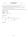
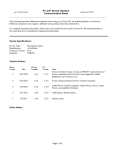
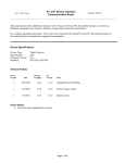
IP Link® Device Interface Communication Sheet ilt_13_2105_7.pke Revision: 10/17/2013 This document provides additional assistance with wiring your Extron IP Link enabled product to your device. Different components may require a different wiring scheme than those listed below. For complete operating instructions, refer to the user's manual for the specific Extron IP Link enabled product or the controlled device manufacturer supplied documentation. Device Specifications: Device Type: Manufacturer: Firmware Version: Model(s): Lighting Control iLight N/A Source Controller Version History: Driver Version Date IP Link Compiler GC Version Notes 7 10/8/2013 1.6.0 3.5.1 Extron Certified Version. Made changes to the wiring diagram and status. 6 4/2/2013 1.5.1 3.3.2 Fixed Channel Level Status. Accounted for the response echoing back the query. 5 02/10/2011 1.4.0 3.0.4 Fixed command strings for Scene Recall/Save. 4 05/11/2010 1.4.0 3.0.3 Added Scene Status. Changed Scene Select and Recall functions to drop down menus. 3 01/26/2010 1.4.0 3.0.2 Custom version. Added Query Enable to allow user to query the device or not. Changed Port Type from RS-485 to RS-232. 2 12/30/2009 1.4.0 3.0.2 Updated for TLP compatibility. 1 02/25/2005 1.0.9.3 N/A Initial version. Page 1 of 5 ilt_13_2105_7.pke IP Link® Device Interface Communication Sheet Revision: 10/17/2013 Driver Notes: The ‘Save Scene’ function can save to the ‘Current Scene’ or to any scene (1 – 99). Once the command is completed, it will return to ‘Select’. ‘Scene Recall’ shows the current scene. ‘Current Scene’ will not work if ‘Scene Recall’ is set to ‘Off’. Default Area and Channel is set to 1 and the default fade time is set to 0. All functions require certain options to be selected before they are executed: Function Channel Channel Level X Channel Level (Step) X Fade Stop X Scene Recall Scene Save Page 2 of 5 Area X X X X X Fade X X IP Link® Device Interface Communication Sheet ilt_13_2105_7.pke Revision: 10/17/2013 Control Commands & States: Area Select 1 – 99 Channel Level 0 to 100 in steps of 1 Channel Level (Step) Up Down Channel Select ALL 1 – 99 Fade Stop Fade Time 0 – 99 Scene Recall Off 1 - 99 Scene Save Current Scene 1 – 99 Status Available: Channel Level* 0 to 100 in steps of 1 Connection Status Connected Disconnected Scene Recall Off 1 - 99 *Channel Level status is unavailable when Channel Select is set to ALL. MLC60 Series Supported Commands: User-defined commands are recommended to be used for control with the MLC60 series. Page 3 of 5 ilt_13_2105_7.pke IP Link® Device Interface Communication Sheet Revision: 10/17/2013 Cable and Adapter Requirements: A custom cable may be required. There are three methods of connecting the IP Link device to the source controller: RS485, RS232-to-RS485 adapter, RS232-to-iCAN. The RS485 method is the most straight-forward and is the one presented in the wiring diagram on the next page. Any commercially available RS232-RS485 adapter can be used in lieu of direct RS485. The required cabling will vary depending on brand and model of adapter used. Consult the IP Link device and the adapter manuals for pinouts. The last method, RS232-to-iCAN, requires an iLight serial node. A M/F straight modem cable (Extron Electronics P/N 26-433-01) and a F/F 9-pin DSUB gender changer (Extron Electronics P/N 10-438-10) are required between the IP Link device and the iLight serial node for this method. This is the only connection method that can be used with source controllers lacking RS485 ports. If either method that utilizes RS232 is chosen, the user must change the port type to RS232 in the IP Link device’s default web pages. If the IP Link device is reset, the port type will change back to RS485. Consult the user’s manual for your IP Link device for more information. Serial communication: Port Type: RS-485 Baud Rate: 9600 Data Bits: 8 Parity: None Stop Bits: 1 Flow Control: None Pin Assignments Diagram: Page 4 of 5 ilt_13_2105_7.pke IP Link® Device Interface Communication Sheet General Notes: Page 5 of 5 Revision: 10/17/2013