1
RDMODGSM-TV
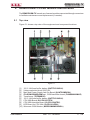
3.2 Bottom view
Figure 3.2
[1] MAINS IN
VDE mains power supply connector
[2] 24 VDC
Jacks (red - black) for 24V DC output.
[3] GSM ANTENNA N-type connector for antenna connection.
[4] AUDIO ADJ.
Trimmer for audio input level adjustment.
[5] AUDIO IN
Audio input female jack connector.
[6] EXT. TELEMETRY
N.C. (Provided for future expansion).
[7] AMPLIFIER TELEMETRY
N.C. (Provided for future expansion).
[8] PTX-LCD REMOTE
DB15 connector for telemetry connection to SAU/SAV and STU/STV series.
[9] RS485
DB9 connector for RS485 communication.
[10] RS232
DB9 connector for communication interface to external devices.
[11] I2C
DB9 connector for I2C communication.
3.3 Connector pinouts
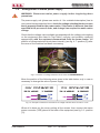
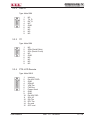
3.3.1 RS485
Type: DB9 female
1
2
3
4
5
6
7
8
9
14 / 18
N.C. (internally not connected)
B
A
N.C. (internally not connected)
GND
N.C. (internally not connected)
N.C. (internally not connected)
N.C. (internally not connected)
N.C. (internally not connected)
Rev. 1.0 - 18/04/08
User Manual