1
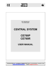
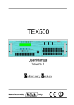
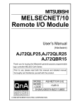
/TLC
Additional Manual for
TEX-LCD series
and TEX-LIGHT series
Manufactured by
Italy
File Name:
03_TLC_ING_1.0.indd
Version:
1.0
Date:
01/02/2008
Revision History
Date
Version
01/02/2008 1.0
Reason
Prima Edizione
Editor
J. H. Berti
/TLC - Additional Manual
Version 1.0
© Copyright 2008
R.V.R.
Elettronica SpA
Via del Fonditore 2/2c - 40138 - Bologna (Italia)
Phone: +39 051 6010506
Fax: +39 051 6011104
Email:
[email protected]
www.rvr.it
Web:
All rights reserved
Printed and bound in Italy. No part of this manual may be reproduced,
memorized or transmitted in any form or by any means, electronic
or mechanic, including photocopying, recording or by any information storage and retrieval system, without written permission of the
copyright owner.
/TLC
Table of Content
1.
1.1
1.2
1.3
2.
3.
3.1
3.2
General Description Remote alarm monitoring
Telemetry
Remote control
Remote Alarm Reporting Configuration
TEX-LCD/TLC External Description
Rear Panel TEX-LCD (2 HE)
Rear Panel TEX-LCD (3 HE)
User Manual
Rev. 1.0 - 01/02/08
1
1
3
3
5
9
9
11
/TLC
This page was intentionally left blank
ii
Rev. 1.0 - 01/02/08
User Manual
/TLC
1. General Description
The telemetry option, whether internal or external, supports connectivity to the
whole range of units of RVR’s TEX-LCD and TEX-LIGHT family of products.
This section describes the features introduced with /TLC version (option with
external telemetry without modem) and the necessary steps for their proper
configuration.
The telemetry option supports:
•
Remote alarm reporting by sending SMS messages through a GSM modem
or through a PSTN modem (dial-up) by sending an alarm message string to a
connected PC.
•
Telemetry, with all equipment parameters sent to the “TELECON” software
through an RS232 connection.
•
Remote controlling through an RS232 connection to the “TELECON” software
or through certain predetermined SMS messages if an external GSM modem
is connected.
•
Telemetry on internet across 10Base-T LAN/Ethernet network through TCP-IP
-INT/TEX external interface connection.
1.1 Remote alarm monitoring
•
Alarm generation parameters are listed below:
•
Exciter output power (forward power good “PgD”);
•
Reflected power at the exciter (reflected power good “PgR”);
•
Temperature state (OVER TEMPERATURE);
•
Audio Signal Level;
•
Mains voltage state (present or missing).
Factory default settings are as follows:
ALARM
Forward Power (Fwd Pwr)
Reflected Power (Rfl Pwr)
Audio
Over Temperature
Mains Power (Mains)
TIME
25 Sec.
25 Sec.
325 Sec.
25 Sec.
25 Sec.
THRESHOLD
Power Good (PgD)
Power Good (PgR)
20 kHz
72°C
Table 1.1
An inhibit time (start time) after power-on is provided to ensure false alarm
prevention. When this inhibit time times out, the thresholds of alarm generation
parameters are checked and remote alarms are sent if needed.
Alarm generation technique is outlined in the figure below; remote alarm delay, i.e.
the amount of time the system waits before issuing a remote alarm after an alarm
condition occurs is indicated in table 1.1. When appropriate, a new line is added
to the alarm log stored in /TLC, up to six lines maximum.
User Manual
Rev. 1.0- 01/02/08
/ 12
/TLC
Figure 1.1
The alarm log may be reviewed using the “TELECON” software or through SMS
(see relevant section).
WARNING: The mains alarm is triggered from the battery charger board; as a result,
this board is required even when no batteries are installed. In the configuration
without batteries, no alarm is generated; instead, an SMS message indicating a
normal condition is sent upon next start-up.
When any one of the parameters listed above changes state, a text message with
the following information is sent via modem (if fitted):
•
Station Name.
•
Station ID.
•
State of measurements.
EX1.
TLC ID:01-Station NameFwd Power OKRFL Power OKOver Temp OKAudio
OKMains
OK-
EX2.
/ 12
TLC ID:01-Station NameAlarm Fwd PowerRFL Power OKOver Temp OKAlarm Audio Alarm Mains -
Rev. 1.0 - 01/02/08
User Manual
/TLC
1.2 Telemetry
Equipment telemetry consists in the remote monitoring of all operating parameters
and can only be achieved through serial cable or modem connection to the
“TELECON” software.
1.3 Remote control
When the exciter is connected to the internal telemetry unit, it can be controlled
from a PC.
Fig.1.2: Example of Modem-to-PC connection
The “TELECON” software establishes connection with the station and enables the
following remote operations: alarm reset, transmitter power on/power off, power
supply reduction, dummy load testing, etc., data evaluation to locate possible
faults, identification of parts required for repair.
An alternative remote controlling option uses SMS messaging through a common
GSM phone (if connected with an external GSM modem), in which case the
equipment will respond as indicated in table 1.2.
Before querying the system using SMS messages, establish a connection using
the “TELECON” software and set the provider service centre number and the
telephone numbers authorised to send these commands to the devices.
User Manual
Rev. 1.0- 01/02/08
/ 12
/TLC
The internal and external telemetry options support the following commands:
Command
INFO
INFO1
TXON
TXOFF
ALARM
RESET
RESMOD
Response
Station: “station name”ID: “station identifier”FWD: “absolute value”RFL: “absolute value”Temp: “absolute value”TX On (or TX Off)Alarm Present / Alarm Absent
Description
Transmitter status
information
Forces the transmission of
an alarm SMS msg
Alarm SMS message
Station: “station name”ID: “station identifier”TX is On Station: “station name”ID: “station identifier”TX is Off Station: “station name”ID: “station identifier”Alarm: “Alarm log”
Station: “station name”ID: “station identifier”ALARM RESET OK-
Transmitter power-on
Transmitter power-off
Alarm log
Clear Alarm Log
Resets and re-initialises
modem
-- none --
Table 1.2
/ 12
Note: Response time to SMS commands may vary with different GSM network
providers; as a general rule, response time should not exceed 7-10 minutes
maximum.
Rev. 1.0 - 01/02/08
User Manual
/TLC
2. Remote Alarm Reporting Configuration
Firstly, you will have to set certain parameters in the (internal or external) telemetry
option using the “TELECON” software. Connect the PC serial port COM to the
RS232 connector on the rear panel of the /TLC option using a standard Male DB9
- Female DB9 serial cable.
Fig.2.3: Example of connection between TEX-LCD unit with /TLC option and PC
When using the “TELECON” software for the first time, select the station and then
enter:
•
COM port used,
•
Baud rate (set to 9600),
•
type of connection (set to direct, via cable).
When you have entered the correct data, click the “Start” button to confirm and
the “TELECON” main screen appears, as shown in the figure:
User Manual
Rev. 1.0- 01/02/08
/ 12
/TLC
Use this screen to change Start time. To edit this parameter, click the “TStart” box
with the left mouse button (default setting is 300sec., the equivalent of 5 min.); this
opens a window where you can change the setting. Press Enter to confirm.
Double click the green label in the top left corner of the TELECON screen and
select “Eeprom” (as shown in the figure below).
In the open menu, press this key to view station parameters.
/ 12
•
Select the “General” data category and set the 5 parameters:
•
STATION ID: Station identifier;
•
STATION NAME: (max 18 characters);
Rev. 1.0 - 01/02/08
User Manual
/TLC
•
DIAL STRING: required setting for a GSM modem is ATDT;
•
NUMBER OF RETRY: number of alarm transmission repetitions;
•
SERVICE CENTER NUMBER: number of GSM provider service centre for
SMS transmission and reception; place country code before number.
Example with Italian service providers:
TIM:
+393359609600
VODAFONE:
+393492000200
WIND:
+393205858500
Now select the “Telephone” data category and set the following:
User Manual
Rev. 1.0- 01/02/08
/ 12
/TLC
•
PHONE NUMBER: GSM phone numbers recognised by the station to which
you want the alarms sent;
•
SMS: select “YES” to enable transmission of SMS commands to system;
•
ACS: select “YES” to enable SMS reception.
Note: For correct transmission, place country code (+XX) before set numbers
(Use +39 for Italy).
When all parameters are set, press this key and the internal or external Telemetry
option will store the information.
When finished, click “Exit” to exit the remote station programming window.
Back into “TELECON” standard interface, click the “General” measurement
selection button to set thresholds and operation times for the various alarms
according to the principles outlined in Section “Alarm Management”.
/ 12
Note: When setting alarm thresholds, allow a margin of some percent points with
respect to normal operation parameters.
Rev. 1.0 - 01/02/08
User Manual
/TLC
3. TEX-LCD/TLC External Description
This section describes the components found on the rear panel of the internal
telemetry option \TLC.
3.1 Rear Panel TEX-LCD (2 HE)
figure 3.1
[1]
[2]
[3]
[4]
[5]
[6]
PLUG
VENTOLA
R.F. OUTPUT 24 VDC IN- 24 VDC IN- INTERLOCK OUT
[7] FWD EXT. AGC
[8] RFL EXT. AGC
[9] REMOTE
[10]GSM ANT
[11]PHASE ADJ
[12]MODE/MPX IMP
[13]SCA/RDS
[14]MPX
[15]MPX ADJ
[16]SCA/RDS ADJ
[17]RIGHT ADJ
[18]RIGHT
[19]FUSE BLOCK
[20]R.F. TEST
[21]MODEM
User Manual
VDE plug for mains voltage.
Fan for the forced ventilation of the exciter.
RF output connector, N-type, 50 Ω
External 24Vdc supply input. Negative (black).
External 24Vdc supply input. Positive (red).
Interlock output BNC connector: when the transmitter goes
into stand-by mode, the (normally floating) central conductor
is switched to ground.
Trimmer to set output power limitation according to FWD
fold input.
Trimmer to set output power limitation according to RFL fold
input.
DB15 telemetry connector.
TEX-LCD: Not present.
TEX-LCD/TLM: SMA connector for GSM.
TEX-LCD/TLC: Not present.
Pilot tone phase trimmer.
Dip-switch used to select transmission mode (STEREO or
MONO) and MPX input impedance (50 Ω or 10 kΩ).
BNC connector for unbalanced SCA1/RDS input.
Unbalanced MPX input BNC connector.
Trimmer for MPX input level adjustment.
Trimmer for SCA1/RDS input level adjustment.
Trimmer di regolazione dei livelli dell’ingresso destro
Right audio channel input XLR connector.
Fuse carrier.Use a screwdriver to access the fuse. Contains
the general protection fuse.
Output with level 13 dBm lower than output power level,
suitable for modulation monitoring. Not suitable for
spectrum analysis.
TEX-LCD: Not present
TEX-LCD/TLM: DB9 Connettor for GSM modem
connection.
TEX-LCD/TLC: Power supply output for external modem or
TCP/IP-INT-TEX interface.
Rev. 1.0- 01/02/08
/ 12
/TLC
[22]I2C BUS
[23]RS232
[24]SERVICE
[25]EXT REF 10MHz
[26]PREEMPHASIS
[27]19 kHz PILOT OUT
[28]SCA2
[29]SCA2 ADJ
[30]LEFT-MONO ADJ
[31]LEFT-MONO
[32]IMPEDANCE
10 / 12
TEX-LCD: Non present
TEX-LCD/TLM o /TLC: DB9 connector for I2C bus network.
Usually not used, or used for special operations depends on
customer requirements.
TEX-LCD: Not present.
TEX-LCD/TLM o /TLC: DB9 connector for serial, direct or
modem communications.
DB9 connector for factory setting.
BNC connector for synchronism signal for external devices.
Preemphasis dip-switch, provides two settings: 50 or 75
μs. Preemphasis affects the right and left inputs in stereo
mode and the mono input. MPX inputs are not affected by
preemphasis setting.
Tone output BNC connector, may be used to synchronise
external devices such as RDS coders.
BNC connector for unbalanced SCA2 input.
Trimmer for SCA2 input level adjustment.
Trimmer di regolazione dei livelli dell’ingresso sinistro-mono
Left-mono audio channel input XLR connector.
Dip-switch used to select balanced audio input impedance
(600 Ω or 10 kΩ).
Rev. 1.0 - 01/02/08
User Manual
/TLC
3.2 Rear Panel TEX-LCD (3 HE)
[1] R.F. TEST [2] GSM SLOT-IN
[3] GSM ANT
[4]
[5]
[6]
[7]
AIR FLOW
10MHz
PHASE ADJ
19 kHz PILOT OUT [8] PREEMPHASIS
[9] MODE/MPX IMP
[10]SCA2
[11]SCA1
[12]MPX
[13]SCA2 ADJ
[14]MPX ADJ
[15]SCA1 ADJ
[16]RIGHT ADJ
[17]RIGHT
[18]IMPEDANCE
[19]MAINS
[20] FUSE 1 [21]R.F. OUTPUT [22]INTERLOCK OUT
[23]SERVICE
[24]INTERLOCK IN
[25]MODEM
User Manual
Figura 6.2
Output with level -60 dB lower than output power level,
suitable for modulation monitoring. Not suitable for spectrum
analysis.
Reserved for future implementations.
TEX-LCD: Not present
TEX-LCD/TLM: SMA connector for GSM
TEX-LCD/TLC: Not present
Air grille.
Reserved for future implementations.
Pilot tone phase trimmer.
Tone output BNC connector, may be used to synchronise
external devices such as RDS coders.
Preemphasis dip-switch, provides two settings: 50 or 75
μs. Preemphasis affects the right and left inputs in stereo
mode and the mono input. MPX inputs are not affected by
preemphasis setting.
Dip-switch used to select transmission mode (STEREO or
MONO) and MPX input impedance (50 Ω or 10 kΩ).
BNC connector for SCA2 input.
BNC connector for SCA1 input.
Unbalanced MPX input BNC connector.
Trimmer for SCA2 input level adjustment.
Trimmer for MPX input level adjustment.
Trimmer for SCA1 input level adjustment.
Trimmer for right input level adjustment.
Right audio channel input XLR connector.
Dip-switch used to select balanced audio input impedance
(600 Ω or 10 kΩ).
Connectors for 115-230 V 50-60 Hz mains power supply.
Mains power supply fuse
RF output connector, N-type for TEX500-LCD and 7/16” for
TEX1000LIGHT, TEX1000-LCD and TEX1300-LCD.
Interlock output BNC connector: when the transmitter goes
into stand-by mode, the (normally floating) central conductor
is switched to ground.
DB9 connector for factory setting.
Interlock input BNC connector: the exciter is forced in standby mode when the inner conductor is grounded.
TEX-LCD: Not present
TEX-LCD/TLM: DB9 Connettor for GSM modem connection.
TEX-LCD/TLC: Power supply output for external modem or
TCP/IP-INT-TEX interface.
Rev. 1.0- 01/02/08
11 / 12
/TLC
[26]FWD EXT. AGC
[27]RFL EXT. AGC
[28]REMOTE
[29]RS232
[30]SERVICE VOLTAGE SEL.
[31]I2C BUS
[32]SERVICE FUSE
[33]LEFT ADJ
[34]LEFT
[35] FUSE 2 12 / 12
Trimmer to set output power limitation according to FWD
fold input.
Trimmer to set output power limitation according to RFL fold
input.
DB15 telemetry connector.
TEX-LCD: Not present
TEX-LCD/TLM o /TLC: DB9 connector for serial, direct or
modem communications.
115-230V mains voltage selector.
TEX-LCD: Non present
TEX-LCD/TLM o /TLC: DB9 connector for I2C bus network.
Usually not used, or used for special operations depends on
customer requirements.
Service fuse.
Trimmer for left input level adjustment.
Left audio channel input XLR connector.
Mains power supply fuse.
Rev. 1.0 - 01/02/08
User Manual