1
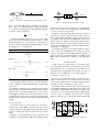
2015 IEEE International Parallel and Distributed Processing Symposium Workshops
Real-Time Multiprocessor Architecture for Sharing Stream Processing Accelerators
Berend H.J. Dekens∗
Marco J.G. Bekooij∗‡
∗
‡
Department of EEMCS
University of Twente
Enschede, The Netherlands
NXP Semiconductors
Eindhoven, The Netherlands
However, sharing of accelerators is challenging under realtime constraints as a system implementation is required which
can be captured in a temporal analysis model. With such
an analysis model the minimum granularity at which blocks
of data, i.e. the block size, must be multiplexed over the
accelerators can be computed given the minimum throughput
requirement of a stream of data of an application. Computation of the minimum granularity is complicated by the fact
that a larger granularity amortizes accelerator reconfiguration
overhead and thereby increases the throughput of one stream.
However, this results also in a longer occupation of the
accelerators and thereby reduces the throughput of other
streams that share the same accelerator. As such, there is
a mutual dependency between the minimum block sizes
for different streams. Another complicating factor is that
intuitively a smaller block size should result in a smaller
buffer capacity but this is not generally the case because the
required buffer capacities are a non-monotonic function in
the block sizes. As a result the total required memory size
for buffering is a non-monotonic function in the block size
as well.
In this paper we present an approach for sharing accelerators under real-time constraints in a multiprocessor
architecture for stream processing applications. Sharing of
stream processing accelerators is enabled by multiplexing
data streams using so-called entry- and exit-gateways. These
gateway pairs check for sufficient input data and output space
at respectively the input and output of a chain of accelerators
such that the minimum throughput can be derived using a
Cyclo-Static Data Flow (CSDF) model [1]. An abstraction
of this CSDF model is created in the form of a single actor
Synchronous Data Flow (SDF) model. This SDF model
enables the derivation of an Integer Linear Program (ILP)
for the computation of the minimum granularity at which
blocks of data from the streams must be multiplexed over
shared accelerators.
The achieved reduction in hardware cost has been evaluated
by creating a multiprocessor system with shared accelerators
that is implemented on a Virtex 6 FPGA. This system has
been evaluated using a real-time Phase Alternating Line
(PAL) stereo audio decoder application.
The outline of this paper is as follows. In the next
Abstract—Stream processing accelerators are often applied
in MPSoCs for software defined radios. Sharing of these accelerators between different streams could improve their utilization
and reduce thereby the hardware cost but is challenging under
real-time constraints.
In this paper we introduce entry- and exit-gateways that are
responsible for multiplexing blocks of data over accelerators
under real-time constraints. These gateways check for the
availability of sufficient data and space and thereby enable the
derivation of a dataflow model of the application. The dataflow
model is used to verify the worst-case temporal behavior based
on the sizes of the blocks of data used for multiplexing. We
demonstrate that required buffer capacities are non-monotone
in the block size. Therefore, an ILP is presented to compute
minimum block sizes and sufficient buffer capacities.
The benefits of sharing accelerators are demonstrated using
a multi-core system that is implemented on a Virtex 6 FPGA.
A stereo audio stream from a PAL video signal is demodulated
in this system in real-time where two accelerators are shared
within and between two streams. In this system sharing reduces
the number of accelerators by 75% and reduced the number
of logic cells with 63%.
Keywords-real-time applications; stream processing accelerators; dataflow; accelerator sharing; multiprocessing systems
I. I NTRODUCTION
Nowadays programmable signal processors are applied in
Software Defined Radios (SDRs). A hardware cost reduction
can be achieved by specialization of the instruction set of
these Digital Signal Processors (DSPs). However, the design
effort and associated cost to create such processors and their
accompanying compilation tool-chains can be significant.
Stream processing hardware accelerators can be an attractive alternative compared to the use of specialized DSPs.
These accelerators can improve the performance and powerefficiency at the cost of reduced flexibility.
Sharing of accelerators between data streams could improve their utilization and reduce thereby hardware costs.
Accelerators can be shared by different streams within one
application or by data streams from different radios that
are executed simultaneously on the multiprocessor system.
This work is supported by the SenSafety project in the Dutch COMMIT
program (commit-nl.nl).
/15 $31.00 © 2015 IEEE
DOI 10.1109/IPDPSW.2015.147
Gerard J.M. Smit∗
81
section we will describe related work. The basic idea behind
our approach is described in Section III. In Section IV
we describe our architecture with gateways in detail. The
derivation of the temporal analysis models in the form of
a CSDF and the more abstract SDF model are described in
Section V. The evaluation of our system in terms of hardware
costs and utilization of the accelerators using a real-time PAL
stereo audio decoder application is described in Section VI.
The conclusion is stated in the last section.
P T2
P T3
G2
Acc2
G3
P T4
G1
P T1
dual-ring interconnect
P T0
Figure 1.
II. R ELATED W ORK
G0
Acc0
Acc1
Example architecture overview with all types of tiles
to provide real-time guarantees. Accelerators stream data
through FIFO channels, hiding all network aspects. Like our
design, a special bus is used to configure accelerators while
a streaming network handles all data. Processors in [9] are
not connected to the data streaming interconnect, unlike our
approach, making it impossible to integrate them in a stream
processing application directly. Multiplexing of data streams
is supported where state is retained within the accelerators,
limiting the number of multiplexed streams per accelerator.
Eclipse [10] employs a shell to integrate stream processing
accelerators, an approach similar to the network [11] used
in our design. The use of the C-FIFO [12] algorithm in
a hardware shell results in larger hardware costs than our
credit-based hardware flow-control support in our network. A
shell around every accelerator manages arbitration between
multiplexing data streams. Our implementation only requires
logic for arbitration in the gateways instead of in every
accelerator. There is no temporal analysis model presented
and performance is measured instead within a simulator.
Our approach of using a network to stream data between
accelerators and a dedicated bus to save and restore accelerator state is similar to [13]. However, the use of a switch
to implement point-to-point connections results in higher
hardware costs compared to the ring-based interconnect
of [14], [11] which is used in this paper. The interconnect
from [13] provides real-time guarantees but lacks support to
share accelerators.
Hardware accelerators can be integrated into systems
as Instruction-Set Extensions (ISEs), by means of Remote
Procedure Calls (RPCs) or by making use of Direct Memory
Access (DMAs). We additionally will describe architectures
designed for accelerator integration which employ DMAs.
ISEs allow fine grained interaction with application specific
accelerator hardware due to a low communication latency
and usually without synchronization overhead. This type
of accelerator integration is applied in (general purpose)
processors [2], [3], [4] and proposed as a way to save power
by integrating so-called conservation cores [5]. A potential
drawback is that the processor is usually stalled until the
accelerator returns the result which limits the maximum
achievable performance gain. An additional drawback is
that accelerators usually belong to a single core, preventing
sharing between cores to improve utilization.
The use of RPCs [6] allows a less tight integration
between processors and accelerators. For communication
with accelerators synchronization needs to be added which
results in some overhead. While concurrent processing of
processor and accelerator is possible in theory, in practice it
is difficult as results from the accelerator are often required
for application progression. Additionally, it is not trivial to
keep the processor occupied during the exact duration of the
RPC call to maximize performance gains [7].
An architecture which makes use of DMAs for the
communication with accelerators is described in [8] and
allows concurrent processing of data streams by processors
and accelerators. In [8] they also describe a CSDF model
for the derivation of the minimum throughput for the case
that accelerators are shared by multiple streams. What is
missing in [8] is the check for space at the output of a chain
of accelerators, before processing of a block of data begins.
Without this check, no correct CSDF model can be derived.
Furthermore, determining an appropriate block size for every
multiplexed stream given a throughput constraint has not
been addressed in [8]. We will introduce a single actor SDF
model for the derivation of the minimum block size which
takes both the overhead caused by the flushing the data out
of a pipeline of accelerators and the time needed for saving
the state of the accelerators into account.
PROPHID [9] is an architecture which uses a crossbar with
a pre-calculated Time Division Multiplex (TDM) schema
III. BASIC I DEA
In this section we present a high level overview of our
architecture and the relation with the dataflow models used
for the derivation of the minimum block size.
An overview of our hardware architecture is shown in
Figure 1. In this architecture an entry-gateway hardware
block is responsible for scheduling blocks of data from
different streams over a chain of accelerators. Streaming of
a block of data is only allowed if:
1) the exit-gateway has indicated that all data in the chain
of accelerators belonging to the previous block has
been processed so a context switch can be performed,
and:
2) enough space is available at the output buffer such
that a consuming task can receive the next block of
data without having to stall for additional space in this
buffer
82
A CSDF model suitable for temporal analysis can be
created for this hardware, which is shown simplified for
clarity in Figure 2. We show that one CSDF model per stream
can be created despite that accelerators are shared. This
CSDF model is a conservative abstraction of the hardware
implementation. We will show that the minimum throughput
can be derived using this model.
We will use the symbol to indicate that the CSDF model
is a conservative abstraction of the hardware. As such, the
hardware is a temporal refinement of this model, according to
the-earlier-the-better [15], [16] refinement theory. This theory
is applicable if the application is functional deterministic and
for each component it holds that:
they are enabled. Actors are enabled if sufficient tokens
are available in their input queues. During the construction
of this schedule we use worst-case firing durations of the
actors. These firing durations are equal to the maximum
durations between arrival of the data enabling a task such that
it becomes eligible for execution and the actual production
of data by this task. Tasks can be executed by accelerators
or by processors.
The block size determines the number of samples to be
processed by the accelerators before a block of another stream
can be processed. To derive the block size using the dataflow
model we cannot make use of Maximum Cycle Mean (MCM)
analysis techniques [17] as these analysis techniques require
that expansion into an Homogeneous Synchronous Data Flow
(HSDF) graph is possible [1]. However, an HSDF graph with
a fixed topology cannot be derived as the block size remains a
variable parameter in the CSDF model. Instead of computing
the MCM we construct a schedule that is parameterized in
the block size.
We will show that a more compact parameterized SDF
model can be created from this CSDF model with a minimum
loss of accuracy. As such, the CSDF model is a refinement of
the SDF model, as is indicated in Figure 2. Due to transitivity
of the relation we can conclude that also the hardware is
a refinement of this SDF model. We will show that this SDF
model is suitable for the derivation of the minimum block
size such that the throughput constraint of the application is
satisfied despite overhead of saving the state and flushing
data out of the FIFO buffers between the accelerators.
∀i, a(i) ≤ â(i) ⇒ ∀j, b(j) ≤ b̂(j)
This equation states that an earlier arrival of the i-th input
token at time a(i) in the refined model compared to the arrival
of the corresponding token in the abstraction at â(i) should
not result in a later production of the token by the refined
model at b(j) compared to production of the corresponding
j-th token by the abstraction at b̂(j). This equation can
be generalized for components with multiple inputs and
outputs. If the equation holds we say that component C
refines component C and this is formalized as C C .
A component can be an actor, its corresponding task or
subgraphs of actors or tasks. If the refinement relation holds
per component than it holds also for a complete graph of
components. This means that the worst-case throughput and
latency of the refined graphs is always better than the model
being refined, i.e. the model obtained by abstraction. As such
temporal guarantees concerning maximum token arrival times
derived for the abstract model are always valid for the refined
model and this also holds for subgraphs of these models. As
a result, it is sufficient to show that a schedule of the abstract
model exists that satisfies the temporal requirements.
We can therefore determine the minimum throughput by
creating an admissible schedule for the CSDF graph at design
time. In an admissible schedule actors do not fire before
ρ
P0
ρ
v P0
ρ
v P0
v G0
G0
vA0,1
SDF
ρ
P0
A0,1
ρ
A0
v A0
CSDF
ρ
C0
IV. P ROPOSED A RCHITECTURE
In this section we will introduce the heterogeneous
Multiple Processor System on Chip (MPSoC) architecture
for real-time stream processing applications [11] which
was extended with support for sharing stream processing
accelerators. It consists of a number of interconnected “tiles”
which contain processing elements.
In Figure 1 an overview of our architecture is presented.
The “tiles” come in four types: the “Processor Tile” (PT),
which contains a processor and some peripherals, the “Accelerator Tile” (Acc) which contains a configurable stream
accelerator, the “entry-gateway” tile (G0/G2) and the “exitgateway” tile (G1/G3). Each pair of entry- and exit-gateways
handles multiplexing of data streams over a specific set of
accelerator tiles. As reconfigurating or replacing state within
the accelerators while data is still being processed in those
accelerators would result in corrupt data, the entry- and exitgateway work together to ensure that the pipeline is idle
before another data stream is multiplexed. Such a pair of
gateways is indicated by the dashed boxes in Figure 1. As
interconnect we use the low-cost dual communication ring
network from [11].
We will present the different types of tiles in more detail
in the following sections.
v C0
ρ
A1
ρ
v A1
v G1
G1
ρ
C0
v C0
P0
Entry
Gateway
P1
A0
A1
C0
Exit
Gateway
C1
Reality
Figure 2.
Basic idea for sharing accelerators
83
dual-ring interconnect
dual-ring interconnect
dual-ring interconnect
dual-ring interconnect
Timer
IRQ
Ring
FIFO
IRQ
Timer
C-FIFO
Ring
FIFO
D
A+D
DMA
C-FIFO
Memory
Memory
μBlaze
PLB Bus
LMB
LMB
PLB Bus
Accelerator
DMA
μBlaze
BRAM
BRAM
Processor Tile
Accelerator
Tile
acc. configuration bus
(a) Processor Tile
Figure 3.
Exit
Entry-gateway
acc. cfg. bus
(b) Accelerator Tile
(a) Entry-gateway
Overview of Processor and Accelerator tiles
Figure 4.
A. Processor Tile
-gateway
cfg
(b) Exit-gateway
Overview of both gateway types
receive one data stream from an accelerator tile and send
one data stream to an accelerator tile to minimize hardware
costs.
Figure 3a shows an overview of a processor tile. Every tile
contains a RISC Microblaze processor and some peripherals
like a timer for interrupts, a small local memory for a bootloader and a small data scratch pad memory. Every processor
is equipped with an instruction and data cache which is
sufficiently large to cache program code of tasks running
on the processor. Tasks are governed by a real-time budget
scheduler [18] from a POSIX compliant kernel with multithreading support which was developed for this system.
Every processing tile is connected to a tree-shaped interconnect providing fair access to external memory, which
is for the case study presented in this paper unused and
as such is omitted in the rest of this paper. It also has a
connection to a dual-ring interconnect providing streaming
tile-to-tile communication for data streams. In order to keep
hardware costs low, the inter-tile interconnect only supports
posted writes: a write completes for a producer when the
interconnect accepts, it does not wait until the write actually
arrives at its destination memory. The interconnect provides
lossless communication where guaranteed acceptance at every
tile is required to prevent loss of data which removes the need
for hardware flow control for communication with memories.
Tiles can only write data to a remote memory; when data
from a remote tile is needed, both tiles need to work together
to exchange data.
Processor tiles support two types of data streams: software
FIFO communication, using the C-FIFO [12] algorithm,
which allows an arbitrary number of simultaneous streams
between processing tiles or hardware FIFO communication
which is used to communicate directly with accelerator tiles.
To support hardware FIFO communication we use a credit
based flow control mechanism. This is implemented with a
second ring for the communication of credits in the opposite
direction as the data [11]. Currently it is only possible to
B. Accelerator Tile
Accelerator tiles, as depicted in Figure 3b, consist of a
coarsely programmable accelerator and a streaming I/O port
to the inter-tile dual-ring interconnect. The network interface
handles the transition from address based communication to
streaming data [11].
As such, the accelerators have no notion of other aspects
of the system: they consume an incoming data stream from
the Network Interface (NI) and produce a data stream which
is returned to the NI. Accelerators can stall the incoming
or outgoing stream of data tokens if they run out of data or
space. To this end, the NIs for accelerators use a credit-based
flow control algorithm.
Each accelerator is connected to a bus to load and save
its state and configuration. This is used to provide context
switches when different data streams are multiplexed.
Accelerators are chained together at run-time by a description written by a programmer which describes the flow of data
between tiles. A support library abstracts the implementation
details and allows a programmer to simply connect blocks
of functionality in a programming language like C.
C. Gateways
Entry-gateways are based on processor tiles and as such
contain the same components plus some components needed
for managing accelerators and multiplexing data streams, as
is shown in Figure 4a. Configuration and state of accelerators
are loaded and saved by means of a configuration bus which
is connected to all managed accelerators. Configuration and
state are stored in the local memory of the entry-gateway
for every multiplexed stream. To prevent the speed of the
84
B. CSDF Model
processor becoming a bottleneck in the data path, data is
forwarded to the accelerators by a small DMA.
The entry-gateways handle streams using a Round-Robin
(RR) scheduling policy. The use of RR allows to multiplex
unrelated streams for multiple applications that are being
executed simultaneously on the MPSoC.
Data streams arriving at the entry-gateway use software
FIFOs store their data in the dual ported C-FIFO memory.
The DMA controller copies data for the currently active
stream from this local FIFO memory to an accelerator using
hardware credit-based flow control. Produced data by the
last accelerator in the chain is passed to the exit-gateway,
which converts from hardware to software flow control, to a
processing tile or entry-gateway.
The exit-gateway is an accelerator containing a DMA
converting the hardware flow-controlled data stream to the
address based software flow-controlled FIFO, as is shown in
Figure 4b. When the last sample from a data block passed
through the exit-gateway, the entry-gateway is notified that the
pipeline is idle and another data stream can be multiplexed.
In our approach gateways are used for multiplexing of
data streams over a set of accelerators. For each stream that
is multiplexed over the accelerators a separate CSDF model
is created. A CSDF model for one such stream is shown
in Figure 5. To keep the figure concise we assume, without
loss of generality, that only one accelerator is shared. This
accelerator is modeled with actor vA . The values of α1 and
α2 are two tokens and are equal to the capacity of the buffers
in the network interfaces.
In the CSDF model, the entry-gateway is modeled by actor
vG0 and the exit-gateway is modeled by vG1 . The first phase
of vG0 can not start before vG1 has produced a token on the
edge (vG1 , vG0 ) which indicates that the previous block of
data has been processed. Additionally vC must have produced
ηs tokens to indicate that ηs locations are available in the
input buffer of vC . Furthermore at least ηs tokens have been
produced by actor vP before the first phase of vG0 can start.
Actor vG0 produces ηs tokens, one in each phase. All
phases denote the transfer of a sample to the shared
accelerator vA . Actor vA will consume each token and
produce a token for the exit gateway actor vG1 . After vG1 has
produced ηs tokens for actor vC , with each token modeling
an output sample from the shared accelerator to the consumer,
it produces a token to notify vG0 that the pipeline is idle.
The time that other streams might use the accelerators
before stream s ∈ S can be processed, denoted by s is
a function in the block sizes of all other streams and is
included in the firing duration of the first phase of actor
vG0 . The set S contains all streams multiplexed by an entry/exit-gateway pair over a set of accelerators. The time Rs
required to reconfigure the accelerators for stream s is also
included as well as the time it takes for vG0 to copy a sample,
which is denoted by . As such, the firing duration of ρG0 [0]
becomes:
(1)
ρG0 [0] = s + Rs + V. DATAFLOW M ODEL
In this section the CSDF model of our sharing approach
for accelerators and its SDF abstraction are explained in
detail. We will now first provide a brief introduction into
these models and then present a detailed CSDF model for a
single data stream using a shared accelerator followed by its
abstraction into a SDF model.
A. (C)SDF
An SDF model is a directed graph G = (V, E) with actors
v ∈ V and directed edges e ∈ E. Each edge ei,j describes a
unbounded queue for atomic objects called tokens between
actors vi and vj . The head and tail of each edge is annotated
by quanta which denote the number of tokens an actor will
consume or produce during its firing. Every actor has a firing
duration ρv , which is the duration between the consumption
of input tokens and the production of output tokens. An actor
can fire when its incoming edges have at least the number
of tokens as denoted by their quanta. To prevent concurrent
firing of an actor where this is not desired, a self edge is used
with a single token. Bounded buffers between two actors are
modeled with a forward edge with complementary back edge
containing a number of initial tokens denoting the depth of
the buffer.
CSDF extends SDF by introducing the concept of phases.
Each CSDF actor has by definition an implicit self-edge with
one token. Furthermore, each actor has a cyclic behavior
during which its phases are fired. The firing duration for
every phase p is denoted as ρv [p]. Both firing durations and
quanta are expressed as a list of values with a length equal to
the number of phases of the corresponding actor. To denote a
parametric list of quanta for each phase of a CSDF actor, we
use the notation: z × 1, 0, denoting z phases with quanta
1 followed by one phase of quanta 0.
The durations of all other phases of vG0 are . Similarly, the
time needed to copy a data element by vG1 is denoted by .
Given the CSDF model in Figure 5 we can construct an
execution schedule for the gateways and accelerator that
process a single stream s under the assumption that the
pipeline was initially idle, thus s = 0, as shown in Figure 6.
This schedule is parameterized in ηs and shows that after ηs
firings of all actors a complete block has been processed and
is ready to be consumed by vC . From this schedule we can
conclude that the total processing time of one block of ηs
samples for data stream s is τs time, which is upper bounded
by τ̂s :
τs ≤ τ̂s = Rs + (ηs + 2) · max(, ρA , )
(2)
According to Equation 2, τs consists of the reconfiguration
time plus the time needed to process ηs samples and the time
needed to empty the pipeline of gateways and accelerator(s).
85
ρ
P
vP
ρ
(s+Rs+),(ηs−1)×
b
ηs ,(ηs−1)×0
α0
b
vG0
(ηs−1)×0,ηs ηs ,(ηs−1)×0
ηs×1
1
ηs×1
1,(ηs−1)×0
A
vA
1
α1
ηs× 1
1
ηs×1
α2
ηs×1
vG1
ρ
ηs×1
(ηs−1)×0,1
d
C
vC
d
1
α3
CSDF model of accelerator multiplexing for a data stream s
Figure 5.
τs
vG0
vA
vG1
Rs +
Rs +
(ηs − 1) × ηs × ρ
ηs × ρ
A
Rs +
(ηs − 1) × η s × to the CSDF model is caused by the fact that the SDF actor
will atomically produce all tokens when the actor finishes
while in the CSDF model tokens for vC are produced during
firing of vG1 and will therefore arrive earlier.
This means that the SDF model is more pessimistic than
the CSDF model and as such, according to the-earlier-thebetter refinement, any throughput guarantees from the SDF
model will hold for the CSDF model and hardware as well.
(ηs −
ηs
A
η s × t→
Figure 6. Execution schedule of stream s processing blocks of ηs samples
D. Minimum Throughput Verification
The maximum of the firing durations of the gateways and
the accelerator(s) is taken because the actor with the largest
firing duration in the chain determines the time to process a
sample.
Streams are multiplexed in a RR fashion by the entrygateway. By applying the theory presented in [19] we can
conclude that when a block of data for stream s is queued,
in the worst-case it has to wait s time. This is equal to the
processing duration of a block of data for every other stream
that uses the same accelerator, before the block of stream s
is processed. Therefore s is bounded from above by:
ˆs =
τ̂i
(3)
s ≤ When block sizes are specified by the designer, the firing
duration for actors vs denoting shared accelerators can be
determined using Equation 4. The quanta of vS are equal
to the block size ηs , except for the quanta of the self-edge.
The resulting graph is an SDF graph and the minimum
throughput and the minimum required buffer capacities given
a throughput constraint can be determined using existing
SDF techniques [20].
E. Non-monotone Behavior
When block sizes are not specified by the designer, they
have to be computed for the application. This computation is
difficult as minimum buffer capacities are not monotone in
the block size. We will illustrate this with an example using
the model from Figure 8a.
We can determine for every value of ηs what the minimum required buffer capacities are using an existing SDF
technique [20] to obtain maximum throughput. When we do
this for the model from Figure 8a for ηs = 2 and ηs = 5, we
see that from Figure 8b the small block size requires a larger
buffer capacity than the larger block size. However, when
considering the required buffer capacities needed for ηs = 1
and ηs = 2, the opposite is true. As such, the minimum
buffer capacities are not monotone in the block size and thus
using the smallest possible block size does not result in the
smallest possible buffer capacities in general. A similar issue
occurs for minimum buffer capacities under a throughput
constraint.
i∈S\s
As a result the maximum time γs it takes before a block of
queued samples of stream s is processed, is equal to the sum
of the processing time of one block of data for all streams
sharing that accelerator:
ˆ s + τ̂s =
τ̂i
(4)
γs = i∈S
C. Single SDF Actor model
The detailed CSDF model inside the dashed box in
Figure 5 can be abstracted into a single actor SDF model as
shown in Figure 7. The firing duration of this SDF actor is γ̂s .
There is hardly any loss in accuracy because processing of
the next block cannot start before the previous block has been
processed completely. The only loss in accuracy compared
ρ
P
vP
Figure 7.
b
α0
ηs
ρ
γs
ηs
b
ηs
vS
1
1
ηs
d
α3
d
F. Computing Block Sizes
Our SDF model can be used to create an ILP to compute
minimum block sizes and sufficient buffer capacities. This
ILP is correct for graphs with a topology as shown in Figure 7.
For every stream s in an application a certain minimum
throughput μs is specified, expressed in samples/s, which can
be derived from the throughput constraint of the application.
C
vC
SDF abstraction for a data stream s over an accelerator vs
86
1
1
vA
5
ηs
1
ηs
1
vB
5
αs
(a) SDF model
Figure 8.
ηs
min αs
1
5
2
6
3
7
4
8
t1
5
5
t2
s0 s0 s0 s1
(b) Buffer capacities for various ηs
t3
t4
Stream 0
Stream 1
SDF model showing the buffer size minimization problem
Figure 9.
If we consider the SDF model from Figure 7 and assume
that α0 and α3 are sufficiently large to make the self-edge
on vs critical, the requirement on the minimum throughput
of stream s can be described by:
1
· η s ≥ μs
γs
between the gateways and accelerators in our architecture.
Task v1 and v2 produce and consume data for stream 0. Tasks
v3 and v4 do the same for stream 1.
Dataflow models like SDF define that the moment of
production of a token is the same instant a token arrives at
the consumer. When this FIFO is shared between streams,
for example when streams are multiplexed, tokens from
another stream can influence when produced tokens arrive
at the consumer because of head-of-line blocking. This is
not allowed in SDF and causes that the-earlier-the-better
refinement is not applicable.
Our sharing approach provides mutual exclusivity: when a
stream s wants to use the FIFO it needs to wait for the current
stream to be emptied from the FIFO. When this happens, a
token produced by s will immediately be available at the
FIFO output, satisfying the conditions of the refinement
theory.
(5)
To find the minimum block size for every stream multiplexed over a specific accelerator we have to derive ηi which
satisfies Equation 5 for every stream i ∈ S. The values of
ηi can be computed with the following ILP which is created
by substitution of γs in Equation 5.
Algorithm 1 Find smallest total block sizes
Minimize:
ηs
min
s∈S
Subject to:
∀s ∈ S : ηs − c0 · μs ·
(ηi + 2) ≥ μs · c1
(6)
VI. E VALUATION
i∈S
∀s ∈ S : ηs > 0
(8)
In this section we will describe our real-time stream
processing application used for the evaluation of our system.
The hardware costs of our gateways and accelerators are
presented which demonstrates the benefits in terms of
hardware costs and utilization of our sharing approach.
(9)
A. PAL Stereo Audio Decoder
(7)
Given that:
c0 = max(, ρA , )
c1 =
Rs
Task graph showing shared FIFO sharing
s∈S
In order to demonstrate the sharing of accelerators in a
multi-core heterogeneous system under real-time constraints,
a demonstrator application was constructed which performs
real-time decoding of a PAL stereo audio stream.
In the PAL broadcast standard, video is transmitted using
an Amplitude Modulation (AM) signal at baseband. The
audio signal is offset 6 MHz from the base frequency and
consists of one or two Frequency Modulation (FM) signals
for mono, stereo or bilingual sound. For stereo, the first
channel contains a mix of both the left and the right (L+R)
After finding the smallest block sizes, a standard algorithm
for the computation of the minimum buffer capacities [20]
can be used.
To find the optimal block sizes resulting in the smallest
buffer capacities, a computational intensive branch-and-bound
algorithm can be used. This algorithm has to verify whether
the throughput constraint of every stream is satisfied for every
possible block size and must compute the accompanying
minimum buffer capacities to find the total minimum buffer
capacity.
FIR+LPF
G. Check For Space
As described before, in our model we not only have to
check for space in the FIFO of the first stream processing
accelerator but also in the buffer between the exit-gateway
and the consumer. We will now justify the need for this
check.
In Figure 9 a task graph with two pairs of producers and
consumers is depicted sharing a FIFO. Such a FIFO is found
1
1
1
1
8
1
1
1
8
1
(L+R)
1
1
−
(L)
1
1
1
FE
1
1
(R)
1
8
1
1
1
8
1
1
CORDIC
Figure 10.
87
Task graph of the stereo audio decoder application
channel while the second channel only contains the right
channel (R). To obtain normal stereo the left channel (L)
needs to be extracted by removing the second channel (R)
from the first channel (L+R).
A schematic overview of our demonstrator is shown in
Figure 10. Our architecture is implemented on a Xilinx
Virtex 6 FPGA where an Epiq FMC-1RX [21] front-end
(FE) is used to receive a TV signal containing a PAL
broadcast. The radio receiver is connected as an accelerator
to our system, providing a real-time data stream of the TV
broadcast at baseband frequency. A channel mixer accelerator
containing a CORDIC is used to mix this baseband PAL
signal to the carrier frequency of one of the audio channels.
A Low-Pass Filter (LPF) with built-in down-sampler is used
to remove high frequency signals and obtain the FM signal.
Next, an accelerator containing a CORDIC module is used to
convert the data stream from FM radio to normal audio. Once
again, high frequency signals are filtered out and a downsample conversion is applied to obtain a normal sample rate
for audio. This processing chain of accelerators is required
for both audio channels. Reconstruction of the left channel
from the (L+R) and (R) channels is performed in a software
task. The resulting two audio channels are sent to a stereo
output (speakers).
In Figure 10 we can see that a CORDIC accelerator and a
LPF+down-converter accelerator are both needed four times.
Instead of duplicating this functionality, our system contains
one CORDIC and one LPF+down-converter accelerator. A
gateway is used to multiplex the resulting four data streams
over both accelerators in real-time.
In our prototype, streams are switched by reading and
restoring state from software. Our accelerators and exitgateway have an execution time of one cycle/sample while
the entry-gateway requires 15 cycles/sample. Reconfiguration
time (Rs ) is the same for all streams and is done in 4100
cycles. Using our sharing approach, we computed that for
44.1 kHz audio output, the streams at the start of the chain
need to multiplex blocks of 10136 samples while the streams
at the end of the chain will be multiplexed at 1267 samples
(note the 8 : 1 ratio in the block sizes due to down-sampling).
The entry-gateway has the largest influence on throughput
as it is processing data streams 5% of the time, which means
that 95% of the time is spent to save and restore state from
the accelerators. While we are working on techniques to
improve the speed at which state can be saved and restored,
our current implementation is already sufficiently fast for this
application as we meet our real-time throughput constraint
of 44.1 kS/s for continuous audio playback.
Slices
LUTs
Costs (×103 )
10
5
0
ay
ay
IC
ple
laze
RD
atew t-gatew
sam
roB
O
g
n
c
C
i
ry
ow
M
Exi
Ent
+D
R
I
F
Figure 11.
Hardware costs of various components in a Virtex 6 FPGA
The exit-gateway is fully implemented in hardware and its
costs are also depicted in Figure 11. As such, the hardware
costs for a complete entry and exit pair consists mainly
of the costs of one MicroBlaze, the DMA engine and the
exit-gateway, as shown in Table I.
Our demonstrator requires a 33-taps complex FIR filter
with built-in programmable down-sampler and a CORDIC
block, each four times. Without accelerator sharing this
application would require four instances of each accelerator
type. This would result in a lot of duplicated hardware which
would also have a low utilization. In this case, by having
just one of each type of accelerator, sharing implemented
by the gateways removes the need for duplicate logic. The
demonstrator still meets its throughput constraint while more
than 63% of the hardware costs of the accelerators could be
saved.
VII. C ONCLUSION
In this paper we presented an approach for sharing stream
processing accelerators by means of gateways in a heterogeneous multi-core stream processing architecture under realtime constraints. The hardware overhead introduced by the
entry- and exit-gateways is reduced by multiplexing multiple
data streams over various accelerators. This reduces the
Component
Entry- + Exit-gateway
LPF + down-sampler (F+D)
CORDIC (C)
Non-shared vs Shared
4 * (F+D) + 4 * (C)
Gateways + (F+D) + (C)
Savings
B. Hardware Costs
As described in Section IV-C, our entry-gateways are
implemented using a MicroBlaze CPU. As such, the hardware
costs can be mostly attributed to the MicroBlaze processor,
as can be seen in Figure 11.
Slices
3788
6512
1714
LUTs
4445
10837
1882
32904
12014
20890
(63.5%)
50876
17164
33712
(66.3%)
-
Table I
H ARDWARE COSTS AND SAVINGS IN A V IRTEX 6 FPGA
(F = LPF, D = DOWN - SAMPLER , C = CORDIC)
88
need for duplicated functionality and improves utilization of
accelerators.
We presented a CSDF temporal analysis model which can
be abstracted into a single SDF node model to describe a
gateway and a chain of accelerators which are shared between
multiple streams. The corresponding model can be used to
check if throughput constraints are satisfied when block sizes
are specified. An ILP is presented to compute minimum block
sizes under a throughput constraint. However, we showed
that minimizing the block sizes reduces the required buffer
capacities but does not necessarily result in the minimal
buffer capacities due to the non-monotonic relation between
block sizes and buffer capacities.
We evaluated the hardware costs and accelerator utilization
by means of a real-time PAL stereo audio decoder application.
In this application an accelerator containing a CORDIC and
an accelerator containing a filter are both shared between
two audio channel decoding paths resulting in a stereo audio
stream. The application satisfies its real-time throughput
constraints and improved accelerator utilization by a factor
of four. A reduction of 20890 slices (63%) and 33712 LUTs
(66%) was observed compared to an implementation with
four CORDICs and four filters.
[9] J. Leijten and J. van Meerbergen, “Stream communication
between real-time tasks in a high-performance multiprocessor,”
in Proc. Design, Automation and Test in Europe Conference
and Exhibition (DATE), 1998, pp. 125–131.
[10] M. J. Rutten et al., “Eclipse : A Heterogeneous Multiprocessor
Architecture for Flexible Media,” IEEE Design & Test of
Computers, vol. 19, no. 4, pp. 39–50, 2002.
[11] B. H. J. Dekens, P. S. Wilmanns, M. J. G. Bekooij, and
G. J. M. Smit, “Low-Cost Guaranteed-Throughput Dual-Ring
Communication Infrastructure for Heterogeneous MPSoCs,”
in Proc. Conf. on Design & Architectures for Signal & Image
Processing (DASIP). Europe: ECSI, 2014.
[12] O. P. Gangwal, A. Nieuwland, and P. Lippens, “A scalable
and flexible data synchronization scheme for embedded HWSW shared-memory systems,” in Int’l Symposium on System
Synthesis (ISSS). ACM Press, 2001, pp. 1–6.
[13] C. Bartels et al., “Comparison of An Æthereal Network on
Chip and A Traditional Interconnect for A Multi-Processor
DVB-T System on Chip,” in Proc. Int’l Conference on Very
Large Scale Integration (VLSI-SoC). IEEE, Oct. 2006, pp.
80–85.
[14] B. H. J. Dekens, P. Wilmanns, M. J. G. Bekooij, and G. J. M.
Smit, “Low-Cost Guaranteed-Throughput Communication
Ring for Real-Time Streaming MPSoCs,” in Proc. Conf.
on Design & Architectures for Signal & Image Processing
(DASIP). Europe: ECSI, 2013, pp. 239–246.
R EFERENCES
[1] G. Bilsen, M. Engels, R. Lauwereins, and J. Peperstraete,
“Cyclo-static dataflow,” IEEE Transactions on Signal Processing, vol. 44, no. 2, pp. 397–408, 1996.
[15] M. Geilen and S. Tripakis, “The Earlier the Better : A Theory
of Timed Actor Interfaces Categories and Subject Descriptors,”
in Proc. Hybrid Systems: Computation and Control (HSCC),
2011, pp. 23–32.
[2] Intel. (2014, Oct.) Intrinsics for intel streaming simd
extensions. [Online]. Available: software.intel.com/en-us/
node/514302
[16] M. H. Wiggers, M. J. Bekooij, and G. J. Smit, “Monotonicity
and run-time scheduling,” in Proc. Int’l Conf. on Embedded
Software (EMSOFT). ACM Press, 2009, pp. 177–186.
[3] AMD, 3DNow! Technology Manual, 2010. [Online]. Available:
http://support.amd.com/TechDocs/21928.pdf
[17] S. Sriram, Embedded Multiprocessors - Scheduling and
Synchronization. Boca Raton, FL, USA: CRC Press Taylor
& Francis, 2009.
[4] Altera Corperation, Nios II Custom Instruction User Guide,
2011.
[5] G. Venkatesh et al., “Conservation Cores: Reducing the Energy
of Mature Computations,” in Proc. Int’l Conf. on Architectural
Support for Programming Languages and Operating Systems
(ASPLOS). ACM Press, 2010, pp. 205–218.
[18] M. Steine, M. Bekooij, and M. Wiggers, “A priority-based
budget scheduler with conservative dataflow model,” in Proc.
Euromicro Symposium on Digital System Design. IEEE, 2009,
pp. 37–44.
[6] F. Lemonnier et al., “Towards future adaptive multiprocessor
systems-on-chip: An innovative approach for flexible architectures,” in Proc. Int’l Conf. on Embedded Computer Systems
(SAMOS). IEEE, Jul. 2012, pp. 228–235.
[19] O. Moreira, J. Mol, M. Bekooij, and J. van Meerbergen,
“Multiprocessor Resource Allocation for Hard-Real-Time
Streaming with a Dynamic Job-Mix,” in Proc. IEEE RealTime and Embedded Technology and Applications Symposium
(RTAS). IEEE, 2005, pp. 332–341.
[7] S. L. Shee, A. Erdos, and S. Parameswaran, “Architectural
Exploration of Heterogeneous Multiprocessor Systems for
JPEG,” Int’l Journal of Parallel Programming, vol. 36, no. 1,
pp. 140–162, Apr. 2007.
[20] M. Geilen, T. Basten, and S. Stuijk, “Minimising buffer
requirements of synchronous dataflow graphs with model
checking,” in Proc. Design Automation Conference (DAC).
ACM Press, 2005, pp. 819–824.
[8] W. Tong, O. Moreira, R. Nas, and K. van Berkel, “HardReal-Time Scheduling on a Weakly Programmable Multi-core
Processor with Application to Multi-standard Channel Decoding,” in Proc. IEEE Real-Time and Embedded Technology
and Applications Symposium (RTAS). IEEE, Apr. 2012, pp.
151–160.
[21] EPIQ Solutions, Bitshark FMC-1RX Rev C User’s Manual,
2011.
89