1
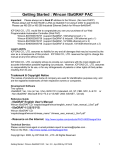
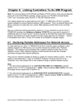
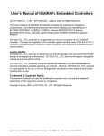
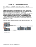
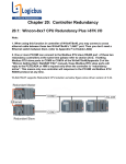
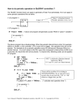
How to do Time Synchronization and record state of many ISaGRAF PAC ?
By [email protected]
1. Introduction
The method listed in this document is similar as www.icpdas.com – FAQ – Software – ISaGRAF –
065 . Here use one PC /Server to receive UDP report data from one or many ISAGRAF PAC
(i-7188EG, i-8xx7, iPAC-8x47, W-8xx7). Then the PC /Server can send time synchronization
command to the ISAGRAF PAC if it is necessary.
This demo sample apply one PC, IP = 10.0.0.91 , Mask = 255.255.255.0 to link to two ISaGRAF PAC
(can be any of W-8xx7, i-8x37, iPAC-8447 / 8847 or i-7188EG) in a local Ethernet area. The PAC 1 ‘s
IP = 10.0.0.103 , Mask = 255.255.255.0 , PAC 2 ‘s IP = 10.0.0.105 , Mask = 255.255.255.0
If this sample is applied in the Internet , then the PC / Server must set to a fixed Internet IP address.
And also each ISaGRAF PAC in the different local area should be possible to connect to the Internet
(Normally is through the Gateway Server of the ISP company) . Each ISaGRAF PAC (also named as
Local controller) must set their proper Gateway IP address.
Jul.2007 , Copyright by ICP DAS
2. Install software and hardware for demo testing
To run this demo sample correctly, please update your Controller’s ISaGRAF driver to below version.
http://www.icpdas.com/products/PAC/i-8000/isagraf-link.htm
i-7188EG:
i-8437 / 8837:
W-8xx7:
Ver. 2.19 or later version
Ver. 3.21 or later version
Ver. 3.38 or later version
Please visit www.icpdas.com – FAQ – Software – ISaGRAF – 070 to download the demo program.
If you want to know more about the UDP protocol used in this sample, please refer to the section 4.
The ISaGRAF demo programs used in this sample are as below.
PAC 1 : wdmo_64a.pia
(Please set PAC ‘s IP as 10.0.0.103 , Mask as 255.255.255.0)
PAC 2 : wdmo_64b.pia
(Please set PAC ‘s IP as 10.0.0.105 , Mask as 255.255.255.0)
Note: Sometimes PC / Server reside at the Internet with a fixed Internet IP address. Then all the local
controllers in the same application must assign its proper Gateway IP. The value of this ”Gateway IP”
can be found in a PC which is in the same local area with the local controller. First please set IP of that
PC as DHCP (Obtain an IP address automatically), then open a Command Prompt , key-in “ipconfig”
as below, then we got the Gateway IP setting.
If the PC resides at the Internet, it must use a fixed Internet IP. And also please modify the initial value
of the “IP_correct_PC” variable and modify the IO connection – udp_ip – “to_ip1” value in the
ISaRAF project “wdmo_64a” and “wdmo_64b” to be the same as that Internet IP. Then re-compile
them before downloading to the controller.
Jul.2007 , Copyright by ICP DAS
If successfully download ISaGRAF program, the below similar window will show up.
Date & Time of Local Controller
Auto-report Interval setting and progressing
“Msg1” is the message from Local Controller sent to the PC / Server.
“Msg2” is the reply message from the PC / Server to Local Controller.
“Msg_ip_addr” and “ip_port” are the source IP address and UDP port No. which sent
message to the local controller. Normally, it is the IP and port No. of the central PC /
Server. If it is not, that means some other un-friendly station or PC sending UDP data
to the Local Controller.
“R_Command” is the <command> field in the message from the PC / Server (Here in
this demo is 2 or 4)
Then please run VB 6.0 demo_8 program in your testing PC (refer to Section 3).
Jul.2007 , Copyright by ICP DAS
3. VB 6.0 demo program
Please finish the steps listed in section 2 first before doing the steps in this section.
Please set your PC ‘s IP address to a fixed IP = 10.0.0.91 , Mask = 255.255.255.0 for testing this demo.
(Because the ISaGRAF demo program “wdmo_64a” and “wdmo_64b” running in the Local Controller
will report message to the PC with IP = 10.0.0.91 and with UDP port No. = 12001)
The VB 6.0 demo program “demo_8.exe” resides at “.\vb6_demo\demo_8\”
(Please visit www.icpdas.com – FAQ – Software – ISaGRAF – 070 to download it.)
Please run MS. VB 6.0 development studio to open the source code of this “demo_8” , the file is
“.\vb6_demo\demo_8\demo_8.vbp”
After running this “demo_8.exe”, a “VB 6.0 Demo_8” window will show up as below. Please enter the
proper value of the following items and then click on “Start” to test it.
“UDP_port_No” is the UDP port No. which this PC is going to bind it to receive message coming from
local controllers (value can be 1001 to 65535). This demo uses value of 12001.
“Security_passwd” is the protocol security password . Value can be 0, or 1 to 2147483647, or
-2147483647 to -1. This demo uses value of 1234567 .
“Output_File_name” is an option. You may specify it or leave it empty. If specifying a name to it, then
demo_8.exe will create a new empty file to record all valid message from the local controllers.
Jul.2007 , Copyright by ICP DAS
How to test ?
The local controller will send message to the PC / Server when below events happen in this demo.
1. 15 seconds later after the Local controller is power up. (This only deliver once)
2. Send once at every minute past. (Continuously and periodically)
A. Please wait about 2 minutes after running “demo_8.exe”. If the PAC 1 or PAC 2 connection is Ok,
it will display “On Line” . If the PAC doesn’t report any message to the PC / Server over one
minute, it will display “No response …”
B. Please modify the time of this PC / Server. For example, two hours moving ahead, then wait about
one minute, you will see the connected PAC ‘s time will be modified to become the same time as the
PC / Server. The principle is every time the PAC sends message to the PC / Server, the PC / Server
will calculate the time difference. If it is larger than 20 seconds, the PC / Server will send a time
synchronization command to the PAC. If the application is applied in a local Ethernet area, you may
modify this allowed “time difference” to a smaller value, for example modifying from 20 to become 5
seconds. Please modify the below statement in the VB 6.0 demo_8 source code and re-compile it.
Modify
If Temp > 20 Or Temp < -20 Then
To become
If Temp > 5 Or Temp < -5 Then
C. Please observe if receiving a message every minute.
Jul.2007 , Copyright by ICP DAS
4. UDP protocol definition in the demo listed in this document
This protocol definition is valid for the ISaGRAF demo program “wdmo_64a” and “wdmo_64b” and
VB 6.0 demo program “demo_8” .
1. Local Controller is as UDP Client , while PC / Server is as UDP Server. Only Local Controller can
auto-send data (message/string) to the PC / Server (The message variable - “IP_correct_PC “ and
integer variable - “Port_correct_PC” in the ISaGRAF demo program “wdmo_64a” and
“wdmo_64b” specify the IP address and UDP port No. of the target PC / Server. And also there is
similar definition of the target PC / Server in the ISaGRAF IO connection window - “udp_ip” ).
2. PC / Server must reply a message with <Command> = 2 or 4 to the local controller in 15 seconds
after it receives a valid message from the local controller. The replied message must contain the
exact same <ID No.> as the <ID No.> it received from the local controller. The local controller will
drop the replied message with incorrect <ID No.>. If the local controller doesn’t receive a valid
replied message from the PC / Server in 15 seconds, it will send message once to the PC / Server
with a different <ID No.>. Then if PC / Server still not replied it in 15 seconds, local controller will
continuously send message again until it receives a valid replied message. (The timer variable “Timeout_interval” in the ISaGRAF demo program “wdmo_64a” and “wdmo_64b” defines this
Timeout value)
3. The local controller will send message to the PC / Server when below events happen in this demo.
(1) 15 seconds later after the Local controller is power up. (This only deliver once)
(2) Send once at every minute past. (Continuously and periodically)
4.
UDP message format of Local Controller sending to the PC / Server
Security_passwd: Must be specified as the same value in the ISaGRAF IO connection window –
“udp_ip” and in the VB demo program to communicate well. Value can be 0: means “No
encoding” (it is not safe) , or 1 to 2147483647, or -2147483647 to -1 (none-zero value means
“with encoding”, it is much safe).
If setting as a none-zero value, please refer to the “convert_to_udp_deliver_buf( )” ,
“convert_back_udp_deliver_buf( )” and “udp_ip_crc( )” function in the VB 6.0 “demo_8” for its
encoding algorithm.
If setting “Security_passwd” as 0, every delivered message can not exceed 255 bytes.
If setting “Security_passwd” as none-zero value, every delivered message can not exceed 259 bytes.
The last added 4-bytes is the <4-byte-Checksum > calculated by the “udp_ip_crc( )” function.
Local Controller will send the below format to the PC / Server.
Security_passwd is 0 :
(No 4-byte-Checksum at the end)
<Station_No of local controller>,<ID No.>,<Command>,
<Year>,<Month>,<Day>,<Hour>,<Minute>,<second>,
<User-defined CRC>
Jul.2007 , Copyright by ICP DAS
For example:
1001,850334470,1,2007,5,30,17,31,51,46677,18632
It means,
<Station_No of local controller> is 1001
<ID No.> is 850334470
<Command> is 1
Controller ‘s date and time is 2007/5/30 , 17:31:51
< User-defined CRC > is 46677,18632
Security_passwd is not 0 :
(With 4-byte-Checksum at the end)
<Station_No of local controller>,<ID No.>,<Command>,
<Year>,<Month>,<Day>,<Hour>,<Minute>,<second>,
<User-defined CRC><4-byte-Checksum>
<Command> definition:
1 : Local Controller report data to the PC / Server
<User-defined CRC> definition:
Can be defined as a different algorithm by the User. This demo apply the following algorithm
(Please apply a different algorithm in real application for safety)
Value is fixed as 11 bytes (Character) . It contains two value of 0 to 65535 separated by a “,”
For example,
value_1
0
1
21
321
4321
54321
value_2
0
1
21
321
4321
65535
:
:
:
:
:
:
fixed length of 11 bytes (Character)
'
0,
0' (with 4 Space Char. before ‘0’)
'
1,
1' (with 4 Space Char. before ‘1’)
' 21,
21' (with 3 Space Char. before ‘2’)
' 321, 321' (with 2 Space Char. before ‘3’)
' 4321, 4321'
(with 1 Space Char. before ‘4’)
'54321,65535' (No Space Char.)
Below steps - (a) to (d) is to get value 1, while - (e) is to get value 2
(Please apply a different algorithm in real application for safety)
(a) extract the string not including the <User-defined CRC> and <4-byte-Checksum>
into byte array - user_buf[ ] (for convient, we call this byte array as “user_buf[ ]” )
(b) replace user_buf[3] as user_buf[3] xor 100
That is
user_buf[3] = user_buf[3] ^ (unsigned char)100 ;
(user may use [2], [4], ... , and may be not using 100, ... whatever,
this depends on your own decision. Please use your own algorithm for safety.)
(c) replace user_buf[7] as user_buf[7] xor 200
That is
user_buf[7] = user_buf[7] ^ (unsigned char)200;
Jul.2007 , Copyright by ICP DAS
(user may use [5], [6], ... , and may not use 200, ... whatever,
this depends on your own decision. Please use your own algorithm for safety.)
(d) Calculate <User-defined CRC> as two byte => <CRC_Hi><CRC_Lo>
Then <User-defined CRC> = 256*<CRC_Hi> + <CRC_Lo>.
It is a value between 0 and 65535.
(e) using a different algorithm to get value 2
proceed (a) , then proceed (b) by using user_buf[4]=user_buf[4]^(unsigned char)48
then proceed (c) by using
user_buf[6]=user_buf[6]^(unsigned char)197
then proceed (d). Then we get value 2. It is a value between 0 and 65535.
(Please use your own algorithm for safety.)
5. UDP message format of the PC / Server replying to local controller
Security_passwd: Using the same definition as item 4.
PC / Server will reply below format to the local controller.
Security_passwd is 0 :
(No 4-byte-Checksum at the end)
<Station_No of PC/Server>,<Same ID No. from the local controller>,<Command>,
<Year>,<Month>,<Day>,<Hour>,<Minute>,<second>,
<User-defined CRC>
For example,
9001,519805546,2,2007,5,30,18,59,53, 6830,42679
It means,
< Station_No of PC/Server > is 9001
<ID No.> is 519805546
<Command> is 2
Date and Time in PC/Server is 2007/5/30 , 18:59:53
< User-defined CRC > is 6830,42679 (there is one Space Char. Before the first “6”)
Security_passwd is not 0 :
(With 4-byte-Checksum at the end)
<Station_No of PC/Server>,<Same ID No. from the local controller>,<Command>,
<Year>,<Month>,<Day>,<Hour>,<Minute>,<second>,
<User-defined CRC><4-byte-Checksum>
<Command> definition:
2 : to inform the local controller that PC / Server receive its correct data .
4 : to inform the local controller that its date and time differ more than 20 seconds than the
PC / Server, please adjust controller ‘s date and time and then send data to PC / Server
once again
<User-defined CRC> definition: Using the same definition as item 4.
Jul.2007 , Copyright by ICP DAS
5. Controller Ethernet security
5.1 : Modbus TCP/IP security
There are some ways user can get access to the Wincon-8xx7 via its ethernet port.
1. Using Modbus TCP protocol at port No.= 502. (ISaGRAF and other HMI can do this)
2. Using ftp (for example, keyin “ftp://10.0.0.103” on the Internet Explorer)
3. Using telent (for example, keyin “telnet 10.0.0.103 in the “command” window)
4. Using the Web server (The Web HMI does)
Note:
1. While for i-8437-80 / 8837-80, i-8437/8837 and i-7188EG, only item 1 is possible.
2. If the controller is W-8x47/8x46, when using “ftp”, “telnet”, “Web HMI” & “Modbus TCP/IP”,
please connect your PC/HMI to W-8x47/8x46’s “LAN1” port, and please use “NS-205” or “NS-208”
Ethernet switch.
For safety, recommend to disable item 2 and 3 at run time for Wincon.
Check it to disable.
And about item 4, please set proper username & password for the Wincon Web HMI.
Setting user name &
password here
Jul.2007 , Copyright by ICP DAS
About item 1, user may set up to 8 IP address for ISaGRAF or other HMI to get access to the I-8x37,
I-7188EG & W-8xx7 via the Modbus TCP/IP protocol as below.
On the IO connection window of ISaGRAF, please connect “vip” and entering the IP which can get
access to the controller via Modbus TCP/IP protocol. If “vip” is not connected, any remote IP can get
access to your controller via Modbus TCP/IP protocol. If “vip” is connected and No IP is entered (all
assigned as “N/A”), No HMI and ISaGRAF can get access to it by Modbus TCP/IP anymore.
Jul.2007 , Copyright by ICP DAS
5.2 : Using “dis_stop” to disable / enable the ISaGRAF Download function
For some reason, to prevent someone to use ISaGRAF software to stop or to download a different
controller project already running in the i-7188EG , I-8437/8837 and W-8xx7, the “Dis_stop” can be
applied . Please connect “dis_stop” at a slot No. larger than 8 and init the channel value to become
TRUE. Then stop / download command is not allowed in this controller.
To disable “Dis_stop” to accept stop / download command, please run the original ISaGRAF project to
link to this controller and set the channel value to become False.
Jul.2007 , Copyright by ICP DAS