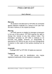
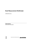
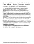
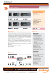
1
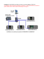
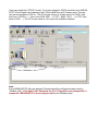
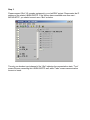
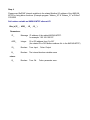
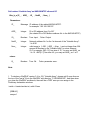
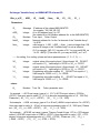
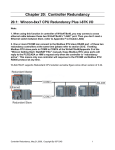
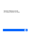
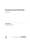
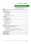
Connecting i-8KE4/8-MTCP Ethernet I/O
Wincon-8x37/8x36 & Wincon-8x47/8x46 supports i-8KE4-MTCP & i-8KE8-MTCP
ethernet I/O since Wincon ISaGRAF driver version 3.32B. Please visit below web site.
One Wincon-8xx7/8xx6 can connect max. 24 nodes of i-8KE4/8-MTCP. The Ethernet I/O
scan time of 3000 ~ 6000 Ch. for one W-8x47 / 8x46 is about 30 to 40 ms. If connecting less
than 10 nodes of I-8KE4/8-MTCP, the Ethernet I/O scan time is about 20 ms. However, it still
depends on how big (complex) of your logic program. (The Ethernet I/O scan time of one
W-8x36 / 8x37 is about twice of the W-8x47 / 8x46. That means W-8x36 / 8x37 is slower
than W-8x47 / 8x46 when connecting Ethernet I/O)
Configure1: W-8x47/8x46 (Dual Ethernet version) connecting Modbus TCP/IP I/O in a safelocal-private network .
1
Configure2: W-8x47/8x46 (Dual Ethernet) connecting Modbus TCP/IP I/O in both two ports.
Configure3: W-8x37/8x36 (One Ethernet version) connecting Modbus TCP/IP I/O.
This configure doesn't have the advantage of configure 2 . And if the NS-208 is connected to
public network, then it doesn't have the advantage of configure 1.
How to use ?
Step 1.
The first step is to assign an unique IP address to all of the i8KE4/8-MTCP.
Please power off the i8KE4/8-MTCP, short its “INIT” to “INIT * COM”, and then power it up.
Then please run “7188xw.exe” on PC ( “7188xw.exe” is burned in I-8000 CD-ROM or can be
download.
Press some <Enter> , and then type “ip” to view the current IP setting. Then type in for
example, “ip 192.168.2.70” to set an IP address to it.
To set mask address, please type in for example, “mask 255.255.255.0”
Step 2.
The second step is to configure all of the connecting i8KE4/8-MTCP by running “Modbus
utility”. The Modbus utility is burned in the I-8000 CD-ROM or can be download.
Every i8KE4/8-MTCP with new plugged IO board should be configured at least once by
“Modbus utility”. If the 2nd & 3rd Leds below the Five 7-Segment-Led is always blink, it
means this i-8KE4/8-MTCP is not configured well by the “Modbus utility”
Enter the correct IP of the i8KE4/8-MTCP on the Modbus utility, and then click on “Connect”.
If the i8KE4/8-MTC is well connectted, You will see the Modbus address assigned in the i8KE4/8-MTCP. For example, D/I starting from 0 to ... , A/I starting from 0 to ...
There is a Watchdog setting for the i-8KE4/8-MTCP. The default value is “disable the
watchdog” . You may enable it by assigning a “Watchdog timer” value , for example from 10
to 60 seconds. This will automatically set the Digital outputs and Analog outputs of the i8KE4/8-MTCP to a pre-defined “Safe Value” when the Ethernet communication between the
Wincon and the i-8KE4/8-MTCP is break. If you check the Ch0 to ... of the “Safe Value”, it
means to set these Channels to have a safe value of “ON” , if you un-check it, it means the
related channel has safe value of “OFF”. The “Safe value” function only works when you
assign a value larger than zero to the “Watchdog timer” and the communication is break.
User may enable the “87K DI Counter” if you have plugged i-87K D/I module in the i-8KE4/8MTCP. Every Digital Input channel pf the i-87K module have a DI Counter value. The max
rate can be accepted is 100 Hz . The DI Counter value is a 16-bits value (0 to 32767, and
then from -32768 to -1, Hex is from 0000, 0001 ... to 7FFF , 8000 , 8001, ... to FFFF, then
back to 0000, ...). The DI Counter value is a A/I value with a Modbus address.
Note:
Every i8KE4/8-MTCP with new plugged IO board should be configured at least once by
“Modbus utility”. If the 2nd & 3rd Leds below the Five 7-Segment-Led is always blink, it
means this i-8KE4/8-MTCP is not configured well by the “Modbus utility”
Step 3.
Please connect “i8ke” I/O complex equipment in your IsaGRAF project. Please enter the IP
address of the related i-8KE4/8-MTCP. If the Wincon has connectted more than one i8KE4/8-MTCP, you should connect more “i8ke” as below.
The only one boolean input channel of the “i8ke” indicates its communication state. “True”
means Wincon connecting this I-8KE4/8-MTCP well, while “Fasle” means communication
timeout or break.
Step 4.
Please map ISaGRAF internal variables to the related Modbus I/O address of the i-8KE4/8MTCP by using below functions. (Example program “Wdemo_30” & “Wdemo_31” at W-8xx7
CD-ROM.
Set boolean variable as i8KE4/8-MTCP ethernet I/O
i8ke_b( IP_ , ADR_ , IO_ , B_ )
Parameters:
IP_
Message IP address of the related i8KE4/8-MTCP.
for example: '192.168.100.123'
ADR_
Integer
DI or DO address from 0 to 267
(the related DI or DO Modbus address No. in the i8KE4/8-MTCP)
IO_
Boolean
True: Input , False: Output
B_
Boolean
The internal boolean vairable name
Boolean
True: Ok.
return:
Q_
False: parameter error.
Set Integer variable as i8KE4/8-MTCP ethernet I/O
i8ke_n( IP_ , ADR_ , IO_ , N_ , X0_ , Y0_ , X1_ , Y1_ )
Parameters:
IP_
Message
ADR_
Integer
IO_
N_
Boolean
Integer
IP address of the related i8KE4/8-MTCP.
for example: '192.168.100.123'
AI or AO address from 0 to 127
(the related AI or AO Modbus address No. in the i8KE4/8-MTCP)
True: Input , False: Output
The internal Integer vairable name
----- for scaling, if no scaling, please set below parameters as ( 0 , 0 , 0 , 0 ) ----X0_
Integer
Y0_
Integer
X1_
Integer
Y1_
Integer
original value of the analog Input / Output board. X0_ DO NOT
not equal to Y0_ . Valid range is -32768 <= X0_ <= +32767
original value of the analog Input / Output board. X0_ DO NOT
not equal to Y0_ . Valid range is -32768 <= Y0_ <= +32767
Engineering value after scalling. X1_ DO NOT not equal to Y1_ .
Valid range is -30000 <= X1_ <= +30000
Engineering value after scalling. X1_ DO NOT not equal to Y1_ .
Valid range is -30000 <= Y1_ <= +30000
return:
Q_
Boolean
True: Ok.
False: parameter error.
1st example - i-8017h set range_type as '+/- 10 V' (i-8017h's input value is -32768 to
+32767). User may want to scale ( 0 , 10 V) to become engineering value of ( 0 , 1000 Psi).
Please set ( X0_ , Y0_ ) = ( 0 , +32767) , ( X1_ , Y1_ ) = ( 0 , 1000)
2nd example - i-8024 set range_type as '0 to 20 mA' (i-8024's output value is 0 to +32767).
User may want to scale ( 4 , 20 mA) to become engineering value of ( 0 , 3000 rpm). Please
set ( X0_ , Y0_ ) = ( 6553 , +32767) , ( X1_ , Y1_ ) = ( 0 , 3000)
3rd example - i-87018R set range_type as 'Thermo-Couple K-type: -270 to +1372 degree
celsius' (i-87018R's input value is -6448 to +32767). User may want to scale ( -270 , +1372
degree) to become engineering value of ( -2700 , +13720 ). Please set ( X0_ , Y0_ ) =
( -6448 , +32767) , ( X1_ , Y1_ ) = ( -2700 , +13720)
4th example - i-87024 set range_type as '4 to 20 mA' (i-87024's output value is 0 to
+32767). User may want to scale ( 4 , 20 mA) to become engineering value of ( 0 , 5000
rpm ). Please set ( X0_ , Y0_ ) = ( 0 , +32767) , ( X1_ , Y1_ ) = ( 0 , 5000)
Set REAL variable as i8KE4/8-MTCP ethernet I/O
i8ke_f( IP_ , ADR_ , IO_ , F_ , X0_ , Y0_ , XF1_ , YF1_ )
Parameters:
IP_
Message
ADR_
Integer
IO_
F_
Boolean
REAL
IP address of the related i8KE4/8-MTCP.
for example: '192.168.100.123'
AI or AO address from 0 to 127
(the related AI or AO Modbus address No. in the i8KE4/8-MTCP)
True: Input , False: Output
The internal REAL vairable name
----- for scaling, if no scaling, please set below parameters as ( 0 , 0 , 0.0 , 0.0 ) ----X0_
Integer
Y0_
Integer
XF1_
REAL
YF1_
REAL
original value of the analog Input / Output board. X0_ DO NOT
equal to Y0_. Valid range is -32768 <= X0_ <= +32767
original value of the analog Input / Output board. X0_ DO NOT
equal to Y0_. Valid range is -32768 <= Y0_ <= +32767
Engineering value after scalling.
XF1_ DO NOT equal to YF1_ .
Engineering value after scalling.
XF1_ DO NOT equal to YF1_ .
return:
Q_
Boolean
True: Ok.
False: parameter error.
1st example - i-8017h set range_type as '+/- 10 V' (i-8017h's input value is -32768 to
+32767). User may want to scale ( 0 , 10 V) to become engineering value of ( 0 , 1000 Psi).
Please set ( X0_ , Y0_ ) = ( 0 , +32767) , ( XF1_ , YF1_ ) = ( 0.0 , 1000.0 )
2nd example - i-8024 set range_type as '0 to 20 mA' (i-8024's output value is 0 to +32767).
User may want to scale ( 4 , 20 mA) to become engineering value of ( 0 , 3000 rpm). Please
set ( X0_ , Y0_ ) = ( 6553 , +32767) , ( XF1_ , YF1_ ) = ( 0.0 , 3000.0 )
3rd example - i-87018R set range_type as 'Thermo-Couple K-type: -270 to +1372 degree
celsius' (i-87018R's input value is -6448 to +32767). User may want to scale ( -270 , +1372
degree) to become engineering value of ( -270.0 , +1372.0 ). Please set ( X0_ , Y0_ ) =
( -6448 , +32767) , ( XF1_ , YF1_ ) = ( -270.0 , +1372.0)
4th example - i-87024 set range_type as '4 to 20 mA' (i-87024's output value is 0 to
+32767). User may want to scale ( 4 , 20 mA) to become engineering value of ( 0 , 5000
rpm ). Please set ( X0_ , Y0_ ) = ( 0 , +32767) , ( XF1_ , YF1_ ) = ( 0.0 , 5000.0 )
Set boolean 'Variable Array' as i8KE4/8-MTCP ethernet I/O
i8ke_b_a( IP_ , ADR_ , IO_ , NetW_ , Num_ )
Parameters:
IP_
Message IP address of the related i8KE4/8-MTCP.
for example: '192.168.100.123'
ADR_
Integer
DI or DO address from 0 to 267
(the related DI or DO Modbus address No. in the i8KE4/8-MTCP)
IO_
Boolean
True: Input , False: Output
NetW_
Integer
Num_
Integer
Network address No. for the 1st element of the "Variable Array".
1 to 8191
valid range is 1~255 . ( ADR_ + Num_ ) cant not larger than 264.
amount of Boolean in the "Variable Array" to set as ethernet
IO, For example Bi[0..15] has size of 16, You may set NUM_ as
1 to 16. ABC[0..7] has size of 8, you may set NUM_ as 1 to 8
return:
Q_
Boolean
True: Ok.
False: parameter error.
Note:
1. To declare a ISaGRAF version 3.4 (or 3.5) "Variable Array", please add 2 more lines on
the top of the "isa.ini" file in the ISaGRAF sub-directory "C:\ISAWIN\EXE\". And then when
you open the ISaGRAF workbench, there will be a "DIM" area you can assign in the
Dictionary declaration windows.
inside c:\isawin\exe\isa.ini, adds 2 lines
[DEBUG]
arrays=1
Set integer 'Variable Array' as i8KE4/8-MTCP ethernet I/O
i8ke_n_a( IP_ , ADR_ , IO_ , NetW_ , Num_ , X0_ , Y0_ , X1_ , Y1_ )
Parameters:
IP_
Message
ADR_
Integer
IO_
NetW_
Boolean
Integer
Num_
Integer
IP address of the related i8KE4/8-MTCP.
for example: '192.168.100.123'
AI or AO address from 0 to 127
(the related AI or AO Modbus address No. in the i8KE4/8-MTCP)
True: Input , False: Output
Network address No. for the 1st element of the "Variable Array".
1 to 8191
valid range is 1~255 . ( ADR_ + Num_ ) cant not larger than 128.
amount of Integer in the "Variable Array" to set as ethernet
IO, For example Ni[0..31] has size of 32, You may set NUM_ as
1 to 32. ABC[0..7] has size of 8, you may set NUM_ as 1 to 8
----- for scaling, if no scaling, please set below parameters as ( 0 , 0 , 0 , 0 ) ----X0_
Integer
Y0_
Integer
X1_
Integer
Y1_
Integer
original value of the analog Input / Output board. X0_ DO NOT
not equal to Y0_ . Valid range is -32768 <= X0_ <= +32767
original value of the analog Input / Output board. X0_ DO NOT
not equal to Y0_ . Valid range is -32768 <= Y0_ <= +32767
Engineering value after scalling. X1_ DO NOT not equal to Y1_ .
Valid range is -30000 <= X1_ <= +30000
Engineering value after scalling. X1_ DO NOT not equal to Y1_ .
Valid range is -30000 <= Y1_ <= +30000
return:
Q_
Boolean
True: Ok.
False: parameter error.
1st example - i-8017h set range_type as '+/- 10 V' (i-8017h's input value is -32768 to
+32767). User may want to scale ( 0 , 10 V) to become engineering value of ( 0 , 1000 Psi).
Please set ( X0_ , Y0_ ) = ( 0 , +32767) , ( X1_ , Y1_ ) = ( 0 , 1000)
2nd example - i-8024 set range_type as '0 to 20 mA' (i-8024's output value is 0 to +32767).
User may want to scale ( 4 , 20 mA) to become engineering value of ( 0 , 3000 rpm). Please
set ( X0_ , Y0_ ) = ( 6553 , +32767) , ( X1_ , Y1_ ) = ( 0 , 3000)
3rd example - i-87018R set range_type as 'Thermo-Couple K-type: -270 to +1372 degree
celsius' (i-87018R's input value is -6448 to +32767). User may want to scale ( -270 , +1372
degree) to become engineering value of ( -2700 , +13720 ). Please set ( X0_ , Y0_ ) =
( -6448 , +32767) , ( X1_ , Y1_ ) = ( -2700 , +13720)
13
Set REAL 'Variable Array' as i8KE4/8-MTCP ethernet I/O
i8ke_f_a( IP_ , ADR_ , IO_ , NetW_ , Num_ , X0_ , Y0_ , XF1_ , YF1_ )
Parameters:
IP_
Message
ADR_
Integer
IO_
NetW_
Boolean
Integer
Num_
Integer
IP address of the related i8KE4/8-MTCP.
for example: '192.168.100.123'
AI or AO address from 0 to 127
(the related AI or AO Modbus address No. in the i8KE4/8-MTCP)
True: Input , False: Output
Network address No. for the 1st element of the "Variable Array".
1 to 8191
valid range is 1~255 . ( ADR_ + Num_ ) cant not larger than 128.
amount of REAL in the "Variable Array" to set as ethernet
IO, For example Ri[0..11] has size of 12, You may set NUM_ as
1 to 12.
----- for scaling, if no scaling, please set below parameters as ( 0 , 0 , 0.0 , 0.0 ) ----X0_
Integer
Y0_
Integer
XF1_
REAL
YF1_
REAL
original value of the analog Input / Output board. X0_ DO NOT
equal to Y0_. Valid range is -32768 <= X0_ <= +32767
original value of the analog Input / Output board. X0_ DO NOT
equal to Y0_. Valid range is -32768 <= Y0_ <= +32767
Engineering value after scalling.
XF1_ DO NOT equal to YF1_ .
Engineering value after scalling.
XF1_ DO NOT equal to YF1_ .
return:
Q_
Boolean
True: Ok.
False: parameter error.
1st example - i-8017h set range_type as '+/- 10 V' (i-8017h's input value is -32768 to
+32767). User may want to scale ( 0 , 10 V) to become engineering value of ( 0 , 1000 Psi).
Please set ( X0_ , Y0_ ) = ( 0 , +32767) , ( XF1_ , YF1_ ) = ( 0.0 , 1000.0 )
2nd example - i-8024 set range_type as '0 to 20 mA' (i-8024's output value is 0 to +32767).
User may want to scale ( 4 , 20 mA) to become engineering value of ( 0 , 3000 rpm). Please
set ( X0_ , Y0_ ) = ( 6553 , +32767) , ( XF1_ , YF1_ ) = ( 0.0 , 3000.0 )
3rd example - i-87018R set range_type as 'Thermo-Couple K-type: -270 to +1372 degree
celsius' (i-87018R's input value is -6448 to +32767). User may want to scale ( -270 , +1372
degree) to become engineering value of ( -270.0 , +1372.0 ). Please set ( X0_ , Y0_ ) =
( -6448 , +32767) , ( XF1_ , YF1_ ) = ( -270.0 , +1372.0)