1
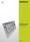
CNC PILOT 640
The Contouring Control for
Lathes and Turning-Milling
Machines
September 2015
Start smart
For years, lathe controls from
HEIDENHAIN have been proving
themselves on compact, but also complex
lathes. They distinguish themselves
particularly with their convenient and
simple programming as well as their highquality, ergonomic operating components.
This brochure describes the functions and
specifications of the CNC PILOT 640 with NC
software 68894x-03.
2
Contents
The CNC PILOT 640...
Where can it be used?
4
Versatile and powerful
– CNC PILOT 640
What does it look like?
6
Well designed and user friendly
– The CNC PILOT 640 in dialog with the user
What can it do?
8
Quick and reliable machining with high contour accuracy
– Uniformly digital control design
– Intelligent supervision with load monitoring
10
Effective, clearly organized and flexible
– Simple programming with smart.Turn
– Powerful NC programs with DIN PLUS
– NC program at the push of a button with TURN PLUS
16
Describing and importing contours
– ICP Interactive Contour Programming
18
Realistic testing before machining
– Graphic simulation
20
Expandable for complex tasks
– Turning, drilling and milling in one setup
– Full-surface machining including the C axis and Y axis
– Working in a tilted plane with the B axis
26
Powerful Teach-in mode
– Cycles with preprogrammed working steps
28
Fast availability of tool data and cutting data
– The tool and technology database of the CNC PILOT 640
30
Open for communication
–
–
–
–
Fast data transfer with the CNC PILOT 640
Display any file formats on the control screen
The DataPilot CP 640 programming station
Fast availability of all information
34
Workpiece measurement
– Setup, presetting and measuring with touch trigger probes
35
Tool Measurement
– Measuring length, radius and wear directly in the machine
... At a glance
36
Overview
–
–
–
–
User functions
Options
Accessories
Specifications
3
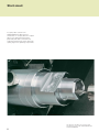
Versatile and powerful
– CNC PILOT 640, the contouring control for lathes and
turning-milling machines
Thanks to its flexible design and numerous
programming features, the CNC PILOT 640
always gives you optimum support.
Regardless of whether you are
manufacturing single parts or batches,
simple or complex workpieces, the
CNC PILOT 640 is characterized by its
simple operation and programming. It is
quickly learned and requires minimum
training time.
The CNC PILOT 640 was conceived for
CNC lathes. It is suitable for horizontal and
vertical lathes.
The CNC PILOT 640 supports lathes with
main and opposing spindle, one slide (X
and Z axis), C axis or positionable spindle,
driven tools, and machines with Y and B
axes.
4
TC
X1/Z1
B1/Y1
W
Regardless of whether you are turning
simple parts or complex workpieces, the
CNC PILOT 640 provides you with the
benefits of graphical contour input and
convenient programming with smart.Turn.
Programming with variables, controlling
special machine components, or using
externally created programs, etc. is no
problem: simply switch to DIN PLUS. With
DIN PLUS you’ll find the solution for your
special tasks.
From simple jobs on a
compact machine ...
... to complex tasks
... to large batch
production
5
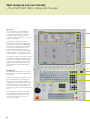
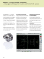
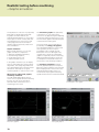
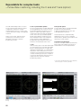
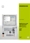
Well designed and user friendly
– The CNC PILOT 640 in dialog with the user
The screen
The 19-inch TFT color flat-panel display
shows a clear overview of all relevant
information for programming, operating
and inspecting the machine tool and
control such as program blocks, comments
and error messages.
During program input the required
parameters are illustrated in help graphics,
and during Test Run the CNC PILOT 640
simulates the cutting process in full detail
on the screen. During program run the
screen displays information on the tool
position, the rotational speed, the feed rate
and the utilization of the drives as well as
further information on the machine status.
The positions of the tool are shown in large
characters. The respective distance-to-go,
the feed rate, the spindle speed and the ID
number of the current tool are also clearly
visible. A moving-bar diagram shows the
current utilization of the spindle and the
axis drives.
The keyboard
The CNC PILOT 640 needs very few keys.
Easily understood symbols clearly indicate
the functions.
The keys on the numeric keypad are used
both for data input and for selecting the
functions. The menu window displays the
available functions graphically. The function
keys below the screen are used to modify
the selected functions, assume position
and technology values, and control the data
input.
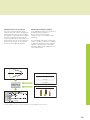
As an alternative, the CNC PILOT 640 is
also available with a 15-inch screen and
matching control panel. The PLC soft-key
row on the left side of the monitor is
missing in this version.
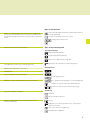
6
Keys on the monitor
Switch the help graphics between outside/inside machining
(cycle programming)
Display of operating modes and machine status (configurable)
You can choose a suitable function for each of the 16 fields, and
save different display assignments for the automatic and manual
mode.
Soft keys for selecting functions on screen
Shift between soft-key rows
PLC function keys for machine functions
Keys on the control panel
Operating mode keys
Machine Operating Modes
Programming Operating Modes
Tables for tool data and technology data
Parameters, file management, transfer, diagnostics
Self-explanatory function keys for NC programming
Navigation keys
Alphanumeric keyboard for comments
USB interface
Keys for operating modes and functions
Screen/page up/down
Go to beginning of program/list or to end of program/list
Keypad for numerical input and fast, direct menu selection
smart.Turn: switches to the next detail input form
smart.Turn: switches to the previous/next group
Keys and touchpad for navigation
Special keys
CALC
ERR
Calculator
Call up messages and errors
Info key
Machine operating panel with override potentiometer and
electronic handwheel
GOTO
Display block or activate special functions, such as input
options or text input
Save screen contents as graphic file
Expanded input capabilities
7
Quick and reliable machining with high contour accuracy
– Uniformly digital control design
Thanks to its digital design, the
CNC PILOT 640 has control over the
machine’s entire drive system. Not only
does the field-proven digital drive
technology from HEIDENHAIN make high
contour accuracy and rapid machining at
high speeds possible, but also all control
components of the CNC PILOT 640 are
connected via digital interfaces.
Digital drive technology
The position controller, speed controller
and, if required, the current controller are
integrated in the CNC PILOT 640. The
digital motor control makes it possible
to attain very high feed rates.
High contour accuracy
The CNC PILOT 640 dynamically calculates
the contour in advance. This enables it to
adapt the axis velocities early enough to
the contour transitions. It controls the axes
with special algorithms that ensure path
control with the required limits to velocity
and acceleration.
High availability
In the uniformly digital control concept of
the CNC PILOT 640, all components are
connected to each other via purely digital
interfaces: The control components are
connected via HSCI (HEIDENHAIN Serial
Controller Interface), the real-time protocol
from HEIDENHAIN for Fast Ethernet, and
the encoders are connected via EnDat2.2,
the bidirectional interface from
HEIDENHAIN.
This achieves a high degree of availability
for the entire system. It can be diagnosed
and is immune to noise—for everything
from the main computer to the encoder.
The uniformly digital design from
HEIDENHAIN guarantees not just very
high accuracy and surface quality, but high
traverse speeds as well.
Rotary encoder
Inverter
Main computer
MC
HSCI
Controller unit
CC
PWM
Motor
Linear encoder
EnDat 2.2
HSCI
EnDat 2.2
EnDat 2.2
HSCI
Operating panel
8
HSCI
PL
PL
Angle encoder
– Intelligent supervision with load monitoring (option)
Load monitoring—detecting tool wear
and breakage during machining*
The load monitor observes the machine’s
spindle and motor load while comparing
them with the utilization values of a
reference operation. The CNC PILOT 640
can graphically display the utilization rates
in a separate window.
You can set two limit values that trigger
different error reactions. After the first limit
value is exceeded, the current tool is
flagged as worn out and the control
automatically exchanges it on the next tool
call with a predefined replacement tool.
After the second limit is exceeded, the
CNC PILOT 640 assumes that there is an
impermissible load (e.g. tool breakage) and
stops the machining process. This
improves process reliability during
machining, in particular during unmanned
shifts.
* These functions must be implemented in the
machine and control by the machine tool
builder.
Graphic display of the load values
9
Effective, clearly organized and flexible
– Simple programming with smart.Turn (option)
Has the safety clearance been correctly
entered, is the speed limit taken into
account, how are oversizes defined? All
this needs to be considered not only by
the beginner, but also by the experienced
NC programmer when creating conventional
DIN programs.
The smart.Turn principle
The working block—called a unit—plays
the central role in smart.Turn programs. A
unit describes a machining step completely
and unambiguously. The unit includes the
tool call, the technology data, the cycle call,
the approach and departure strategies as
well as global data, such as safety
clearance, etc. All these parameters are
summarized in one, clearly structured
dialog box.
The unit
All parameters of a smart.Turn unit are
united in simple and well designed fillable
forms. The overview form shows you a
summary of the selected unit, and
subforms provide information on the
details of a working block. Clearly arranged
help graphics illustrate all required input. If
input options are available, smart.Turn
displays a list of the available options for
selection.
By the way: You do not need to stop the
manufacturing process for programming
with smart.Turn. You can create and test
the smart.Turn program while the program
is running.
The smart.Turn principle gives you the
reassurance that the working block is
defined correctly and completely. In the
NC program, smart.Turn lists the DIN PLUS
commands of the unit. This gives you an
overview of all working-block details at any
time.
Straightforward dialogs;
help graphics illustrate the parameters.
smart.Turn unit in the NC program
Input form in smart.Turn
10
Structured and easy-to-read
Clearly structured and easy-to-read—these
are the characteristics of smart.Turn
programs. smart.Turn uses section codes
that clearly distinguish between the
program head with setup information,
the turret assignment, the workpiece
description and the actual machining
operation.
Under dialog guidance, you enter in the
following order:
• Program head
• Tool assignment in the turret
• Workpiece-blank definition
• Description of machined part
• Individual machining steps
The smart.Turn technique not only ensures
that the program is easy to read, it also
makes it possible to save all information
required for producing the workpiece in the
NC program.
smart.Turn program with section codes
Production data at a glance
The program head includes all important
information on the workpiece, e.g. drawing
number, date, programmer, material,
fixture, etc.
All information that is important for setting
up and machining the workpiece, such as
the tool assignment in the turret, is
included in the part program.
Programming in more than one window
Up to six NC programs can be opened
simultaneously in the DIN PLUS editor. The
part program to be displayed is selected
using the smart keys. This enables you to
transfer program blocks from one part
program to another and allows you to
quickly get an overview of complex part
programs including subprograms.
Input form for program head
11
Effective, clearly organized and flexible
– Simple programming with smart.Turn (option)
Programming made simple
Global parameters, such as oversizes,
safety clearances, coolants, etc., are
defined once in the start unit. Then smart.
Turn transfers these parameters to the
other units.
In the NC program, smart.Turn lists the
DIN PLUS commands of the unit. This not
only gives you an overview of all workingblock details, but you also have a clearly
legible and well-structured NC program.
Programming Contours
smart.Turn enables you to work simply and
flexibly. Simple contours can be defined
with just a few entries in the cycle. Complex
contours are described with ICP graphic
interactive programming. Workpiece
descriptions that are available in DXF
format can be easily imported. Contours
are saved in the NC program in a
consistently legible and editable form. This
gives you the benefit of choosing either
smart.Turn or the ICP editor to edit the
programs.
smart.Turn supports units for roughing,
finishing, recessing, recess turning, thread
cutting, boring, drilling, tapping, and milling,
as well as special units for program start,
program end, moving the C axis in/out,
subprograms and program section repeats.
Technology data as default values
The CNC PILOT 640 saves your cutting
data according to the criteria of workpiece
material, tool material and machining
mode. As you have already entered the
cutting material in the tool definition, you
need only enter the material of your
workpiece. This provides smart.Turn with
all data for setting default values for the
cutting data.
smart.Turn dialogs with help graphic
12
Contour follow-up
Another highlight of the CNC PILOT 640 is
the contour follow-up feature. If you define
the workpiece blank at the beginning of
your smart.Turn or DIN PLUS program, the
control then computes the new blank for
each new cut. The machining cycles always
adapt to the current workpiece blank. The
contour follow-up helps you to avoid air
cuts and optimize approach paths, even if
the workpiece material has been previously
removed.
– Powerful NC programs with DIN PLUS
Programming in DIN PLUS
smart.Turn offers units for all machining
tasks as well as units for special functions.
If you want to control special machine
components, or use the variable
programming function or other complex
functions that are not provided by smart.
Turn, DIN PLUS will support you. It
provides powerful machining cycles,
program branches and programming with
variables. You can switch back and forth
between the smart.Turn and DIN PLUS
programming modes within a program.
Because the units are based on DIN PLUS,
you can break up a unit into blocks at any
time to modify and optimize the resulting
DIN PLUS program section.
Of course the CNC PILOT 640 also allows
you to create a DIN program, or to import
and use externally created programs.
Powerful cycles in DIN PLUS
In the fixed cycles of DIN PLUS you define
the contour section to be machined. You
simply mark the area to be machined in the
control graphic. Then you can test each
work step immediately in the simulation.
You select the respective commands from
a menu or enter them directly with G
codes. The screen displays a dialog box in
which you enter the related parameters. All
input is explained on screen in plain
language and with graphic illustrations.
Thanks to the powerful fixed cycles and
the assignment of cycles to machining
sections, with DIN PLUS you dramatically
improve effectiveness and flexibility
compared to conventional part
programming.
smart.Turn program with display of menu item for breaking up a smart.Turn unit
13
Effective, clearly organized and flexible
– NC program at the push of a button with TURN PLUS (option)
With TURN PLUS you can create part
programs in a very short time. After you
have entered the contour of the blank and
finished part, you only need to select the
material and clamping devices. TURNPLUS
does everything else automatically: it
generates the working plan, selects the
machining strategy, selects the tools and
cutting data, and generates the NC blocks.
Your result is a comprehensively
commented smart.Turn program with
working blocks (units). That gives you the
assurance you need for optimization and
safety when you're breaking in the part
program.
TURN PLUS can do all that for milling,
drilling and boring operations with the C or
Y axis on face and cylindrical surfaces as
well as on rear-face surfaces in machines
with opposing spindles.
14
The part program at a keystroke
If short programming times are important
to you, you can generate all machining
steps by pressing a single key. On the
basis of the contour entered and the
information from the technological
database, TURN PLUS independently
prepares the working plan and chooses
suitable machining strategies, tools and
cutting data. The whole operation takes
only a few seconds. You can monitor each
individual step in the control graphics.
TURN PLUS uses a reasonable sequence
of possible operations, such as “first
roughing transverse, then roughing
longitudinal” or “finishing outside, then
finishing inside.” However, you can also
adapt this sequence yourself to suit various
tasks. In this way the CNC PILOT 640 can
profit from your company’s machining
know-how even during the automatic
working plan generation.
Automatic program generation for
full-surface machining
The CNC PILOT 640 automatically
generates the part program even for
complex workpieces that need to be
machined on the front face, back face, and
lateral surfaces. After defining the
geometry, this can save you about 90 % of
the time otherwise needed to create a
program.
Automatic program generation for the
second setup
TURN PLUS knows the contour of the
clamping devices when it generates the
working plan. It automatically limits the tool
path to a safe distance from the clamping
device. When the program for the first
setup is completed, you can “rechuck”
using interactive graphics. The control then
automatically generates the program for
the second setup using the workpiece
geometry that has already been entered.
Inclined contours are no problem
The control is presented with special
requirements when it has to generate the
part program for inclined contours. Often,
the angle the contour falls off at is steeper
than the tool tip angle. In that case the
control automatically chooses another tool
and machines the contour in the opposite
direction or as a recess. In any case the
result is an executable part program.
Defining the machining sequence
In the TURN PLUS dialog you can define a
standard machining sequence.
You can save various machining
sequences, e.g for chuck parts or shaft
machining.
From the global main types of machining,
such as “roughing,” “finishing,” or “drilling,”
to details like defining a tool for a specific
operation—the automatic working plan
generation (AWG) can be adapted to the
user’s requirements.
Technology
Material
Velocity
Feed rate
Tools
Go with TURN PLUS in the shortest possible time from programming to the first cut
15
Describing and importing contours
– ICP interactive contour programming
For jobs that cannot be machined with the
standard cycles because of the complexity
of the workpiece or the lack of certain
dimensions in the workpiece drawing,
you need ICP, the interactive contour
programming. You describe the contour
elements directly as they appear in the
workpiece drawing. Or—if the drawing is
available in DXF format—you simply import
the contour.
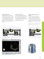
Contour programming with ICP
You define an ICP contour by entering the
contour elements one after the other in the
graphic editor. When selecting the contour
elements, you already specify the direction
of the line or the direction of rotation of the
circular arc. This way the CNC PILOT 640
needs very little information about the
contour element.
When entering the data, you decide
whether the coordinates are absolute or
incremental, and whether you enter the
end point or the length of the line or the
center point or the radius of a circular arc.
You also specify whether the path to the
next contour element should be tangential
or non-tangential.
Define the contour element in ICP.
16
As long as they are mathematically
defined, the CNC PILOT 640 calculates
missing coordinates, intersections, center
points, etc. If the entered data permit
several mathematically possible solutions,
you can view the individual solutions and
then select the proposal that matches the
drawing. You can modify or change existing
contours.
Superimposing form elements
The ICP editor recognizes the chamfer,
rounding and undercut form elements
(DIN 76, DIN 509 E, DIN 509 F, etc.). You can
enter these form elements in the course of
the sequential contour definition. However,
it is often easier to first define the “rough”
contour, and then to superimpose the form
elements. This is done by selecting the
corner on which the form element is to be
placed and then inserting the element.
ICP contours for smart.Turn and
DIN PLUS
In smart.Turn you have various possibilities
for describing the contour to be machined.
You can describe simple contours right in
the unit and use ICP for complex turning or
milling contours as well as linear or circular
drilling and milling patterns. The contour
defined with ICP is transferred to the
smart.Turn program. Within the unit, you
enter a reference to the contour section to
be machined. ICP contours are saved in the
NC program in a legible and editable form.
This gives you the benefit of choosing
either smart.Turn or the ICP editor to edit
the contours.
If you are working in DIN PLUS mode, you
can also describe the turning and milling
contours, linear and circular patterns with
ICP. In the contour-based cycles you enter
a reference to the contour section to be
machined.
The ICP editor can be called immediately
from within smart.Turn.
ICP contour description in the NC program
DXF import of contours (option)
Why should you painstakingly enter contour
elements if the data already exists in the
CAD system? ICP makes it possible to
import contours in DXF format directly
into the CNC PILOT 640. Not only does
this save time otherwise spent on
programming and testing, but you can also
be sure that the finished contour is exactly
according to the designer’s specifications.
DXF contours can describe workpiece
blanks, finished parts, contour trains and
milling contours. They must exist as twodimensional elements in a separate layer,
i.e. without dimension lines, wrap-around
edges, etc.
First, you download the DXF file onto
the CNC PILOT 640 over the network or
use a USB stick. Since the DXF format is
fundamentally different from the ICP
format, the contour is converted from
DXF to ICP format during the import. This
contour is then treated as a normal ICP
contour, and is available for smart.Turn or
DIN PLUS programming.
10°
9
3
45
°
35°
40
°
R1
2
DIN 76-A
M20 x 1.5
3
¬ 48
¬ 63
¬ 53
¬ 52
¬ 70
2 x 45°
Workpiece drawing
0
18
36.5
0.5 x 45°
42.5
56
62
79.5
100
0.5 x 45°
Contour description in the ICP editor
17
Realistic testing before machining
– Graphic simulation
Timely detection of errors is very important,
particularly for NC programming. With
its graphic simulation feature, the
CNC PILOT 640 supports you in checking
the program for errors—exactly and with
the real dimensions of the contour and
cutting edge, because the simulation
operates with the geometry values from
the tool database.
Graphic simulation
Before actual machining, you use the
graphic simulation to inspect the
• approach and departure behavior,
• the machining sequence,
• the proportioning of cuts,
• and the finished contour.
In the graphic simulation you can display
the tool cutting edge. You see the cuttingedge radius, the cutting-edge width and
the cutting-edge position with their actual
dimensions. This helps to recognize
machining details or collision risks in time.
Wire-frame or cutting-path graphics,
machining simulation
The CNC PILOT 640 supports various
views of the tool paths and the machining
process. You can choose the type of
verification best suited to the tool or
machining process used.
Wire frame graphics
18
The wire-frame graphics are particularly
convenient if you only need a quick
overview of the approaching and departing
movements and the proportioning of cuts.
The wire-frame graphics illustrate the path
of the theoretical cutting point.
A more accurate contour verification is
provided by the cutting-path graphics.
The cutting-path graphics account for the
exact geometry of the tool tip. You
immediately see if material was left
behind, the contour is damaged or the
overlaps are too large. The cutting-path
graphics is especially useful for recessing,
drilling and milling operations where the
tool shape has an essential influence on
the accuracy of the resulting workpiece.
The machining simulation (material
removal graphic) displays the workpiece
blank from which material is removed. The
blank is displayed as a white surface. The
CNC PILOT 640 simulates every tool
movement at the programmed cutting
speed and removes the machined material.
Finished part in a 3-D graphic
Cutting path graphics
Setting up the views
If your lathe is equipped with driven tools
and positionable spindle, a C axis or a Y
axis, the CNC PILOT 640 also simulates
machining on the front face and lateral
surface, or the XY and YZ plane. You select
the combination of windows best suited to
the job. This gives you everything you need
to closely examine your drilling and milling
operations.
The CNC PILOT 640 depicts C-axis
machining of the cylindrical surface as an
“unrolled” plane surface.
3-D simulation graphics
With the high-resolution, finely detailed
3-D graphic simulation, you can exactly
evaluate the result of drilling, turning or
milling processes even before actual
machining.
The freely rotational view about the axes
permits visual inspection of the blank and
finished part from all angles. With its
intuitive mouse and keyboard operation,
Machining the front face
you can navigate and zoom into every
programmed detail—of course even with
C-axis contours on the cylindrical surface or
face, and with Y-axis contours in the tilted
plane. In this way the 3-D simulation
graphics enable you to detect even the
smallest error already before machining.
Calculating the machining time
If your customer needs an offer in a hurry,
and you need exact information in a very
short time, the CNC PILOT 640 is a valuable
aid with its machining time calculator. During
simulation of the smart.Turn or DIN PLUS
program, the CNC PILOT 640 calculates
the time per piece for the programmed
machining.
Along with the total time, the table displays
the machining time and idle time of each
cycle or each tool insert. This assists you
not only in your calculations, but you can
also tell at a glance whether there are
more possibilities for optimization during
the machining process.
Calculation of machining time
19
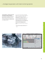
Expandable for complex tasks
– Turning, drilling and milling in one setup (option)
You can use the CNC PILOT 640* to drill
and mill your workpiece on the front face
and lateral surface in one setup. In addition,
the control offers you numerous functions
and well-proven cycles
Drilling, deep-hole drilling, tapping
The CNC PILOT 640 drills, pecks and taps
individual holes with the C or Y axis. Using
parameters you can easily program infeed
reductions for the beginning of drilling or
when drilling completely through the
workpiece.
* Optional. The machine and the CNC PILOT 640 must
be adapted to this function by the machine tool
builder.
Drilling and milling patterns
If bore holes, slots or ICP milling cycles are
located at regular distances on a straight
line or a circular arc, the CNC PILOT greatly
simplifies your work: You can create these
patterns on the front face or lateral surface
with just a few key strokes.
Thread milling
On lathes equipped with a C or Y axis, you
can take advantage of thread-milling,
because the CNC PILOT 640 supports
special thread-milling tools.
Milling slots and simple figures
Slot milling with the CNC PILOT 640 is
very simple. You define the position and
depth of the slot as well as the cutting
values—the milling cycles automatically
take care of the rest.
Even for simple contours such as circles,
rectangles and equilateral polygons, just a
few keystrokes are necessary to determine
the figure and position.
Drilling
Deep-hole drilling
Tapping
Thread milling
Drilling or tapping
20
smart.Turn units and DIN PLUS cycles for drilling
Contour and pocket milling
The CNC PILOT 640’s milling cycles support
both contour and pocket milling. You
determine all the important details, such
as machining direction, milling direction,
approach and departure behavior, infeeds,
etc. The CNC PILOT 640 automatically
compensates for the tool radius.
You can mill the pocket in two stages—first
roughing, and then finishing. The result is
high accuracy and good surface quality.
In smart.Turn and DIN programming, the
CNC PILOT 640 supports various infeed
strategies. You can choose between direct,
reciprocating, or helical infeed, or infeed at
the predrilling position.
Face milling
The face milling cycle machines individual
surfaces, equilateral polygons or a circle—
even off-center.
Engraving cycles
Do you want to “inscribe” your
workpieces? That’s no problem with the
CNC PILOT 640. The smart.Turn units for
engraving only need a few parameters to
engrave characters of any size on a face or
lateral surface, or on the XY or YZ plane.
On the workpiece face you can arrange the
characters on a line or an arc. On the lateral
surface, and when engraving with the Y
axis, you define the angle at which the
characters are to be arranged.
Of course, the engraving cycles are also
available as DIN PLUS cycles.
Deburring
The CNC PILOT 640 supports special units
or DIN PLUS cycles for deburring. You
enjoy the benefit of being able to program
this operation with only a few parameters.
Helical slot milling
The helical-slot milling cycle is useful for
machining lubrication grooves. You specify
all important parameters such as pitch,
cutting in multiple infeeds, etc.
Slot milling
Figure milling (circles, rectangles,
regular polygons)
ICP contour milling
Face milling (single surfaces,
flattening, polygon)
Helical slot milling
smart.Turn units and DIN PLUS cycles for milling
Face and lateral-surface milling
21
Expandable for complex tasks
– Full-surface machining including the C axis and Y axis (option)
The CNC PILOT 640 provides a solution
for any machining task and any machine
configuration: it performs complex
machining tasks with a C or Y axis. It also
controls full-surface cutting on dual-spindle
machines.
And for C-axis, Y-axis, and full-surface
machining you can select from the
DIN PLUS, smart.Turn or Teach-in
programming modes.
C axis or positionable spindle*
For more complex tasks, the CNC PILOT 640
can be expanded to also control a C axis or
positionable spindle and a driven tool. The
driven tool makes it possible to drill offcenter and to tap holes while the spindle is
at rest. The C axis or positionable spindle
permit milling, drilling, and boring on the
face and lateral surface of the workpiece.
These elements can be displayed for
programming and verification in face view
and in the unrolled lateral surface view.
Y axis*
With the Y-axis option of the CNC PILOT 640
you can machine slots or pockets with plane
bottoms and perpendicular slot angles. By
defining the spindle angle, you can determine
the position of the milling contours on the
workpiece. For programming and verification
of these machining sections, the workpiece
is shown in side and face view. The Y axis is
supported in the smart.Turn and DIN
programming feature.
Dual-spindle option
For full-surface lathes, the CNC PILOT 640
provides the following features:
• Opposing spindle with second C axis
• Movable tailstock (W axis)
These features are complemented by
additional functions such as coordinate
transformation, spindle synchronization and
traversing to a stop surface.
Coordinate transformation
Contours of workpiece blanks and finished
parts can be mirrored about the X axis or
shifted relative to the workpiece datum.
* The machine and CNC PILOT 640 must be adapted to
this function by the machine tool builder.
Graphic contour programming for C-axis machining (milling, drilling and
boring)
22
First fixture
Spindle synchronization
Opposing spindles are electronically
coupled and rotate synchronously. This
makes it possible to transfer the workpiece
from one spindle to the other while they
are rotating, thereby saving the time
otherwise spent braking and starting the
spindles. The CNC PILOT 640 detects any
angular offset and compensates it during
subsequent milling on the opposing
spindle.
Traversing to a fixed stop
To ensure that the workpiece is firmly
pressed to the opposite spindle surface,
the control monitors the nominal and actual
positions while the longitudinal axis is
moving and thereby detects the fixed stop.
The CNC PILOT 640 monitors the motor
torque and uses it to reach the
programmed contact force.
Eccentric turning and non-circular
turning*
The CNC PILOT 640 offers convenient
cycles for eccentric turning and for the
manufacture of oval and polygonal parts.
In this case—in addition to the actual
contour machining—traverse movements
of the X and Y axes are superimposed. The
manufacture of cams and non-circular parts
is possible without any additional machine
elements.
* These functions must be implemented in the
machine and control by the machine tool
builder.
S1/C1
S3/C2
S1/C1
W
Full-surface machining: opposing spindle (S3) with C axis (C2) on secondary
axis (W) and driven tool (S2)
Spindle 1 (S1) with C axis (C1) and driven tool (S2)
Machining of the rear face on the opposing spindle after
automatic workpiece transfer
23
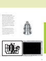
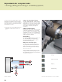
Expandable for complex tasks
– Working in a tilted plane with the B axis (option)
The B axis makes it possible to drill, bore
and mill in oblique planes. At first glance,
programming for such operations seems
very complex and compute-intensive. But
with the CNC PILOT 640 you simply tilt the
coordinate system to the required position
and program machining as usual in the
working plane. The machine will then
execute machining in the tilted working
plane.
The B axis also provides benefits for
turning operations. By tilting the B axis
and rotating the tool you can bring it into
positions that enable you to use a single
tool to machine in the longitudinal and
transverse directions on the main and
opposing spindles. That allows you to
reduce the number of tools needed as
well as do without certain tool changes.
Programming
The usual separation of contour description
and machining on the CNC PILOT 640 also
applies to milling, drilling and boring
operations in a tilted plane.
First you rotate and shift the coordinate
system so that it lies in the tilted plane.
Then you describe the hole pattern or the
milling contour as you would in the YZ
plane. Here you can use the hole pattern
and figure definitions of the CNC PILOT
640. This means that, for linear or circular
patterns and simple figures (circles,
rectangles, regular polygons, etc.), you only
need a few more entries to describe the
pattern or figure in the tilted plane.
Simulation
In the Side View window, the simulation
shows the hole pattern and milling contour
perpendicular to the tilted plane—without
distortion. This ensures simple verification
of programmed hole patterns and milling
contours. You also verify the tool
movements in the Side View window. If
you want to check the machining in the
tilted plane with respect to the rotated
contour or the face, add the Lathe Window
or Front Window. In the position display
(below the simulation window), the CNC
PILOT 640 displays the angle of the tilted
plane and the tilt angle in the B axis. And
do you want to see the active coordinate
system? No problem—with a simple
keystroke the CNC PILOT 640 shows the
current datum and the direction of the
active coordinate system.
Machining in the tilted plane
24
Flexible use of tools*
If your machine is equipped with a B axis,
you can use your tools much more
efficiently than before. On conventional
lathes you need four different tools for
longitudinal and transverse turning on
opposing spindles. With a B axis, you can
do it with a single tool.
You simply tilt the B axis and rotate the
tool to the normal position or for machining
from behind the workpiece—whichever is
required for longitudinal or transverse
turning on the main or opposing spindle. All
you need is a single call: the CNC PILOT 640
calculates the tool lengths, the tool angle
and the other tool data for you.
Tool-use flexibility is increased significantly
when several tools are mounted in one
holder. For example, with a roughing,
finishing and recessing tool you can
perform considerable parts of turning and
recessing operations on a main and
opposing spindle—without changing the
tool. And programming is very easy. You
simply indicate which tooth of the tool to
use and then define the tilting angle and
the tool position. And no more, because
the CNC PILOT 640 already has the rest
position and the data of each tool tooth in
its database.
This type of flexibility lowers the number of
your tools, and you save machining time by
reducing the tool changes.
* The machine and CNC PILOT 640 must be adapted
for this function.
Facing and ...
... longitudinal turning with the same tool ...
... and for several tools on one holder.
25
Powerful Teach-in mode (option)
– Cycles with preprogrammed working steps
Workpiece machining in Teach-in mode
For simple, non-recurring tasks, reworking,
or thread repair, the cycles of the
CNC PILOT 640 simplify your work.
The help graphics illustrate the few entries
needed for the cycles. Before cutting, use
the simulation to assure yourself that the
machining will run as planned.
Thread-recut cycles
Even if the workpiece was unclamped,
you can very easily recut a thread with the
CNC PILOT 640.
Simply clamp the workpiece and position
the threading tool in the middle of a thread.
The CNC PILOT 640 remembers this
position and the spindle angle. When you
position your threading tool in front of your
workpiece and enter the other parameters
of the thread, the CNC PILOT 640 has all
the information it needs to recut the
thread.
Fewer calculations
In Teach-in mode, too, the CNC PILOT 640
automatically calculates the number of cuts
for roughing, recessing, recess turning or
thread cutting, and for pecking it
determines the required number of
infeeds. When turning a taper, you can
enter either the starting point and end
point, or the starting point and the taper
angle—whichever is shown on your
drawing.
Constant availability of tool data
The CNC PILOT 640 uses a tool database.
Tool data, such as cutting radius, tool angle
and point angle only have to be entered
once to find the setting dimensions.
The CNC PILOT 640 saves the data. The
next time you use the tool, you simply
call the tool number. The CNC PILOT 640
automatically adjusts for the correct tool
size. You can immediately work to
dimension.
When turning a contour, the
CNC PILOT 640 automatically
compensates the deviations due
to the cutting-edge radius. This increases
the precision of your workpiece.
Threads, undercuts, parting
26
Single- or multi-start longitudinal,
tapered or API thread
Longitudinal/transverse cutting for simple
contours
Undercuts as per DIN 76,
DIN 509 E or DIN 509 F
Longitudinal/transverse cutting with
plunging
Undercut form H, form K or form U
Longitudinal/transverse ICP cutting for
any contours
Parting
Longitudinal/transverse ICP contour
parallel cutting
Area clearance—cutting and finishing
Technology data as default values
The CNC PILOT 640 saves the cutting data
according to the criteria of workpiece
material, tool material, and machining
mode. As you have already entered the
cutting material in the tool definition, you
need only enter the material of your
workpiece. This provides the cycle with all
data required for setting default values for
the cutting data.
Datums
You can define the workpiece datum by
touching the workpiece with the tool or by
entering the datum coordinates.
Protective zone for the spindle
For every tool movement in the negative
Z direction, the CNC PILOT 640 checks
whether the programmed protective zone
would be violated. If so, it stops the
movement and responds with an error
message.
Teach-in with contour follow-up
You can activate “contour follow-up” by
defining a workpiece blank. This ensures
that every Teach-in cycle knows the current
workpiece blank, so that air cuts are
avoided. This is possible with any kind
of turning operation.
Approach the tool-change point once and
store this position. Then a simple cycle call
suffices to return to the tool change point.
Radial/axial recessing for simple contours
Longitudinal/transverse recess turning
for simple contours
Radial/axial ICP recessing for any
contours
Longitudinal/transverse ICP recess
turning for any contours
Recessing and recess turning—cutting and finishing
27
Fast availability of tool data and cutting data
– The tool database and technology database of the CNC PILOT 640
Tool database
The CNC PILOT 640 can store 250 tools
in the standard tool database. The tool
database can be expanded to 999 tools
(option).
The CNC PILOT 640 differentiates between
various types of turning, drilling and milling
tools. The required data input varies
depending on the tool type. In this way you
can be sure that all important parameters
are specified in spite of reduced data input.
The tool data are entered through prompts
in which you enter parameters such as
cutting-edge radius, tool angle and point
angle, cutting material and the tool
description. The input parameters are
illustrated in context-sensitive help
graphics.
Tool list
The CNC PILOT 640 shows all tools in a
clearly laid out tool list. Various sorting
criteria help you to quickly find the desired
tool.
This list not only gives you a good overview
of your tools—it is also the basis for
transferring tool data during manual
machining and when you’re creating NC
programs.
Tool management in the tool list
28
Wear compensation
The CNC PILOT 640 offers a simple and
straightforward function for compensating
tool wear in both the X and the Z axes. You
can enter the compensation values at any
time, even during machining or after
machining the workpiece.
Tool measurement
The CNC PILOT 640 offers various
possibilities for the measurement of tools
directly on the machine:
• By touching the workpiece
• By means of an optical gauge* (option):
the tool is manually traversed to the
cross hairs of the measuring optics, and
the value is saved with a keystroke.
• Through a tool touch probe* (option): the
tool moves in measuring direction. The
tool setting dimension is ascertained and
adopted when the tool touch probe
releases a trigger signal, e.g. the TT 160
touch trigger probe with cuboid probe
contact.
You can determine the tool data particularly
easily, reliably and precisely during tool
measurement with an optical gauge or tool
touch probe.
* The machine and CNC PILOT 640 must be adapted to
this function by the machine tool builder.
Tool editor
Turret assignment
You can view your machine’s programmed
turret assignment with all important tool
parameters at any time.
If you want to change the tool assignment
or the tools in the turret, you can additionally
display the entries of the tool database in
the lower window. Now you need only
select the desired turret pocket and choose
the correct tool from the database. You
can transfer the tool data to the turret
assignment entry with a simple keystroke.
Tool life monitoring (option)
With smart.Turn and DIN PLUS programs,
in addition to the simple tool life monitoring
feature you can also use the “tool life
monitoring with sister tool” option. The
CNC PILOT 640 then automatically inserts
a sister tool as soon as the active tool is
used up. When the last tool of the
replacement chain is used up, the
CNC PILOT 640 stops program execution.
Tool selection for turret assignment
Technology data (option)
With the CNC PILOT 640 you need enter
the cutting data only once. The control
saves the cutting data according to the
criteria of workpiece material, cutting
material, and machining mode. Thanks to
this three-dimensional table, the control
always knows the correct feed rate and the
correct cutting speed.
The CNC PILOT 640 determines the machining mode from the Teach-in cycle or the
unit. The cutting material is entered during
the tool description. You need only define
the workpiece material at the beginning
of the cycle program or the smart.Turn
program, and the CNC PILOT 640 will
propose the correct values for your
machining operation. You can use the
suggested cutting parameters or adjust
them if required.
In its standard version, you can store the
cutting data for 9 workpiece-material/toolmaterial combinations in the technology
database of the CNC PILOT 640. It can be
expanded to 62 combinations (option).
Each workpiece-material/tool-material
combination includes the cutting speed,
the main and secondary feed rates, and
the infeed for 16 machining modes.
Input of cutting values in the technology editor
29
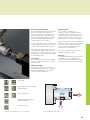
Open for communication
– Fast data transfer with the CNC PILOT 640
The networked CNC PILOT 640
The CNC PILOT 640 can be integrated
into networks and connected with PCs,
programming stations and other data
storage devices. Even in its standard
version, the CNC PILOT 640 features a
latest generation Gigabit Ethernet interface.
The CNC PILOT 640 communicates with
NFS servers and Windows networks in
TCP/IP protocol without needing additional
software. The fast data transfer at rates of
up to 1000 Mbit/s guarantee very short
transfer times.
USB interface
The CNC PILOT 640 supports standard
memory media with USB interface. Using
USB memory media (such as memory
sticks), you can quickly and easily exchange
DXF contours, ICP contour descriptions,
NC programs, tool parameters, etc.,
between systems that are not connected
to each other.
All programs at a glance
After entering the path of the partner
terminal, your own CNC PILOT 640
programs will be listed on the left side of
the screen, and your partner’s programs
are on the right side. Now select the
programs that you want to transfer and
press the send or receive button. The data
is transferred reliably and almost
instantaneously.
Transferring programs
An especially easy and convenient method
of transferring data is to integrate the
systems into your company network.
When transferring NC programs, the
CNC PILOT 640 even considers the files
associated with the cycle program, smart.
Turn program or DIN PLUS program, such
as contour descriptions, DIN macros or
subprograms.
Exchanging tool data
Once you have acquired tool data, you
may also transfer them. That is not only
important for data backup: it also helps you
when using the PC programming station
DataPilot. The benefits: no redundant data
acquisition; your files are always up to date.
Programs for data transfer
With the aid of the free PC software
TNCremo from HEIDENHAIN and an
Ethernet or other data interface you can
• transfer remotely stored part programs
and tool tables in both directions and
• make backups.
With the powerful TNCremoPlus PC
software you can also transfer the screen
contents of the control to your PC using
the live-screen function.
Company network
CAD/CAM system
DataPilot CP 640
Ethernet interface
iTNC 530
Ethernet interface
Data transfer on the control
TNC 320
Ethernet interface
CNC PILOT 640
Ethernet interface
30
– Display various file formats on the control screen
The new integrated PDF viewer enables
the user to open PDF files directly on the
control. The PDF format is a widely used
data format that can be generated out of a
great variety of applications. This enables
you to easily view work instructions,
drawings or other information in the
CNC PILOT 640.
The integrated browser now lets you
connect the CNC PILOT 640 to the Internet
and access it directly from the control.
The following further file formats can also
be opened directly on the CNC PILOT 640
with corresponding editors, and
sometimes edited.
• Text files ending with .txt or .ini
• Graphic files ending with .gif, .bmp, .jpg,
.png
• Table files ending with .xls or .csv
• HTML files
An operating panel with an integrated
touchpad or an external USB pointing
device is required for operation.
31
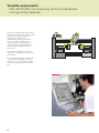
Open for communication
– The DataPilot CP 640 programming station
DataPilot CP 640 is the PC programming
station for the CNC PILOT 640 and the
organizing system for the workshop and
design office.
That is why DataPilot CP 640 is the ideal
supplement to the CNC PILOT 640 for
program creation, archiving, and apprentice
and advanced training.
Creating programs
Programming, testing and optimizing
smart.Turn and DIN PLUS programs with
DataPilot on your PC substantially reduce
idle machine times. You do not need to
adjust your way of thinking, since you
program and test with DataPilot in exactly
the same way as on the lathe. DataPilot
has the same software as the control. This
ensures that a program created with
DataPilot can be run on the machine
immediately.
Archiving programs
Even though the CNC PILOT 640 has a
large memory capacity, you should also
back up your programs on an external
system. The CNC PILOT 640 features a
USB and an Ethernet interface. This enables
you to integrate the CNC PILOT 640 into
your existing network or to connect the
DataPilot PC directly to the control.
Convenient program transfer functions
support both programming as well as
archiving on the DataPilot PC.
Training with DataPilot CP 640
Because DataPilot CP 640 is based on the
same software as the CNC PILOT 640, it is
ideally suited for apprentice and advanced
training. Programming and program testing
on the DataPilot PC function exactly the
same as they do on the machine. DataPilot
even simulates setup functions such as
defining the workpiece datum, measuring
tools or running individual cycles or
smart.Turn or DIN PLUS programs. This
gives the trainee the experience needed to
enable him to safely operate the machine
later.
System requirements
DataPilot runs on PCs with the Windows
XP, Windows Vista, Windows 7 or Windows
8 operating systems.
Trainer
Printer
Trainees
32
Machine tool
– Fast availability of all information
Do you have questions on a programming
step, but your User’s Manual is not at
hand? No problem: The CNC PILOT 640
numerical control and DataPilot CP 640
programming station feature TURNguide, a
convenient help system that can show the
user documentation in a separate window.
You activate TURNguide simply by pressing
the Info key on the keyboard.
TURNguide usually displays the information
in the immediate context of the element in
question (context-sensitive help). This
means that you immediately receive the
relevant information. The function is
particularly helpful for the programming of
cycles. The respective operating method is
explained in detail in an open dialog
window when you press the Info key.
You can download the documentation
in the desired language from the
HEIDENHAIN homepage into the
corresponding language directory on
your control.
The following manuals are available in the
help system:
• CNC PILOT 640 User’s Manual
• User’s Manual for smart.Turn and
DIN programming
• User’s Manual for the CP 640 DataPilot
(only included in the programming
station)
… or at the programming station.
TURNguide integrated in the control, e.g. on the CNC PILOT 640 ...
33
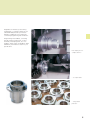
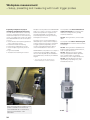
Workpiece measurement
– Setup, presetting and measuring with touch trigger probes
Inspecting workpieces for proper
machining and dimensional accuracy
The CNC PILOT 640 features measuring
cycles for checking the geometry of the
machined workpieces. For the measuring
cycles, you simply insert a 3-D touch probe
from HEIDENHAIN into the turret in place
of a tool:
• Check whether all machining operations
were conducted correctly
• Determine infeeds for finishing
• Detect and compensate tool wear
• Check workpiece geometry and sort
parts
• Log measured data
• Ascertain the machining error trend
Workpiece touch probes from HEIDENHAIN
help you to reduce costs in the workshop
and in series production: Together with
the CNC PILOT 640, touch probes can
automatically perform setup, measuring
and inspection functions.
The stylus of a TS touch trigger probe is
deflected upon contact with a workpiece
surface. At that moment the TS generates
a trigger signal that, depending on the
model, is transmitted either by cable or
over an infrared beam to the control.
HEIDENHAIN touch probes* for workpiece
measurement are available in different
versions. The ruby ball tips are available in
several diameters, and the styli in different
lengths.
* The touch probes must be interfaced to the
CNC PILOT 640 by the machine tool builder.
More information about workpiece touch
probes is available on the Internet at
www.heidenhain.de or in the Product
Overview Touch Probes – New
Generation.
34
Touch probes with cable connection for
signal transmission for machines with
manual tool change and for grinding
machines and lathes:
TS 260 – New generation, axial or radial
cable
Touch probe with radio or infrared signal
transmission for machines with automatic
tool change:
TS 460 – New generation standard touch
probe for radio and infrared transmission,
with compact dimensions
TS 444 – Battery-free voltage supply
through integrated air turbine generator
from compressed air, for infrared
transmission, with compact dimensions
TS 740 – High probing accuracy and
repeatability, low probing force, with
infrared transmission
TS 460
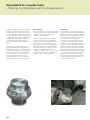
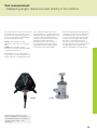
Tool measurement
– Measuring length, radius and wear directly in the machine
Exact measurement of the tool dimensions
is a decisive factor for ensuring a consistently high level of production quality. The
TT tool touch probes from HEIDENHAIN
are intended for this purpose.
TT 160 – New generation, signal
transmission to the NC over connecting
cable
TT 460– New generation, signal
transmission over radio and infrared beam
to transmitter/receiver unit
The TT 160 and TT 460 are 3-D touch
trigger probes for tool measurement and
inspection. The disk-shaped probe contact
of the TT is deflected during physical
probing of a tool. At that moment the TT
generates a trigger signal that is
transmitted to the control, where it is
processed further. The trigger signal is
generated through a wear-free optical
switch that ensures high reliability.
With their rugged design and high degree
of protection, these tool touch probes can
be installed directly within the machine
tool’s work envelope and make it possible
to calibrate the tool right in the machine.
This way you can determine the tool
dimensions quickly, easily and, above all,
very precisely. The TT tool touch probes are
the ideal supplement to improve the
efficiency and quality of your production.
The SE 660 is a common transmitter/
receiver unit for tool and workpiece touch
probes with radio or infrared transmission.
SE 660
TT 160
More information about tool touch
probes is available on the Internet at
www.heidenhain.de or in the Product
Overview Touch Probes – New
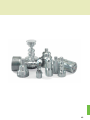
Generation.
35
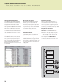
Overview
– User functions
Configuration
Option
Default
User functions
•
0-6
55+0-6
70+0-6
54+0-6
94+0-6
132+0-6
•
Operating modes
Manual Operation
•
•
11
Teach-In mode
8
Program Run
Programming
Cycle programming
Sequential linking of fixed cycles, where each cycle is run immediately after input, or is
graphically simulated and subsequently saved
9
8
17
17
17
Workpiece datum setting
Defining the tool-change point
Definition of protection zone
Defining machine dimensions
Manual programs
Tool measurement by touching the workpiece
Tool measurement with a TT tool touch probe
Tool measurement with an optical gauge
Workpiece measurement with a TS workpiece touch probe
•
•
•
•
•
•
8
8
8
8
8
8
8
8
8+55
8+55
8+55
8+55
8+55
8+55
8
8
8
8+9
36
Manual slide movement through axis-direction keys, intermediate switch or electronic
handwheels
Graphic support for entering and running cycles without saving the machining steps in
alternation with manual machine operation
Thread reworking (thread repair in a second workpiece setup)
Both in single-block and full-sequence modes
DIN PLUS programs
smart.Turn programs
Cycle programs
•
Setup Functions
Basic version: X and Z axis, spindle
Driven tool and auxiliary axes (U, V, W)
C axis and driven tool
Y axis
B axis
Parallel axes (U, V, W)
Opposing spindle
Digital current and speed control
Turning cycles for simple and complex contours, and contours described with ICP
Contour-parallel turning cycles
Recessing cycles for simple or complex contours, as well as contours defined with ICP
Repetitions with recessing cycles
Recess turning cycles for simple and complex contours, and contours described with ICP
Undercut and parting cycles
Engraving cycles
Threading cycles for single or multi-start longitudinal, taper or API threads, threads with
variable pitch
Cycles for axial and radial drilling, pecking and tapping operations with the C axis
Thread milling with the C axis
Axial and radial milling cycles for slots, figures, single surfaces and polygons as well as for
complex contours defined with ICP for machining with the C axis
Helical slot milling (multi-start) with the C axis
Deburring of ICP contours
Linear and circular patterns for drilling, boring and milling operations with the C axis
Context-sensitive help graphics
Transfer of cutting values from technology database
Use of DIN macros in cycle programs
Conversion of cycle programs to smart.Turn programs
Option
Default
User functions
Interactive contour
programming (ICP)
Contour definition with linear and circular contour elements
Immediate display of entered contour elements
Calculation of missing coordinates, intersections, etc.
Graphic display of all solutions for selection by the user if more than one solution is possible
Chamfers, rounding arcs and undercuts available as form elements
Input of form elements immediately during contour creation or by superimposition later
Changes to existing contours can be programmed
Machining attributes available for individual contour elements
C-axis machining on face and lateral surface:
Description of individual holes and hole patterns (only in smart.Turn)
Description of figures and figure patterns for milling (only in smart.Turn)
Creation of freely definable milling contours
9+70 Y-axis machining on the XY and ZY planes (only in smart.Turn):
Description of individual holes and hole patterns
Description of figures and figure patterns for milling
Creation of freely definable milling contours
8/9+55+ Programming of the rear face for full-surface machining with the C and Y axes
70+132
8/9+42 DXF import: Import of contours for lathe and milling operations
smart.Turn
programming
The basis is the unit, which is the complete description of a machining block (geometry,
technology and cycle data)
Dialog boxes divided into overview and detail forms
9
Fast navigation between the fillable forms and input groups via the "smart" keys
9
Context-sensitive help graphics
9
Start unit with global settings
9
Transfer of global values from the start unit
9
Transfer of cutting values from technology database
9
Units for all turning and recessing operations for simple contours and ICP contours
9
9+55/70 Units for boring, drilling and milling operations with the C or Y axis for simple holes, milling
contours and drilling and milling patterns as well as those programmed with ICP
9+55 Special units for activating/deactivating the C axis, subroutines and section repeats
9+55/70 Verification graphics for blank and finished part and for C and Y axis contours
Turret assignment and other setup information in the smart.Turn program
9
Parallel programming
9
Parallel simulation
9
TURN PLUS
8/9
8/9
8/9
8/9
8/9
8/9
8/9
8/9
8/9+55
9
63
Automatic working plan generation with:
• Automatic tool selection
• Automatic turret assignment
• Automatic calculation of cutting data
• Automatic generation of the machining sequence in all working planes, also for C-axis
machining (with option 55) and Y-axis machining (with option 70)
• Automatic cutting limitation through chucking equipment
• Automatic generation of work blocks for rechucking during full-surface machining
• Automatic generation of work blocks for rear-face machining (with option 132)
37
Overview
– User functions (continued)
DIN PLUS
programming
Program verification
graphics
Option
Default
User functions
•
•
•
•
Programming in DIN 66025 format
Extended command format (IF ... THEN ... ELSE ...)
Simplified geometry programming (calculation of missing data)
Powerful fixed cycles for area clearance, recessing, recess turning and thread machining
Powerful fixed cycles for boring, drilling and milling with the C axis
55
Powerful fixed cycles for boring, drilling and milling with the Y axis
70
•
Subprograms
Technology functions for full-surface machining:
•
– Moving to a fixed stop
•
– Parting control
– Spindle synchronization
131/132
– Converting and mirroring
132
•
– Mechatronic tailstock
•
Programming with variables
Contour description with ICP
8/9
•
Program verification graphics for workpiece blank and finished part
•
Turret assignment and other setup information in the DIN PLUS program
Conversion of smart.Turn units into DIN PLUS command sequences
9
•
Parallel programming
•
Parallel simulation
•
•
•
55
•
54
•
•
132
•
•
B axis machining
54
•
54
Eccentric machining
Machining time analysis
Monitoring function
38
135
135
Graphic simulation of the cycle process, or of the cycle, smart.Turn or DIN PLUS program
Display of the tool paths as pencil-trace or cutting-path graphics, special identification of the
rapid traverse paths
Machining simulation (2-D material-removal graphic)
Side or face view, or 2-D view of cylindrical surface for verification of C-axis machining
Display of programmed contours
View of the tilted plane (B-axis machining)
View of face and YZ plane for verification of Y-axis machining
Three-dimensional display of the workpiece blank and finished part
Simulation of mirrored contours for rear-face machining
Shifting and magnifying functions
Block scan in the simulation
Machining with the B axis
Tilting the working plane
Rotating the machining position of the tool
Cycles for eccentric turning and for the manufacture of oval and polygonal contours
Superimpositioning of traverse movements of the X and Y axes synchronous to the rotational
motion of the spindle
Calculation of machining times and idle times
Consideration of switching commands triggered by the CNC
Representation of time per individual cycle or per tool change
•
•
•
151
Load monitoring—detecting tool wear and breakage during machining
Tool database
Option
Default
User functions
•
10
•
•
•
•
•
•
10
•
•
Technology database
8/9
8/9
8/9
8/9
10
Conversational languages •
For 250 tools
For 999 tools
Tool description can be entered for every tool
Automatic inspection of tool-tip position with respect to the contour
Compensation of tool-tip position in the X/Y/Z plane
High-precision correction via handwheel, capturing compensation values in the tool table
Automatic tool-tip and cutter radius compensation
Tool monitoring for lifetime of the insert (tool tip) or the number of workpieces produced
Tool monitoring with automatic tool change after expiration tool life
Management of multipoint tools (multiple inserts or reference points)
Support of quick-change systems
Access to cutting data after definition of workpiece material, cutting material and machining
mode. The CNC PILOT 640 distinguishes between 16 machining modes. Each workpiecematerial/tool-material combination includes the cutting speed, the main and secondary feed
rates, and the infeed for 16 machining modes.
Automatic determination of the machining modes from the cycle or the machining unit
The cutting data are entered in the cycle or in the unit as default values.
9 workpiece-material/tool-material combinations (144 entries)
62 workpiece-material/tool-material combinations (992 entries)
English, German, Czech, French, Italian, Spanish, Portuguese, Dutch, Swedish, Danish,
Finnish, Norwegian, Slovenian, Slovak, Polish, Hungarian, Russian (Cyrillic), Romanian, Turkish,
Chinese (traditional and simplified), Korean
39
Overview
– Options
Option
number
Option
As of NC
software
688946688947-
ID
Remark
0
1
2
3
4
5
6
7
Additional Axis
01
01
01
01
01
01
01
03
354540-01
353904-01
353905-01
367867-01
367868-01
370291-01
307292-01
370293-01
Additional control loops 1 to 8
8
Software option 1
Teach-in
01
632226-01
Cycle programming
• Contour description with ICP
• Cycle programming
• Technology database with 9 workpiece-material/tool-material
combinations
9
Software option 2
smart.Turn
01
632227-01
smart.Turn
• Contour description with ICP
• Programming with smart.Turn
• Technology database with 9 workpiece-material/tool-material
combinations
10
Software option 3
Tools and technology
01
632228-01
Tools and technology
• Tool database expanded to 999 entries
• Technology database expanded to 62 workpiece-material/tool-material
combinations
• Tool life monitoring with exchange tools
11
Software option 4
Thread recutting
01
632229-01
Thread
• Thread recutting
• Handwheel superimposition during thread cutting
17
Touch probe functions
01
632230-01
Tool measurement and workpiece measurement
• Determining tool-setting dimensions with a tool touch probe
• Determining tool-setting dimensions with an optical gauge
• Automatic workpiece measurement with a workpiece touch probe
18
HEIDENHAIN DNC
01
526451-01
Communication with external PC applications over COM component
24
Gantry axes
01
634621-01
Gantry axes in master-slave torque control
42
DXF import
01
632231-01
DXF import Import of DXF contours
46
Python OEM process
01
579650-01
Python application on the CNC PILOT 640
49
Double-speed axes
01
632223-01
Short control-loop cycle times for direct drives
54
B-axis machining
01
825742-01
B axis: Tilting the working plane, rotating the machining position of the
tool
55
C-axis machining
01
633944-01
C-axis machining
63
TURN PLUS
01
825743-01
TURN PLUS: Automatic generation of smart.Turn programs
70
Y-axis machining
01
661881-01
Y-axis machining
77
4 additional axes
03
634613-01
4 additional control loops
78
8 additional axes
03
634614-01
8 additional control loops
40
– Accessories
Option
number
Option
As of NC
software
688946688947-
ID
Remark
94
Parallel axes
01
679676-01
Support of parallel axes (U, V, W)
Combined display of principal axes and secondary axes
131
Spindle synchronism
01
806270-01
Synchronization (of two or more spindles)
132
Opposing spindle
01
806275-01
Opposing spindle (spindle synchronism, rear-face machining)
135
Synchronizing
functions
03
1085731-01 Expanded synchronization of axes and spindles
143
Load Adapt. Control
Control
01
800545-01
LAC: Dynamic adaptation of the control parameters
151
Load monitoring
03
1111843-01
Monitoring of the tool load
Accessories
Electronic handwheels
One portable HR 510 serial handwheel
Tool measurement
3-D touch trigger probes:
• TT 160 with a cuboid probe contact and cable connection
• TT 460 with a cuboid probe contact and radio or infrared transmission
Workpiece measurement
•
•
•
•
DataPilot CP 640, MP 620
Control software for PCs for programming, archiving, and training for the CNC PILOT 640
• Full version with license for single station or multiple stations
• Demo version (free of charge)
Software for PCs
• TeleService: Software for remote diagnostics, monitoring, and operation
• TNCremo: Software for data transfer—free of charge
• TNCremoPlus: Software for data transfer with live-screen function
TS 260: Touch trigger probe with cable connection or
TS 460: Touch trigger probe with radio or infrared transmission or
TS 444: Touch trigger probe with infrared transmission or
TS 740: Touch trigger probe with infrared transmission
41
Overview
– Specifications
Specifications
Components
MC main computer with TFT color flat panel display (19-inch or 15-inch), or
MC main computer with integrated TFT color flat panel display (15-inch)
CC, UEC or UMC controller units
TE operating panel (19-inch or 15 inch) with
– Integrated machine operating panel
– Rapid-traverse override, feed-rate override and spindle speed override potentiometer
– Electronic handwheel
Operating system
HEROS 5 real-time operating system for machine control
NC program memory
1.8 GB (on compact flash memory card CFR)
Input resolution and display step
X axis: 0.5 µm, diameter: 1 µm
U, V, W, Y, Z axis: 1 µm
B, C1/C2 axis: 0.001°
Interpolation
Straight line: in 2 principal axes (max. ±100 m), optional in 3 principal axes
Circle: in 2 axes (radius max. 999 m), optional additional linear interpolation of the third axis
C1/C2 axis: interpolation of X and Z linear axes with the C1/C2 axis (option)
B axis: 5-axis interpolation between X, Z, Y, B, and C axes (option)
Feed rate
mm/min or mm/revolution
Constant surface speed
Max. feed rate (60 000/pole pairs × ball screw pitch) at fPWM = 5000 Hz
Spindle
Maximum 60 000 rpm (with 2 pole pairs)
Axis feedback control
Integrated digital drive control for synchronous and asynchronous motors
Position loop resolution: Signal period of the position encoder/1024
Cycle time of position controller: 0.2 ms
Cycle time of speed controller: 0.2 ms
Cycle time of current controller: minimum 0.05 ms
Error compensation
Linear and nonlinear axis error, backlash, reversal peaks during circular movements
Static friction
Data interfaces
Gigabit Ethernet interface 1000BASE-T
5 x USB (1 x front USB 2.0; 4 x rear USB 3.0)
Diagnostics
Fast and simple troubleshooting through integrated diagnostic aids
Ambient temperature
Operation: In electrical cabinet: 5 °C to 40 °C
In operating panel: 0 °C to 50 °C
Storage: –20 °C to 60 °C
42
43
DR. JOHANNES HEIDENHAIN GmbH
Dr.-Johannes-Heidenhain-Straße 5
83301 Traunreut, Germany
{ +49 8669 31-0
| +49 8669 32-5061
E-mail: [email protected]
DE
HEIDENHAIN Vertrieb Deutschland
83301 Traunreut, Deutschland
08669 31-3132
08669 32-3132
E-Mail: [email protected]
ES
FARRESA ELECTRONICA S.A.
08028 Barcelona, Spain
www.farresa.es
PL
APS
02-384 Warszawa, Poland
www.heidenhain.pl
FI
PT
HEIDENHAIN Technisches Büro Nord
12681 Berlin, Deutschland
030 54705-240
HEIDENHAIN Scandinavia AB
01740 Vantaa, Finland
www.heidenhain.fi
FARRESA ELECTRÓNICA, LDA.
4470 - 177 Maia, Portugal
www.farresa.pt
FR
RO
HEIDENHAIN Technisches Büro Mitte
07751 Jena, Deutschland
03641 4728-250
HEIDENHAIN FRANCE sarl
92310 Sèvres, France
www.heidenhain.fr
HEIDENHAIN Reprezentanţă Romania
Braşov, 500407, Romania
www.heidenhain.ro
GB
HEIDENHAIN (G.B.) Limited
Burgess Hill RH15 9RD, United Kingdom
www.heidenhain.co.uk
RS
Serbia BG
RU
MB Milionis Vassilis
17341 Athens, Greece
www.heidenhain.gr
OOO HEIDENHAIN
115172 Moscow, Russia
www.heidenhain.ru
SE
HEIDENHAIN LTD
Kowloon, Hong Kong
E-mail: [email protected]
HEIDENHAIN Scandinavia AB
12739 Skärholmen, Sweden
www.heidenhain.se
SG
HEIDENHAIN PACIFIC PTE LTD.
Singapore 408593
www.heidenhain.com.sg
HEIDENHAIN Technisches Büro West
44379 Dortmund, Deutschland
0231 618083-0
HEIDENHAIN Technisches Büro Südwest
70771 Leinfelden-Echterdingen, Deutschland
0711 993395-0
HEIDENHAIN Technisches Büro Südost
83301 Traunreut, Deutschland
08669 31-1345
AR
AT
AU
GR
HK
HR
Croatia SL
HU
SK
NAKASE SRL.
B1653AOX Villa Ballester, Argentina
www.heidenhain.com.ar
HEIDENHAIN Kereskedelmi Képviselet
1239 Budapest, Hungary
www.heidenhain.hu
KOPRETINA TN s.r.o.
91101 Trencin, Slovakia
www.kopretina.sk
ID
SL
HEIDENHAIN Techn. Büro Österreich
83301 Traunreut, Germany
www.heidenhain.de
PT Servitama Era Toolsindo
Jakarta 13930, Indonesia
E-mail: [email protected]
NAVO d.o.o.
2000 Maribor, Slovenia
www.heidenhain.si
IL
TH
FCR Motion Technology Pty. Ltd
Laverton North 3026, Australia
E-mail: [email protected]
NEUMO VARGUS MARKETING LTD.
Tel Aviv 61570, Israel
E-mail: [email protected]
HEIDENHAIN (THAILAND) LTD
Bangkok 10250, Thailand
www.heidenhain.co.th
IN
HEIDENHAIN Optics & Electronics
India Private Limited
Chetpet, Chennai 600 031, India
www.heidenhain.in
TR
IT
HEIDENHAIN ITALIANA S.r.l.
20128 Milano, Italy
www.heidenhain.it
TW
HEIDENHAIN Co., Ltd.
Taichung 40768, Taiwan R.O.C.
www.heidenhain.com.tw
JP
HEIDENHAIN K.K.
Tokyo 102-0083, Japan
www.heidenhain.co.jp
UA
Gertner Service GmbH Büro Kiev
01133 Kiev, Ukraine
www.heidenhain.ua
KR
HEIDENHAIN Korea LTD.
Gasan-Dong, Seoul, Korea 153-782
www.heidenhain.co.kr
US
HEIDENHAIN CORPORATION
Schaumburg, IL 60173-5337, USA
www.heidenhain.com
MX
HEIDENHAIN CORPORATION MEXICO
20290 Aguascalientes, AGS., Mexico
E-mail: [email protected]
VE
Maquinaria Diekmann S.A.
Caracas, 1040-A, Venezuela
E-mail: [email protected]
MY
ISOSERVE SDN. BHD.
43200 Balakong, Selangor
E-mail: [email protected]
VN
AMS Co. Ltd
HCM City, Vietnam
E-mail: [email protected]
ZA
MAFEMA SALES SERVICES C.C.
Midrand 1685, South Africa
www.heidenhain.co.za
BE
HEIDENHAIN NV/SA
1760 Roosdaal, Belgium
www.heidenhain.be
BG
ESD Bulgaria Ltd.
Sofia 1172, Bulgaria
www.esd.bg
BR
DIADUR Indústria e Comércio Ltda.
04763-070 – São Paulo – SP, Brazil
www.heidenhain.com.br
BY
GERTNER Service GmbH
220026 Minsk, Belarus
www.heidenhain.by
CA
HEIDENHAIN CORPORATION
Mississauga, OntarioL5T2N2, Canada
www.heidenhain.com
CH
HEIDENHAIN (SCHWEIZ) AG
8603 Schwerzenbach, Switzerland
www.heidenhain.ch
NL
CN
DR. JOHANNES HEIDENHAIN
(CHINA) Co., Ltd.
Beijing 101312, China
www.heidenhain.com.cn
HEIDENHAIN NEDERLAND B.V.
6716 BM Ede, Netherlands
www.heidenhain.nl
NO
HEIDENHAIN s.r.o.
102 00 Praha 10, Czech Republic
www.heidenhain.cz
HEIDENHAIN Scandinavia AB
7300 Orkanger, Norway
www.heidenhain.no
PH
Machinebanks` Corporation
Quezon City, Philippines 1113
E-mail: [email protected]
CZ
DK
TP TEKNIK A/S
2670 Greve, Denmark
www.tp-gruppen.dk
895949-25 · 5 · 9/2015 · F&W · Printed in Germany
·
T&M Mühendislik San. ve Tic. LTD. ŞTI.
34775 Y. Dudullu –
Ümraniye-Istanbul, Turkey
www.heidenhain.com.tr
Zum Abheften hier falzen! / Fold here for filing!
Vollständige und weitere Adressen siehe www.heidenhain.de
For complete and further addresses see www.heidenhain.de
www.heidenhain.de