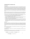
1
Hani S. Mitri
July 2002
R-308
ÉTUDES ET
RECHERCHES
Design and Development
of a New Rockbolt Load
Measuring Device
REPORT
(The Institut de recherche Robert-Sauvé
en santé et en sécurité du travail
(IRSST) Occupational Health and Safety
Research Institute Robert-Sauvé) is a
scientific research agency committed to
the identification and elimination at the
source of occupational hazards,
and the rehabilitation of workers who
have suffered occupational injuries.
With funding provided by the
Commission pour la santé et la sécurité
au travail du Québec (CSST, Québec
Occupational Health and Safety
Commission), the IRSST conducts,
funds and contracts research aimed at
reducing the human and financial costs
of occupational accidents and diseases.
For up-to-date information on research
conducted or funded by the IRSST,
subscribe to Prévention au travail, the
free magazine published in conjunction
with the CSST. 1-877-221-7046
Reports describing the results of
Institute research are available upon
request from the Communications
Division or free of charge on the
Institute’s Web Site..
Legal Deposit
Bibliothèque nationale du Québec
2002
IRSST - Direction des communications
505,West De Maisonneuve Blvd,
Montreal (Quebec)
H3A 3C2
Telephone : (514) 288-1551
Fax: (514) 288-7636
[email protected]
www.irsst.qc.ca
© Institut de recherche Robert-Sauvé
en santé et en sécurité du travail
July 2002.
Hani S. Mitri,
Department of Mining, Metals and Materials Engineering, McGill University
ÉTUDES ET
RECHERCHES
Design and Development
of a New Rockbolt Load
Measuring Device
REPORT
Clic Research
www.irsst.qc.ca
This publication is available free
of charge on the Web site.
This study was financed by the IRSST. The conclusions and recommendations are those of the author.
TABLE OF CONTENTS
Acknowledgement ..........................................................................................................................II
Summary ......................................................................................................................................... 1
1.
INTRODUCTION................................................................................................................... 2
2.
REVIEW OF ROCKBOLT LOAD MONITORING TECHNOLOGIES .............................. 2
3.
OBJECTIVES ......................................................................................................................... 6
4.
DESCRIPTION OF TEST RIG .............................................................................................. 6
5.
PRINCIPLES BEHIND THE LOAD MEASUREMENT TECHNIQUE .............................. 9
6.
DESIGN OPTIMIZATION FOR THE MINING ENVIRONMENT TO OVERCOME THE
EFFECTS OF CORROSION, TEMPERATURE VARIATION AND SEVERE
HANDLING.......................................................................................................................... 14
7.
FIRST PILOT IN SITU PROGRAM.................................................................................... 20
8.
FURTHER MODIFICATION AND OPTIMIZATION OF THE SAFEBOLT SYSTEM IN
LIGHT OF THE IN SITU PILOT TESTS ............................................................................ 30
9.
SECOND PILOT IN SITU PROGRAM............................................................................... 33
10. CONCLUSIONS ................................................................................................................... 41
APPENDIX A: SAFEBOLT USER’S MANUAL ....................................................................... 43
i
Acknowledgement
This work was made possible thanks to the financial support of l’Institut de recherche RobertSauvé en santé et en sécurité du travail (IRSST). Their financial support is gratefully
acknowledged. I would like to acknowledge with many thanks the help of my research group:
Joseph Marwan, Research Associate in Mining Engineering at McGill, for his uninterrupted
devotion and hard work on this project, Wilfrid Comeau, Adjunct Professor, who was
instrumental in the design and construction of the test rig, and James Davison, Research
Assistant, who helped in many aspects of the project and notably the design and assembly of the
readout unit.
The field demonstration and validation of the SAFEBOLT technology in underground mines was
made possible thanks to the participation of Quebec underground mines, namely Bousquet,
Doyon and Niobec. In particular, I would like to thank Mr. Paul Gauthier and Mr. Alain Mercier
from the Bousquet mine, Mr. André Harvey and Mr. Robert Marchand from the Doyon mine,
and Mr. Martin Lanctôt and Mr. Steve Thivièrge from the Niobec mine. I very much appreciate
the help and cooperation of the underground operators during the field visits.
Hani Mitri
iii
Summary
A new technology for the measurement of axial load on rockbolts and rebars in underground
mines has been designed and developed in the laboratory. The technology is known as
SAFEBOLT (Stress And Force Evaluator in BOLTS). The SAFEBOLT system consists of three
components: 1) the SAFEBOLT device installed in the bolt head, 2) a readout unit, and 3) a
connecting cable. A special test rig was constructed in the laboratory to enable the calibration
and verification of the instrumented bolt before they are sent to the mines for installation.
Three underground mines have participated in the project, namely Doyon, Bousquet and Niobec.
Both mechanically anchored rockbolts and rebars were instrumented and installed in the field.
The SAFEBOLT instruments were successfully fabricated and installed on rockbolts and rebars
of 5 to 7 foot-long. The lessons learned from the first field trials helped to improve the design of
the instrument connector on the bolt head to sustain the severe handling during the installation,
and subsequent effects due to nearby blasting.
Field installations show that SAFEBOLT technology has the potential to become an excellent
tool for monitoring the load on bolts, as it is simple to use, reliable and has now a rugged
construction. The report highlights the features and limitations of SAFEBOLT technology. A
user’s manual is presented at the end of the report.
1
1.
INTRODUCTION
More often than not, rockfalls in underground mines can result in serious injuries, if not
fatalities. Rockbolts are used extensively in underground mines as primary supports to hold the
rock mass and provide a safe working environment. They are installed in areas like mine shafts,
ramps, drifts, cross cuts, draw points and intersections. In civil engineering, rockbolts are equally
widely used in projects like tunnelling of all sorts and hydroelectric power stations. Because of
their important role as primary rock support, it is often crucial, for safety reasons, to ensure that
the rockbolt is not carrying excessive load and/or that it is not near failure. There are many
situations in underground mines where such a concern may arise, for example, in permanent
installations like an underground warehouse where men are working under a rockbolted roof, or
at important intersections and on main levels where miners pass by regularly every shift. The
only test practised by the mines today to ensure that the rockbolt is effective is by applying a
torque to the bolt head (nut) using a torque wrench. A torque is applied until the nut starts to turn
and the measured torque can then be indirectly related to the load on the bolt. The method is
rarely used in metal mines since, more often than not, the bolt head breaks during the test as a
result of rust, and the bolt is lost. The need to measure the rockbolt load has been recognised by
researchers and new measurement techniques were successfully developed and became
commercially available. In spite of this, there is hardly any use of them in Quebec’s underground
mines. A recent study by the applicant (Mitri, 1998) of the instrumentation products available on
the market for measuring rockbolt loads in situ revealed that such products are either not suitable
for mining applications, or too expensive for an operating mine, or both.
2.
Review of rockbolt load monitoring technologies
2.1 Vibrating wire instrumented rockbolts
Vibrating wire has been used in instrumented rockbolts since the seventies. The design concept
of the vibrating wire requires that it be anchored from its ends inside the hollow portion of a
cylindrical gage body, and it has an adjustable lower member (see Figure 1). Rotation of the
adjustable member changes the tension in the wire and as a result its frequency of vibration. The
cylindrical gage body is attached to a rockbolt. Forces acting on the rockbolt embedded in the
rock cause the rockbolt and the gage body to elongate (hence the wire). By noting variations in
the frequency of the wire from an initial setting, the change in the amount of force the rockbolt is
subjected to can be determined. A rotatable pick can be inserted through a hole in the lower
adjustable member to mechanically pluck the wire. The readout of the vibrations from the
plucked wire may be accomplished by a mechanics stethoscope held against the gage or by an
electrically operated pickup head, which engages the vibrating wire.
IRB Bolt
The Instrumented Rock Bolt Model IRB is using the vibrating wire technology to monitor the
load in rockbolts. The IRB can be used to replace hollow core load cells to measure load transfer
from the strata to the walls in tieback wall applications. The IRB is a standard, mechanically
anchored, expansion shell type bolt. The heart of the system is a vibrating wire strain gage
mounted in a hole along the central axis of the bolt.
2
Vibrating wire
Cable to
readout unit
Figure 1: Typical vibrating wire strain gauge
2.2
Vibrating wire load cells
The vibrating wire load cells are composed a set of three vibrating wire gages mounted parallel
to each other equally spaced in a ring in a cylinder of heat-treated steel alloy. When load is
applied on the cell, change in the tension of the gages causes change in the frequency that is
induced by a coil/magnet. The average of the readings from the sensors represents the mean load
on the anchor, minimizing the effects of eccentric loading. Steel housing with O-ring seals
covers the cell and protects the gages from impact damage and water infiltration. For the most
reliable results, the bearing plates should be cast with its upper and lower face flat and
perpendicular to the anchor and the anchor should be centralized. The bearing plates help to keep
distributing load on the anchor without bending or yielding. In side housing have a lightning
protection to prevent the sensor from electrical shock and a temperature device to compensate for
temperature variations in the sensors. The vibrating wire load cells are used to measure loads in
tiebacks, anchors, struts and rockbolts.
2.3
Electrical resistance strain-gauged rockbolts (Figure 2)
Sentinel monitoring rockbolt
The "Sentinel" Integrity Monitoring range of reinforcement products is a modified reinforcement
tendon which can signal to the mine operator whether it is broken and, if so, where. Bolt failure
can occur due to overloading and/or corrosion. Once installed, a "Sentinel" bolt is read by
inserting a simple probe connected to a strain meter into an environmentally protected sleeved
socket at the end of the bolt. The strain meter reading gives a clear indication of bolt integrity.
Strain Gauged Rockbolts
Strain gauged rock bolts are used to measure the distribution of bolt loads in fully encapsulated
systems. Nine pairs of diametrically opposed strain gauges are mounted on the surface of the
rockbolt along its length to provide both axial and bending strain profiles. Standard lengths for
strain gauged rock bolts are 1.8, 2.1 and 2.4 metres.
3
Direction of
strain
Backing
material
Connecting
wires
Figure 2: Typical electrical resistance strain gauge
2.4
Electrical resistance strain-gauged load cells
Strain gauged load cell structure is cylindrical or ring shaped, and is precision machined from a
material such as stainless steel. The physical size of the structure controls the deflection that it
experiences under load, and therefore the capacity rating of the cell. Load cells designed for
higher force values are typically physically larger than sma1l capacity cells. The load-sensing
element is a spool of high strength heat-treated steel that withstands in the severe environments
normally associated with construction activity. Electrical resistance strain gauges are bonded in
full bridge configurations to the periphery of the spool for temperature stability and for
compensation of eccentric loading. When load is applied on the cell, the strain gages output an
electric signal a corresponding change in its resistance. This signal is transmitted to the readout.
The readout processes and displays a reading. The load cells are designed for obtaining longterm stable readings and enduring severe environment. A multi-pin connector terminates the
signal cable. The load cell has a noise filtering device and a lightning protection that is mounted
inside the cell. Engineering applications of load cells include: measurement of load in struts,
tiebacks, rockbolts and anchors.
2.5
Mechanically-gauged instrumented rockbolts
Rotabolt
Rotabolt works on the principle of elongation as it proportionally relates to the bolt load.
Rotabolts have a load-indicating cap on the top of the fastener head. This cap becomes restricted
and 'not able to turn' when the bolt load is achieved.
4
A gauge pin of the same basic material as the parent fastener is positively anchored in a short
centrally drilled hole and the Rota-load indicator, which is free to rotate on the pin, is set at a
prescribed air-gap to the head of the machined fastener. The dimension of this air-gap is set
according to the percentage yield stress selected. The assembly is protected from contamination
by a control cap, which clips securely on the Rota-load indicator and it is this knurled cap, which
may be rotated by hand or tool when the fastener is not fully stressed. Within the cap, the
integrity of key components is maintained by specially compounded grease. When the fastener
is loaded, the air-gap closes down as a result of the stretch that occurs. At the point where the
Rota-load indicator may no longer be rotated by hand the correct load setting has been achieved.
2.6
Measuring a bolt load with ultrasound
Bolt Mike II, Bolt Gage III and the StressTel
The StressTel BoltMike model SMII is a stand-alone ultrasonic load-monitoring instrument that
can accurately read load within the elastic region of any fastener material. This system comes
with an internal calibration bar traceable to the NIST.
2.7
Concluding Remarks
The above brief review has attempted to classify the methods for the monitoring of rockbolt
loads on the basis of the load-measurement principle. No attempt is made here to compare the
features and limitations of load monitoring products supplied by different manufactures. This is
beyond the scope of the present work.
As can be seen, the load on a rockbolt can generally be evaluated either by installing a device
inside the bolt to sense the axial strain or the elongation of a specified length of the bolt, or by
attaching an external device around the bolt head to sense the compressive reaction force of the
rockbolt load on a reaction plate.
To recap, rockbolt load can be monitored using the following technologies:
a. Vibrating wire systems
• IRB bolt
• Vibrating wire load cell
b. Electrical resistance strain-gauges
• Sentinel monitoring rockbolt
• Strain Gauged Rockbolts
• Electrical resistance gauged load cells
c. Mechanically gauged rockbolt
• Rotabolt
d. Ultrasonic
• Bolt Mike II, Bolt Gage III and the StressTel
5
This report concerns itself with the design and development of a new rockbolt load-measuring
device, called SAFEBOLT (Stress And Force Evaluator in Bolts). As will be briefly described in
this report, the technology is based on the electrical resistance strain gauge inserted in the bolt
head. Details of the device design and its fabrication process are protected information under a
U.S. patent application (Mitri, 2001), and therefore will not be presented here.
3.
OBJECTIVES
The goal of this research activity is the design and development of a new instrumentation
technology called SAFEBOLT (Stress And Force Evaluator in BOLTs) for the measurement of
the axial load in the rockbolt/rebar in situ, i.e. after if has been installed in the ground. The
SAFEBOLT system consists of three components: 1) the SAFEBOLT device installed in the
rockbolt head, 2) a readout unit, and 3) a connecting cable. The long-term objective of this work
is to make the SAFEBOLT system commercially available to the Quebec mining industry at an
affordable cost, while keeping its attractive features of being easy to use, reliable, precise, and
well adapted to harsh conditions of mining underground. The following are the milestones of this
research activity:
1. Design and build a test-rig for the testing and calibration of the new instrument after it has
been inserted in the rockbolt head.
2. Establish the principles behind the load measurement technique, and its precision and
tolerance levels.
3. Design optimization for the mining environment to overcome the effects of corrosion,
temperature variation, and severe handling.
4. Pilot installation program. Instrumented rockbolts are installed in three underground
operating mines in Quebec. Training of the mine personnel on how to monitor the rockbolt
loads.
5. Further modification and optimization of the SAFEBOLT system in light of the monitoring
results from the pilot tests.
6. Second pilot installation program of modified SAFEBOLT-instrumented rockbolts.
7. Final design revisions
8. Production of user’s manual.
4.
DESCRIPTION OF TEST RIG
A test rig has been designed and constructed in the laboratory in order to enable the testing and
calibration of the SAFEBOLT instrumented rockbolts and rebars. The rig frame is entirely made
of steel; it consists of three equally spaced reaction rods, and attached at each end to a circular
reaction plate with a central hole; see Figure 3. This test rig has a self-reaction capacity of 32
metric tonnes (36 U.S. tons), which makes it capable of accommodating a wide range of
commercially available rock bolts and rebars used in underground mines. As can be seen from
Figure 4, the test rig is placed and used in a horizontal position to facilitate the handling of bolts,
and the instrumented bolt is inserted from the hydraulic jack (head) end through the end plate on
the left side of the rig. Once placed in the test rig, a rockbolt/rebar reaction plate is placed and a
locking nut is screwed onto the bolt head (Figure 4). The other end of the bolt is fastened with a
grip (Figures 5 and 6) behind the circular reaction plate. Specialized grips were fabricated for the
5/8-inch rockbolt and the ¾ inch rebars.
6
Figure 3: Self-reaction test rig for the calibration of SAFEBOLT instrumented rockbolts and rebars
7
Reaction
plate
Nut
32-tonne hydraulic jack
Rockbolt head
Plate
Figure 4: Reaction plate and hydraulic jack
Part 2
Socket cone
5/8’’ Rockbolt
Part 3
Gripping cone
Part 7
Figure 5: Description of the SAFEBOLT system and test apparatus
8
Part 1
Rebar
Figure 6: specialized gripping for the rebar
5.
PRINCIPLES BEHIND THE LOAD MEASUREMENT TECHNIQUE
5.1
Load Calculation
If the axial strain ε at the bolt head is known, it is possible to calculate the axial load, P as
follows (Popov, 1978)
P = ε.Eb.Ab
[1]
Where Ab is the cross sectional area of the bolt and Eb is the modulus of elasticity of the bolt
material. The underlying concept of the SAFEBOLT technology is to monitor the axial strain at
the bolt head. Once this quantity is measured, the axial load can be calculated for a given bolt
size and material.
5.2
SAFEBOLT System Components
Figure 7 illustrates an underground excavation with rock supports installed in the roof. The
SAFEBOLT system consists of the following components:
1. Gauge device in the bolt head (Figure 8)
2. Portable readout unit, which is basically a signal indicator (Figure 9)
3. Multi-wire connecting cable, permanently attached to the readout unit (Figure 8)
9
Connecting
cable
SAFEBOLT
device
SAFEBOLT
readout unit
Figure 7: SAFEBOLT system components
Nut
Bolt head
SAFEBOLT
device
connector
Connecting
cable
Figure 8: SAFEBOLT device embedded in the bolt head and connected to cable
10
LCD display
Figure 9: Readout unit
5.3
How it works
To monitor the axial load in a SAFEBOLT-instrumented bolt, the user first hooks the
SAFEBOLT-instrumented bolt head to the readout unit via the cable to take the initial signal
reading, A, before the installation of the bolt, i.e. before any load is applied to the bolt. Such
signal represents the zero strain or gauge balancing factor. As the load is applied to the bolt
(either in the laboratory or in the field), the readout unit will register a signal of magnitude R.
Thus the axial strain due to applied load is represented by the quantity R-A. The axial strain can
be written as a function of (R-A). Thus,
ε = F [(R-A)]
[2]
Referring to Equation [1], the axial load, P can be written as
P = F [(R-A), Ab, Eb]
[3]
The above equation allows for the calculation of the bolt axial load, P. It can be rewritten as:
P (tonnes) = [R-A] ×B
[4]
Where
A= Gauge bridge balancing factor, obtained from the initial signal reading when connected to the
SAFEBOLT device before loading. The value of A could be negative or positive.
B = Readout unit calibration constant, obtained from the calibration of the SAFEBOLT device as
will be explained below. B is a function of Ab and Eb.
11
It should be noted that Equation [4] is linear, and is valid only in the linear elastic range of the
bolt load. The elastic limit or yield load of the bolt Pe can be substituted in the above equation to
determine the elastic limit reading Re beyond which the bolt can be said to be in the yielding
range. For a given bolt type, the yield load, Pe is known. Thus,
Re = Pe/B + A
5.4
[5]
SAFEBOLT device calibration and instrument precision
The purpose of device calibration is to establish the value of the constant B. First, a standard
strain meter is used to perform a verification test to ensure that the device is working properly as
a strain sensor after it has been installed in the bolt head.
In a calibration test, the instrumented bolt is placed in the test rig, fastened at both ends, and then
subjected to axial load using the hydraulic jack and pump system as shown in Figure 10. The
load is applied incrementally and is measured directly from the pressure gauge dial. In order to
avoid the development of permanent (plastic) deformations in the bolt, the maximum applied
load is not greater than 80% of the nominal elastic limit or yield load. Using the readout unit, the
SAFEBOLT device signal readings R are taken after each load increment. Initially, one loading
cycle was applied to obtain the data points necessary for the calibration. However, in response to
feedback from the mines about the repeatability of the laboratory results in the field, it was
decided to apply two loading cycles in the calibration tests to ensure that the signal readings are
reproducible. As expected, the application of two loading cycles proved that there is no hysterisis
behaviour in the steel bars for the range of loading applied. All bolts calibrated for the second in
situ pilot program were calibrated with data points from two loading cycles.
The data points are plotted on an x-y diagram, whereby the x-axis is R-A, which represents the
axial load function in Equation 3, and the y-axis is the actual load, P, measured directly from the
hydraulic loading system.
The net readout measurements (R-A) are plotted versus the applied load for each SAFEBOLT
instrumented rockbolt. Linear regression was then used to obtain a best-fit line representing the
bolt load equation. Initially, the regression was conducted for a best-fit line of the equation
Y= bX+C
[6]
Where,
Y= applied load
X= (R-A)
b= B as defined in Equation 4
This type of regression led to a constant C, which is the intercept of the best-fit line with the Yaxis. All calibration test results for the bolts of the first pilot in situ program were fitted with
equation [6].
12
Theoretically, however, when R-A=0, the load P must be zero. Therefore, for all the bolts of the
second in situ pilot program (and future work), it was decided to adopt a best-fit equation of the
type (refer to Figure 11):
Y=bX
[7]
The standard error SE in the estimation of the load Y is calculated for each calibrated bolt.
On average, it is found that SE= ± 0.05 tonnes.
SAFEBOLT
device
Connecting cable
Readout unit
Figure 10: SAFEBOLT system calibration setup
7.0
6.5
6.0
Loading
Reloading
5.5
5.0
Load (tonnes)
4.5
4.0
3.5
3.0
2.5
2.0
1.5
1.0
0.5
0.0
0.0
0.5
1.0
1.5
2.0
2.5
3.0
3.5
4.0
4.5
5.0
5.5
6.0
6.5
7.0
R-A
Figure 11: Obtaining the constant B using linear regression line fit of calibration test data
13
6.
6.1
DESIGN OPTIMIZATION FOR THE MINING ENVIRONMENT TO OVERCOME
THE EFFECTS OF CORROSION, TEMPERATURE VARIATION AND SEVERE
HANDLING
Effect of corrosion
More often than not, the underground mine environment is highly corrosive. This is particularly
true with massive sulphide ore deposits. Therefore, it was necessary to ensure that the
SAFEBOLT device has adequate resistance to corrosion. As the device is fully encapsulated in
the bolt head, there was little concern that the sensor itself corrodes. However, the readings are
taken at the bolt head via the device connector, which is exposed. In order to avoid possible
corrosion of the device connector, which is exposed at the bolt head (Figure 8), a gold-plated
connector was selected, which comes with a gold-plated screw-on cap. Furthermore, a thin
rubber ring placed in the connector base ensures that the screw-on cap will completely shield the
device head from any corrosive environment.
6.2
Effect of temperature variation
All calibration tests were conducted in the laboratory where the temperature is in the range of 24
to 26°c. Large temperature variations in the field can seriously affect the accuracy of the load
calculation results, and the non-mechanical strain component due to temperature drop
(shrinkage) or temperature rise (elongation) must be accounted for. If the temperature during
calibration is Tc, the ambient temperature in the mine is Ta, then the thermal strain ε T induced
in the strain gauge is given by:
εT = α . ∆T
[8]
where α is the coefficient of thermal expansion of the strain gauge material, and
∆T= Ta-Tc
[9]
The apparent (or artificial) load caused by this strain component, which should be eliminated
from the load calculation is given by:
∆P = εT . E. Anet
[10]
where
E
= modulus of elasticity of the rockbolt material, and
Anet = net cross sectional area of the bolt at the location of the strain gauge
The corrected load value is then determined from:
P(corrected)
= (R-A). B - ∆P
[11]
The apparent load values were calculated for the 5/8 inch rockbolt and the ¾ inch rebar for the
range of ambient mine temperature from 10 to 40 °c. The following data were used:
14
α
E
Tc
= 16.7 x 10 –6
= 200,000 MPa
=25°c
Substituting for the above data, one obtains:
∆P (in metric tonnes) = 0.056 (Ta –25)
= 0.087 (Ta –25)
for the 5/8 inch rockbolt, and
for the ¾ inch rebar
[12]
[13]
The above equations are plotted on Figure 12. As can be seen, the apparent load ∆P can be as
high as 1.3 tonnes for the ¾ inch rebar when the ambient temperature is 40°c.
Figure 12: Apparent (artificial) loads due to temperature variation of the mine from
that of the laboratory (25 degrees celcius)
Apparent load in metric tonnes
1.5
1
0.5
0
5/8 inch Rockbolt
-0.5
3/4 inch Rebar
-1
-1.5
5
10
15
20
25
30
35
40
45
Mine ambient temperature in degrees celcius
6.3
Protection against severe handling
In addition to the gold-plated screw-on cap, each instrumented bolt was covered with a tightly
fitting rubber cap as shown in Figure 15. As will be discussed in a later section, this did not
provide sufficient protection in the field. Several instrumented bolts were damaged during the
installation, and some even before (due to banging of the rockbolt on the truck floor).
15
6.4
Effect of installation method-verification test
Rockbolts and rebars are installed using either handheld equipment such as a stoper or a jackleg
or mechanized equipment such as a rockbolting rig capable of performing the entire installation
cycle mechanically. To install a bolt, it is pushed into the drillhole until the faceplate is in contact
with the rock surface. The rockbolt is then rotated until a preset torque is reached. The process of
rotation opens the expansion shell, which anchors the bolt at its toe to the rock. More often than
not, the operators rely on their skills to determine when to stop the application of further torque.
To install a rebar, one or more resin cartridges are inserted into the drillhole. The bolt is then
pushed into the hole with the help of the equipment and then rotated to allow the mixing of the
resin components. After a delay of some 30 to 40 seconds, the fast setting resin hardens, and the
bolt nut is then tightened to a preset torque value.
In either of the above-mentioned methods, torque is applied to the bolt head during installation to
tighten it or to induce initial load on the bolt. On the other hand, the laboratory calibration tests
of the instrumented bolts are performed using a hydraulic cylinder applying axial load directly on
the bolt. It was then essential to perform a verification test in the laboratory, by loading an
instrumented bolt in the same way as done in the field, i.e. by using a torque wrench to tighten
the bolt head, hence to induce axial load.
The verification test was performed on a 5/8 inch rockbolt. In order to order to verify the
linearity of the SAFEBOLT gauge readings, an external strain gauge was placed on the bolt
surface and wired to a P-3500 Strainmeter. Thus, by applying the torque, readings were taken
simultaneously from the bolt head to the SAFEBOLT readout unit, and from the surface strain
gauge to the P-3500 Strainmeter. Figure 13 shows the arrangement of verification test. The
following are the bolt data:
! Bolt ID: M-58-04
! Nominal diameter: 5/8 inch
! Length: 4 ½ feet
! Steel quality: Grade 400
! Central hole diameter: 1/8 inch
The verification procedure consisted of two tests, which are:
First Test: This test served to verify that both gauges are functioning well, and they both produce
consistently linear response to axial loading. The bolt was loaded using the hydraulic cylinder.
The readings of both the SAFEBOLT gauge and the external strain gauge were recorded
simultaneously after each load increment (hydraulic pressure of 100 psi). Loading was applied
until it reached 6.5 tonnes.
Second Test: The purpose of this test was to verify if the torque applied to the bolt head will
damage or alter the performance of the SAFEBOLT gauge. The bolt was loaded using a torque
wrench. The readings of both the SAFEBOLT gauge and the external strain gauge were recorded
simultaneously after each toque increment (the equivalent of approximately 100 microstrain).
Torquing continued as shown in Figure 14, until it reached approximately 85 ft-lb at which point
the axial strain was about 1000 microstrain.
16
a) P-3500 Strainmeter
b) Toque wrench used for the test
c) Torque test setup
Figure 13: Arrangement of the torque tests for the verification of installation method
17
Figure 14: Axial loading of the bolt using a torque wrench
The results of the first verification test are shown graphically in Figure 15. As can be seen, both
the SAFEBOLT and surface strain gauges displayed linear response to loading, thus confirming
that both gauges are functioning well. The results of the second verification test are shown in
Figure 16. It is shown that the SAFEBOLT gauge maintained its linear response while the bolt
was loaded by the torque wrench. The correlation coefficient of 0.99 was obtained from linear
regression analysis. Therefore, it can be concluded that the method of initial loading by applying
torque to the bolt head does not damage the SAFEBOLT gauge nor does it affect its sensitivity to
axial load.
It should be noted that in the above test, the results were not plotted in terms of the torque values
as it was difficult to determine the exact values from the scale of the torque wrench used (see
Figure 14).
18
Figure 15: Results of first verification test
7
Load (tonnes)
6
R2 = 0.9919
R2 = 0.9991
5
4
3
2
1
0
-10
0
10
20
R (from SAFEBOLT readout unit) or microstrain
x 0.01 (from P-3500)
SAFEBOLT
P-3500
Linear (SAFEBOLT)
Linear (P-3500)
Figure 16: Verification of strain linearity of
the SAFEBOLT sensor using P-3500
Strainmeter under incrementally applied
torque
Axial strain (P-3500 Strainmeter)
1,200
1,000
800
600
Regression line
R2 = 0.9921
400
200
0
-6
-5
-4
-3
SAFEBOLT Readout unit
19
-2
-1
7.
FIRST PILOT IN SITU PROGRAM
The main objective of the pilot in situ program was to validate the SAFEBOLT technology for
the underground environment, and to improve the instrument design in light of the experience
gained and feedback obtained from the mines. The first set in situ trials involved the installation
of SAFEBOLT instrumented rockbolts and rebars at three underground operating mines in
Quebec, namely Niobec, Doyon and Bousquet. This pilot installation also involved the training
of mine personnel on how to monitor the axial loads on the bolts. Figure 17 illustrates the
mining application that was targeted at the mines. As can be seen, the bolts were installed near
the face of an advancing drift. This is an application where the instrumented bolts were expected
to see load variation with face advance. Also, it was foreseeable that the instrumented bolts
would be subjected to severe conditions due to their proximity to the blasting face.
Instrumented
rockbolts
Face advance
Cut 1
Cut 2
Load distribution
Figure 17: Application of SAFEBOLT technology in a drift development
7.1
Niobec Mine
Figure 18 shows the cross section of the drift on Level 900 at Niobec mine, where the pilot
installation program took place. Six ¾” (19mm)-diameter instrumented rebars were prepared.
The rebars are 5-foot long and have a yield load of 8.95 tonnes (20,040 lbs).
20
Bolt 1 Bolt 2
damaged
Bolt 3
Bolt 4
Bolt 6
Bolt 5
damaged
12'
(3.66m)
18' (5.6m)
Figure 18: SAFEBOLT instrumented rebar installation at Niobec Mine
The instrumented bars have been identified by a white paint and supplied with protective rubber
caps as shown in Figure 19. Once installed, the initial loads on the rebars were recorded by
using the SAFEBOLT system (see Figure 20)
The loads are recorded in Table 1, and varied from 2.19 to 9.22 tonnes. As can be seen, only
four instrumented rebars were successfully installed without damaging the device. These are
rebars No. 2,3,4 and 6.
Table 1: Bolt axial loads at Niobec mine at the time of installation
Bolt 2
R
2.2
P
2.86
Bolt 3
R
0.78
Bolt 4
P
2.19
R
0.13
P
2.48
Bolt 6
R
P
5.86
9.22
The measured axial loads suggest that the applied pretension to each bolt during installation is
not consistent.
21
SAFEBOLTBOLT
instrumented Niobec rebars
Figure 19: SAFEBOLT instrumented before installation
SAFEBOLTBOLT device
Connecting cable
Figure 20: Measuring axial load using SAFEBOLT system at Niobec mine
22
While the corner rebars No. 1 and 5 themselves were successfully installed in the ground, the
device connectors were damaged. This was attributed to the non-uniform pressure exerted by the
drill socket on the locking nut and the plate, when the bolt is markedly inclined with respect to
the rock surface, as illustrated in Figure 21. It was thus concluded that it would indeed be quite
difficult to successfully install an instrumented bolt at a steep inclination without seriously
damaging bolt head, and hence the device connector. On the other hand, none of the other
instrumented bolts No. 2,3,4 and 6 was perfectly vertical, and yet the instrument was not
damaged.
While no angle measurements were taken, the learning experience at Niobec has been
nevertheless worthwhile. Obviously, under the same conditions, we would not recommend the
installation of SAFEBOLT-instrumented bolts at steep inclinations. However, if the deviation
from the surface-perpendicular condition is not significant as was the case with bolts No.1,3,4,
and 6, the installation can proceed. This prompted the need for a laboratory verification test to
examine the effect of bolt inclination. This will be presented in a later section.
According to the Niobec mine, after blasting of the face took place, three of the four bolts
stopped giving readings, while the fourth one gave unrealistic reading. It became evident that
additional protection of the device in the vicinity of the blast was required. No protection to the
instruments was implemented prior to the blast.
Damage of SAFEBOLT connector
due to inclined installation
Figure 21: Damage to SAFEBOLT connector due to inclined installation
23
7.2
Bousquet Mine
Figure 22 shows a plan view of the mining layout in which the SAFEBOLT instrumented
rockbolts were installed. Three 5/8’’ diameter, 7-ft long, mechanical rockbolts were installed in a
drift on level 9. The rockbolts have a nominal yield load of 6.28 tonnes (14,070 lbs). Figures
23 and 24 are photographs taken during the installation work. As can be seen, the bolts were
spray-painted after they had been installed, to facilitate “finding” them later for subsequent
monitoring. The device connector of Bolt No. 3 was damaged as a result of the severe handling
of the bolt during the installation. It was concluded that the rubber cap does not give adequate
protection against bolt handling during the installation. Furthermore, it is noteworthy that the
ground conditions in the drift were very difficult as evidenced from the photographs. The roof
was highly fractured, which caused the rockbolts to lose their grips due to the slip of the
expansion shell. Instrumented bolts 1 and 2 were successfully installed. The initial loads
calculated for these two bolts were only 1.06 tonnes and 0.57 tonnes. This was not surprising due
to the fractured roof conditions. Unfortunately, the device connectors were lost in the blasting of
the next round (cut 1 on Figure 22). Table 2 summarises the results of this trial. It was concluded
then that adequate protection should be provided when the instrumented bolts are in the vicinity
of a future blast.
Table 2: Bolt axial loads at Bousquet Mine at time of installation
Bolt 1
R
-0.71
P
1.06
Bolt 2
R
-1.53
Bolt 3
P
0.57
Device connector damaged
during installation
Cut 2
Future
mining sequences
Cut 1
mining face
1
2 3
Face
advance
900 Level
Figure 22: Plan view of the instrumentation site at Bousquet Mine
24
Figure 23: SAFEBOLT-Instrumented 5/8’’ Mechanical rockbolt
Figure 24: Identification of instrumented bolts using spray paint
25
7.3
Doyon Mine
Figure 25 shows a plan view of the mining layout in which the SAFEBOL-instrumented
rockbolts were installed at the Doyon mine. Five 5/8’’ diameter, 5-ft long, mechanical rockbolts
were installed in a drift on level 1100. The rockbolts have a nominal yield load of 6.08 tonnes
(13,600 lbs). Four rockbolts were successfully installed, namely number 2,3,4 and 5; the device
connector of Bolt 1 was damaged during the installation.
5
4
5
3
Mining
advance
Mining
advance
1
2
Instrumented
zone
Dotted lines represent
mining sequences
4
2
3
5
Figure 25: SAFEBOLT instrumented rebar installation at Doyon Mine at 1100 level with reference to 6 mining
sequences
It was observed that previous blasts have caused considerable damage to the bolt head as is
evident from the photograph in Figure 26. Therefore, it was decided to use the nut of an
expansion shell on the bolt head to protect the device connector; see Figure 27. Furthermore, it
was decided to shield each bolt by a pair of timber blocks anchored to the roof near the
instrumented bolt. The blocks are each approximately 250mm x 250mm in size and 50mm in
thickness. As bolts 4 and 5 were at the intersection of two perpendicular face advances, each bolt
was shielded by two pairs of timber block, as shown in Figure 28. Using the calibration
coefficients for each bolt, the initial applied loads were calculated. The results are shown in
Table 2.
Table 1: Bolt axial loads at Doyon at time of installation
Bolt 2
R
3.85
P
3.26
Bolt 3
R
17.68
Bolt 4
P
6.08
R
-0.82
26
P
1.54
Bolt 5
R
P
3.87
1.74
Figure 26: Damage to bolt head due to blasting at Doyon Mine
Figure 27: Protection of the SAFEBOLT device using the nut of the expansion shell
Figure 28: Timber blocks shield the instrumented bolts from subsequent blasting effects
27
The staff of Doyon mine conducted load monitoring for approximately six weeks. The results are
graphically illustrated in 6 stages each, in Figures 27 to 30. Below is the discussion of results.
!
Bolt 2: Installed with an initial load of 3.26 tonnes. Small load fluctuations took place
during production as the drifts were driven further. However, the load decrease is
insignificant with face advance. This can be attributed to the fact that the bolt is installed
close to the sidewall, and therefore was not further loaded when the drift face has
advanced. The slight drop in load in stages 2 to 5 could be attributed to a slight loosening
of the expansion shell of the rockbolt due to blast vibrations.
!
Bolt 3: Loaded initially to the full yield load of 6 tonnes. The bolt was lost subsequently
during production blast.
!
Bolt 4: Installed with a load of 1.54 tonnes and then picked up an additional 3.74 tonnes
of load during face advance. This was to be expected since the bolt is located at the
intersection in the excavation mid span.
!
Bolt 5: Installed with a load of 1.74 tonnes. Lost during blasting.
Bolt 2
Load (tonnes)
6
5
4
Stage
Reading
Load
0
3.85
3.26
1
3.39
3.19
2
3.24
2.73
3
3.39
2.86
4
3.23
2.72
5
3.42
2.88
6
3.48
2.94
3
2
1
0
1
2
3
4
5
6
Blasting stages
Figure 29: Axial load for bolt 2 versus mining sequence, refer to Figure 25
28
Bolt 3
Load (tonnes)
6
5
4
Stage
Reading
Load
0
1
17.68
14.67
Yielding
2
14.80
Yielding
Yielding
3
2
1
0
1
2
3
4
5
6
Blasting stages
Figure 30: Axial load for bolt 3 versus mining sequence, refer to Figure 25
Bolt 4
Load (tonnes)
6
5
4
Stage
Reading
Load
0
-0.82
1.54
1
*
-
2
*
-
3
*
-
4
2.94
4.95
5
3.30
5.28
6
3.30
5.28
3
2
1
0
1
2
* Reading was not taken
3
4
5
6
Blasting stages
Figure 31: Axial load for bolt 4 versus mining sequence, refer to Figure 25
29
8.
FURTHER MODIFICATION AND OPTIMIZATION OF THE SAFEBOLT
SYSTEM IN LIGHT OF THE IN SITU PILOT TESTS
In light of the experience gained in the first in situ pilot program, modifications were made to the
design of the SAFEBOLT to improve its suitability to the underground mine environment.
8.1
Metal Cap
The first improvement was the introduction of a screw-on metal cap to protect the device
connector, see Figure 32. The cap is machined from commercially available steel bar. As can be
seen from Figure 32, the cap is designed to be sufficiently smaller than the bolt nut, and thus
does not have to be removed off the bolt during the installation.
8.2
Connector Design
In the attempt to further protect the device connector, the new design makes the connector
further recessed into the bolt head by another 2mm; see Figure 33.
The above-mentioned provisions were thought to provide adequate resistance to severe handling
during the bolt installation. However, further protection of instrumented bolts against the fly
rocks in a blasting environment could only be achieved by taking additional measures on site, as
was done at La Mine Doyon.
In terms of bolt monitoring equation, it was decided from then on to adopt the formula described
in Equation 7 to calculate the bolt axial load. Equation 7 better corresponds to theory and
requires only two constants A and B instead of three.
8.3
Angle of bolt inclination
The experience with Niobec has shown that when the bolt axis is not nearly perpendicular to the
rock surface, bolt installation can cause damage to the bolt head and hence to the SAFEBOLT
connector. One possible remedy to this situation is to use bevel washers. Such washers are
commercially available from suppliers such as Williams. A bevel washer is tapered in thickness
and has bevel angles ranging from 5° to 11°, which allows the locking nut to come nearly
perpendicular to the bolt head, hence the non-uniform drill socket pressure is reduced; see Figure
34.
Since bolt installation in the field is never perfectly perpendicular to the rock surface or the base
plate, concern has arisen about the accuracy of the SAFEBOLT readings in such situations. This
warranted the need to conduct a verification test in the laboratory. The test was conducted on a
mechanical rockbolt with the following specifications.
!
!
!
!
!
Bolt ID: M-58-05
Nominal diameter: 5/8 inch
Length: 4 ½ feet
Steel quality: Grade 400
Central hole diameter: 1/8 inch
30
Figure 32: Screw-on protective metal cap
Figure 33 New (left) and initial (right) placement of device connector
31
Near vertical installation
not effected
Special wedge
washer
Figure 34: Possible remedy for inclined bolt installations using the wedge (bevel) washer
In order to simulate the bolt inclination with respect to the base plate (or the rock surface), a
method was devised in the laboratory to create the angle of inclination θ as defined in Figure 35.
To do so, shimming plates were used between two base plates. In all, three tests were conducted;
they are:
1.
No shim plate- bolt is perpendicular to base plate.
2.
One shim plate giving an angle θ =7°; see Figure 36.
3.
Two shim plates giving an angle θ =10°; see Figure 37.
Base Plate
Bolt
θ
Figure 35: Definition of the angle of inclination θ
32
Figure 36: Test setup for the angle θ = 7°
Figure 37: Test setup for the angle θ = 10°
33
For each test, the load was applied in increments of 100 psi using the hydraulic cylinder. Loading
was applied to 1300 psi (corresponding to a load of 4.26 metric tonnes). All of the three test
results are plotted in terms of the axial load in SAFEBOLT readings R against the load in tonnes.
These are presented in Figure 38. Linear regression was applied to each of three test results.
From these, the following equations SAFEBOLT equations are obtained.
Load (no shim)
Load (one shim)
Load (two shims)
= (R- 0.0312) x 2.659
= (R+0.0053) x 2.464
= (R+ 0.0055) x 2.433
[12]
[13]
[14]
In order to examine the error in load estimation due to bolt inclination, the above load prediction
equations were applied for the values of R=1, 2 and 3, and the results were recorded in Table 3
below.
Table 2: Estimated bolt axial loads for different values of R
Estimated Load
No shim
One Shim (7°)
Two Shims (10°)
R=1
2.577
2.477
2.447
R=2
5.236
4.941
4.88
R=3
7.895
7.401
7.313
The above results suggest the following conclusions:
!
!
!
!
Equations [13] and [14] underestimate the bolt axial load, which means that when the
bolt is not perpendicular to the base plate, the SAFEBOLT equation will tend to
underestimate the bolt axial load.
The error in load estimation increases with the angle of inclination
The error in load estimation increases with the magnitude of R (or the load).
The error of underestimation ranges from 3.9% to 7.4%
In an attempt to quantify the load estimation error, a regression analysis was conducted for the
range of R values from1 to 3. The results are depicted in Figure 39. The regression analysis gives
the following equations for the % errors E1 (for one shim plate or 7° angle) and E2 (for two shim
plates or 10° angle):
E1
E2
= 2.611 + 1.381 R
= 4.075 + 1.168 R
[15]
[16]
Thus, the corrected load value is given by:
Corrected load =
Calculated load from Equation [4] x (1 + Ei)
34
[17]
Figure 38: Effect of bolt inclination angle
y1 = 2.6594x - 0.0829
2
R = 0.9993
4.50
y2 = 2.4639x + 0.0131
2
R = 0.9998
4.00
3.50
y3 = 2.4986x - 0.0221
R2 = 0.9997
Load (tonnes)
3.00
2.50
2.00
No Shim
1.50
One Shim
1.00
Two Shims
Y1 (No Shim)
0.50
Y2 (One Shim)
0.00
0.50
Y3 (Two Shims)
0.0
0.5
1.0
1.5
2.0
Readings R
Figure 39: % Error in load estimation due bolt inclination
8
7
6
% Error
5
4
E1 = 1.3811x + 2.6111
R2 = 0.974
3
One Shim
Two Shims
2
E1 (One Shim)
E2 = 1.168x + 4.0754
R2 = 0.9208
1
E2 (Two Shims)
0
0.0
0.5
1.0
1.5
2.0
Reading R
35
2.5
3.0
3.5
9.
9.1
SECOND PILOT IN SITU PROGRAM
Niobec Mine
Unfortunately, the Niobec mine decided to withdraw from the second phase of the pilot program.
Therefore, no further in situ trials were made at the mine.
9.2
Bousquet Mine
Four mechanical rockbolts were instrumented with SAFEBOLT deivce and delivered to the
Bousquet mine for the second pilot program. The bolts have a nominal diameter of 5/8 inch and
are 7-foot long. The yield load of the bolt is 6.07 tonnes.
In situ installation could not be scheduled at the time of delivery of the instrumented bolts. To
date, three bolts have been installed, namely No. 7, 8 and 9. These were installed in the electric
station; see site plan in Figure 40. As can be seen from the photo in Figure 41, visible
deformations can be observed in the door’s frame leading to the room.
According to the Bouquet mine, the installation of bolts No. 8 and 9 was successful. Bolt No. 7
did not record any signal readings after the installation and was thus removed. Figure 42 is a
photograph of Bolt No. 8 after it has been installed.
8550 E
8525 E
6175 N
6150 N
8550 E
8525 E
Figure 40: Site plan of the second in situ program
36
Figure 41: View of the electric station at Bousquet Mine
Figure 42: SAFEBOLT-instrumented bolt No.8
37
The intent of the monitoring was one of long term. Signal readings were taken on average once a
month since the time of installation. The results, reported in Figures 43 and 44 suggest the
making of three points. They are:
1. High initial loads of more than 80% of the yield load capacity of 6.07 tonnes.
2. Bolt axial loads are more or less steady with time.
3. Slight load relaxation could be attributed to small slip of the expansion shell
Bolt 8
Load (tonnes)
6
5
Stage
Reading
Load
0
4.97
5.04
1
4.68
4.77
2
4.58
4.67
4
3
2
1
0
1
2
3
4
Time steps
Figure 43: Monitoring results of bolt No. 8 at Bousquet Mine
38
Bolt 9
Load (tonnes)
6
5
Stage
Reading
Load
0
6.75
5.75
1
6.76
5.75
2
6.59
5.56
4
3
2
1
0
1
2
3
4
Time steps
Figure 44: Monitoring results of bolt No. 9 at Bousquet Mine
9.3
Doyon Mine
Five rebars were instrumented with SAFEBOLT device and prepared for the second pilot
program at Doyon mine. The bolts have a nominal diameter of ¾ inch and are 5-foot long. The
yield load of the rebar is 8.95 tonnes. Each rebar comes with a half-dome nut, which acts as a
stopper ot torque resistor to permit bolt rotation for resin mixing during installation; see Figure
45. Bolt installation took place in a drift on a main level.
Rebars at Doyon mine are installed with full column resin cartridges. Resin cartridges are
inserted to the full length of the drill hole. The bolt is then jacked up into the hole using the
stoper. The nut is placed in the stoper’s drill socket and screwed onto the bolt head until the
dome hits the bolt head thus stops and the bolt begins to rotate. Bolt rotation allows proper
mixing of the resin. After a short while (30 to 40 seconds), the resin sets, and a greater torque is
applied to the nut, which results in breaking off the dome portion of the nut. The nut advances all
the way to the base plate at the rock surface and hence it tightens the bolt.
39
Figure 45: Half-dome nut used on the rebar at Doyon
Although all five rebars were supplied with protective metal caps as shown in Figure 32, such
caps had to be removed to allow the half-dome nut to be placed. This had two adverse effects on
the device connector: 1) it lost its protection against severe handling and 2) the connector
became directly exposed to the interior dome surface. Both factors contributed to the damage of
the instrument connector. As suspected, the pressure applied by the dome on the bolt head during
the tightening stage has completely damaged the device connector. It was then concluded that the
SAFEBOLT device cannot survive this type of installation method.
As a last attempt, the remaining two bolts were installed with a regular nut (the half dome
portion was removed before the installation). While the device connector was unaffected, this
procedure did not succeed in adequately tightening the bolt.
40
10.
CONCLUSIONS
A new load monitoring technology called SAFEBOLT (Stress And Force Evaluator in Bolts) has
been developed for the monitoring of axial loads in underground rock supports such as rockbolts
and rebars installed in underground mines and tunnels. A laboratory test rig has been designed
and constructed to allow calibration and verification tests of prototype rockbolts and rebars
before they are sent to the field. SAFEBOLT-instrumented rockbolts and rebars were installed at
three underground operating mines in Quebec namely Bousquet, Doyon and Niobec.
10.1 Features
While all the pilot in situ trials took place in underground mines, the SAFEBOLT loadmonitoring system can be equally used in civil engineering projects such as tunnels, foundations,
retaining walls, etc. The SAFEBOLT system has several features that make it an attractive tool
for load monitoring in rock supports. They are:
1. It can be installed on any type of industry standard rockbolt or rebar
2. Wire-free tool; the sensor is fully encapsulated inside the bolt, and hence is well
protected.
3. Easy to use.
4. The gold plated connector of the device offers excellent protection against corrosion.
5. The steel cap on the bolt head provides adequate protection from damage during
transportation and installation.
6. The bolt installation method in the field with hand-held stoper remains unchanged.
7. Can monitor the load on the bolt to and past the yield point.
8. Is not prone to damage by the methods of installation which normally apply a torque to
the bolt head for tightening the nut.
10.2 Limitations
On the other hand, there are a number of limitations of the SAFEBOLT technology, which are:
1. The precision of load calculation in metric tonnes using the SAFEBOLT Equation [4] is
subject to an error of ± 0.05 tonnes.
2. Sensitive to temperature variation from the laboratory temperature of 25°. Equation [11]
should be used to correct the load calculations for different temperatures.
3. Sensitive to bolt inclination with the rock surface. Equation [17] can be used to correct
the load estimation calculations, but only in the small range of up 10° inclinations.
4. Will be damaged if a half-dome nut is used to install a rebar. Must use a rebar with a
thread interrupter and a regular nut.
5. Cannot guarantee to monitor the load to the ultimate strength of the bolt as the gauge
might break before the failure load is attained.
6. Cannot be adapted to such rock supports as Split Set, Swellex and cable bolts.
41
In light of the pilot field trials conducted, several lessons were learnt. They are:
o Inclined bolt installations can damage the device connector; bevel washers could solve
this problem to a certain degree. It is however recommended not to uses instrumented
bolts when the bolts make a clear inclination with the rock surface.
o Production blasts in the vicinity of the instrumented rockbolts can damage the instrument.
Timber blocks anchored to the roof near the instrumented bolt seem to offer good
shielding to the instrument from blasting effects.
o Successful installation of instrumented rebars using half-dome nut is not possible. The
dome crushes the device connector during the bolt tightening stage.
REFERENCES
•
•
•
Mitri, H.S. “Review of monitoring technologies for axially loaded rock supports”
Technical Report, Mining Engineering (MGMM-01-98), 1998
Mitri, H.S. "Rockbolt load measuring device" U.S. Provisional Patent Application No.
60/258,890 (January 2001)
Popov, E.P. “Mechanics of materials”, 2nd Edition, Prentice-Hall, Inc., Englewood Cliffs,
New Jersey 1978
42
11. Appendix A: SAFEBOLT User’s Manual
43
1. Readout Unit
!
The readout unit should be stored in room temperature in a dry place.
!
The readout unit operates with a 9-volt Alkaline battery. It is highly recommended to use
a voltmeter to check that the battery power is at least 8V.
!
Switch ON the power and if you see an arrow indicating to “LO ” (Figure A-1), then the
battery is low and should be replaced before any further use.
!
Switch the power to ON position, the digital display should read the number 1. (not 1.00).
This means that the readout unit is functioning normally. Switch OFF.
!
The middle switch marked SHUNT/CAL is not used.
!
Make sure that the right side switch is always on TRACK position; see Figure A-1.
LCD Display
LO
3.33
ON
OFF
SHUNT
PEAK
LCD
display
CAL
TRACK
Unused Switch
Figure A-1: Schematic of the SAFEBOLT readout unit
44
2. Taking measurements
!
Before taking a signal reading, make sure that your hands are clean and dry. Have a clean
dry cloth handy on you.
!
When taking the readings of instrumented bolts underground, let the readout unit stay in
the underground environment for a period of at least 30 minutes in order for the unit to
reach the underground ambient temperature.
!
Prepare the instrumented bolt for reading- Unscrew and remove the protective metal cap
from the SAFEBOLT-instrumented bolt head and keep in your pocket. Note that this is a
left-hand screw. If it is wet, dry it first before you remove it.
!
Pull out the device cap and keep in your pocket. If it is wet or dirty, wipe it before you
remove it. Do not clean the connector socket as this might cause contamination of the
connector.
!
Open the readout unit box, stretch out the cable and make sure it reaches the bolt head.
Remove the protective cap on the cable plug as shown in Figure A-2.
!
Insert the plug into the SAFEBOLT device connector. This is a 3-pin connector and it fits
only in one position. Hold the plug from the position shown in Figure A-3. Keep rotating
the plug while sensing the coupling position. When you feel a click, push the plug
straight into the connector. DO NOT ROTATE.
!
Switch power ON and take the reading R; write it down, and switch power OFF.
!
To unplug the cable, hold the plug from the position shown in Figure A-4. This will
activate a release spring. DO NOT ROTATE.
!
Replace the cap on the plug then assemble it in the readout unit box immediately.
!
Write down the reading R on the notepad provided inside the readout unit box, together
with the bolt identification number and the date of the reading.
!
Close the readout unit box.
! Replace the device cap by pushing it into the socket.
! Replace the metal cap. Screw and tighten by hand.
45
Cable
Remove the
plug protective
cap
Figure A-2: Removal of plug protective cap
Hold here and push to plug
into connector
Cable
Figure A-3: Position of holding the plug to insert into connector
NOTE: Rotate plug gently until you feel the click of the coupling position, then push straight without rotation.
Hold here and pull to
unplug
Cable
Figure A-4: Position of holding the plug to activate the release spring in order to unplug it
46
3. Calculation of bolt axial load
!
Refer to the calibration report of the SAFEBOLT-instrumented bolt to obtain the
constants A and B. Make sure you are using the correct report by verifying the bolt
identification number.
!
Calculate the axial bolt load P, in the units specified on the calibration report as follows:
P = [R-A] x B
[1]
Where R is the signal reading obtained from the readout unit.
! Record the bolt ID, date of signal reading, its value and any relevant comments. Below is a
suggested format.
BOLT ID
Drift 2700-1
!
DATE
2001-02-15
2001-03-21
2001-04-04
A
1.12
B
.96
R
3.15
4.56
5.32
P
1.95
3.30
4.03
Comments
Time of installation near the face
Drift face advance by 2.8m
Just after cross cut development
If the ambient mine temperature is different from 25°c, the calculated load should be
corrected using following equation:
P(corrected)
Bolt head
= (R-A). B - ∆P
[2]
Where,
∆P (in metric tonnes) = 0.056 (Ta –25)
= 0.087 (Ta –25)
!
Conctingand
for the 5/8 inch rockbolt,
cable
for the ¾ inch rebar
If the bolt is not perpendicular to the rock surface, the angle of inclination θ should be
measured; it is defined as the angle between the perpendicular to bolt axis and the base
plate. The calculated load from Equation [1] should then be corrected as follows:
Corrected load =
Calculated load from Equation [1] x (1 + Ei)
Where for i=1, and 2
E1
E2
= 2.611 + 1.381 R
= 4.075 + 1.168 R
for θ = 7°
for θ = 10°
47
[3]
Data sheet
ID: Bolt 7-Bousquet Mine
Type: 5/8'' Mechanical (15.2 mm) φ=3.2mm
Nominal Yield Load= 6.28 tonnes (14 070 lbs)
Bolt head
7.0
6.5
Connecting
cable
6.0
(R1-A) vs Load
(R2-A) vs Load
5.5
5.0
Load (tonnes)
4.5
4.0
3.5
3.0
2.5
2.0
1.5
1.0
0.5
0.0
0.0
0.5
1.0
1.5
2.0
2.5
3.0
3.5
4.0
4.5
5.0
R-A (tonnes)
[Load P (tonnes)]
P= (R-A)*B
Where:
A = 1.10
B = 1.00
Figure A-3: Sample SAFEBOLT data sheet
48
5.5
6.0
6.5
7.0
4. Limitations
!
The precision of load calculation in metric tonnes using Equation [1] is subject to an error
of ± 0.05 tonnes.
!
Sensitive to bolt inclination with the rock surface. Not recommended for bolt inclination
greater than 10°.
!
Will be damaged if a half-dome nut is used to install a rebar. Must use a rebar with a
thread interrupter and a regular nut.
!
Cannot guarantee to monitor the load to the ultimate strength of the bolt as the gauge
might break before the failure load is attained.
!
Cannot be adapted to such rock supports as Split Set, Swellex and cable bolts.
49
5. Technical Support and Ordering
Information
Online information on SAFEBOLT technology and its application in engineering project will
be found at http://www.safebolt.com
For technical support to end users, and ordering information, please use the web site or
contact (*):
RocTek R&D
1347 Victoria Street
St Lambert, Quebec
Canada J4R 1R4
Tel. 450 671 1986
(*) Under the terms of Agreement with McGill University, RocTek R&D has the mandate to promote, market and
carry out further research and development of the SAFEBOLT technology.
50