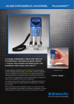
1
LCD display
Figure 9: Readout unit
5.3
How it works
To monitor the axial load in a SAFEBOLT-instrumented bolt, the user first hooks the
SAFEBOLT-instrumented bolt head to the readout unit via the cable to take the initial signal
reading, A, before the installation of the bolt, i.e. before any load is applied to the bolt. Such
signal represents the zero strain or gauge balancing factor. As the load is applied to the bolt
(either in the laboratory or in the field), the readout unit will register a signal of magnitude R.
Thus the axial strain due to applied load is represented by the quantity R-A. The axial strain can
be written as a function of (R-A). Thus,
ε = F [(R-A)]
[2]
Referring to Equation [1], the axial load, P can be written as
P = F [(R-A), Ab, Eb]
[3]
The above equation allows for the calculation of the bolt axial load, P. It can be rewritten as:
P (tonnes) = [R-A] ×B
[4]
Where
A= Gauge bridge balancing factor, obtained from the initial signal reading when connected to the
SAFEBOLT device before loading. The value of A could be negative or positive.
B = Readout unit calibration constant, obtained from the calibration of the SAFEBOLT device as
will be explained below. B is a function of Ab and Eb.
11