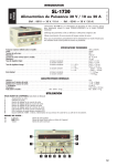
1
PS1 Sinewave Interactive Inverter
Charger
Technical Manual
Document: PC0009
Revision 05
Technical Manual
PS1 Sinewave Interactive Inverter Charger
About This Manual
This manual (PC0009) contains information for installation, maintenance and troubleshooting of the PS1
Sinewave Interactive Inverter Charger family. These activities should be performed by suitably qualified and
trained personnel only.
The indicated values are for a PS1 10/48. Refer to C.1 for a list of applicable models and to C.2 for
document and software revision information.
This manual must be read in conjunction with the user manual. The User Manual (PC0004) describing the
operation is available. Refer to Appendix C for document and software revision information.
A PDF copy of this manual may be downloaded from the Selectronic web site www.selectronic.com.au PDF
copy includes many cross-reference hotlinks (underlined) to facilitate moving around within the document.
(If you have clicked one of these links and wish to return to the place where you were previously reading,
click on the “Go to Previous View” symbol on the Acrobat Reader toolbar at the top of the document.)
Contact your supplier or the manufacturer (see below) to order a printed copy of this manual (see manual
details in page footer below).
In this manual, the symbol
indicates important information such as hazards and warnings.
If you have any suggestions for improvements to either this manual or any Selectronic Australia product
please contact us (see Manufacturers Details below).
Warning
The equipment described in this manual may be hazardous. Before operating the equipment please see 1
Precautions and Safety and ensure that you understand the relevant information in the manual. Procedures
in this manual require the PS1 front door to be opened, only suitably qualified and trained installation,
commissioning and maintenance personnel should open the PS1 door or disturb the PS1 wiring.
Selectronic Australia shall have no obligation as to any equipment which has been improperly installed,
stored, or handled, or which has not been operated or maintained according to this manual, nor for any
operating mistakes and consequences arising therefrom.
This product is not to be used for Life Support equipment.
Manufacturers Details
Selectronic Australia Pty Ltd
Suite 5, 20 Fletcher Rd
Mooroolbark VIC 3138
Australia
Ph +61 3 9727 6600
Fax +61 3 9727 6601
[email protected]
www.selectronic.com.au/
© Selectronic Australia 2006
Document PC0009 Revision 05
Page 2 of 97
Technical Manual
PS1 Sinewave Interactive Inverter Charger
Contents
About This Manual.................................................................................................................. 2
Warning .................................................................................................................................... 2
Manufacturers Details ............................................................................................................ 2
Contents ................................................................................................................................... 3
1
Precautions and Safety ................................................................................................... 7
1.1 Multiple Hazardous Energy Sources.......................................................................... 7
1.2 Heavy........................................................................................................................... 7
1.3 Installation.................................................................................................................... 7
1.4 Maintenance................................................................................................................ 7
1.5 Inverter or Generator may Start Automatically........................................................... 7
1.6 Battery ......................................................................................................................... 7
1.7 Generator .................................................................................................................... 8
1.8 Renewable Sources.................................................................................................... 8
2
Site Selection.................................................................................................................... 9
3
PS1 Wiring....................................................................................................................... 11
3.1 External Wiring Schematic........................................................................................ 11
3.2 DC Power Wiring....................................................................................................... 12
3.2.1 Fuses.................................................................................................................. 12
3.2.2 DC Cables .......................................................................................................... 13
3.2.3 DC Earth and Lightning Protection.................................................................... 13
3.3 AC Power Wiring....................................................................................................... 13
3.3.1 Circuit Breakers.................................................................................................. 13
3.3.2 Residual Current Device.................................................................................... 13
3.3.3 AC Cables .......................................................................................................... 13
3.3.4 AC Generator Connection ................................................................................. 13
3.3.5 Earthing .............................................................................................................. 13
3.3.6 Labelling ............................................................................................................. 14
3.4 External Alarm Wiring ............................................................................................... 14
3.5 Generator Control Wiring.......................................................................................... 14
3.5.1 Wiring Diagrams................................................................................................. 14
3.5.1.1 Generator Run by contact closure .....................................................15
3.5.1.2 Generator On and Start by contact closures......................................15
3.5.1.3 Generator Pulsed On and Off by voltage inputs ................................15
3.5.2 Control Signals................................................................................................... 16
3.6 Shunt Wiring.............................................................................................................. 16
3.6.1 Wiring Diagrams................................................................................................. 16
3.6.1.1 Renewable Only – Shunt 1 ................................................................16
3.6.1.2 Renewable and DC Load – Shunt 1 and Shunt 2 ..............................17
3.6.1.3 Net Renewable and DC Load – Shunt 1 Only ...................................18
3.6.2 Shunt Inputs ....................................................................................................... 18
4
Installation....................................................................................................................... 19
4.1 Inspection .................................................................................................................. 19
4.2 Mounting.................................................................................................................... 19
4.2.1 Shelf Mounting ................................................................................................... 19
4.2.2 Wall Mounting – Hanging Bracket..................................................................... 20
4.3 Additional Componentry ........................................................................................... 21
4.4 Wiring......................................................................................................................... 21
4.4.1 DC Wiring ........................................................................................................... 22
4.4.2 Battery Temperature Sensor ............................................................................. 22
4.4.3 Shunt Monitoring ................................................................................................ 22
4.4.4 Earth Wiring........................................................................................................ 23
4.4.5 AC Wiring ........................................................................................................... 23
© Selectronic Australia 2006
Document PC0009 Revision 05
Page 3 of 97
Technical Manual
PS1 Sinewave Interactive Inverter Charger
4.4.6 Generator Control .............................................................................................. 23
4.4.6.1 Minimum Control Wiring.....................................................................23
4.4.7 External Alarm.................................................................................................... 23
4.4.8 Serial Port cable................................................................................................. 23
5
Commissioning .............................................................................................................. 24
5.1 Inspection .................................................................................................................. 24
5.1.1 Wiring.................................................................................................................. 24
5.1.2 Polarity................................................................................................................ 24
5.2 Initial Power Up ......................................................................................................... 24
5.2.1 Door Open.......................................................................................................... 24
5.2.2 Door Closed ....................................................................................................... 24
5.3 Configuration ............................................................................................................. 25
5.4 AC Load..................................................................................................................... 25
5.5 Generator Synchronisation and Stability.................................................................. 26
5.5.1 Configuration ...................................................................................................... 26
5.5.2 Test – Generator Synchronisation..................................................................... 26
5.5.3 Test – Generator Stability .................................................................................. 26
5.6 Automatic Generator Control.................................................................................... 27
5.6.1 Configuration ...................................................................................................... 27
5.6.2 Test..................................................................................................................... 27
5.7 Shunt Inputs .............................................................................................................. 27
5.7.1 Enable Shunts.................................................................................................... 27
5.7.2 Zero Offset.......................................................................................................... 27
5.7.2.1 Set Shunt Zero Offset ........................................................................28
5.7.3 Shunt Size .......................................................................................................... 28
5.7.4 Shunt Readings.................................................................................................. 28
5.8 System Operation ..................................................................................................... 28
6
PS1 Installer Menus ....................................................................................................... 29
6.1 Menu Structure.......................................................................................................... 29
6.1.1 Installer Menu Access........................................................................................ 31
6.2 Battery Settings ......................................................................................................... 32
6.3 Generator settings..................................................................................................... 37
6.4 AC Output settings .................................................................................................... 46
6.5 Shunt Settings ........................................................................................................... 48
6.6 Charger Settings ....................................................................................................... 52
6.6.1 Advanced Charger Settings............................................................................... 57
6.6.2 Additional Displays............................................................................................. 59
7
PS1 Technical Description............................................................................................ 60
7.1 Inverter Internal View ................................................................................................ 60
7.2 Inverter Block Diagram ............................................................................................. 62
7.2.1 DC and AC Power Circuits ................................................................................ 62
7.2.2 Inverter Management......................................................................................... 63
7.2.3 Power to the Inverter Electronics....................................................................... 64
7.2.4 Electromagnetic Interference (EMI) Filtering..................................................... 64
8
PS1 Operation................................................................................................................. 65
8.1 Battery Management................................................................................................. 65
8.1.1 Battery State of Charge (SoC) monitoring and control..................................... 65
8.1.2 Battery Voltage monitoring and control ............................................................. 66
8.1.3 Battery Charger Operation................................................................................. 66
8.1.3.1 Initial ..................................................................................................66
8.1.3.2 Bulk ....................................................................................................66
8.1.3.3 Absorb ...............................................................................................66
8.1.3.4 Float ...................................................................................................66
8.1.3.5 Equalise .............................................................................................66
8.1.4 Battery Temperature.......................................................................................... 68
8.2 Renewable Management.......................................................................................... 68
© Selectronic Australia 2006
Document PC0009 Revision 05
Page 4 of 97
Technical Manual
PS1 Sinewave Interactive Inverter Charger
8.3 Automatic Generator Control.................................................................................... 68
8.3.1 Generator Control based on SoC...................................................................... 69
8.3.1.1 Example Configuration 1 – Solar + Generator...................................70
8.3.1.2 Example Configuration 2 – Generator Charger .................................71
8.3.1.3 Example Configuration 3 – Poor Setup..............................................72
8.3.2 Generator Control based on Battery Voltage.................................................... 72
8.3.3 Generator Control based on AC Load .............................................................. 72
8.3.4 Generator Automatic Stopping .......................................................................... 73
8.3.5 Generator Scheduling........................................................................................ 73
8.4 Manual Generator Control ........................................................................................ 73
8.4.1 Remote Run Input.............................................................................................. 73
8.5 Generator Fault Recovery ........................................................................................ 74
8.6 Generator Control Interface ...................................................................................... 74
8.6.1 Generator Available Signal................................................................................ 74
8.6.2 Generator Start/Stop Signals:............................................................................ 75
8.6.3 Generator Status Signals:.................................................................................. 75
8.7 Synchronisation......................................................................................................... 75
8.8 System Power Flow .................................................................................................. 75
8.8.1 No Generator/PS1 switched ON ....................................................................... 75
8.8.2 PS1 ON/ Generator Started............................................................................... 75
8.8.3 Generator ON/PS1 switched ON ...................................................................... 76
8.8.4 Load Sharing...................................................................................................... 76
8.8.5 Reverse Power................................................................................................... 76
8.8.6 Reactive Power .................................................................................................. 76
8.9 Inverter External Alarm ............................................................................................. 76
9
Troubleshooting............................................................................................................. 77
9.1 System General Check............................................................................................. 77
9.2 Inverter will not Start.................................................................................................. 77
9.3 No AC Power to Load while Generator Off .............................................................. 77
9.4 Inverter Not Charging Battery ................................................................................... 77
9.5 Inverter Shuts Down.................................................................................................. 77
9.6 Inverter – No Front Panel display ............................................................................. 78
9.7 DC Circuit Breaker Trips ........................................................................................... 78
9.8 Inverter does not start Generator ............................................................................. 78
9.9 Inverter does not synchronise to Generator............................................................. 78
9.10 Inverter synchronises but disconnects due to reverse power flow.......................... 79
9.11 Inverter & Generator Load Sharing Incorrect........................................................... 79
9.12 Generator Runs at the Wrong Times ....................................................................... 79
9.13 The Generator Runs for a Long Time ...................................................................... 80
9.14 Incorrect Inverter AC Voltage ................................................................................... 80
9.15 Incorrect Battery Charging........................................................................................ 80
10 Inverter Shutdown & Isolation Procedures ................................................................ 81
10.1 Inverter Shutdown Procedure................................................................................... 81
10.2 Inverter Isolation Procedure...................................................................................... 81
10.3 Inverter Discharge Procedure................................................................................... 81
10.4 Inverter De-isolation Procedure................................................................................ 82
10.5 Inverter Start-up Procedure ...................................................................................... 82
Appendix A Specifications .................................................................................................. 83
A.1 Product Specifications............................................................................................... 83
A.2 Standards Compliance ............................................................................................. 85
A.3 Generator Control Interface Specification ................................................................ 85
Control Relays.................................................................................................................. 85
Output functions ............................................................................................................... 85
Control Inputs ................................................................................................................... 86
A.4 Alarm Interface Specification .................................................................................... 87
Relay 87
A.5 Shunt Interface Specification .................................................................................... 87
© Selectronic Australia 2006
Document PC0009 Revision 05
Page 5 of 97
Technical Manual
PS1 Sinewave Interactive Inverter Charger
Measurement Inputs ........................................................................................................ 87
A.6 Serial Port.................................................................................................................. 87
A.7 Battery Cable Recommendation .............................................................................. 88
A.8 Battery Fuse Recommendation................................................................................ 88
A.9 Mechanical Details .................................................................................................... 89
Appendix B Definitions ........................................................................................................ 92
B.1 Settings Index............................................................................................................ 92
B.2 Event Definitions ....................................................................................................... 93
B.3 Self Test Fault Codes................................................................................................ 96
Appendix C Revisions and Changes ................................................................................. 97
C.1 Revisions to this Document ...................................................................................... 97
C.2 Software Version Applicability .................................................................................. 97
© Selectronic Australia 2006
Document PC0009 Revision 05
Page 6 of 97
Technical Manual
PS1 Sinewave Interactive Inverter Charger
1 Precautions and Safety
1.1 Multiple Hazardous Energy Sources
Hazardous voltages and energy are generated by the PS1, are fed into the PS1 by external wiring from
multiple sources, and may be stored in capacitors after the PS1 is switched off and disconnected from
external wiring.
Do not operate with the door open. No operating procedures in this manual require the PS1 door to be
opened. All PS1 operations are performed with the door closed. This includes the front panel operation of
all PS1 pushbuttons, displays and circuit breakers.
Only suitably qualified and trained personnel should open the PS1 front door.
Installation procedures in this Technical Manual require the PS1 front door to be opened to access internal
wiring terminals and connectors. All commissioning and test procedures are performed with the door closed
except where explicitly stated in this manual.
1.2 Heavy
The PS1 is heavy (up to 98kg). Take care when lifting and moving the PS1. Use appropriate mechanical
lifting aids to move the PS1. Four eye bolts (provided) can be screwed into the top of the PS1 cabinet for
attaching a lifting harness.
1.3 Installation
The PS1 requires adequate ventilation, away from hot equipment. Do not obstruct the airflow through the
ventilation holes in the PS1 case (sides, rear and door top). Ensure when installed in an enclosed space
that there is adequate ventilation.
The PS1 must be located in a dry place away from water, electrolyte and corrosive aerosols.
The PS1 contains arcing contacts so must not be located where explosive gas mixtures could occur, such
as hydrogen from batteries or diesel fuel fumes. The PS1 must never be installed above the battery bank.
1.4 Maintenance
Ensure that all energy sources are isolated before working on connected wiring. The generator may start or
power may be restored by the inverter at any time
Never work on equipment or investigate a problem without following appropriate safety isolation procedures.
Procedures are defined in the PS1 Technical Manual.
1.5 Inverter or Generator may Start Automatically
The PS1 automatically starts and/or restarts and may restore power or start the generator at any time.
If a fault or overload is detected the PS1 will shutdown and automatically attempt to restart at varying
intervals of up to several hours.
1.6 Battery
Batteries are very dangerous. Please read the safety information provided by the battery supplier.
Battery acid is dangerous.
Batteries can emit hydrogen gas, which is explosive.
Batteries connected in series can produce hazardous voltages.
© Selectronic Australia 2006
Document PC0009 Revision 05
Page 7 of 97
Technical Manual
PS1 Sinewave Interactive Inverter Charger
Disconnecting a DC power connection (even on one battery cell) can cause dangerous high-energy DC
arcs, which can cause serious burns and eject hot particles, and can be difficult to extinguish.
Disconnecting a DC power connection (even on one battery cell) can cause renewable sources to produce
large voltages (much larger than the battery voltage) on battery terminals and DC wiring. Such voltages can
be lethal. They can also damage the PS1. Only suitably trained and qualified personnel should disconnect
any DC power connection, including battery cell connections, and only with suitable procedures and safety
precautions.
1.7 Generator
Please read the safety information provided by the generator supplier.
The generator produces hazardous voltages.
The generator installation should follow relevant standards and practices for the installation of fuel storage,
for ventilation and dispersal of exhaust gas. Exhaust gas in enclosed spaces can kill.
The generator installation should include a means of isolating the generator automatic control inputs from
the PS1. The generator must be isolated from the PS1 during servicing.
The PS1 automatically starts and/or restarts and may restore power or start the generator at any time.
Never work on equipment or investigate a problem without following appropriate safety isolation procedures,
including turning off isolating switches and disconnecting the generator start battery.
1.8 Renewable Sources
Please read the safety information provided by the supplier.
Renewable sources can produce hazardous voltages.
Shorting or disconnecting renewable wiring which is energized or carrying current can produce dangerous
DC power arcs which are difficult to extinguish.
© Selectronic Australia 2006
Document PC0009 Revision 05
Page 8 of 97
Technical Manual
PS1 Sinewave Interactive Inverter Charger
2 Site Selection
The inverter performance rating is dependent on the environmental operating conditions, in particular
ambient temperature and ventilation. There are also safety considerations that must be addressed.
Appropriate site selection and preparation are fundamental to getting the optimum performance from the
PS1.
The site should be selected and prepared to provide:
•
A dedicated lockable power room/area for PS1 and associated equipment.
•
No access to unauthorized personnel or children.
•
Maintenance of the ambient temperature within the product specification (see Appendix A).
•
Adequate ventilation, away from hot equipment. Ensure unobstructed airflow through the
ventilation holes in the inverter case (sides and door top). See A.9 Mechanical Details for air flow.
min
150mm
min
150mm
Air In
Air Out
•
A dry location away from water, condensation, electrolyte and corrosive aerosols.
•
A location free from the risk of explosive gas mixtures occurring, such as hydrogen from batteries
or diesel fuel fumes. The inverter contains arcing contacts which may ignite such mixtures. Never
mount the PS1 above batteries.
•
Rodent proof.
•
A mounting surface and method suitable for the inverter weight with adequate safety margin (see
Appendix A.1 Product Specifications for unit weight). If the inverter is wall mounted the mounting
method must be in accordance with the installation instructions using the fasteners specified.
•
Sufficient space available in front of the inverter to open the inverter door and work on the inverter
internals.
Following the guidelines below will help maintain the system reliability and maximise the life of the PS1,
generator and other components.
•
Reduce operating temperatures. All equipment will provide longer and more reliable service if
protected from high temperatures and regular wide temperature variations. PS1 power capacity is
reduced when operating in high ambient temperatures.
•
In hot areas a shed or room with a shade roof above and on walls exposed to direct sunlight and
with reasonable ventilation will reduce maximum temperatures.
•
In areas with wide temperature variation between day and night, insulate the building and fit
ventilation controlled by internal room temperature to dispose of excess heat.
•
Install the generator in an area with good ventilation and well separated from the PS1 and the
batteries. Do not allow heat or exhaust from the generator to heat the PS1, the battery or other
equipment.
© Selectronic Australia 2006
Document PC0009 Revision 05
Page 9 of 97
Technical Manual
PS1 Sinewave Interactive Inverter Charger
•
Follow the instructions for routine monitoring and maintenance.
•
Monitor the performance of the system by periodically reviewing the PS1 logged data. The logged
data may indicate the system is not performing optimally and system settings changes or some
maintenance may be required. A telephone line and a modem connected to the PS1 will allow the
logged data and settings to be reviewed remotely.
© Selectronic Australia 2006
Document PC0009 Revision 05
Page 10 of 97
Technical Manual
PS1 Sinewave Interactive Inverter Charger
3 PS1 Wiring
The electrical wiring recommendations herein apply to Australia and New Zealand, and are based on
standard AS4509 – Standalone Power Systems.
The PS1 has been designed to comply with AS/NZS 3100 - General Requirements for Electrical Equipment
and as such can be installed into a system and be compliant with AS/NZS 3000 - Electrical installations as
required by AS4509.
For other regions, the installation and wiring should comply with relevant national standards and practices.
3.1 External Wiring Schematic
Figure 1 is a typical schematic of wiring connected to the inverter via the site switchboard. This wiring
scheme facilitates inverter bypass and also isolation of the inverter, generator and loads at one location.
Note: This schematic is intended to guide the designers of systems using the inverters. Do NOT use this
typical schematic to trace actual site wiring, which may differ in detail from that shown below.
Battery temp
sensor
Bundled
(see text)
Regulator
Array Pos
Array Neg
Pos
Neg
Batt Batt
Pos Neg
PV
Isolation
Switch
Inverter
Isolator
PS1
Bundled
(see text)
Bundled
(see text)
Load
Residual
Current
CB
Load
Neutral
Bar
Neutral Bar
Earth
Internal
Shunt
Renew Neg
Batt Pos
Batt Neg
Inverter
earth stake
Gen Active
Battery
fuses
Load
Main
CB
Load Active
Neutral
Renewable
fuse
3 fuses
ganged
(see text)
Load circuits
AC Switchboard
Solar Array
Control
PCA
Inverter
Bypass
Earth Bar
Generator
Isolator
Termination
PCA
A N E
Battery
temp
Battery sensor
Modem
or PC
etc
Earth
Neutral
Link
Remote
Gen Run
switch
External
alarm
Generator
controls Generator
Switchboard
earth
stake
Figure 1 External Wiring Schematic 1
Figure 2 is a typical schematic of wiring connected to the inverter with the generator wiring connected
directly to the inverter rather than via the site switchboard. Isolation of each component must be performed
at different locations. The generator cannot be connected directly to the loads without going through the
inverter.
Note: This schematic is intended to guide the designers of systems using the inverters. Do NOT use this
typical schematic to trace actual site wiring, which may differ in detail from that shown below.
© Selectronic Australia 2006
Document PC0009 Revision 05
Page 11 of 97
Technical Manual
PS1 Sinewave Interactive Inverter Charger
Battery temp
sensor
Bundled
(see text)
Regulator
AC Switchboard
Load circuits
Solar Array
DC Load
Array Pos
Array Neg
Pos
Neg
Batt Batt
Pos Neg
Neg Pos
Load
Main
CB
PV
Isolation
Switch
External
Shunt
PS1
Bundled
(see text)
Isolation
Switch
Load Active
Neutral
Bundled
(see text)
Renewable
fuses
DC Load
fuses
Load
Residual
Current
CB
4 fuses
ganged
(see
text)
Battery
fuses
Neutral Bar
Earth
Internal
Shunt
Renew Neg
Batt Pos
Batt Neg
Load
Neutral
Bar
Earth
Neutral
Link
Inverter
earth stake
Earth Bar
Gen Active
Control
PCA
Termination
PCA
A N E
Battery
temp
Battery sensor
Modem
or PC
etc
Generator
controls
External
alarm
Switchboard
earth
stake
Generator
Remote
Gen Run
switch
Figure 2 External Wiring Schematic 2
3.2 DC Power Wiring
The following sections refer to the 3.1 External Wiring Schematic.
3.2.1
Fuses
The battery fuses shown (or circuit breakers if desired) are necessary to protect the DC wiring. The fuses
should be rated to handle the maximum current flow during normal operation. The renewable fuses should
be rated to protect the wiring from back feed from the battery. The fuse ratings should be coordinated with
conductor sizes and temperature ratings.
For recommended fuse sizes refer to §A.8 Battery Fuse Recommendation.
It must not be possible to supply renewable power to the inverter with the battery disconnected, since the
inverter can be damaged by uncontrolled sources which are not voltage-limited by the battery. Therefore the
renewable and battery fuses should be “ganged” together in one physical assembly to ensure they are all
removed together.
The removable ganged fuse assembly also allows isolation of the renewable source, the battery and the
inverter from each other before working on them.
To prevent dangerous DC arcs, it must be possible to ensure that negligible DC current is made or broken
when connecting or disconnecting any DC Power Wiring. For example before working on the battery wiring,
the inverter is switched off via its On/Off button, the renewable regulator is switched off, and the battery is
isolated from the renewable source and from the inverter by removing the ganged fuse assembly.
© Selectronic Australia 2006
Document PC0009 Revision 05
Page 12 of 97
Technical Manual
3.2.2
PS1 Sinewave Interactive Inverter Charger
DC Cables
The high current wiring within the battery stack, and between the battery and the inverter, should be as direct
as possible, with the positive and negative cables bundled close together. This minimizes the wiring
inductance which assists the overall efficiency of the inverter system.
For recommended battery cable sizes refer to A.6 Battery Cable Recommendation.
The DC terminals for battery and shunt connection are M8 studs. Suitable lugs must be used for connection
to these studs.
Similarly the high current wiring between the battery and the renewable regulator, and between the regulator
and the renewable array, should be bundled and as direct as possible.
The DC cabling should be kept separated from the AC cabling.
3.2.3
DC Earth and Lightning Protection
The system earthing strategy for lightning protection will depend on specific site characteristics hence is left
to the judgement of the system designer/installer. The standard AS/NZS 1768 – Lightning Protection
provides details of lightning protection schemes.
To reduce the risk of accidental short circuits, earthing the DC Power Wiring is not recommended. If the
lightning protection scheme calls for the earthing of the DC wiring, the DC earth conductors must be
separate the AC Earth system and the DC Earth cables must be capable of caring the battery fault current
and blow the fuse before the earth cabling fails due to the fault current.
The control electronics are wired to battery negative.
3.3 AC Power Wiring
The following sections refer to the 3.1 External Wiring Schematic.
3.3.1
Circuit Breakers
The circuit breakers in the PS1 are designed to protect the wiring inside the PS1 and under normal operating
conditions, including faults on sub circuits will not normally trip. External AC wiring must be protected with
suitably rated external circuit breakers.
3.3.2
Residual Current Device
The Residual Current Device (RCD) installed in the AC Switchboard as shown protects the AC Load circuits
ONLY. A fault in the inverter and/or the generator cabling is not RCD protected and hence will not trip the
device RCD.
3.3.3
AC Cables
AC cabling must be sized appropriately for the application.
AC cabling should be kept separated from the DC cabling.
3.3.4
AC Generator Connection
The generator should be hard wired into the inverter system.
If the generator is to be plugged into the system, if disconnected while synchronised, voltage from the
inverter may be present on the plug. In this arrangement the requirements of AS4509.1 must be adhered to.
3.3.5
Earthing
It is recommended the inverter be earthed to its own earth stake adjacent to the inverter, and also to the
switchboard. Ensure the earth cable is suitable to carry the fault current and not fail before the circuit
breakers trip. Using the same size conductors as the AC cables ensures the earth wiring will carry the fault
current.
High Earth Leakage Current. Unit must be earthed before connecting to supply or operating unit.
Do not use the protective earth terminal for battery earthing.
© Selectronic Australia 2006
Document PC0009 Revision 05
Page 13 of 97
Technical Manual
3.3.6
PS1 Sinewave Interactive Inverter Charger
Labelling
Multiple power sources (inverter and generator) which may start or re-start at any time provide power to the
AC Switchboard. It is recommended that a warning label be fitted to all electrical power terminations at each
location and to isolators feeding the location, together with a basic electrical diagram indicating the power
sources and isolators.
Suggested warning label:
Multiple Hazardous Energy Sources
Ensure that all energy sources are isolated before working on connected wiring.
Inverter or Generator may Start Automatically
The generator may start or power may be restored by the inverter at any time.
A sheet of labels with the above text is provided with each PS1.
3.4 External Alarm Wiring
The external alarm is provided by an isolated NO/NC (normally open or normally closed) relay contact. This
relay contact is NOT fused. Any external wiring connected to this contact must be fused to protect the wiring
and relay contact.
See A.4 Alarm Interface Specification for contact ratings.
An alarm condition is indicated with the coil being de-energised. With the inverter in the Off state, the
external alarm should be active.
The following is an example showing how a light could be connected to the alarm relay.
PS1 Termination PCA
J9
ALARM
10
11
12
Light or Buzzer
Fuse
Battery
Bank
Figure 3 External Alarm
3.5 Generator Control Wiring
3.5.1
Wiring Diagrams
There are many different generator controllers and generator start/stop control schemes. The PS1
generator controller has been designed to interoperate with as many different types of controller as possible.
Depending on the type of controller these wiring diagrams will need to be adapted to suit the particular
controller.
All diagrams include a Generator Available control switch. This switch should be located as close as
practicable to the generator. This switch is used to prevent the PS1 automatically starting the generator
whilst being serviced. When in the open state (as shown) the PS1 will indicate that the generator is not
available and will not attempt to automatically start the generator.
The diagrams also include information regarding other control inputs to the PS1. They are shown separately
on each diagram for clarity only – they may be used together or in any combination.
See A.3 Generator Control Interface Specification
© Selectronic Australia 2006
Document PC0009 Revision 05
Page 14 of 97
Technical Manual
3.5.1.1
PS1 Sinewave Interactive Inverter Charger
Generator Run by contact closure
The following diagram shows a generator controller that only requires a voltage free contact closure to run
and stop the generator.
PS1 Termination PCA
Gen Run DO1
Gen Avail DI1
Gen Fault DI2
Gen Remote Run DI3
Common
J6
1
2
3
4
5
6
Low Fuel DI5
Fuel Empty DI6
J9
3
4
5
Gen Pulse D02
7
8
9
Generator Controller
Generator Available
Control Switch
Fuse
Start
Battery
Generator
Generator Remote
Run Switch
Figure 4 Generator Run
The diagram also includes a generator remote run switch. Closing the switch will cause the PS1 to start the
generator. This switch can be located in a convenient place away from both the generator and PS1.
3.5.1.2
Generator On and Start by contact closures
The following diagram shows a generator controller that requires a voltage free contact closure to turn the
generator ON and a pulsed control to start the generator. The time between when the Run relay closes and
when the Pulse relay closes is adjustable and for how long the pulse relay remains closed is also adjustable.
Generator Controller
PS1 Termination PCA
Gen Run DO1
Gen Avail DI1
Gen Fault DI2
Gen Remote Run DI3
Common
J6
1
2
3
4
5
6
Low Fuel DI5
Fuel Empty DI6
J9
3
4
5
Gen Pulse D02
7
8
9
Fault
Start
On
Common
Generator Available
Control Switch
Fuse
Start
Battery
Generator
Figure 5 Generator On Start
This diagram also includes an input from the generator indicating the generator has a fault. In this diagram
the fault output is a voltage free relay contact from the generator controller. It is necessary in this case to
feed volts from the start battery through this and then to the fault input.
3.5.1.3
Generator Pulsed On and Off by voltage inputs
The following diagram shows a generator controller that requires high level voltage input on one control line
to start the generator and a high level voltage input on a separate control line to stop the generator. In this
case the control signals must be transposed so the pulse signal is on DO1 and the run signal is on DO2.
© Selectronic Australia 2006
Document PC0009 Revision 05
Page 15 of 97
Technical Manual
PS1 Sinewave Interactive Inverter Charger
Generator Controller
Stop Input
Start Input
No Fuel Output
PS1 Termination PCA
Gen Avail DI1
Gen Fault DI2
Gen Remote Run DI3
Common
J6
1
2
3
4
5
6
Low Fuel DI5
Fuel Empty DI6
Common
J9
3
4
5
Gen Run DO1
Gen Pulse D02
Generator Available
Control Switch
Fuse
Start
Battery
Generator
7
8
9
Figure 6 Generator Pulse Start Pulse Stop
This diagram also includes an input from the generator indicating the generator has run out of fuel. In this
diagram the no fuel is a high voltage level output which feeds directly into the PS1 input. Note that the
additional common connection has been connected back to the start battery negative.
3.5.2
Control Signals
The generator run and the generator pulse signals are provided by either an isolated NO or NO/NC relay
contact. These relay contacts are NOT fused. Any external wiring connected to these contacts must be
fused or limited by other means to protect the wiring and relay contact.
These are control outputs only and not designed to take high generator running or start currents.
See A.3 Generator Control Interface Specification for contact ratings.
The generator control input signals are provided by current limited control inputs. These inputs are NOT
fused. Any external wiring connected to these inputs must be fused or limited by other means to protect the
wiring and control input.
See A.3 Generator Control Interface Specification for input ratings.
3.6 Shunt Wiring
3.6.1
Wiring Diagrams
The diagrams are indicative only. Each site will have differing requirements and these diagrams will need to
be adapted to suit the required configuration.
The PS1 provides one internal shunt connected between the Renewable Negative and Battery Negative
terminals as shown in Figure 8.
3.6.1.1
Renewable Only – Shunt 1
The following diagram shows a basic configuration with the renewable connected and monitored by Shunt 1.
The regulator output and the battery are connected in parallel, via the PS1 Shunt 1 which is to be used to
measure the renewable current. The Shunt settings do not need to be changed as this is the default
configuration.
© Selectronic Australia 2006
Document PC0009 Revision 05
Page 16 of 97
Technical Manual
PS1 Sinewave Interactive Inverter Charger
BATT
POS
Battery
Fuses
BATT
NEG
POS
Shunt 1
input
+
+
Renewable
source
Regulator
AC
Load
-PS1
Shunt 1
(internal)
NEG
Fuses
--
--
+
RENEW
NEG
Shunt 2
input
POS NEG
Figure 7 Renewable Connection
Since Shunt 1 is used to measure the renewable input no additional shunt sense wiring is required.
3.6.1.2
Renewable and DC Load – Shunt 1 and Shunt 2
In Figure 8 the internal shunt is used to monitor the renewable source using via shunt input 1. The Shunt 1
menu setting is configured to Renewable ON and DC Load OFF hence will interpret the measure current
as a renewable source current. A DC load connected to the battery and regulator can be monitored by the
PS1 using an external shunt via shunt input 2. The Shunt 2 menu setting is configured to DC Load ON and
Renewable OFF and hence will interpret the measure current as a load current.
BATT
POS
Battery
Fuses
BATT
NEG
POS
+
AC
Load
-PS1
Shunt 1
(internal)
Renewable
source
+
+
Regulator
NEG
Fuses
Shunt 2
input
--
--
POS NEG
Shunt
+
Fuses
DC Load
-Figure 8 Monitoring Renewable and DC Load
© Selectronic Australia 2006
Document PC0009 Revision 05
Page 17 of 97
Technical Manual
3.6.1.3
PS1 Sinewave Interactive Inverter Charger
Net Renewable and DC Load – Shunt 1 Only
In Figure 9 the internal shunt is used to monitor the renewable source and the DC load using an internal
shunt via shunt input 1. The Shunt 1 menu setting is configured to Renewable ON and DC Load ON and
hence will interpret a positive measure current as a renewable source current and a negative measured
current as a load current. The overall result is the net current into the battery.
BATT
POS
Battery
Fuses
BATT
NEG
POS
+
AC
Load
-PS1
Shunt 1
(internal)
Renewable
source
+
+
Regulator
NEG
Fuses
--
--
Shunt 2
input
POS
NEG
+
DC Load
Fuses
-Figure 9 Monitoring Net Current with Shunt 1
3.6.2
Shunt Inputs
The shunt monitoring is provided by two high impedance differential inputs – Shunt 1 and Shunt 2. These
inputs are NOT fused. Any external wiring connected to these inputs must be fused or limited by other
means to protect the wiring and shunt input.
See A.5 Shunt Interface Specification for input ratings.
The internal 100A/50mV shunt is factory connected to the Shunt 1 input. This may be disconnected and
used to monitor an external shunt as required.
Both Shunt 1 and Shunt 2 can be wired and configured to monitor a renewable source, a DC load or both
simultaneously resulting in a net current reading. See §6.5 Shunt Settings for details of configuration
options.
© Selectronic Australia 2006
Document PC0009 Revision 05
Page 18 of 97
Technical Manual
PS1 Sinewave Interactive Inverter Charger
4 Installation
PS1 installation should be performed only by suitably trained and qualified personnel.
Ensure that the installation site is in accordance with 2 Site Selection.
4.1 Inspection
Before shipment the PS1 was rigorously tested and dispatched in perfect working order. Due to the freight
distances and handling involved, the inverter should be inspected as follows before installing it or connecting
power to it:
1. Inspect packaging for signs of damage.
2. Remove packaging from unit and examine the inverter case and ensure there are no obvious signs
of damage.
3. Remove the PS1 from the shipping pallet by removing the two (2) bolts underneath the pallet.
4. Inspect the top of the pallet and the underneath of the PS1 and ensure there are no obvious signs
of damage.
5. With a suitable screwdriver unscrew the two front door retaining screws and open the door, to view
the various Printed Circuit Board Assemblies (PCA), interconnecting cables and connectors. See
7.1 Inverter Internal View.
6. Check all cable connectors to ensure they are properly seated in their sockets. Avoid pulling on the
cables or straining their connections. Note: Three pin cable under Power PCA is not connected.
7. Visually check all connections to circuit breakers and contactors.
8. If all connections are sound and there are no signs of damage to the inverter cabinet, proceed with
installation. If there are problems, please contact the inverter distributor.
Please retain the inverter packing material for use if the inverter needs to be shipped.
4.2 Mounting
The PS1 can be shelf or wall mounted. One half of the wall mounting bracket is pre assembled to the PS1.
This may be removed if not required.
The mounting position must ensure an adequate airflow. A minimum clearance of 150mm must be provided
adjacent to the ventilation inlet and outlet areas (see Appendix A.9 Mechanical Details for ventilation area
details).
The shipping pallet must not be used for mounting the PS1.
All wiring to the PS1 must pass through the inverter bottom. Ensure the mounting position allows for all of
the required cabling, taking note of the minimum bend radius of heavy DC wiring.
The PS1 is heavy. Ensure appropriate lifting techniques and mechanical lifting aids are used when moving
and mounting the PS1. Four eye bolts (provided) can be screwed into the top of the PS1 cabinet for
attaching a lifting harness. Unscrew and remove the four M4 hex bolts and the fibre washers from the top of
the cabinet and retain. Screw the four eye bolts with the fibre washers into position. The eye bolts should
be removed and the hex bolts replaced when the mounting has been completed.
4.2.1
Shelf Mounting
For shelf-mounting, the inverter can simply sit on the shelf, or can optionally be bolted to the shelf via M8
bolts up into the inverters rubber feet. See A.9 Mechanical Details for feet locations. It is recommended that
the PS1 be bolted into position.
The shelf must allow for the wiring beneath the inverter.
© Selectronic Australia 2006
Document PC0009 Revision 05
Page 19 of 97
Technical Manual
4.2.2
PS1 Sinewave Interactive Inverter Charger
Wall Mounting – Hanging Bracket
The wall mount position must be on a concrete or masonry wall using at least five (5) 8mm bolt diameter
Dynabolt sleeved anchors or equivalent of suitable length for the wall material, evenly spaced and fitted
according to manufacturer’s instructions.
Wall-mounting procedure:
•
The cabinet mounting bracket and two rubber bumpers are attached to the rear of the PS1 during
manufacture. Verify all bracket mounting bolts are tight.
•
Mount the Rear Hanging Bracket. Use the bracket as a template, with the bracket horizontal, mark
the hole positions on the wall. At least five evenly spaced mounting holes must be used.
• Install the anchors as per the anchor manufacturer’s recommendation.
•
Raise the PS1 and lower it onto the hanging bracket ensuring the location slots in the cabinet
mounting bracket mate with the hanging bracket location tongues.
•
Rest the lower portion of the PS1 against the wall on the two rubber buffers.
Figure 10 Wall Mounting Brackets
The PS1 stays in position due to its own weight.
© Selectronic Australia 2006
Document PC0009 Revision 05
Page 20 of 97
Technical Manual
PS1 Sinewave Interactive Inverter Charger
4.3 Additional Componentry
If any additional components are to be installed into the PS1 cabinet, they may be installed onto the raised
DIN rail. Take care to ensure that any disturbed internal wiring is re-connected to the same location.
Special attention is drawn to the small EMI leads fitted into the top of the AC and DC circuit breakers and
into the top of the neutral terminal.
DO NOT DRILL into the internal chassis of the PS1. The primary transformer is located directly behind the
chassis. The un-used pressed inserts in the chassis may be used to mount additional components. Use the
shortest possible (6mm) M4 Zinc Plated Steel screws.
Ensure that hazardous voltages cannot contact with the chassis or any other wiring. Check the clearance of
additional components to ensure the door will close correctly.
DO NOT utilise the chassis earth screw and stud points for any mounting or additional earth wiring.
4.4 Wiring
This section provides information regarding the wiring of the PS1 only.
Ensure all wiring is de-energised when making connections to the PS1. Ensure other power sources cannot
automatically start and energise wiring.
All wiring feeds up through the bottom of the PS1. A gland plate and cable gland nuts are provided for the
installation of all cable. Any unused cable cut-outs should be fitted with gland plugs to keep out vermin.
Suitable grommet edging material should be fitted to protect the wiring from sharp edges.
See Appendix A.9 Mechanical Details for cut-out details.
Wiring locations referred to in the following sections are indicated in Figure 11 DC and AC Wiring Locations
and Figure 12 Control Wiring Locations below. The same labels are also on the inside door of the PS1.
Figure 11 DC and AC Wiring Locations
© Selectronic Australia 2006
Document PC0009 Revision 05
Page 21 of 97
Technical Manual
PS1 Sinewave Interactive Inverter Charger
Figure 12 Control Wiring Locations
4.4.1
DC Wiring
DC wiring should be fed up through the appropriate cut out and terminated to the PS1. Ensure the
protective plastic cover remains in place after connecting DC cables.
Connect the lugged battery negative lead to the inverters Battery Negative terminal under the load washer
ensuring the face of the lug is directly against the PS1 contact surface. Tighten the nut with a calibrated
torque wrench to 8 Nm.
If required, similarly connect the renewable negative lead to the inverters Shunt 1 Negative terminal.
Similarly connect the battery positive lead to the inverters Battery Positive terminal.
4.4.2
Battery Temperature Sensor
A battery temperature sensor is supplied pre-wired within the inverter. Pass the sensor and its wiring out
through the inverter bottom cut-out, and mount the sensor in thermal contact with the centre of the side of a
battery. It is good practice to insulate the sensor from the ambient air by covering the sensor when mounted
to the battery with insulating material.
If the sensor cabling is not long enough, disconnect the sensor wiring from J8 on the termination PCB and
add the additional cable. Ensure to insulate the joins.
The sensor is polarity sensitive – ensure that the correct polarity is maintained.
4.4.3
Shunt Monitoring
The sense wires for the externals shunts should be fed up through the appropriate cut out and terminated to
the PS1. The sense cabling should be kept as short as possible. “CAT5” type cabling or any multi
conductor multi strand cable is suitable for shunt sense wiring. Remember that these small cables are
connected to battery negative and an inadvertent short circuit with either lead to battery positive would short
circuit the battery bank. It is recommended that both these wires be separately fused.
The polarity of these shunt leads is not important if the shunt is to be used for either a renewable input or a
DC load. The shunt settings compensate for the direction of current flow. If the shunt will be used to
measure the Net between renewable and load then the polarity is very important. Ensure the positive shunt
connection goes to the positive shunt sense and that the current is flowing in the correct direction.
See 6.5 Shunt Settings.
© Selectronic Australia 2006
Document PC0009 Revision 05
Page 22 of 97
Technical Manual
4.4.4
PS1 Sinewave Interactive Inverter Charger
Earth Wiring
Earth the inverter by connecting earth wiring from the switchboard earth stake to the inverter earth stake,
and from the inverter earth stake to the inverter Earth terminal.
4.4.5
AC Wiring
AC wiring should be fed up through the appropriate cut out and terminated to the PS1. Ensure the
protective plastic cover over the DC connections remains in place.
Connect the AC load wiring to the PS1: earth to either earth terminal, neutral to either neutral terminal, and
active to the Load Circuit Breaker.
Connect the AC generator wiring to the PS1: earth to either earth terminal, neutral to either neutral terminal,
and active to the Generator Circuit Breaker.
4.4.6
Generator Control
Generator control wiring should be fed up through the appropriate cut-out and terminated to the PS1.
“CAT5” type cabling or any multi conductor multi strand cable is suitable for all control wiring. The green
screw terminals can be plugged in and out of the termination PCA for ease of wiring.
Check what the generator controller requires to start and stop the generator and what type of outputs it
provides. See A.3 Generator Control Interface Specification.
4.4.6.1
Minimum Control Wiring
The generator run output must be connected so the PS1 can signal the generator to start and stop.
The generator available input should be fitted to indicate the generator is available to be automatically
started. If not fitted, the generator available override in the software must be set to ALWAYS. See 6.3
Generator settings.
Without the generator available installed, ensure that the PS1 start signal does not start the generator when
working on or servicing the generator.
4.4.7
External Alarm
Connect the External Alarm wiring to the inverter. “CAT5” type cabling or any multi conductor multi strand
cable is suitable. The green screw terminals can be plugged in and out of the termination PCA for ease of
wiring. Ensure appropriate fuses are fitted to protect the wiring and relay.
The alarm should activate since the inverter is presently out of service.
4.4.8
Serial Port cable
The serial port cable should be connected into J16 on the Control PCA (see Figure 14 Behind Front Door)
and fed out through an appropriate cut-out. This allows for connection to the internal serial port without the
need for opening the PS1 front door. This cable can be left unconnected if not required. The serial port is
isolated from the PS1 and no hazardous voltages are present on the interface cable.
When installed check that the cable does not foul on any internal cables or components.
© Selectronic Australia 2006
Document PC0009 Revision 05
Page 23 of 97
Technical Manual
PS1 Sinewave Interactive Inverter Charger
5 Commissioning
This procedure is for the test and commissioning of the PS1. It does not cover other components in the
system however many of the tests described may exercise those components.
5.1 Inspection
No power should be applied at this stage.
5.1.1
Wiring
All connected wiring should be checked and tested for continuity and short circuits.
Check that no wiring feeding through the bottom cut-out is pressing against any sharp edges.
Check that any removed screw terminal plugs from the Termination PCA have been re-connected, correctly
aligned and are pressed firmly home.
Ensure that the DC stud insulating cover is in place.
Check that the DC and AC wiring is separated as much as possible.
5.1.2
Polarity
Ensure battery polarity is correctly wired to the PS1.
Ensure Active and Neutral terminals are correctly connected.
5.2 Initial Power Up
Read and understand the procedure below before proceeding.
Ensure that all the inverters front panel DC and AC circuit breakers are open. Renewable inputs should not
be connected at this stage. Ensure that the connected generator is shutdown and cannot start.
5.2.1
Door Open
Hazardous voltages are generated by the inverter and may also be fed into the inverter by external wiring
from multiple sources. The hazardous voltages may be stored in capacitors after the inverter is switched off
and disconnected from external wiring. The procedures below are to be performed only by suitably qualified
and trained personnel, taking appropriate safety precautions.
The initial DC connection is performed with the door open. The inverter’s front panel DC Circuit Breaker
remains open during this step.
Apply DC power to the inverter wiring by closing the external ganged battery/renewable DC fuse assembly
(or circuit breakers if used) - a small spark may be observed. Stop immediately and investigate if any fuse
blows or circuit breaker trips.
Check the RED LEDs on the lower edge of the power board. See 7.1 Inverter Internal View
LED1 should be ON
LED2 should be OFF
If LED1 is off, either power is not connected to the unit or the DC is connected in the reverse polarity. DO
NOT proceed until this corrected.
If LED1 is flashing, the connected DC voltage is incorrect. This is sometimes due to the initial power
connection. Press the front panel ON/OFF button once to reset the unit. LED1 should now be ON. If LED
continues to flash check battery voltages.
5.2.2
Door Closed
The front panel door should now be latched closed.
© Selectronic Australia 2006
Document PC0009 Revision 05
Page 24 of 97
Technical Manual
PS1 Sinewave Interactive Inverter Charger
Press and release the PS1 On/Off button. The indicator LEDs will come on and flash during self test.
When the LCD displays “Please close DC CB”, close the PS1 front panel DC Circuit Breaker. The self test
will complete and the PS1 will start. A low buzzing noise will be heard from the PS1.
The PS1 will now be producing 240VAC 50Hz output.
If self test fails, the error code will be displayed on the front panel LCD. See B.3 Self Test Fault Codes for
details.
Check the View Readings screens – (see PS1 User Manual)
Reading
Menu Reference #
Battery voltage and current readings
1.1
Power readings should all be 0
1.2
Temperatures should be close to ambient
1.6.1
5.3 Configuration
The PS1 is configured with default values for all settings; at least some of these are likely to be unsuitable for
your installation. Access the Installer menus via the front panel LCD and set up the system parameters to
suit the site requirements.
Importantly, before using the system, ensure that the settings for Batt Size Ah (6.2 Battery Settings) and
Gen:Max kW (6.3 Generator settings) are configured to suit the battery and generator size installed, and
that all battery charger settings (6.6 Charger Settings) are suitable for the battery type installed and conform
to the battery manufacturer’s recommendations.
If the Batt Size Ah setting is modified it is necessary to power cycle the PS1 for the correct SoC calculations
to be displayed.
The PS1 incorporates a number of other settings that effect the system operation. The following should be
considered when setting the system to suit the site requirements
•
SoC generator start levels and times - See 6.3 Generator settings
•
Load power generator start levels - See 6.3 Generator settings
•
Minimum generator run time – See User Manual
•
Frequency and voltage tolerance for generator input. Note: Some generators have low frequency
cut-outs; the Low Freq Tol must be set above these limits. When setting the voltage and frequency
limits, allowance must be made for the difference in frequency and/or voltage when the generator is
cold. The default low frequency tolerance is 48.0Hz. See 6.4 AC Output settings
5.4 AC Load
Ensure all circuits at the distribution board are open.
Close the AC Load circuit breaker on the inverter, while ensuring there is no change in inverter operation.
Close each load circuit breaker at distribution board and load test the PS1.
Reading
Menu Reference #
Verify power readings as each load is applied
1.2
Open the AC Load circuit breaker on the inverter.
© Selectronic Australia 2006
Document PC0009 Revision 05
Page 25 of 97
Technical Manual
PS1 Sinewave Interactive Inverter Charger
5.5 Generator Synchronisation and Stability
The objective of these tests is to set the highest Gen Type setting whilst still maintaining stable generator
operation. Generally, a generator will operate satisfactorily with the PS1 set to Gen Type 0, however
optimum generator performance (steady ramping to power and agile response to load change) may not be
achieved at this setting.
Stable generator operation is defined as when there is no oscillatory variation or “bouncing” in the generator
output. On abrupt changes in load, the generator may “bounce” briefly and then return to stable operation.
An easy way to detect “bouncing” is to look for flickering in a low wattage incandescent light globe connected
to the system.
This procedure should be carried out with the battery bank partially discharged to enable the largest battery
charge load to be applied to the generator. Ideally the inverter will be limiting on battery charge current with
battery voltage below the charge voltage.
5.5.1
Configuration
If a generator available control switch has been installed, then set it to the open position. See 3.5 Generator
Control Wiring. No other configuration of the generator control relays or inputs is required.
Set Gen Type to 0 (Default setting). See 6.3 Generator settings
Check the front panel LED indication Gen NOT available. This must be ON. By default with no generator
control wiring the indication is ON. If OFF, check generator available control switch (if installed) and Gen
Avail setting is “Follow I/P” (Default setting). See 6.3 Generator settings
Manually start the generator.
5.5.2
Test – Generator Synchronisation
Once the generator has started, close the generator circuit breaker.
The PS1 will attempt to synchronise and connect to the generator. The PS1 will display Manual Gen Start
when synchronised and the front panel LED indication “Inv – Sync” will be active.
If the generator voltage and/or frequency is out of range the Gen Freq Error or Gen Volt Error LED
indications will be active. If required, adjust 6.4 AC Output settings
5.5.3
Test – Generator Stability
The inverter will start to apply load to the generator by ramping up the charge power to the battery bank.
Check that the generator remains stable through this process.
If the generator is stable, close the AC Load circuit breaker and then switch various AC loads ON and back
OFF again. The AC loads will be firstly powered by the inverter and then transferred to the generator.
Check that the generator remains stable through this process.
If the generator is not stable on Gen Type 0 – See 9 Troubleshooting
button for one second. The PS1 will display Gen NOT Available then Manual
Press and hold the
Gen Stop. The PS1 will disconnect from the generator. Since the generator is still running, the PS1 will
however attempt to re-synchronise.
Open Generator circuit breaker.
If a Gen Type proves unstable, then there is no need in testing the remaining types. In this case, set the
Gen Type back to the previous setting.
To ensure the charging process is reset, it is necessary to wait at least two minutes between each test.
Repeat the steps 5.5.2 and 5.5.3 above with Gen Type set to 1, 2 and 3 to determine the most suitable
setting for the generator.
Once the correct setting has been achieved Manually shutdown the generator and open AC Load circuit breaker.
© Selectronic Australia 2006
Document PC0009 Revision 05
Page 26 of 97
Technical Manual
PS1 Sinewave Interactive Inverter Charger
5.6 Automatic Generator Control
5.6.1
Configuration
Set the generator control relay configuration to suit the generator controller. Generator controllers using only
the Gen Run signal do not require any changes. Controllers using the Gen Pulse signal may require the
Pulse Time and Pulse delay times adjusted to suit. See 6.3 Generator settings.
5.6.2
Test
Check the front panel LED indication Gen NOT available. If ON, close the externally wired generator
available control switch. See 3.5 Generator Control Wiring. If no control switch is installed (not
recommended) set the generator available override in the software to ALWAYS. See 6.3 Generator
settings.
Gen NOT available LED indication should turn OFF.
Press and hold the OK button for 1 second. The PS1 will display Gen Start and then display the PS1
voltage and frequency and generator voltage and frequency plus the variation in generator frequency.
** Gen Starting **
240
251
50.00
52.38
Delta Gen Hz
0.47
If the generator fails to start, press and hold the OK button for 1 second. The PS1 will display Gen Stop.
Verify the generator control wiring.
Once the generator has started, close the generator circuit breaker.
The PS1 will attempt to synchronise and connect to the generator. Check the front panel LED indications for
Inv – Sync indication. If the generator voltage and/or frequency is out of range the Gen Freq Error or Gen
Volt Error LED indications will be active.
Reading
Menu Reference #
Verify generator, inverter and load power
readings.
1.2
Press and hold the OK button for 1 second. The PS1 will display Gen Stop. The PS1 will attempt to stop
the generator.
If the generator doesn’t stop, check control wiring. Note: The generator may have a cool down period before
stopping.
Open the externally wired generator available control switch. Ensure the front panel LED indication Gen
NOT available comes ON.
Open Generator circuit breaker.
Check other control inputs (if fitted) to ensure the work as expected.
5.7 Shunt Inputs
5.7.1
Enable Shunts
The shunt inputs must be enabled and set to measure the renewable input or DC Load. If only the internal
shunt (Shunt 1) is being used to measure renewable then no changed to the default settings is required. For
other configurations, see 6.5 Shunt Settings and set the shunt configuration according to usage.
5.7.2
Zero Offset
Ensure no current is flowing through shunts.
© Selectronic Australia 2006
Document PC0009 Revision 05
Page 27 of 97
Technical Manual
PS1 Sinewave Interactive Inverter Charger
Reading
Menu Reference #
Verify that the shunts connected are reading 0.0
+/- 0.1 Amps
1.3
If the reading is greater than 0.1Amps then the zero offset requires adjustment.
5.7.2.1
Set Shunt Zero Offset
The following screens can be found in 6.5 Shunt Settings.
The procedure is the same for Shunt 1 and Shunt 2. Shunt 1 is shown here as an example.
Set both shunt type settings to ON - Renewable and DC load to ON.
Set Shunt 1 A/mV to 1.0
Adjust Shunt 1 Zero to the negative of Shunt 1 amp reading. (e.g. reading +1.5 enter -1.5, reading -2.5
enter +2.5). The indicated Shunt Amp reading will reduce to 0 +/- 0.1. The Shunt Amp reading is averaged
so the change can take up to a minute to settle to the new value.
Shunt1 Amp
Shunt 1 Zero
>
-5.0 <
PREV|NEXT
0.0
-1.5
5.0
EDIT|MENU
Reset the shunt type (Renewable ON/OFF and/or DC Load ON/OFF) and shunt size settings as required.
5.7.3
Shunt Size
The size of external shunts must be configured into the PS1. Shunt 1 by default is set to the size of the
internal 100A/50mV shunt.
The following screens can be found in 6.5 Shunt Settings.
The shunt size is set in Amps/mV or the number of amps flowing to give a 1millivolt reading.
The table below list some common shunt types and the associated setting:
Shunt
Setting
100A / 50mV 2.0
100A / 75mV 1.3
200A / 75mV 2.7
50A / 50mV
1.0
5.7.4
Shunt Readings
Connect renewable to unit.
Verify current readings are as expected. Compare the reading on the renewable regulator with
what is indicated on the PS1.
Verify the sign (+ or -) of the reading. If set to DC Load reading should be negative, if set to
Renewable reading should be positive.
5.8 System Operation
The PS1 is can now be set for normal operation. Close all circuit breakers and fuse assemblies.
Verify system operates as expected.
© Selectronic Australia 2006
Document PC0009 Revision 05
Page 28 of 97
Technical Manual
PS1 Sinewave Interactive Inverter Charger
6 PS1 Installer Menus
6.1
Menu Structure
The PS1 provides two levels of menus to configure and manage the system. User Menus that are used for
day to day operation of the system and Installer Menus are used to set up the system and thereafter are not
generally required by or accessible to the user.
The diagram below shows the menus structure for the PS1 settings and readings. The View Readings
menu is the home menu and will be displayed when the PS1 has completed power up. Use the four
and associated LCD text to navigate the menu structure. Refer to
pushbuttons
PS1 User Manual – User Interface for full details.
The View Readings, Summary Readings, View Diagnostics, View Settings, Generator Schedules and Event
Log menus allow viewing of system settings, readings and event history without the possibility of inadvertent
modification. The information provided in these screens is sufficient to monitor the day to day system
operation and resolve system problems. The Change Settings, Advanced Settings and Changes Schedules
menu allow modification of the PS1 User settings and generator run schedules. Refer to PS1 User Manual
– PS1 User Menus for full details.
The Battery Settings, Generator Settings, AC Output Settings, Shunt Settings, Charger Settings and
Advanced Charger Settings menus allow modification of the PS1 Installer settings and are only accessible
with installer access.
A screen number is written in this document with each display to assist with identifying the display e.g. 6.4 =
Main Menu Item 6(Battery Settings), Sub Item 4(Lvl 3 SoC%).
© Selectronic Australia 2006
Document PC0009 Revision 05
Page 29 of 97
Technical Manual
PS1 Sinewave Interactive Inverter Charger
1. View Readings
1.6 View
Diagnostics
PREV/NEXT
2. Summary Readings
PREV/NEXT
Event Log
3. View Settings
MENU|EVNT|
PREV|NEXT
4. Change Settings
4.8 Advanced
Settings
View Only
PREV/NEXT
User Edit
5. Generator
Schedules
5.5 Change
Schedules
PREV/NEXT
Back to “View Readings” unless Menu
Unlocked and Passcode Entered
Installer Edit
Menus
6. Battery Settings
PREV|NEXT
7. Generator Settings
PREV|NEXT
8. AC Output Settings
PREV|NEXT
9. Shunt Settings
PREV|NEXT
10. Charger Settings
10.16 Advanced
Change
PREV|NEXT
Back to “View Readings”
© Selectronic Australia 2006
Document PC0009 Revision 05
Page 30 of 97
Technical Manual
6.1.1
PS1 Sinewave Interactive Inverter Charger
Installer Menu Access
Installer settings are not accessible to the end user. Proper configuration of these settings requires in-depth
knowledge of the system requirements and parameters. Only suitably qualified and trained installation,
commissioning and maintenance personnel should access these menus.
To unlock the Installer menus:
1. Switch OFF the inverter using the ON/OFF pushbutton.
2. Open the inverter door and
(see §7.1 Inverter Internal View).
switch
ON
SW2
switch
7
on
the
Control
PCA
Control
PCA
3. Close the inverter door and switch ON using the ON/OFF pushbutton.
4. Edit the Passcode parameter in the Advanced User Settings menu.
5. Use the UP/DOWN buttons to enter the passcode (passcode is 41) and press OK.
6. The Installer menus will now be accessible for 2 hours.
7. The menus may be re-enabled after the 2 hours by repeating steps 4 and 5 above.
Subsequent unauthorised access to these menus by can be prevented by:
1. Switch OFF the inverter using the ON/OFF pushbutton.
2. Open the inverter door and
(see §7.1 Inverter Internal View).
switch
OFF
SW2
switch
7
on
the
3. Close the inverter door and switch ON using the ON/OFF pushbutton.
Failure to switch OFF SW2 switch 7 will allow a user, with knowledge of the static passcode, access to the
installer menus.
© Selectronic Australia 2006
Document PC0009 Revision 05
Page 31 of 97
Technical Manual
PS1 Sinewave Interactive Inverter Charger
6.2 Battery Settings
Refer to the battery manufacturer’s recommendations when setting battery parameters. Battery longevity
may be adversely affected by incorrect settings.
6.
RAPS
10kW 48V
Battery Settings
PREV|NEXT
Press
point.
16:59
OK
|MENU
to enter the View Settings screens. Within screens, press
at any time to return to this
6.1
Batt Size Ah
>
100, <
PREV|NEXT
1000
3200
EDIT|MENU
Battery Settings=>
Batt Size Ah: set battery size in ampere-hours configured in the system. This will be set
according to the battery size installed and the typical charge discharge profile.
Unit – Amp hours
Default 1000
Range 100 -> 3200
It is important to correctly configure this setting as State of Charge calculations and system
decisions are based on it.
Refer to the battery manufacturer’s documentation when setting the parameter.
6.2
Level 1 SoC%
>
50, <
PREV|NEXT
90
95
EDIT|MENU
Battery Settings=>
See 8.1.3 Battery Charger Operation.
Level 1 SoC%: the battery state of charge below which the generator will start in the
preferred generator run hour.
Unit - Percentage
Default 90
Range 50 -> 95
Level 1 is normally set as the highest SoC% level.
© Selectronic Australia 2006
Document PC0009 Revision 05
Page 32 of 97
Technical Manual
PS1 Sinewave Interactive Inverter Charger
6.3
Level 2 SoC%
>
50, <
PREV|NEXT
70
95
EDIT|MENU
Battery Settings=>
See 8.1.3 Battery Charger Operation.
Level 2 SoC%: the battery state of charge below which the generator will start during the
preferred generator run period.
Unit - Percentage
Default 70
Range 50 -> 95
Level 2 is normally set as the mid SoC% level.
6.4
Level 3 SoC%
>
20, <
PREV|NEXT
60
95
EDIT|MENU
Battery Settings=>
See 8.1.3 Battery Charger Operation.
Level 3 SoC%: the battery state of charge below which the generator will start during the
non-preferred generator run period.
Unit - Percentage
Default 60
Range 20 -> 95
Level 3 is normally set as the lowest SoC% level.
© Selectronic Australia 2006
Document PC0009 Revision 05
Page 33 of 97
Technical Manual
PS1 Sinewave Interactive Inverter Charger
6.5
Inv:Shtdwn SoC%
>
0, <
PREV|NEXT
50
100
EDIT|MENU
Battery Settings=>
See 8.1.3 Battery Charger Operation.
Inv:Shtdwn SoC%: the battery state of charge below which the PS1 will be shut down to
prevent over-discharge of the battery.
Unit - Percentage
Default 50
Range 0 -> 100
A value of zero means that state of charge is not used to trigger PS1 shutdown.
6.6
Inv:SoC Cntl
PREV|NEXT
Enabled
EDIT|MENU
Battery Settings=>
See 8.1.3 Battery Charger Operation.
Inv:SoC Cntl: Inverter State of Charge Control enables or disables generator automatic
starting based on the battery state of charge. If set to disable it overrides and disables the
settings for parameters Begin Lvl 1 Hr, Level 1 SoC%, Begin Lvl 2 Hr, Level
2 SoC%, Begin Lvl 3 Hr and Level 3 SoC%.
Default Enabled
Options Enable, Disable
It is recommended that SoC% be used as the basis for battery charging and this setting
remains enabled. This should only disabled if the SoC control is not suitable for the particular
application. If disabled the PS1 would control the battery based on voltage only.
© Selectronic Australia 2006
Document PC0009 Revision 05
Page 34 of 97
Technical Manual
PS1 Sinewave Interactive Inverter Charger
6.7
Inv:Shtdwn V1
>
42.0, <
PREV|NEXT
46.0
48.0
EDIT|MENU
Battery Settings=>
Inv:ShtdwnV1: battery voltage at which the PS1 will shut down on load less than 10% of
inverter power rating.
Unit – Volts DC
Default 46.0
Range 42.0 -> 48.0
The configuration for the generator start voltages (Gen:Start V1 and Gen:Start V2)
should be considered when setting this parameter.
6.8
Inv:Shtdwn V2
>
38.4, <
PREV|NEXT
42.0
44.4
EDIT|MENU
Battery Settings=>
Inv:ShtdwnV2: battery voltage at which the inverter will shut down on load more than 10%
of inverter power rating.
Unit – Volts DC
Default 42.0
Range 38.4 -> 44.4
The configuration for the generator start voltages (Gen:Start V1 and Gen:Start V2)
should be considered when setting this parameter.
© Selectronic Australia 2006
Document PC0009 Revision 05
Page 35 of 97
Technical Manual
PS1 Sinewave Interactive Inverter Charger
6.9
Inv:Restart V
>
50.4, <
PREV|NEXT
52.3
62.4
EDIT|MENU
Battery Settings=>
Inv:Restart V: battery voltage that must be reached to recover from a Inv:Shtdwn V1 or V2
shutdown..
Unit – Volts DC
Default 52.3
Range 50.4 -> 62.4
Due to reduced load the battery voltage is likely to rise as soon as the inverter shuts down.
Therefore this parameter should be set substantially above Inv:Shtdwn V1 and
Inv:Shtdwn V2 so that shutdown is not re-entered immediately a load is applied.
With the inverter in the shutdown state, any battery recharge will be via renewable source or
external charger.
6.10
Inv:Shtdwn HV
>
60.0, <
PREV|NEXT
64.8
66.0
EDIT|MENU
Battery Settings=>
Inv:Shtdwn HV:.Inverter Shutdown High Voltage is the upper limit of battery voltage.
Unit – Volts DC
Default 64.8
Range 60.0 -> 66.0
The inverter will shutdown when the battery voltage is above this limit and restart immediately
the voltage falls back below this limit.
© Selectronic Australia 2006
Document PC0009 Revision 05
Page 36 of 97
Technical Manual
PS1 Sinewave Interactive Inverter Charger
6.3 Generator settings
Refer to the generator manufacturer’s recommendations when setting generator parameters.
7.
RAPS
10kW 48V
Generator Settings
PREV|NEXT
Press
point.
16:59
OK
|MENU
to enter the View Settings screens. Within screens, press
at any time to return to this
7.1
Gen:Max kW
>
1.0, <
PREV|NEXT
10.0
30.0
EDIT|MENU
Generator Settings=>
Gen:Max kW: Generator capacity in kW connected to the system. The maximum power the
PS1 is allowed to draw from the generator at 240VAC, 50Hz.
Unit – kilowatts
Default 10.0
Range 1.0 -> 30.0
Generators ratings are typically given in kVA at a particular power factor, typically 0.8. The
value entered must be in kilowatts – multiply the kVA rating by the given power factor to obtain
the kilowatt value to be entered.
The ambient operating temperature of the generator should be considered and factored into
when setting the maximum power limit.
The inverter will use this setting and the variation of generator output voltage and frequency
from nominal (240VAC, 50Hz) to estimate the amount of power available from the generator Gen:Avail kW. The PS1 will limit the power drawn by the inverter to Gen:Avail kW.
As the generator frequency and voltage vary above and below nominal, Gen:Avail kW will
adjust higher and lower accordingly.
At nominal, the Gen:Max kW equals the Gen:Avail kW
© Selectronic Australia 2006
Document PC0009 Revision 05
Page 37 of 97
Technical Manual
PS1 Sinewave Interactive Inverter Charger
7.2
Gen:Start V1
>
44.4, <
PREV|NEXT
46.8
52.8
EDIT|MENU
Generator Settings=>
Gen:Start V1: battery voltage (for five minutes) below which the generator will be started on
load less than 10% of inverter rating to prevent over-discharge of the battery.
Unit – Volts DC
Default 46.8
Range 44.4 -> 52.8
The generator will run until the battery recharge cycle is complete.
The configuration for the inverter shutdown voltages Inv:Shtdwn V1 and Inv:Shtdwn V2
should be set to lower values than the generator start voltage.
7.3
Gen:Start V2
>
42.0, <
PREV|NEXT
44.4
48.0
EDIT|MENU
Generator Settings=>
Gen:Start V2: is the battery voltage (for five minutes) below which the generator will be
started on load more than 10% of inverter rating to prevent over-discharge of the battery.
Unit – Volts DC
Default 44.4
Range 42.0 -> 48.0
The generator will run until the battery recharge cycle is complete.
The configuration for the inverter shutdown voltages Inv:Shtdwn V1 and Inv:Shtdwn V2
should be set to lower values than the generator start voltage.
© Selectronic Australia 2006
Document PC0009 Revision 05
Page 38 of 97
Technical Manual
PS1 Sinewave Interactive Inverter Charger
7.4
10min Start kW
>
1.0, <
PREV|NEXT
8.0
10.0
EDIT|MENU
Generator Settings=>
10min Start kW: 10 minute average load power setting to start the generator.
Unit – kilowatts
Default 8.0
Range 1.0 -> 10.0
The generator will run until the average power level is below the threshold or at least the
minimum generator run time (Gen:Min Run min). The generator may continue to run due to
other settings. See 8.3.4 Generator Automatic Stopping.
7.5
30min Start kW
>
1.0, <
PREV|NEXT
6.0
10.0
EDIT|MENU
Generator Settings=>
30min Start kW: 30 minute average load power setting to start the generator.
Unit – kilowatts
Default 6.0
Range 1.0 -> 10.0
The generator will run until the average power level is below the threshold or at least the
minimum generator run time (Gen:Min Run min). The generator may continue to run due to
other settings. See 8.3.4 Generator Automatic Stopping.
© Selectronic Australia 2006
Document PC0009 Revision 05
Page 39 of 97
Technical Manual
PS1 Sinewave Interactive Inverter Charger
7.6
Gen:Min Load kW
% Gen:Max kW
>
9, <
PREV|NEXT
50
75
EDIT|MENU
Generator Settings=>
Gen:Min Load kW % Gen:Max kW: The percentage of the Gen:Max kW setting, above
which the inverter will keep the generator running to supply the load.
Unit – Percentage
Default 50
Range 9 -> 75
If the load is below this level, the generator will be stopped unless other stop conditions, such
as battery charge cycle completion, are not met. See 8.3.4 Generator Automatic Stopping.
7.7
Gen:Revse kW
>
-10.00, <
PREV|NEXT
-1.20
-0.20
EDIT|MENU
Generator Settings=>
Gen:Revse kW: Generator Reverse kW. The reverse inverter power limit after which the
inverter will disconnect from the generator.
Unit – kilowatts
Default -1.2
Range -10.0 -> -0.2
If the generator fails while running, for example due to running out of fuel or is manually turned
OFF, then AC power may flow into the generator and drive it as a motor causing the inverter to
produce a reverse power flow i.e. back to the generator. This limit protects the generator from
such a condition.
© Selectronic Australia 2006
Document PC0009 Revision 05
Page 40 of 97
Technical Manual
PS1 Sinewave Interactive Inverter Charger
7.8
Remote Gen Run
Auto Stop
PREV|NEXT
Disabled
EDIT|MENU
Generator Settings=>
Remote Gen Run – Auto Stop:
Default Disabled
Options Enabled, Disabled
This setting is active if the generator is started remotely via the Remote Run input. (See 8.4.1
Remote Run Input).
If Auto Stop is disabled then the generator will run for the time the input is active regardless of
other factors.
If Auto Stop is enabled the generator will run for longer than the time the input is active until the
battery charge cycle is complete.
The generator may continue to run due to other settings. See 8.3.4
Generator Automatic Stopping.
7.9
Gen Avail
Follow I/P
PREV|NEXT
EDIT|MENU
Generator Settings=>
Gen Avail:
Default Follow I/P
Options: Follow I/P, Always
If Generator Availability is set to Follow Input the inverter will use the state of the Gen Available
input(DI1) to determine if the generator is available for automatic control.
If Generator Availability is set to Always the inverter assumes the generator is always available
for automatic control regardless of the state of the Gen Available input(DI1).
See A.3 Generator Control Interface Specification
© Selectronic Australia 2006
Document PC0009 Revision 05
Page 41 of 97
Technical Manual
PS1 Sinewave Interactive Inverter Charger
7.10
Ctrl Rlys
Standard
PREV|NEXT
EDIT|MENU
Generator Settings=>
Ctrl Rlys:
Default Standard
Options Standard, Transposed
Standard provides Gen:Run on DO1 and Gen:Pulse on DO2
Transpose provides Gen:Run on DO2 and Gen:Pulse on DO1
See §A.3 Generator Control Interface Specification
7.11
Gen:Pulse Delay
>
1, <
PREV|NEXT
2
30
EDIT|MENU
Generator Settings=>
Gen:Pulse Delay: Adds delay from the transition of the Gen:Run signal to the transition of
the Gen:Pulse signal.
Unit – seconds
Default -2
Range 1 -> 30
See §A.3 Generator Control Interface Specification
7.12
Gen:Pulse Time
>
1, <
PREV|NEXT
2
30
EDIT|MENU
Generator Settings=>
Gen:Pulse Time: Adjusts the ON duration of the Gen Pulse signal.
Unit – seconds
Default -2
Range 1 -> 30
See §A.3 Generator Control Interface Specification
© Selectronic Australia 2006
Document PC0009 Revision 05
Page 42 of 97
Technical Manual
PS1 Sinewave Interactive Inverter Charger
7.13
Gen Type
>
0
3
0, <
PREV|NEXT
EDIT|MENU
Generator Settings=>
Gen Type: Generator Type selects a set of parameters for generator control.
Unit – count
Default 0
Range 0 -> 3
The type selected depends on the generators response to changes in load. Normally no
change is required.
Types 0 – 2 parameters are fixed, type 3 has default parameters that are configurable via these
menus.
The recommended procedure for adjusting Type 3 parameters is to base the initial setting of
Type 3 parameters on the best performing of types 0 to 3 and then adjust the individual
parameters to improve performance. The Proportional gain would be adjusted first, then the
Integral gain.
Gen Type#
Prop. Gain
Integral
Gain
0
30
250
1
40
235
2
60
220
3
80
200
7.14
Gen Type 3
Prop Gain
>
5, <
PREV|NEXT
80
255
EDIT|MENU
Generator Settings=>
Gen Type 3 Prop Gain: Proportional power gain setting
Unit – count
Default -80
Range 5 -> 255
This setting changes how rapidly the unit responds to changes in system load – 5:Unit
responds slowly, 255:Unit responds quickly.
The proportional gain setting will have the greatest impact on stability.
© Selectronic Australia 2006
Document PC0009 Revision 05
Page 43 of 97
Technical Manual
PS1 Sinewave Interactive Inverter Charger
7.15
Gen Type 3
Int Gain
>
1, <
PREV|NEXT
200
255
EDIT|MENU
Generator Settings=>
Gen Type 3 Int Gain: Integral power gain setting
Unit – count
Default -200
Range 1 -> 255
This setting changes how quickly the unit will adjust to the required steady state or average
generator power level – 1:Unit responds slowly, 255:Unit responds quickly.
7.16
Gen Type 3
Period Gain
>
-32, <
PREV|NEXT
0
0
EDIT|MENU
Generator Settings=>
Gen Type 3 Period Gain: Period gain setting
Unit – count
Default -1
Range -32 -> 0
This setting is used to adjust how rapidly the unit responds to changes in generator frequency –
0: No change in response, -32:Unit responds slowly.
Normally this setting is not required to be changed.
Note: The period gain for Gen Types 0 – 2 is set at 0.
© Selectronic Australia 2006
Document PC0009 Revision 05
Page 44 of 97
Technical Manual
PS1 Sinewave Interactive Inverter Charger
7.17
Diff Gain
>
0, <
PREV|NEXT
20
150
EDIT|MENU
Generator Settings=>
Diff Gain: Differential gain setting
Unit – count
Default 20
Range 0 -> 150
This setting is used to reduce the amount of oscillatory variation or “bouncing” in response to
changes in the generator power – 0: No effect, >0: Increasing effect.
Normally this setting is not required to be changed.
Note: The differential gain applies to all generator type settings.
© Selectronic Australia 2006
Document PC0009 Revision 05
Page 45 of 97
Technical Manual
PS1 Sinewave Interactive Inverter Charger
6.4 AC Output settings
The AC Output setting allows the inverter AC output voltage to be changed and adjustment of generator
tolerances.
8.
RAPS
10kW 48V
AC Output Settings
PREV|NEXT
Press
point.
16:59
OK
|MENU
to enter the View Settings screens. Within screens, press
at any time to return to this
8.1
Inv:Nom VAC
>
210, <
PREV|NEXT
240
240
EDIT|MENU
AC Output Settings=>
Inv:Nom VAC: the nominal output voltage of the inverter.
Unit – Volts AC
Default - 240
Range 210 -> 240
8.2
Sync Tol VAC
>
5, <
PREV|NEXT
30
40
EDIT|MENU
AC Output Settings=>
Sync Tol VAC: maximum generator voltage from Inv:Nom VAC the inverter will tolerate
before switching to standalone mode.
Unit – Volts AC
Default - 30
Range 4 -> 40
A setting of 30 at Inv:Nom VAC 240 allows the inverter to synchronise and remain
synchronised with a generator voltage in the range of 210 to 270VAC or 240 +/- 30VAC.
© Selectronic Australia 2006
Document PC0009 Revision 05
Page 46 of 97
Technical Manual
PS1 Sinewave Interactive Inverter Charger
8.3
Sync Hi Hz
>
50.10, <
PREV|NEXT
55.00
55.00
EDIT|MENU
AC Output Settings=>
Sync Hi Hz: is the maximum generator frequency the inverter will tolerate before switching to
standalone mode.
Unit – Hz
Default -55.00
Range 50.10 -> 55.00
8.4
Sync Lo Hz
>
45.00, <
PREV|NEXT
46.50
49.90
EDIT|MENU
AC Output Settings=>
Sync Lo Hz: is the minimum generator frequency the inverter will tolerate before switching to
standalone mode.
Unit – Hz
Default -46.50
Range 45.00 -> 49.90
© Selectronic Australia 2006
Document PC0009 Revision 05
Page 47 of 97
Technical Manual
PS1 Sinewave Interactive Inverter Charger
6.5 Shunt Settings
The inverter provides two shunt inputs for monitoring of DC currents. These shunts can be used for
renewable or load shunts.
9
RAPS
10kW 48V
Shunt Settings
PREV|NEXT
Press
point.
16:59
OK
|MENU
to enter the Shunt Settings screens. Within screens, press
at any time to return to this
9.1
Shunt 1
Renewable
ON
PREV|NEXT
EDIT|MENU
Shunt Settings=>
Shunt 1 Renewable:
Default On
Options On, Off
If configured for ON the current measured on this shunt will be considered as charging the
battery.
9.2
Shunt 1
DC Load
PREV|NEXT
OFF
EDIT|MENU
Shunt Settings=>
Shunt 1 DC Load:
Default Off
Options On, Off
If configured for ON the current measured on this shunt will be considered as a DC load on the
battery.
Note If both of the above options are selected for Shunt 1 the net current will be displayed.
© Selectronic Australia 2006
Document PC0009 Revision 05
Page 48 of 97
Technical Manual
PS1 Sinewave Interactive Inverter Charger
9.3
Shunt 1:A/mV
>
0.0 <
PREV|NEXT
2.0
10.0
EDIT|MENU
Shunt Settings=>
Shunt 1 A/mV:
Unit – Amps / millivolt
Default -2.0
Range 0.0 -> 10.0
Shunt 1 Amperes per millivolt defines the type of shunt connected to Shunt 1 input. It allows
the inverter to interpret the measured millivolts in terms of Amperes. The number to be entered
is calculated by dividing the shunt rated current by the rated voltage.
e.g. a 50mV/100A shunt = 100 ÷ 50 = 2.0A/mV
The default value has been set to match the PS1 internal shunt to which it is connected
9.4
Shunt1 Amp
Shunt 1 Zero
>
-5.0 <
PREV|NEXT
0.0
0.0
5.0
EDIT|MENU
Shunt Settings=>
Shunt 1 Zero: Calibrates shunt 1 zero offset.
Unit – Amps
Default -0.0
Range -5.0 -> +5.0
Note: Shunt 1 Amp is also displayed so the zero point can be checked and adjusted from one
screen. Any change in the Zero point does not take effect until
the parameter.
© Selectronic Australia 2006
Document PC0009 Revision 05
is pressed after editing
Page 49 of 97
Technical Manual
PS1 Sinewave Interactive Inverter Charger
9.5
Shunt 2
Renewable
Off
PREV|NEXT
EDIT|MENU
Shunt Settings=>
Shunt 2 Renewable:
Default Off
Options On, Off
If configured for ON the current measured on this shunt will be considered as charging the
battery.
9.6
Shunt 2
DC Load
PREV|NEXT
OFF
EDIT|MENU
Shunt Settings=>
Shunt 2 DC Load:
Default Off
Options On, Off
If configured for ON the current measured on this shunt will be considered as a DC load on the
battery.
Note If both of the above options are selected for Shunt 2 the net current will be displayed.
9.7
Shunt 2:A/mV
>
0.0 <
PREV|NEXT
1.0
10.0
EDIT|MENU
Shunt Settings=>
Shunt 2 A/mV:
Unit – Amps / millivolt
Default -1.0
Range 0.0 -> 10.0
Shunt 2 Amperes per millivolt defines the type of shunt connected to Shunt 2 input. It allows
the inverter to interpret the measured millivolts in terms of Amperes.
© Selectronic Australia 2006
Document PC0009 Revision 05
Page 50 of 97
Technical Manual
PS1 Sinewave Interactive Inverter Charger
9.8
Shunt2 Amp
Shunt 2 Zero
>
-5.0 <
PREV|NEXT
0.0
0.0
5.0
EDIT|MENU
Shunt Settings=>
Shunt 2 Zero: Calibrates shunt 2 zero offset.
Unit – Amps
Default -0.0
Range -5.0 -> +5.0
Note: Shunt 2 Amp is also displayed so the zero point can be checked and adjusted from one
screen. Any change in the Zero point does not take effect until
the parameter.
© Selectronic Australia 2006
Document PC0009 Revision 05
is pressed after editing
Page 51 of 97
Technical Manual
PS1 Sinewave Interactive Inverter Charger
6.6 Charger Settings
RAPS
10kW 48V
Charger Settings
PREV|NEXT
16:59
OK
|MENU
Note: Charge settings will be automatically compensated when the battery temperature varies from 20°C.
See 8.1.4 Battery Temperature for details
Press
point.
to enter the Shunt Settings screens. Within screens, press
at any time to return to this
10.1
Init:Chrg V
>
50.4, <
PREV|NEXT
55.2
61.2
EDIT|MENU
Charger Settings=>
Init:Chrg V: is the set point voltage during the Initial stage of the charging cycle.
Unit – Volts DC
Default 55.2
Range 50.4 -> 61.2
10.2
Init:Chrg A
>
10, <
PREV|NEXT
120
450
EDIT|MENU
Charger Settings=>
Init:Chrg A: is the battery current limit during the Initial stage of the battery charging cycle
Unit – Amps DC
Default 120
Range 10 -> 450
Note: The maximum limit is 3 times above the maximum available from the inverter. This
allows for full inverter power plus any renewable input. This must not be set to a current higher
than the battery bank is designed for.
© Selectronic Australia 2006
Document PC0009 Revision 05
Page 52 of 97
Technical Manual
PS1 Sinewave Interactive Inverter Charger
10.3
Init:Time mins
>
1, <
PREV|NEXT
5
240
EDIT|MENU
Charger Settings=>
Init:Time mins: time in the Initial stage of the battery charging cycle once Init:Chrg V is
reached.
Unit – minutes
Default 5
Range 1 -> 240
10.4
Bulk:Chrg V
>
52.8, <
PREV|NEXT
56.4
61.2
EDIT|MENU
Charger Settings=>
Bulk:Chrg V: is the set point voltage during the Bulk stage of the charging cycle.
Unit – Volts DC
Default 56.4
Range 52.8 -> 61.2
10.5
Bulk:Chrg A
>
10, <
PREV|NEXT
90
450
EDIT|MENU
Charger Settings=>
Bulk:Chrg A: is the battery current limit during the Bulk stage of the battery charging cycle
Unit – Amps DC
Default 90
Range 10 -> 450
Note: The maximum limit is 3 times above the maximum available from the inverter. This
allows for full inverter power plus any renewable input. This must not be set to a current higher
than the battery bank is designed for.
© Selectronic Australia 2006
Document PC0009 Revision 05
Page 53 of 97
Technical Manual
PS1 Sinewave Interactive Inverter Charger
10.6
Bulk:Time mins
>
1, <
PREV|NEXT
10
240
EDIT|MENU
Charger Settings=>
Bulk:Time mins: minimum time in the Bulk stage of the battery charging cycle once
Bulk:Chrg V is reached..
Unit – minutes
Default 10
Range 1 -> 240
10.7
Absorb:Chrg V
>
52.8, <
PREV|NEXT
57.6
61.2
EDIT|MENU
Charger Settings=>
Absorb:Chrg V: is the set point voltage during Absorption stage of the charging cycle.
Unit – Volts DC
Default 57.6
Range 52.8 -> 61.2
10.8
Absorb:Chrg A
>
10, <
PREV|NEXT
50
450
EDIT|MENU
Charger Settings=>
Absorb:Chrg A: is the battery current limit during the Absorption stage of the battery
charging cycle.
Unit – Amps DC
Default 50
Range 10 -> 450
Note: The maximum limit is 3 times above the maximum available from the inverter. This
allows for full inverter power plus any renewable input. This must not be set to a current higher
than the battery bank is designed for.
© Selectronic Australia 2006
Document PC0009 Revision 05
Page 54 of 97
Technical Manual
PS1 Sinewave Interactive Inverter Charger
10.9
Absorb:Time mins
>
1, <
PREV|NEXT
20
240
EDIT|MENU
Charger Settings=>
Absorb:Time mins: minimum time in the Absorption stage of the battery charging cycle
once Absorb:Chrg V is reached.
Unit – minutes
Default 20
Range 1 -> 240
10.10
Float:Hold V
>
50.4, <
PREV|NEXT
54.0
57.6
EDIT|MENU
Charger Settings=>
Float:Hold V: After completion of a battery charge cycle the charger will enter Float mode
and hold the battery voltage at this voltage.
If renewable charge sources are holding the voltage higher than the target, the PS1 will
relinquish control of the battery voltage and the solar regulator must control the battery voltage.
The charge current in this stage is limited to Absorb:Chrg A.
This voltage should be set according to battery manufacturer’s recommendations
Unit – Volts DC
Default 54.0
Range 50.4 -> 57.6
© Selectronic Australia 2006
Document PC0009 Revision 05
Page 55 of 97
Technical Manual
PS1 Sinewave Interactive Inverter Charger
10.11
Float:Time hrs
>
1.0, <
PREV|NEXT
2.0
6.0
EDIT|MENU
Charger Settings=>
Float:Time hrs: If the battery voltage is held at or above the Float:Hold V by another
charge source(e.g. renewable) for this length of time in a 24 hour period a pending Equalise
cycle will be delayed by one day.
Unit – hours
Default 2.0
Range 1.0 -> 6.0
10.12
Eqlise:Chrg V
>
50.4, <
PREV|NEXT
58.8
62.4
EDIT|MENU
Charger Settings=>
Eqlise:Chrg V: Equalise Charge Voltage is the set point voltage during Equalisation stage
of the battery charging cycle.
Unit – Volts DC
Default 58.8
Range 50.4 -> 62.4
10.13
Eqlise:Chrg A
>
1, <
PREV|NEXT
15
50
EDIT|MENU
Charger Settings=>
Eqlise:Chrg A: Equalise Charge Current is the set point current during the Equalisation
stage of the battery charging cycle
Unit – Amps DC
Default 15
Range 1 -> 50
© Selectronic Australia 2006
Document PC0009 Revision 05
Page 56 of 97
Technical Manual
PS1 Sinewave Interactive Inverter Charger
10.14
Eqlise:Time hrs
>
0.2, <
PREV|NEXT
3.0
48.0
EDIT|MENU
Charger Settings=>
Eqlise:Time hrs: is the time in the Equalisation stage of the battery charging cycle.
Equalisation Time elapses when the battery voltage is between Eqlise:Chrg V and Eqlise:Limit
V.
Unit – hours
Default 2.0
Range 1.0 -> 6.0
10.15
Eqlise:Limit V
>
52.8, <
PREV|NEXT
63.6
64.8
EDIT|MENU
Charger Settings=>
Eqlise:Limit V: Equalise Limit Voltage. During battery equalization the battery voltage will
not be allowed to exceed this limit.
Unit – Volts DC
Default 63.6
Range 52.8 -> 64.8
This setting is also the compensated charge voltage limit.
6.6.1
Advanced Charger Settings
10.16
16:59
Advanced Settings
PREV|NEXT
Press
point.
OK
|MENU
to enter the Shunt Settings screens. Within screens, press
© Selectronic Australia 2006
Document PC0009 Revision 05
at any time to return to this
Page 57 of 97
Technical Manual
PS1 Sinewave Interactive Inverter Charger
10.16.1
Chrg:Max hrs
>
0.0, <
PREV|NEXT
6.0
48.0
EDIT|MENU
Charger Settings=>Advanced Settings=>
Chrg:Max hrs: Maximum Charge time in hours.
Sets the maximum time the charger will remain in each charge stage. If the maximum time
expires the charger will change to the next charge stage. It provides a safety mechanism in
case the battery fails to meet the charge parameters defined for each stage. This will prevent
the generator from running continuously and protect the battery bank.
Unit – hours
Default 6.0
Range 0.0 -> 48.0
Note: This setting does not apply when charger is in Float state.
10.16.2
Eqlise:Freq Days
>
0, <
PREV|NEXT
14
31
EDIT|MENU
Charger Settings=>Advanced Settings=>
Eqlise:Freq Days:. Equalisation cycle Frequency in Days.
Sets how often the battery is exposed to an Equalisation cycle. Refer to the battery
manufacturer’s documentation for recommendations regarding Equalisation cycles.
Unit – days
Default 14
Range 0 -> 31
Setting this parameter to zero will disable automatic equalisation.
© Selectronic Australia 2006
Document PC0009 Revision 05
Page 58 of 97
Technical Manual
PS1 Sinewave Interactive Inverter Charger
10.16.3
Chrg:End A/15m
% Batt Size
>
0.5, <
PREV|NEXT
20
2.0
10.0
EDIT|MENU
Generator Settings=>
Chrg:End A/15m: Charge End Amperes per 15 minutes.
A slow rate of charge of the battery charging current is an indicator that the battery is no longer
accepting much charge. If the rate of change of the battery charge current falls below this level
the Bulk or Absorption charge stage will end and the charger will enter next charge stage.
Unit – Percentage
Default 2.0
Range 0.5 -> 10.0
6.6.2
Additional Displays
The following additional menu functionality is available in the Advanced User Settings submenu whilst in the
Installer mode.
1.6.6
S/Shtdwn Count
Ovr/Load Count
PREV|NEXT
0
0
RESET|
Press RESET to reset both counters and force a
restart attempt if the inverter is in shutdown.
Provided for service purposes so the inverter may be
restarted immediately a shutdown or overload fault is
cleared.
Note: Restart may take up to 15seconds after reset.
© Selectronic Australia 2006
Document PC0009 Revision 05
Page 59 of 97
Technical Manual
PS1 Sinewave Interactive Inverter Charger
7 PS1 Technical Description
7.1 Inverter Internal View
This shows the view inside the inverter. The circuit breakers, DIN mounting rail and wiring looms have been
removed for clarity. The location is shown of the wiring terminations, connectors, quick connects, mounting
screws and nuts referred to elsewhere in this document.
The unlabelled connectors are not used. Connectors are shown with names as used on the schematic, and
numbers (J3 etc) as marked on the actual Printed Circuit Assemblies (PCA).
Wiring termination
B+
Connector
B-
Quick Connect
PCA mounting screw
AC2
AC1
+
PCA mounting nut
+
J18
Pwr & Dig
LED2
Cntl
Txf J2 VTs J3 J1 Fan
RT
+
Cont J4
+
CT
J7
AC
Inv
Contactor Contactor
Earth
J5
+ CT
J9
Misc
J6 Gen
+
J11
LED1
J13
J16
J15
Analog Tsense n/c
+
J8
Battery
TERMINATION
PCA
Battery
positive
snubber
AuxCntl
+
B-
POWER
PCA
EMC
PCA
AC Brown
snubber Blue
Brown
Red
Unsw
J1
Red
+
Renew B- EMC
Neg
Earth
B+
INSIDE INVERTER
Figure 13
© Selectronic Australia 2006
Inside Inverter
Document PC0009 Revision 05
Page 60 of 97
PS1 Sinewave Interactive Inverter Charger
Wiring termination
CONTROL
PCA
+ Earth
Quick Connect
+
+
+
J8
Term
Connector
Pwr J1
An
J19
Pwr-Dig
Technical Manual
U26
XROM
U33
EPROM
PCA mounting screw
U41
RAM
+
PCA mounting nut
SW2 SW1
Serial
port J16
+
+
+
BEHIND FRONT DOOR
Figure 14
© Selectronic Australia 2006
Behind Front Door
Document PC0009 Revision 05
Page 61 of 97
Technical Manual
PS1 Sinewave Interactive Inverter Charger
7.2 Inverter Block Diagram
Battery
Pos
50Hz Txfmr
B+
DC CB
Choke
AC1
AC2
pwr
-dig
Renewable
Neg
Bshunt
B+ LM12
FET
bridge
B- LM11
EMC PCA
POWER PCA
temp
Battery
Neg
ana tlog sense
B+ snubber
aux
cntl
Unsw B+
LM7
AC
snubbers
sense
Neutral
AC Contactor
LM17
LM1
Fan
Inverter
temp
sensor
Earth
Fan
LM3
LM9
LM6
pwr-an
term
pwr-dig
LM2
txf
cntl
cont
Load
CB
vt fan
ct
TERMINATION
ct
PCA
CONTROL PCA
batt
misc
Generator
Contactor
J6
serial port
Modem/PC
Battery
temp
sensor
Generator
control
signals
Remote
Run
switch
Generator
CB
Load
Active
Generator
Active
Inverter
external
alarm
Figure 15 Inverter Block Diagram
The block diagram above shows the main components and a simplified view of the inverter wiring.
7.2.1
DC and AC Power Circuits
These circuits are shown in heavy lines in Figure 15 Inverter Block Diagram above.
While the battery is supplying the load, DC power from the battery flows via the DC Circuit Breaker into the
Power PCA (Printed Circuit Assembly) where a FET (Field Effect Transistor) bridge chops it at several kHz
and feeds it via a filter choke to the 50Hz transformer. The FETs are turned on and off by drive signals from
the microprocessor on the Control PCA via wiring loom LM1. The microprocessor software varies the
chopping duty cycle (on-off ratio) so the average voltage fed to the transformer is a 50Hz AC sine wave.
The transformer steps up this AC voltage to the required generator level, and isolates the battery/renewable
circuits from the AC circuits. The AC power is fed to the load via the AC Contactor and the Load Circuit
Breaker.
AC power from the generator connects to the inverters Generator Active terminal. While the generator is
charging the battery, generator power flows into the inverter via the Generator Circuit Breaker, Generator
Contactor and AC Contactor through the 50Hz transformer into the Power PCA where the FET bridge
rectifies it to DC to charge the battery via the DC Circuit Breaker. The software varies the FET drive signals
to control the DC output voltage and current. The generator can supply the load via the Generator Circuit
Breaker, AC Contactor and Load Circuit Breaker.
If the software stops, the FETs are not driven, so the inverter passes no power in either direction.
© Selectronic Australia 2006
Document PC0009 Revision 05
Page 62 of 97
Technical Manual
PS1 Sinewave Interactive Inverter Charger
The AC circuits pass through two Current Transformers (CTs) on the Termination PCA, for current
measurement. Note that the direction of the wiring through the CTs is important for correct determination of
AC power flows by the software.
The DC Circuit Breaker incorporates over-current trip for fault protection and (except the 24volt model) a
device to prevent closure in case of battery under-voltage or reversed battery voltage. The Power PCA trips
this Circuit Breaker via loom LM7 to isolate or shut down the inverter in case of battery over-voltage. The
software trips this Circuit Breaker via a signal in loom LM1 in case of excessive battery discharge etc. The
Circuit Breaker trip coil is powered from battery DC.
The Generator Circuit Breaker and Load Circuit Breaker incorporate over-current trip for fault protection.
The Control PCA software controls the AC Contactor and Generator Contactor via signals in loom LM2 then
LM6. The AC Contactor coil is powered by DC fed from the Power PCA via looms LM1 and LM2. The
Generator Contactor coil is powered by generator voltage from loom LM9, and with the inverter switched off
is energized so the load can be supplied from the generator.
While the generator is disconnected or not running, generator voltage is absent so the Generator Contactor
cannot close, thus inverter AC output voltage cannot become connected to the generator. If generator
outage occurs while the inverter is already connected to the generator, the inverter software automatically
detects the outage (due to power flow into the generator for example) and disconnects the generator by
opening the Generator Contactor.
7.2.2
Inverter Management
The Control PCA manages the inverter. It contains a microprocessor which runs the inverter software,
memory chips (which contain the software and logged data), and the inverter time/date chip. The Control
PCA also incorporates the front panel LCD display and buttons, and a serial port for connection of inverter
remote management via modem etc (see User Manual for details).
Via loom LM2 to the Termination PCA the software;
controls;
•
the AC Contactor and Generator Contactor.
•
the inverter cooling fans, running them only when needed. The fans are AC powered via loom LM3
from the Generator Contactor.
•
the inverter external alarm and generator control outputs.
and monitors;
•
AC currents from the two Current Transformers (CTs) on the Termination PCA.
•
AC generator voltage and frequency from a Voltage Transformer (VT) on the Termination PCA, fed
via loom LM9 from the Generator Contactor.
•
the transformer AC voltage and temperature, from the transformer assembly via the sensor wiring
(part of the transformer assembly).
•
the inverter internal air temperature, from a sensor mounted on the sensor wiring connector at the
Termination PCA.
•
the battery temperature from a sensor mounted on the battery.
•
the generator control input signals and Remote Run switch.
The software monitors DC voltage and current from the Power PCA via signals in loom LM17.
From the measured voltages and currents, the software calculates other values such as AC power flows and
battery ampere-hours. Based on such measured and calculated values, the software controls the contactors
and adjusts the FET bridge drive signals as required to control inverter synchronisation to the generator,
battery charging and AC supply to the load. The software displays important measured and calculated
values on the LCD display and records them in the data logging.
The software watches for unacceptable values, and takes appropriate action. For example it shuts down the
inverter for battery under-voltage or excessive inverter temperature, restarts the inverter when the condition
recovers, and displays the condition on the front panel LED indicators.
© Selectronic Australia 2006
Document PC0009 Revision 05
Page 63 of 97
Technical Manual
PS1 Sinewave Interactive Inverter Charger
During inverter start-up self-test, the software similarly monitors inverter internal fault conditions such as FET
drive or bridge malfunction, aborts start-up if necessary, and displays the fault condition on the front panel.
7.2.3
Power to the Inverter Electronics
The inverter internal electronics power supplies are derived on the Power PCA from the battery DC, then
flow via loom LM1 to the Control PCA, then via loom LM2 to the Termination PC. To initially power the
electronics before the DC Circuit Breaker is closed, power is obtained from the EMC PCA (unswitched B+)
and loom LM7 to the Power PCA.
The inverter will not run if the battery is disconnected or the battery voltage becomes too low. Before the
inverter will run, the batteries will need to be replaced or charged for example from renewable power.
7.2.4
Electromagnetic Interference (EMI) Filtering
The DC and AC power circuits are connected to the EMC PCA which snubs (absorbs) surges and filters
EMI to prevent interference with other electronic equipment.
EMI is also filtered by various ferrite cores, chokes and capacitors in the wiring looms and the transformer
assembly.
© Selectronic Australia 2006
Document PC0009 Revision 05
Page 64 of 97
Technical Manual
PS1 Sinewave Interactive Inverter Charger
8 PS1 Operation
The following section describes in detail the operation of the PS1. A good understanding of the operation of
the unit is not necessary but by knowing how the system works will enable you to understand the
programmed settings and change the user settings to suit your own needs as required.
The PS1 Battery management continuously monitors the system operation. This monitoring allows the PS1
to automatically start the generator to keep the battery system charged or if the load is sufficient, start to
supply the load directly. The monitoring includes any input from renewable sources and any loads directly
connected to the battery bank.
The PS1 uses a five stage temperature compensated battery charging system. This system gives a high
degree of flexibility so it can charge the multitude of battery types available.
The PS1 incorporates a programmable generator scheduler. These schedules can be set to meet regular
system loads. At a particular time the generator can be running ready to meet those loads which are better
powered directly from the generator.
Note: This section is a repeat of what is in the PS1 User Manual. It is included here for completeness.
8.1 Battery Management
Please refer to the battery manufacturer’s documentation for recommendations regarding settings for your
particular battery. Inappropriate settings may have a detrimental affect on your battery life and performance.
The PS1 provides comprehensive battery management settings and control to allow a charge regime to
achieve optimal battery life.
PS1 battery management features include:
•
State of Charge monitoring and control.
•
Battery voltage monitoring and control.
•
Charging initiated by battery state of charge and/or battery voltage.
•
Five stage charge cycle: Initial, Bulk (0-90%), Absorption (90%~100%), Float and Equalise.
•
Shutdown on very low battery voltage, battery state of charge, or both.
•
Battery Temperature compensation of charging voltage based on battery temperature.
The PS1 may be configured to automatically start the generator when a battery charge cycle is required.
It is important that the battery manufacturer’s recommendation be adhered to for ongoing monitoring and
maintenance of batteries.
8.1.1
Battery State of Charge (SoC) monitoring and control
The PS1 has no direct means of measuring the battery state of charge; it uses measurements of the
currents flowing in and out of the battery to estimate the charge remaining in the battery. The resultant net
current is expressed as a percentage of the battery size set in the PS1 (Batt Size Ah). There is no
compensation for the rate at which the current is drawn from or fed into the battery.
Current into the battery during a charge cycle and current measured on either of the shunts, when
configured as Renewable, add to the battery state of charge estimate.
Current out of the battery to supply the load and current measured on either of the shunts, when configured
as Load, deduct from the battery state of charge estimate.
If the shunt is configured as Renewable (+) and Load (--) the net result is added to the battery state of
charge estimate.
The state of charge is used to automatically start the generator and begin charging the batteries. Different
levels apply at different time of the days to ensure the generator is only used when required. Refer to 8.3.1
Generator Control based on SoC
© Selectronic Australia 2006
Document PC0009 Revision 05
Page 65 of 97
Technical Manual
PS1 Sinewave Interactive Inverter Charger
At completion of charge cycle the battery SoC based on the estimation will be close to 100% but may vary
depending of the charge and discharge rates.
8.1.2
Battery Voltage monitoring and control
The PS1 directly measures the battery voltage.
The battery voltage is used to automatically start the generator and begin charging the batteries. Normally
the battery voltage would not reach the levels set as the state of charge control levels would be reached first.
Different levels are used depending on the load on the system.
The battery voltage is used to protect the system by shutting the unit down should the battery voltage go
above or below set limits. The shutdown limits must be set to higher than the maximum charge voltage and
less than the generator start limits. For the low voltage shutdown limits the unit again employs different
levels depending on system load. The system will always attempt to start the generator before shutting the
unit down due to low voltage.
8.1.3
Battery Charger Operation
The PS1 charges the battery in a five-stage cycle with each stage controlled by voltage, current and time
settings. These settings are fully configurable in your unit however they should not require changing after
initial installation unless some aspect of the battery installation changes. The configured value of each
setting can be viewed on the LCD display (see User Manual for details ).
Each voltage setting is battery temperature compensated. The values displayed do not change. See
Battery Temperature.
Refer to the Battery Charging Cycle graph of the following page.
8.1.3.1
Initial
The PS1 charges at the initial charging current (Init:Chrg A) until the battery voltage rises to the initial
charge voltage (Init:Chrg V), holds this voltage for Init:Time mins, then starts the Bulk stage.
8.1.3.2
Bulk
The PS1 charges at the bulk charge current (Bulk:Chrg A) until the bulk charge voltage (Bulk:Chrg V)
is reached, then holds this voltage for at least Bulk:Time mins and until the battery is approaching a high
state of charge as indicated by the rate of change of charging current falling to Chrg:End A/15m. The
Absorption stage is then started.
8.1.3.3
Absorb
The PS1 charges at the absorb charge current (Absorb:Chrg A) until the absorb charge voltage
(Absorb:Chrg V ) is reached, then holds this voltage for at least Absorb:Time mins and until the
battery is approaching a high state of charge as indicated by the rate of change of charging current falling to
Chrg:End A/15m. At completion of this stage the charger will enter the Float stage unless a battery
Equalise cycle is due, in which case an Equalise cycle will complete before entering Float.
8.1.3.4
Float
The PS1 holds the battery voltage at the Float Hold V and will provide up to the absorb charge current to
maintain the Float Hold V. The charge current is limited to Absorb:Chrg A in this stage. The PS1 will
remain in this charge state until the generator has been shutdown.
8.1.3.5
Equalise
Periodically, as set by Eqlise:Freq Day, the PS1 performs an equalise charge in which the battery is
held at a higher voltage between Eqlise:Chrg V and Eqlise:Limit V for several hours
(Eqlise:Time hrs).
This restores to full charge any partially discharged cells in the series battery bank. To disable the Equalise
function Eqlise:Time hrs may be set to zero.
The Equalise cycle will be automatically delayed by one day for each day the battery has been in above the
Float:Hold V for the Float time set during installation.
© Selectronic Australia 2006
Document PC0009 Revision 05
Page 66 of 97
Technical Manual
PS1 Sinewave Interactive Inverter Charger
Eqlise:Limit V
Battery Voltage
Absorb:Chrg V
Init:Chrg V
Eqlise:Chrg V
Bulk:Chrg V
Float:Hold V
Init:Time mins
Bulk:Time mins
Absorb:Time mins
Init:Chrg A
Time
Battery Current
Bulk:Chrg A
Absorb:Chrg A
Eqlise:Chrg A
(Equalise)
Initial
Absorb
Bulk
Float
Battery Load
Generator Available
Figure 16
© Selectronic Australia 2006
Battery Charging Cycle
Document PC0009 Revision 05
Page 67 of 97
Technical Manual
8.1.4
PS1 Sinewave Interactive Inverter Charger
Battery Temperature
The PS1 monitors the battery temperature via the sensor provided. The supplied battery temperature
sensor is mounted in thermal contact with the centre of the side of a battery. If the sensor is not in thermal
contact with the battery bank the batteries will not be correctly charged.
The charge voltage set points are compensated by battery temperature. The compensation applied is -5mV/°C/cell with zero compensation at 20°C.
e.g. Init:Chrg V = 55.2, Battery Temperature = 26°C, No. Battery Cells = 24.
Compensated Charge voltage = 55.2 + ((20 - 26) x 0.005 x 24)
= 54.48
Absorb:Chrg V = 57.6, Battery Temperature = 6°C, No. Battery Cells = 24.
Compensated Charge voltage = 57.6 + ((20 - 6) x 0.005 x 24)
= 59.28
During all charge stages, the compensated charge voltage will not exceed Eqlise:Limit V.
Compensation improves battery performance and prevents battery overheating.
The charge current is also limited by battery temperature. Battery temperatures above 40°C cause the
battery charger to reduce the charge current limit point. This will help prevent battery overheating.
8.2 Renewable Management
The PS1 feeds renewable power to the AC load, and any excess is stored in the battery for later usage. If
the battery is fully charged and the DC load is not on, the excess is wasted (the renewable power is reduced
or disconnected by the regulator). Such waste can be reduced by reducing the level to which the generator
charges the battery, or particularly for solar renewable, by not running the generator in the morning.
If battery charging is in progress and renewable output increases sufficiently to cause the generator charge
power to become negative when averaged over 2 minutes, the PS1 terminates the charge cycle after the
generator minimum run time has expired. If equalize charging was in progress, it is terminated and
rescheduled for the next day Such conditions occur when renewable output exceeds the sum of the load
demand plus the required charge power.
8.3 Automatic Generator Control
The PS1 may be configured to automatically control the generator as required to supply the load and charge
the attached battery or to allow manual control of the generator by the user. Generally automatic control of
the generator is recommended for daily operation.
The generator will only run in automatic mode if the Gen NOT Available LED (LED7) is off. If this LED is
ON, the PS1 will not automatically start the generator. This is controlled via a digital input to the PS1 Generator Available or can be permanently enabled via an installer setting.
As part of the installation, the PS1 settings are configured to automatically run the generator to:
•
Limit the depth of battery discharge, for maximum battery life.
•
Deliver energy efficiently by supplying sustained large loads direct from the generator.
•
Load the generator to the highest possible level while running, to efficiently convert fuel to electricity.
•
Not frequently start and stop the generator, which would reduce its life and increase maintenance.
•
Avoid noise by starting the generator late at night only for heavy loads or a deeply discharged
battery.
In the PS1 RAPS system, the PS1 automatically runs the generator for the following reasons:
•
Battery conditions, in particular state of charge (SoC), require the generator to charge the battery
(see 8.3.1Generator Control based on SoC and 8.3.2 Generator Control based on Battery Voltage).
© Selectronic Australia 2006
Document PC0009 Revision 05
Page 68 of 97
Technical Manual
PS1 Sinewave Interactive Inverter Charger
•
Load conditions are such that the PS1 ratings are exceeded or a sustained load is large enough to
efficiently load up the generator hence running the generator will be the most efficient method to
supply the load. For loads exceeding the generator rating the PS1 draws power from the battery,
adding its power output to that of the generator (see 8.3.3 Generator Control based on AC Load).
•
Time Schedules are set to regularly run the generator at times of expected peak loads or at
convenient times (see User Manual for details).
•
The generator has not been run for the Exercise period days. The PS1 will start the generator at
the Begin Lvl 1 Hr or 12 noon if Begin Lvl 1 Hr is disabled. Normal automatic stop
conditions apply.
•
Backup Schedules are set to run the generator in case of PS1 shutdown to power vital equipment
(see User Manual for details)
8.3.1
Generator Control based on SoC
The PS1 may be configured to start the generator to charge the battery based on the battery State of
Charge (SoC). This method of generator control is recommended to efficiently and reliably maintain the
battery charge.
The battery SoC is estimated by the PS1 and displayed as a percentage of the battery capacity and
represented throughout this manual and in the menu system by the symbol SoC%.
A daily profile of preferred generator start times and battery charge levels may be configured to allow the
PS1 to automatically start and stop the generator. The profile provides the flexibility to accommodate for
individual site characteristics such as renewable availability, usage patterns and generator noise
considerations.
Several PS1 settings are configured to divide the day into three periods (refer Figure 17):
•
Preferred Hour: The one hour when it is most preferable to run the generator. This is a period
starting at Begin Lvl 1 Hr, typically about 5 or 6pm. During this period the generator is started if
the battery is discharged below Level 1 SoC% to perform a full battery charge.
•
Preferred Period: The period from Begin Lvl 2 Hr to Begin Lvl 3 Hr, when you prefer
the generator to run if the battery state of charge warrants it. The preferred period includes the
preferred hour. During this period the generator is started if the battery is discharged below Level
2 SoC% to perform a full battery charge.
•
Non-Preferred Period: The period from Begin Lvl 3 Hr to Begin Lvl 2 Hr, when you
prefer the generator not to run. This period is usually overnight to avoid noise. During this period
the generator will be started only if the battery is seriously discharged (below Level 3 SoC%) and
will only perform a partial recharge.
If the PS1 starts the generator within the non-preferred period it will run the generator for time determined by
the Gen:Min Run min setting. At other times, once the generator is started, it is run until the battery is fully
charged.
Once the charging is completed the generator will stop unless the load or schedules keep it running. See
8.3.4 Generator Automatic Stopping
The starting time for each of the periods (Begin Lvl 1 Hr , Begin Lvl 2 Hr and Begin Lvl 3 Hr)
can be set via the User menus. The battery state of charge levels (Level 1 SoC% Level 2 SoC% and
Level 3 SoC%) are set by the installer at the time of installation.
© Selectronic Australia 2006
Document PC0009 Revision 05
Page 69 of 97
Technical Manual
8.3.1.1
PS1 Sinewave Interactive Inverter Charger
Example Configuration 1 – Solar + Generator
The generator starting strategy depends on individual site requirements. In systems with high solar
contribution the Begin Lvl 2 hr could be delayed until later to provide an opportunity for solar to charge
the battery (see Figure 17 below).
SoC %
100
Level 1 SoC%
Level 1 SoC%
Gen. start
80
Level 2 SoC%
Power
Solar
Load
Begin Lvl 3 Hr
kW
Begin Lvl 1 Hr
Begin Lvl 2 Hr
60
Level 3 SoC%
Generator power
Non-preferred Period
12:00
Preferred Hour
24:00
Preferred Period
Figure 17 Typical Generator Day – High Solar
© Selectronic Australia 2006
Document PC0009 Revision 05
Page 70 of 97
Technical Manual
8.3.1.2
PS1 Sinewave Interactive Inverter Charger
Example Configuration 2 – Generator Charger
In a generator/charger system, or systems with low solar contribution, this period would begin early in the
morning to start the generator and replace the charge used overnight (see Figure 18 below).
SoC %
Level 1 SoC%
Gen. start
Level 2 SoC%
Gen. start
100
Level 1 SoC%
80
Level 2 SoC%
Level 3 SoC%
60
Non-preferred
Period
Load
Solar
12:00
Preferred Hour
Begin Lvl 3 Hr
Generator power
Begin Lvl 1 Hr
Power
Begin Lvl2 Hr
kW
24:00
Preferred Period
Figure 18 Typical Generator Day – Low
© Selectronic Australia 2006
Document PC0009 Revision 05
Page 71 of 97
Technical Manual
8.3.1.3
PS1 Sinewave Interactive Inverter Charger
Example Configuration 3 – Poor Setup
Figure 19 illustrates a system with levels and times unsuited to the load requirements resulting in failure to
charge the battery adequately to accommodate the overnight load. The battery SoC falls below the Level 3
threshold and the generator is started during the night to stop the battery becoming excessively discharged.
A better generator run strategy would be set the Level 1 or Level 2 settings to cause a charge late in the day
to fully charge the battery before the Level 3 period starts thus averting the generator start overnight.
Level 3 SoC%
Gen. start
Level 2 SoC%
Gen. start
100
Level 1 SoC%
80
Level 2 SoC%
Level 3 SoC%
60
Non-preferred
Period
Begin Lvl 1 Hr
Power
Begin Lvl2 Hr
Generator power
Load
Solar
12:00
Preferred Hour
Begin Lvl 3 Hr
kW
Gen:Min Run
min
24:00
Preferred Period
Figure 19 Typical Generator Day – Overnight Load
8.3.2
Generator Control based on Battery Voltage
The PS1 will start the generator based on battery voltage. Normally these limits are not met as the SoC
control will have already started the generator.
The generator will start at any time should any of the pre-configured limits be met.
If the generator starts in the Preferred Period, the PS1 will perform a full battery charge. If the generator
starts in the non-preferred period, the PS1 will perform a partial battery charge.
When complete, the generator will be stopped (see 8.3.4 Generator Automatic Stopping).
8.3.3
Generator Control based on AC Load
The PS1 will automatically start and stop the generator based on the average power delivered to the load
over the time period of the limit. Two factory-configured and two installer configurable settings determine the
power levels at which the generator will be started.
•
The 30 second limit is factory set at 120% of the PS1 rating.
•
The 2 minute limit is factory set at 100% of the PS1 rating.
•
The 10 minute and 30 minute limits are installer configurable.
© Selectronic Australia 2006
Document PC0009 Revision 05
Page 72 of 97
Technical Manual
PS1 Sinewave Interactive Inverter Charger
The generator will continue to run until the average load power falls below all start limits and all other stop
criteria are met (see 8.3.4 Generator Automatic Stopping).
8.3.4
Generator Automatic Stopping
The PS1 will automatically stop the generator when it is not required for charging the battery or supplying the
load.
If the generator is automatically started in the preferred period, the PS1 will stop it after completion of a
battery charge cycle unless:
•
A generator scheduled run is in progress (see 8.3.5 Generator Scheduling).
•
The average load kW exceeds one of the four configured start limits
(see 8.3.3 Generator Control based on AC Load).
•
The minimum generator run time (Gen:Min Run min) has not expired
•
The generator load is greater than Gen:Min Load kW.
•
The remote run signal is active.
If the generator is automatically started in the non-preferred period, the generator will be stopped after the
minimum generator run time set by Gen:Min Run min unless:
•
A generator scheduled run is in progress (see 8.3.5 Generator Scheduling).
•
The average load kW exceeds one of the four configured start limits
(see 8.3.3 Generator Control based on AC Load).
•
The generator load is greater than Gen:Min Load kW.
•
The remote run signal is active.
The generator will be stopped at midnight if the generator and system load is low except if an equalize
charge is in progress.
8.3.5
Generator Scheduling
Two schedule types are available each with four configurable start times and durations. See User Manual
for full details.
8.4 Manual Generator Control
The generator can be manually controlled via:
•
The generator local controls. The PS1 generator available signal from the generator switch must be
inactive indicated by the Gen NOT Available LED (LED7) being ON.
Note: To prevent reverse power flow into the generator, before manually stopping the generator it is
advisable to open the Generator AC Circuit Breaker and wait until the PS1 LEDs no longer indicate
Inv Sync. After the generator is stopped, close the Generator Circuit Breaker ready for the next
generator start. .
•
The OK pushbutton on the front panel.
•
A Remote Run input that can be wired from the PS1 to a switch in a convenient location such as in
a residence. Several such switches can be wired in parallel. The Gen NOT Available LED (LED7)
must be OFF.
8.4.1
Remote Run Input
The Remote Run switch operates as follows:
•
A switch closure longer than 0.5 seconds and shorter than 2 seconds causes the PS1 to start the
generator. Another such closure stops it, else it is stopped automatically when the battery reaches
full charge and any sustained large load ceases. The switch is typically a non-latching pushbutton.
•
A switch closure longer than 2 seconds causes the PS1 to start the generator, and stop it when the
switch is opened. The switch is typically a latching toggle.
© Selectronic Australia 2006
Document PC0009 Revision 05
Page 73 of 97
Technical Manual
PS1 Sinewave Interactive Inverter Charger
Regardless of how the generator is started (manually or automatically), while the generator is running the
PS1 automatically charges the battery whenever sufficient generator power is available, and when fully
charged will hold the battery in float charge.
8.5 Generator Fault Recovery
If the PS1 fails three consecutive times to detect significant generator voltage for one minute after a
generator start or, if voltage is detected but fails to synchronise for five minutes, a Generator Fault alarm will
be asserted. The PS1 will then use the following sequence of generator start attempts:
•
After 15 minutes
•
After 1 hour
•
Daily at the Begin Lvl 1 Hr (or 12 noon if Begin Lvl 1 Hr is disabled
A Gen Fail event will be generated and logged each time a start attempt fails.
Note: To force the PS1 to immediately restart the generator toggle the Generator Available input so that the
generator changes to NOT Available then back to Available. Use the OK pushbutton to start the generator.
8.6 Generator Control Interface
The PS1 starts and stops the generator via the control signals shown below. The signals are wired between
the PS1 and the generator local control equipment. The PS1 supports several different generator start/stop
schemes, using some or all of the signals. The system supplier may modify the generator local control
equipment to create the signals, which may have different names within the generator local control
equipment.
REMOTE RUN
GEN_AVAIL
GENERATOR LOCAL
CONTROL
EQUIPMENT
GEN RUN
PS1
GEN PULSE
GEN FAULT
LOW FUEL
NO FUEL
Figure 20 Generator Control Signals
Below is a description of the interface operation, for specifications for the generator control interface signals
see Appendix A.3 Generator Control Interface Specification.
8.6.1
Generator Available Signal
The Generator Control Available signal indicates to the PS1 if the generator is available for automatic
control (OFF) or not available (ON). The signal typically comes from a switch on the generator local control
equipment however, it may come from other types of control equipment.
In the OFF position the generator is controlled locally via its own controls, and the PS1 will not try to start or
stop it. The front panel LEDs will indicate Gen Not Available (see ).
In the ON position the generator is available for automatic control by the PS1, for manual control via the PS1
OK pushbutton, and remote control via the Remote Run input signal.
Note: The PS1 may have been set up to not use this signal and assume the generator is always available
for control and hence will ignore this signal.
© Selectronic Australia 2006
Document PC0009 Revision 05
Page 74 of 97
Technical Manual
8.6.2
PS1 Sinewave Interactive Inverter Charger
Generator Start/Stop Signals:
The PS1 uses the GEN RUN and GEN PULSE signals to start and stop the generator. One or both of these
signals may be used, depending on the generator local control equipment and PS1 setup:
•
If used, the GEN RUN signal remains active while the generator is to run and remains inactive while
the generator is not to run.
•
If used, the GEN PULSE signal becomes active for a short period (“pulse”) to start and to stop the
generator, and is otherwise inactive. The duration of the pulse (typically several seconds), and the
relative timing between the GEN RUN and GEN PULSE signals where both are used, is
determined by PS1 settings configured during installation.
8.6.3
Generator Status Signals:
The GEN FAULT signal indicates a generator fault such as low oil pressure or overheating. The actual
conditions and recommended action should be listed in the generator or site documentation. If the signal
becomes active, the PS1 stops the generator. The PS1 front panel LEDs will indicate Gen Fault, when the
generator fault is fixed and the GEN FAULT signal becomes inactive the PS1 will restart the generator if
required.
The LOW FUEL signal indicates that the fuel tank needs filling as soon as possible. If the signal becomes
active, the PS1 raises a Non Urgent alarm.
The NO FUEL signal indicates that the generator is out of fuel. If the signal becomes active, the PS1 stops
the generator and raises an Urgent alarm. The PS1 front panel LEDs will indicate Gen Abnormal Stop.
8.7 Synchronisation
Whenever the generator and PS1 are both operating, the PS1 automatically synchronises to the generator
(adjusts its AC voltage and frequency to match the generator output) and controls the power flow as
described below. This occurs regardless of how the generator started (manually or automatically). The PS1
will not synchronise to the generator, nor close its relevant contactor, if the generator AC voltage or
frequency is out of tolerance.
Once synchronised, the PS1 will close the Generator Contactor and the front panel LEDs will show
Inv:Sync. If the generator AC voltage or frequency become out of tolerance the PS1 will switch to
standalone mode and try to resynchronize. If unsuccessful for 5 minutes a Generator Fault alarm is
asserted and an automatic restart sequence started.
To prevent the PS1 trying to stay synchronised to a generator that is spinning down, before manually
stopping the generator it is advisable to open the Generator Circuit Breaker and wait until the PS1 LEDs no
longer show Inv Sync. Similarly, if the PS1 automatically stops the generator it will not try to re-synchronise
to the generator for 10 minutes while it spins down. After this period and if generator voltage is still detected,
the PS1 will attempt to resynchronise potentially causing a fault when the generator eventually stops.
8.8 System Power Flow
8.8.1
No Generator/PS1 switched ON
While the PS1 and generator are both off, the AC Contactor and Generator Contactor are both open. If the
PS1 is then switched on it draws power from the renewable and battery to generate AC voltage at nominal
voltage and frequency, and closes its AC contactor to supply the load.
8.8.2
PS1 ON/ Generator Started
While the PS1 is on with no generator voltage present, the AC Contactor remains closed and its Generator
Contactor remains open. If generator voltage is detected by the PS1 (e.g. due to generator start-up), it
synchronises to the generator voltage (adjusts its AC voltage and frequency to match the generator output)
then closes its Generator Contactor. At this stage all of the load power is supplied from the PS1 and zero
power is drawn from the generator. The PS1 then gradually transfers load onto the generator over a period
of 30 to 90 seconds until the power supplied by the inverter is zero. Power is then drawn from the generator
to charge the battery.
© Selectronic Australia 2006
Document PC0009 Revision 05
Page 75 of 97
Technical Manual
8.8.3
PS1 Sinewave Interactive Inverter Charger
Generator ON/PS1 switched ON
If the generator is running with the PS1 switched off, the AC Contactor is open, and the Generator Contactor
is closed while generator voltage is present, so the generator supplies the load. If the PS1 is then switched
on, it synchronises to the generator voltage (adjusts its AC voltage and frequency to match those of the
generator) then closes its AC Contactor, and draws generator power to charge the battery.
8.8.4
Load Sharing
While the PS1 and generator are both on and synchronised, the PS1 charges the battery while the load is
below the generator power rating. If the load exceeds the generator rating, the PS1 does not charge the
battery but draws power from it, adding its power output to that of the generator to supply the load, and
limiting the power drawn from the generator.
8.8.5
Reverse Power
If the generator trips while running, for example due to running out of fuel or being manually stopped, then
AC power may flow into the generator. This is not a desirable condition. The PS1 detects this condition and
opens its Generator Contactor.
8.8.6
Reactive Power
Reactive power flow (kVAr) occurs when the AC current in a circuit is out of phase with the AC voltage.
Reactive power flow consists of energy flowing back and forth in consecutive AC half cycles. It performs no
useful function, and increases the current above that due to real power flow (kW) alone, so causing
increased power loss and heating which may limit the real power available.
Reactive power flow occurs in reactive system loads such as induction motors. The PS1 shares such
reactive flows with the generator, by controlling the AC output voltage.
The amount of reactive power flow can be monitored using parameters Inv kVAr and Gen kVAr.
8.9 Inverter External Alarm
The PS1 provides a single alarm output which can be wired to an external alarm buzzer or light etc. An
urgent alarm is indicated by a continuous ON condition and a non-urgent alarm is indicated by a slow
intermittent ON/OFF condition. If the PS1 is shutdown or OFF the urgent alarm output is be asserted.
NON-URGENT conditions can be prevented from raising the alarm, via the LCD displays.
The URGENT and NON-URGENT alarms are also separately indicated on the front panel LEDs. Short term
and long term event counters are provided and the users may set limits for each to generate alarms.
See User manual for full control options.
© Selectronic Australia 2006
Document PC0009 Revision 05
Page 76 of 97
Technical Manual
PS1 Sinewave Interactive Inverter Charger
9 Troubleshooting
System problems in the field may be due to:
•
Incorrect generator or renewable adjustment.
•
Incorrect inverter settings.
•
Failure of the generator, renewable, battery, wiring, inverter, control equipment, etc.
9.1 System General Check
If the system is not operating correctly, perform a general check as follows:
Check if the inverter front panel LCD and LEDs indicate a problem, and take the recommended action. Use
the
button to review the past events on the LCD.
Switch off the inverter via its On/Off button for a few seconds then back on. Again check if the front panel
LCD and LEDs indicate a problem, and take the recommended action.
9.2 Inverter will not Start
If the LEDs remain off when the inverter is switched on via its On/Off button, the inverter did not start.
This may occur if the battery is excessively discharged, since the inverter electronics are powered from the
DC (battery) side not the AC (generator) side. Check the battery voltage – if less than the restart voltage
(Inv:Restart V ), the inverter will not start. Turn off all loads to minimize battery drain, and allow the
battery several minutes to recover. If the inverter still will not start, the battery must be at least partially
recharged, from renewables for example. If the battery voltage is now ok and the inverter starts, start the
generator and recharge the battery bank.
9.3 No AC Power to Load while Generator Off
Check AC Load Circuit breaker has not tripped. Check distribution board circuit breakers.
Check if the inverter front panel LCD and LEDs indicate a problem, and take the recommended action.
9.4 Inverter Not Charging Battery
Check if the inverter front panel LCD and LEDs indicate a problem, and take the recommended action.
Is the AC load too high and there is no power capacity from the generator to charge the battery?
Is the DC Fuse blown or DC circuit breaker tripped? (see 9.7 DC Circuit Breaker Trips)
9.5 Inverter Shuts Down
Whenever the inverter shuts down, it attempts to restart. If the cause persists and ten restarts have
accumulated within one minute, further restarts will be attempted once per minute.
The inverter shuts down automatically for the following conditions, which should be investigated:
•
Overload
•
DC over-voltage and under-voltage
•
Over-temperature
•
AC over-voltage and under-voltage
© Selectronic Australia 2006
Document PC0009 Revision 05
Page 77 of 97
Technical Manual
•
PS1 Sinewave Interactive Inverter Charger
Excessive battery discharge
Check if the inverter front panel LCD and LEDs indicate a problem, and take the recommended.
Starting a large motor can overload the inverter, especially if the motor takes several seconds to start
spinning. If the overload persists, the inverter will shut down but will automatically restart. Check that the
inverter will start the motor with other AC Load combinations.
9.6 Inverter – No Front Panel display
If the inverter is not running, the front panel LCD, LEDs and buttons will be dead, and no AC or DC power
will flow in the inverter. (see 9.2 Inverter will not Start)
Switch off the inverter via its On/Off button for a few seconds then back on. If this does not restore normal
operation, again check if the front panel LCD and LEDs indicate a problem, and take the recommended.
Is the DC Fuse blown or DC circuit breaker tripped? (see 9.7 DC Circuit Breaker Trips)
9.7 DC Circuit Breaker Trips
DC circuit breaker trip may be due to battery under voltage. Check if the front panel LEDs indicate a
problem, and take the recommended.
Inspect for a short circuit in the DC wiring.
This may be due to a DC fault current. The inverter will stop operating, and may be faulty. Switch off the
inverter via its On/Off button for a few seconds then back on. The built in self-test will check for any possible
DC fault paths and indicate any problems on the LCD/LEDs. Take the recommended action.
If faulty, run the generator manually to supply the loads.
9.8 Inverter does not start Generator
Check that, if fitted, the externally wired generator available control switch is closed. The inverter front panel
Gen NOT Avail LED indication should be OFF. If not, the inverter cannot control the generator. See 3.5
Generator Control Wiring
Check if the inverter front panel LCD and LEDs indicate a problem, and take the recommended action.
Switch the inverter On/Off button off for a few seconds then back on. If this does not restore normal
operation, check if the front panel LCD and LEDs now indicate a problem, and take the recommended
action.
With the inverter switched off and the externally wired generator available control switch in the open position,
check that the generator can be manually started via its own controls and runs smoothly with customer load
applied i.e. no fuel blockage, correct voltage and frequency.
With the inverter switched on and the externally wired generator available control switch is closed, check that
the generator can be started and stopped using the OK button on the inverter front panel. If not, check
wiring and interface signals.
Check that the generator running requirements are correctly set up. See 6.3 Generator settings.
9.9 Inverter does not synchronise to Generator
The inverter cannot synchronise to the generator because the generator AC voltage or frequency is too high
or low. Check the LCD displays of measured generator voltage, frequency and frequency variation
(readings Gen VAC, Gen Hz and Gen var Hz).
Check the inverter tolerance settings Sync Tol VAC, Sync Hi Hz and Sync Lo Hz.
The generator governor speed setting or AC voltage may need adjustment. Consult the generator user
manual.
© Selectronic Australia 2006
Document PC0009 Revision 05
Page 78 of 97
Technical Manual
PS1 Sinewave Interactive Inverter Charger
9.10 Inverter synchronises but disconnects due to
reverse power flow.
There are several reasons and resolutions for the inverter disconnecting from the generator with the reason
of reverse power flow.
•
Bad battery temperature reading
Check battery temperature and ensure operating correctly.
•
Battery voltage held high by external charging source.
Check external charging sources are operating correctly.
•
Incorrect AVR sensing.
Check that the AVR in the alternator is correctly sensing the terminals that the load/inverter is
connected to.
•
Poor generator frequency stability
Test generator stability on loads without the inverter connected. Generator frequency instability or
“hunting” is indicated by the noise of the generator speeding up and slowing down without any change in
load. Frequency stability may be adjusted on some types of governors. Consult generator manual.
Changing to a lower Gen Type may correct this.
Decreasing (a more negative number) the PS1 Period Gain may also correct this. This requires
that the Gen Type be set to 3 and adjust the Gen Type 3 settings. See 6.3 Generator settings
•
Low generator frequency droop.
The generator may not droop (reduce) or not droop sufficiently in frequency when load is applied.
Droop may be adjusted on some types of engine governors. Consult generator manual. Droop may be
adjusted by increasing the no load engine speed. Note that this speed must be below the high frequency
disconnect point and if the alternator uses compound regulator the gap will need to be adjusted to keep the
output voltage within the desired range.
Decreasing the PS1 Proportional Gain may also correct this. This requires that the Gen Type be
set to 3 and adjust the Gen Type 3 settings. See 6.3 Generator settings
•
Poor generator voltage regulation.
The alternator output voltage may increase when load is applied or may be significantly distorted.
Many AVR type regulators have adjustments to change the response of the output voltage to changing
loads. The regulator may need to be upgraded to a more sophisticated device designed to be used on
generators operated in parallel.
9.11 Inverter & Generator Load Sharing Incorrect
Is the load within the combined rating of inverter plus generator?
Switch off the inverter On/Off button, manually run the generator, and check whether the generator supplies
the load in a stable manner. The generator governor speed setting may need adjustment.
Is the inverter setup correct? Check relevant settings in the menu system.
Check the generator AC voltage and current measurement
Check the inverter AC voltage and current measurement
9.12 Generator Runs at the Wrong Times
For example, the generator starts late at night and then never starts until the middle of the day.
The time of day clock may be incorrectly set (see settings Time:Set Hour and Time:Set Min).
© Selectronic Australia 2006
Document PC0009 Revision 05
Page 79 of 97
Technical Manual
PS1 Sinewave Interactive Inverter Charger
Check that the overnight load is not excessive, and that the battery has not lost capacity and is forcing the
generator to start prematurely.
9.13 The Generator Runs for a Long Time
It may be doing an Equalise charge which can take some hours to complete; check if the Equalise indicator
is flashing. The charging setup may need adjustment.
There may be a sustained load on the system. Check to see that appliances have not been left on.
If you need to manually stop the generator. If the generator restarts a minute or so later then the battery is
discharged, the battery volts are low or a load is present. You can shut the generator down permanently by
opening the externally wired generator available control switch. See 3.5 Generator Control Wiring.
9.14 Incorrect Inverter AC Voltage
Check the setting for Inv:Nom VAC in the menu system (see 6.4 AC Output settings).
9.15 Incorrect Battery Charging
Check that the inverter battery charging requirements are correctly set up.
Check that the renewable battery charger is correctly set up.
Bad battery temperature reading
Check battery temperature and ensure operating correctly.
Check the inverters DC voltage and current measurements
© Selectronic Australia 2006
Document PC0009 Revision 05
Page 80 of 97
Technical Manual
PS1 Sinewave Interactive Inverter Charger
10 Inverter Shutdown & Isolation Procedures
Hazardous voltages and energy are generated in the inverter, are fed into the inverter by external wiring
from multiple sources, and may be stored in capacitors after the inverter is switched off and disconnected
from external wiring. The procedures below are to be performed only by suitably qualified and trained
personnel, and only with suitable safety precautions. Before performing any work on the inverter or opening
its front door, please refer to
To avoid safety hazards or inverter damage, perform the §10.2 Inverter Isolation Procedure and the §10.3
Inverter Discharge Procedure below before disconnecting/reconnecting any cables in the inverter.
10.1 Inverter Shutdown Procedure
Use this procedure to shut down the inverter:
1. Switch off the inverter by pressing the inverter On/Off button for a second, checking all the LEDs go
off.
2. Unless the generator is to supply the load via the inverters Generator Contactor, open the
GENERATOR AC and LOAD circuit breakers.
3. Open the DC circuit breaker if desired (in any case, it will trip automatically 15 minutes after the
inverter is switched off.)
To shut down and isolate the inverter from all energy sources, for example to work on it or replace it, use the
Inverter Isolation Procedure below.
10.2 Inverter Isolation Procedure
Before working inside the inverter, or on the external wiring connected to its AC and DC power terminals,
use this procedure to isolate the inverter and the wiring from all external AC and DC energy sources:
1. Switch OFF the inverter using the On/Off button, and check all LEDs go off. The generator may still
be supplying the load via the inverters Generator Contactor.
2. If the generator is to supply the load while the inverter is isolated, close the inverter bypass switch
on the switchboard (if fitted).
3. Remove AC voltage from the inverter terminals, by opening the inverter isolator on the switchboard.
4. Open the GENERATOR AC and LOAD circuit breakers.
5. Open the DC circuit breaker, to stop any large DC current flowing in the inverter DC wiring.
6. If the ganged DC fuse assembly does not support on-load extraction/insertion, switch off the
renewable regulator to stop DC current flow through the ganged fuse assembly.
7. Open the ganged DC fuse assembly (or ganged circuit breaker if used), to remove battery and
renewable voltage from the inverter terminals.
8. Open the inverter front door. Confirm with a voltmeter or voltage detector that negligible AC voltage
is present on the inverter AC terminals, and that negligible DC voltage is present on the inverter DC
terminals.
9. Hazardous DC voltage may remain on capacitors inside the inverter. Before working inside the
inverter, discharge the capacitors using §10.3 Inverter Discharge Procedure.
10.3 Inverter Discharge Procedure
When the inverter has been isolated using §10.2 Inverter Isolation Procedure, use the following procedure to
discharge the Power PCA capacitors:
1. To prevent electrostatic damage to electronic components inside the inverter, discharge yourself by
touching the earthed unpainted inverter frame.
2. Momentarily join the two pins of J11 on the Power PCA (see §7.1 Inverter Internal View) for J11
location on the PCA). This will cause the Power PCA to discharge the capacitors.
3. Wait for about 30 seconds for the capacitors to discharge to a low level.
© Selectronic Australia 2006
Document PC0009 Revision 05
Page 81 of 97
Technical Manual
PS1 Sinewave Interactive Inverter Charger
4. Ensure the capacitors have been discharged, by measuring their DC voltage between the inverters
Battery Negative terminal and the inverter side of the DC circuit breaker.
10.4 Inverter De-isolation Procedure
After the inverter and its wiring have been isolated using §10.2 Inverter Isolation Procedure, use this
procedure to remove the isolation and restore the inverter to service:
1. Ensure the inverters DC circuit breaker is open.
2. Close the inverters LOAD and GENERATOR AC Circuit Breakers.
3. Close the inverter isolator on the switchboard.
4. Open the inverter bypass switch on the switchboard. If the generator is running it will now be
supplying the load via the inverters Generator Contactor.
5. If the ganged DC fuse assembly does not support on-load extraction/insertion, switch off the
renewable regulator to stop DC current flow through the ganged fuse assembly.
6. Close the ganged fuse assembly (or ganged circuit breaker if used). Switch on the renewable
regulator.
7. Switch on the inverter using the On/Off button, and check that the LEDs show successful inverter
self-test and start-up.
8. Close the DC circuit breaker when requested by the LCD display.
10.5 Inverter Start-up Procedure
Use this procedure to start up the inverter:
1. If not already closed, close the Generator Circuit Breaker.
2. If not already closed, close the LOAD circuit breaker.
3. Switch on the inverter by pressing the inverter On/Off button for a second, checking the LEDs then
indicate start-up (see inverter User section of this manual). If the inverter had shut down from an
abnormal cause, it may be necessary to operate the On/Off button several times.
4. When the inverters' internal capacitors have pre-charged, the LCD will display "Please close DC CB
below". Then close the DC circuit breaker.
5. The self-test will run, and when complete, the inverter will start running and synchronise to the
generator.
© Selectronic Australia 2006
Document PC0009 Revision 05
Page 82 of 97
Technical Manual
PS1 Sinewave Interactive Inverter Charger
Appendix A Specifications
A.1 Product Specifications
Product
Parameter
PS1
11/108
PS1
12/120
48V DC
44-68V
DC
108V DC
120V DC
6kW
10kW
11kW
12kW
4.5kW
5.5kW
9kW
10kW
11kW
2.5kW
4kW
5kW
8kW
9kW
10kW
2.0kW
3.2kW
4kW
6.4kW
7.2kW
8kW
1.5kW
2kW
2.5kW
4kW
5kW
5.5kW
4kW
6.5kW
8kW
13kW
14kW
16kW
5kW
8kW
10kW
16kW
20kW
22kW
Maximum continuous
output - interactive mode
@ 25˚C
3kW +
generator
output
5kW +
generator
output
6kW +
generator
output
10kW +
generator
output
11kW +
generator
output
12kW +
generator
output
Maximum continuous AC
output current
12A +
generator
current
(max
63A)
21A +
generator
current
(max 63A)
25A +
generator
current
(max 63A)
42A +
generator
current
(max
125A)
46A +
generator
current
(max
125A)
50A +
generator
current
(max
125A)
Maximum continuous DC
input/output current
150A DC
250A DC
150A DC
250A DC
120A DC
DC input inverter in auto
search, no AC load
0.6A/15W
0.6A/15W
0.3A/15W
0.3A/15W
0.12A/15W
< 1.3A/
30W
< 2.5A/
60W
< 1.35A/
65W
< 1.9A/
90W
< 105W
10-40W
10-40W
10-40W
10-40W
10-40W
240 +14%,
50Hz +/.01%
240 +14%,
50Hz +/.01%
240 +14%,
50Hz +/.01%
240 +14%,
50Hz +/.01%
<4%
PS1 3/24
PS1 5/24
PS1 6/48
PS1 10/48
Battery voltage nominal
Battery voltage default
range
Continuous output power
@ 25˚C
Continuous output power
@ 30˚C
Continuous output power
@ 40˚C
Continuous output power
@ 50˚C
Continuous output power
@ 60˚C
Max output power five
minutes @ 25˚C (initial
power <1kW)
Maximum overload 0~5
seconds
24V DC
22-34V
DC
24V DC
22-34V
DC
48V DC
44-68V
DC
3kW
5kW
2.7kW
Inverter Mode
DC Input inverter ON, no
AC load
Auto search sensitivity
range
Output voltage/frequency
- invert mode, zero to
max load
Total harmonic distortion,
zero to max load
98-170V DC
240 +1- 4%, 50Hz +/.01%
Interactive Mode
zero
Changeover time, invert
to generator
Maximum supported
generator capacity
Load switched to
generator in fault mode
Max inverter charge rate,
adjustable
Max inverter charge
power
No of charge stages
© Selectronic Australia 2006
15kVA
15kVA
15kVA
30kVA
30kVA
Yes
Yes
Yes
Yes
Yes
0-120A
0-200A
0-120A
0-200A
0-100A
Continuous output power of inverter (ref above)
Four stages plus equalise
Document PC0009 Revision 05
Page 83 of 97
Technical Manual
Charge type
Charge settings
Generator Start
Parameters
Generator start method
General
Weight
Weight packed
Dimensions
Communications serial
interface
Memory retention of
settings and logged data
Number of shunts
Circuit breaker for
generator input
Circuit breaker for AC
output
Circuit breaker for DC
battery input
Standby battery current,
inverter shutdown (DC
CB closed)
Battery current, DC CB
tripped
Standards
Efficiency @10%
nominal Load
@30%
nominal Load
@50%
nominal Load
@100%
nominal Load
Safety isolation
Power factor charging
Power factor inverting
Enclosure rating
Cooling method
Protection
On board log
Four line alphanumeric
backlit LCD displays:
PS1 Sinewave Interactive Inverter Charger
Unity PF: 4-state constant voltage with current and power limiting
Adjustable to suit all battery types
4 x time of day, 3 x state of charge
2 x adjustable power limits, 4 x back up times
Battery voltage, inverter shutdown
Inverter temperature
2 or 3 wire, pulsed and/or run signal (adjustable)
72kg
79kg
72kg
73kg
87kg
93kg
79kg
80kg
94kg
100kg
585H, 400W (430 incl. mtg flanges), 420D (mm)
RS232 x 2400 bps
Permanent via on board battery backed RAM, and EEPROM
One x 100A internal / one optional external
63A
63A
63A
125A
125A
63A
63A
63AA
125A
125A
250A
250A
250A with
electronic
trip
125A with
electronic
trip
125A with electronic
trip
400mA
400mA
245mA
245mA
120mA
20mA
20mA
20mA
20mA
20mA
Ctick, AS3100
92.0%
87.0%
85.0%
91.0%
90.0%
90.0%
95.0%
91.0%
93.0%
96.0%
95.0%
95.0%
94.0%
91.0%
93.0%
96.0%
96.0%
96.0%
89.0%
90.0%
92.0%
93.0%
94.0%
94.5%
AC output to chassis & battery 5kV, battery to chassis 1kV
Unity
0 to 1
IP40
Thermostatically controlled fans
Circuit breakers on all external power connections, plus electronic trip of
DC breaker* providing reverse battery protection
Records over 200 events, alarms and data which can be accessed
remotely via serial port/modem. Current day on LCD
Configuration parameters, Batt Volts, Net Batt Amps, AC Load kW, Gen
kW/Volts/Freq, Av daily kWh, Shunt 1 & 2 Amps, Event log,
Charge Amps, State of Charge
* no electronic breaker trip on 24V model
Note: Performance to specifications cannot be guaranteed if the PS1 is operated with generators that are
not capable of being synchronised. Check with supplier or Selectronic if unsure.
Selectronic reserve the right to change specifications without notice.
© Selectronic Australia 2006
Document PC0009 Revision 05
Page 84 of 97
Technical Manual
PS1 Sinewave Interactive Inverter Charger
A.2 Standards Compliance
AS/NZS 3100:2000
Approval and Test Specification – General Requirements for Electrical
Equipment
AS/NZS 1044:1995
Amendment 1:1997
Amendment 2:2000
Limits and methods of measurements of radio disturbance characteristics
of electrical motor-operated and thermal appliances for household and
similar purposes, electric tools and similar electric apparatus.
Ctick Australia
A.3 Generator Control Interface Specification
See 8.6 Generator Control Interface for description of the interface signals operation.
Control Relays
Digital Out1 (DO1) – NO contact – J6 pins 1, 2 – Termination PCA
Digital Out2 (DO2) – NO/NC contact – J9 pins 7, 8 & 9 – Termination PCA
Control Output Parameter
Limit
Maximum Voltage
30VDC
Maximum Current
1 Amp
Output functions
GEN RUN – DO1 or DO2 (default DO1 when Ctrl Rlys set to Standard)
GEN PULSE – DO2 or DO1 (default DO2 when Ctrl Rlys set to Standard)
Diagram indicates coil state.
Start Sequence
Stop Sequence
Energised
GEN RUN
De-energised
GEN PULSE
Gen:Pulse Delay
Gen:Pulse Time
Gen:Pulse Time
Gen:Pulse Delay – Pulse delay time: 1 – 30 seconds (default 2 seconds)
Gen:Pulse Time – Pulse time: 1 – 30 seconds (default 2 seconds)
© Selectronic Australia 2006
Document PC0009 Revision 05
Page 85 of 97
Technical Manual
PS1 Sinewave Interactive Inverter Charger
Control Inputs
Control Inputs
Termination board
connection
Function
DI1
J6 pins 3, 6
Gen Available
DI2
J6 pins 4, 6
Fault
DI3
J6 pins 5, 6
Remote Run
DI5
J9 pins 3, 5
Low Fuel
DI6
J9 pins 4, 5
Fuel Empty
Control Input Parameter
Limit
Minimum ON time
0.5 sec
Maximum ON time for pulse
2.0 sec
Maximum voltage recognised as
In-active
3VDC - Polarity
independent
Minimum voltage recognised as
Active
8VDC - Polarity
independent
Maximum voltage recognised as
Active
30VDC - Polarity
independent
Max Input Current @ Max Input
15mA
Available
Gen Avail
NOT Available
Active
In-active
Fault
Fault
No Fault
Remote Run
0.5 – 2 seconds
Low Fuel
Low Fuel
Fuel Ok
No Fuel
Fuel Ok
No Fuel
Figure 21
© Selectronic Australia 2006
Control Inputs
Document PC0009 Revision 05
Page 86 of 97
Technical Manual
PS1 Sinewave Interactive Inverter Charger
A.4 Alarm Interface Specification
Relay
ALARM – NC/NO contact – J9 pins 10, 11 and 12 – Termination PCA
Control Output Parameter
Limit
Maximum Voltage
30VDC
Maximum Current
1 Amp
A.5 Shunt Interface Specification
Measurement Inputs
Shunt 1 – Differential Input – +ve: J8 pin 1, -ve: J8 pin 2
Shunt 2 – Differential Input – +ve: J8 pin 3, -ve: J8 pin 4
Input Parameter
Limit
Maximum Differential
100mV DC
A.6 Serial Port
The serial port on the control PCA is a RS232 compatible port and has the following pin out:
PS1 Serial Port
Signal Name
J16 (RJ45)
Signal
Direction
n/c
Pin
1
DTR
Output
2
TD
Output
3
0V
-
4
0V
-
5
RD
Input
6
DCD
Input
7
n/c
8
n/c – no connection
The port is wired as a DTE device. The serial port is isolated from the battery supply.
© Selectronic Australia 2006
Document PC0009 Revision 05
Page 87 of 97
Technical Manual
PS1 Sinewave Interactive Inverter Charger
A.7 Battery Cable Recommendation
Recommended Battery Cable Sizes:
Battery Cable Minimum Size in mm2 and (% power loss).
(V- 75, V-90 or V-90HT insulation)
Total distance of one
conductor from PS1
to Battery terminals
PS1
3/24
PS1
5/24
PS1
6/48
PS1
10/48
PS1
11/108
PS1
12/120
<2m
70 (0.5)
2 x 50
(1.3)
70 (0.5)
2 x 50
(0.3)
70 (0.2)
70 (0.2)
2 - 5m
2 x 50
(0.9)
Note 1
2 x 50
(0.9)
2 x 50
(0.6)
70 (0.5)
70 (0.4)
5 -10m
2 x 50
(1.8)
Note 1
2 x 50
(1.8)
2 x 50
(1.6)
70 (1.0)/
2 x 50
(0.7)
70 (0.9) )/
2 x 50
(0.6)
> 10m
Note 1
Note 1
Note 1
Note 1
Note 1
Note 1
Note 1: This cable length/product combination is not recommended.
A.8 Battery Fuse Recommendation
Recommended Battery Fuse Sizes:
Product
PS1
3/24
PS1
5/24
PS1
6/48
PS1
10/48
PS1
11/108
PS1
12/120
Battery Fuse
Rating (A)
200
315
200
315
200
200
© Selectronic Australia 2006
Document PC0009 Revision 05
Page 88 of 97
Technical Manual
PS1 Sinewave Interactive Inverter Charger
A.9 Mechanical Details
Figure 22 Side view
© Selectronic Australia 2006
Document PC0009 Revision 05
Page 89 of 97
Technical Manual
PS1 Sinewave Interactive Inverter Charger
Figure 23 Front View
© Selectronic Australia 2006
Document PC0009 Revision 05
Page 90 of 97
Technical Manual
PS1 Sinewave Interactive Inverter Charger
Figure 24 Top View
© Selectronic Australia 2006
Document PC0009 Revision 05
Page 91 of 97
Technical Manual
PS1 Sinewave Interactive Inverter Charger
Appendix B Definitions
B.1 Settings Index
10min Start kW, 40
30min Start kW, 40
Absorb:Chrg A, 56, 67
Absorb:Chrg V, 55
Absorb:End A/15m, 67
Absorb:Time mins, 56
Batt Size Ah, 33
Begin Lvl 1 Hr, 35, 70, 71, 76
Begin Lvl 2 Hr, 35, 71
Begin Lvl 3 Hr, 35, 71
Bulk:Chrg A, 54, 67
Bulk:Chrg V, 54, 67
Bulk:Time mins, 55, 67
Chrg:Max hrs, 59
Ctrl Rlys, 43
Eqlise:Chrg A, 58
Eqlise:Chrg V, 57, 67
Eqlise:Freq Day, 67
Eqlise:Freq Days, 59
Eqlise:Limit V, 58, 67
Eqlise:Time hrs, 58, 67
Float Hold V, 67
Float:Hold V, 68
Gen Avail, 42
Gen kVAr, 78
Gen Type, 44
Gen:Max kW, 38
Gen:Min Load kW % Gen:Max kW, 41
Gen:Min Run min, 40, 71, 75
Gen:Pulse Delay, 43
© Selectronic Australia 2006
Gen:Pulse Time, 44
Gen:Revse kW, 41
Gen:Start V1, 39
Gen:Start V2, 39
Init:Chrg A, 53, 67
Init:Chrg V, 53, 67
Init:Time mins, 54, 67
Inv kVAr, 78
Inv:Nom VAC, 47
Inv:Restart V, 37
Inv:Shtdwn HV, 37
Inv:Shtdwn SoC%, 35
Inv:Shtdwn V1, 37, 39
Inv:Shtdwn V2, 37, 39
Inv:ShtdwnV1, 36
Inv:ShtdwnV2, 36
Inv:SoC Cntl, 35
Level 1 SoC%, 33, 35, 71
Level 2 SoC%, 34, 35
Level 3 SoC%, 34, 35, 71
Remote Gen Run – Auto Stop, 42
Shunt 1 A/mV, 50
Shunt 1 DC Load, 49
Shunt 1 Renewable, 49
Shunt 2 A/mV, 51, 52
Shunt 2 DC Load, 51
Shunt 2 Renewable, 51
Sync Hi Hz, 48
Sync Lo Hz, 48
Sync Tol VAC, 47
Document PC0009 Revision 05
Page 92 of 97
Technical Manual
PS1 Sinewave Interactive Inverter Charger
B.2 Event Definitions
Events displayed and logged in the PS1 are assigned an event code. The text displayed for each event on
the LCD is abbreviated. The following describes in more detail each event. The table also details whether
the event increments the event counters or triggers an immediate shutdown of the inverter.
Event
Code
0
1
2
3
4
5
6
7
8
9
10
13
14
15
17
18
19
20
21
22
23
25
26
27
31
34
35
38
39
40
41
42
43
45
46
47
48
49
50
51
52
53
54
55
56
Event description
Internal state change
Generator did not start when required
Generator started but inverter could not synchronise
Illegal Scheduler state - Reset Scheduler
Illegal Generator Control state - Reset Generator Control
Illegal Inverter state - Reset inverter
Generator did not shutdown when required
Generator manually started via front panel control
Generator manually stopped via front panel control
Generator not under inverter control
Generator under inverter control
Hardware DC over current
Hardware bridge over current shutdown
Hardware DC over voltage shutdown
Control PCA initiated shutdown
Software initiated shutdown
Power PCA initiated shutdown
Sustained shutdown input
Recurring shutdown input
I2T 10 sec overload shutdown
Sustained current limit shutdown
Command port overflow
I2T 32 sec overload shutdown
AC over voltage shutdown
Generator start on low DC volts, high load
Battery volts high shutdown
Battery volts were high now OK
Generator controller, shutdown on fault input
Generator controller, retry generator start
Generator controller, no start after 3 retries
Generator started using remote start
Generator stopped using remote start
Generator controller, no pulse signal, volts present
Generator start on low DC volts, low load
Scheduler generator start on 30 sec load
Scheduler generator start on 2 min load
Scheduler generator start on 10 min load
Scheduler generator start on 30 min load
Scheduler start on level 2 SoC
Scheduler start on level 1 SoC
Scheduler start on level 3 SoC
Low battery restart with AC volts
Generator disconnect due to reverse power
Generator disconnect due to bad ACV or Freq
Generator disconnect due to current limit
© Selectronic Australia 2006
Document PC0009 Revision 05
Triggers
Event
Shutdown
Counter
Yes
Yes
Yes
Yes
Yes
Yes
Yes
Yes
Yes
Yes
Yes
Yes
Yes
Yes
Yes
Yes
Yes
Yes
Yes
Yes
Yes
Yes
Yes
Yes
Yes
Yes
Yes
Yes
Yes
Page 93 of 97
Technical Manual
Event
Code
57
61
63
64
65
66
67
69
70
73
83
84
85
86
87
88
89
90
91
92
93
94
95
98
99
100
101
103
104
106
109
110
111
112
118
119
120
122
123
124
125
126
134
135
138
139
144
146
151
152
154
PS1 Sinewave Interactive Inverter Charger
Event description
Generator disconnect due to very low AC volt
Low battery reset with renewable recovery
Fuel Low Alarm
Fuel Low Alarm reset
Fuel Empty Generator shutdown
Fuel Empty reset
System restart by internal reset
Generator started, 14 days since last run
Generator stopped during charge cycle
Generator shutdown - midnight low load
Setting store corrupt, reloaded default values
First block of setting store bad - restored from parameter ram
Second block of setting store bad - restored from parameter ram
Setting store missing or bad settings, reloaded default values
Restart after power up or micro reset
Equalise manually initiated
Equalise or Generator run manually stopped
Generator disconnect due to sustained power error
Generator supplying load, inverter inhibited
Settings loaded OK
Setting store failed
Setting edit timed out, setting unchanged
Setting modified
Equalise terminated on max time
Equalise terminated normally
Equalise charge started
Equalise automatically initiated
Initial charge started
Over temperature shutdown
Permanent data erased
State of charge shutdown
Low battery voltage shutdown
Self test completed OK
Renewable battery float achieved, equalisation deferred one day
Generator start from OK pushbutton
Generator stop from OK pushbutton
Time of day changed
Data logging restarted
Remote start Generator command
Remote stop Generator command
Remote initiate Equalise command
Remote finish Equalise command
Generator start, high temp
Generator start, overload shutdown
Shutdown repetitive minor events
Non urgent alarm asserted
Generator shutdown due to frequency shift
Normal generator shutdown
Abnormal charge end, excess Ahr
Normal charge end
Abnormal Equalise end, excess Ahr
© Selectronic Australia 2006
Document PC0009 Revision 05
Triggers
Event
Shutdown
Counter
Yes
Yes
Yes
Yes
Yes
Yes
Yes
Yes
Yes
Yes
Yes
Yes
Yes
Yes
Page 94 of 97
Technical Manual
Event
Code
155
174
175
176
180
181
195
197
200
201
202
203
204
206
207
210
211
215
216
220
221
222
223
226
227
228
229
230
231
232
233
234
240
241
PS1 Sinewave Interactive Inverter Charger
Event description
Abnormal charge end, reverse Generator power
Run time completed in non-preferred period
Generator run request after overload shutdown
Emergency reset & Generator run, battery very low
Skipped midnight shutdown, load high
Skipped midnight shutdown, equalise in progress
DC Circuit Breaker open, inverter shutdown
Scheduled generator start
Inverter fault shutdown - 15V supply fail
Power board MOSFET control shutdown
CB open shutdown - current sustained after disable
Heatsink temperature high shutdown
TX temperature high shutdown
Generator contactor fault
Processor turning power off
Overcharge adjusted
Undercharge adjusted
Battery temperature senor FAILED
Battery temperature senor OK
Scheduled Generator stop
Backup Generator start
Backup Generator stop
Self test fail
Generator request ignored - Generator not in auto
Setting store - detected write failure
Setting store - cleared write failure
Inverter out of service
Bulk charge started
Absorb charge started
Absorb charge complete
Charge stage timeout
Equalise state aborted
Manual mode Inverter auto disconnect from Generator
Over temperature Generator Start
© Selectronic Australia 2006
Document PC0009 Revision 05
Triggers
Event
Shutdown
Counter
Yes
Yes
Yes
Yes
Yes
Yes
Yes
Yes
Yes
Yes
Yes
Yes
Yes
Yes
Page 95 of 97
Technical Manual
PS1 Sinewave Interactive Inverter Charger
B.3 Self Test Fault Codes
The PS1 will display a fault code on the LCD if the start-up self test fails. The following table describes each
of the fault codes.
Code
2
4
6
8
10
12
14
16
18
20
22
24
26
28
32
34
36
38
Description
FET switch short circuit detected
FET switch monitor circuit failed
FET switch controller failed
Current detected during switch test
Current limit detected during switch test
FET switch control shutdown during switch test
Incorrect FET switch control signal detected
Over temperature detected.
Control shutdown
Reference voltage control failure
FET switch monitor not zero in idle condition
I/O system failure
FET switch not switching low
FET switch not switching high
Start disabled
No FET volts detected – start fail
No transformer detected – start fail
FET control not detected – start fail
© Selectronic Australia 2006
Document PC0009 Revision 05
Page 96 of 97
Technical Manual
PS1 Sinewave Interactive Inverter Charger
Appendix C Revisions and Changes
C.1 Revisions to this Document
Revision
Date
Description
01
31 Mar 2005
Initial release
02
31 May 2005
Updated specification, manual equalise.
03
4 May 2006
Numerous clarifications
04
27-July-2006
Added information on remote LCD timeout
05
18-October2006
Updated software version applicability
C.2 Software Version Applicability
This manual is applicable to the following software versions:
Versions
Description
9.AG, 9.BG,
9.CG, 9.DG,
9.EG, 9.FG
Improved DC current flow control
8.AG, 8.BG,
8.CG, 8.DG,
8.EG, 8.FG
Remote LCD timeout added for enhanced modem compatibility.
Improved Shunt 2 logging
Improved dynamic response of power controller.
Improved generator type defaults.
7.AF, 7.BF,
7.CF, 7.DF,
7.EF, 7.FF
Remote LCD function added plus other minor functional enhancements,
addition al generator control improvements.
6.AE, 6.BE,
6.CE, 6.DE,
6.EE, 6.FE
Improved generator control functionality.
2.AD, 2.BD,
2.CD, 2.DD
Initial Software release.
Generator control parameters not as detailed.
Does not include remote LCD function. Not all communications commands
available. Some default parameter not as detailed.
Does not include remote LCD function. Not all communications commands
available. Some default parameter not as detailed.
© Selectronic Australia 2006
Document PC0009 Revision 05
Page 97 of 97