1
56F807 to 56F8300/56F8100
Porting User Guide
56F8300
16-bit Digital Signal Controllers
8300PUG
Rev. 0
12/2004
freescale.com
Document Revision History
Version History
Rev 0
Description of Change
Initial Public Release
56F807 to 56F8300/56F8100 Porting Guide, Rev. 0
2
Freescale Semiconductor
Preliminary
Section 1 Introduction
1.1 Overview
Unless otherwise noted, the term “56F8300/56F8100” refers to the 56F834x/56F814x,
56F835x/56F815x and 56F836x/56F816x devices only.
There are several perspectives to take when considering issues which arise when porting code
from the 56F807 to any of the 56F8300/56F8100 devices. These are:
1. Changes in core architecture from 56800 to 56800E family
2. Differences between the 56F807 and 56F8300/56F8100 chip architectures
3. Assembler differences from the 56800 to 56800E family
4. In-Line Assembler differences from the 56800 to 56800E family
5. C-compiler differences from the 56800 to 56800E family
The first item is discussed in detail in [13], References. That document complements this one.
Items 3 through 5 are the subject of separate documents, but will be touched on in this document.
The emphasis of this manual is item 2.
The 56F8300/56F8100 families consist of a number of devices. Only the devices shown in
Table 1-1 will be discussed in this manual. The devices listed have identical peripheral
implementations and therefore differ only in the mix of peripherals and the amount of on-chip
memory provided. This document will view the memory map as a distinguishing feature and
therefore, devices will be described using the generic part number (such as 56F834x) in most
cases. The 56F8100 family of devices has the same internal address map as the equivalent
56F8300 devices, except that certain memory features and peripherals are not provided.
Table 1-1 Device Naming Conventions
Generic Part Name
Device Part Number
56F834x
56F8345 / 56F8346 / 56F8347 and
56F8145 / 56F8146 / 56F8147
56F835x
56F8355 / 56F8356 / 56F8357 and
56F8155 / 56F8156 / 56F8157
56F836x
56F8365 / 56F8366 / 56F8367 and
56F8165 / 56F8166 / 56F8167
56F807 to 56F8300/56F8100 Porting Guide, Rev. 0
Freescale Semiconductor
Preliminary
3
Devices ending in the same last digit (such as the 56F8345, 56F8355, and 56F8365) are packaged
identically and therefore have the same pin-out. The only deviation is that the 56F8365, 56F8366,
and 56F8367 devices add a second FlexCAN module.
1.2 Conventions
This manual uses the following conventions:
OVERBAR
This is used to indicate a signal that is active when pulled low. For example, the RESET pin is
active when low.
“asserted”
A high true (active high) signal is high or a low true (active low) signal is low.
“deasserted”
A high true (active high) signal is low or a low true (active low) signal is high.
Examples:
Signal/Symbol
Logic State
Signal State
Voltage1
PIN
True
Asserted
VIL/VOL
PIN
False
Deasserted
VIH/VOH
PIN
True
Asserted
VIH/VOH
PIN
False
Deasserted
VIL/VOL
1. Values for VIL, VOL, VIH, and VOH are defined by individual product specifications.
1.3 References
[1.] DSP56F800 User Manual, DSP56F801-7UM, Freescale Semiconductor, Inc.
[2.] 56F8345/56F8145 Data Sheet, MC56F8345, Freescale Semiconductor, Inc.
[3.] 56F8346/56F8146 Data Sheet, MC56F8346, Freescale Semiconductor, Inc.
[4.] 56F8347/56F8147 Data Sheet, MC56F8347, Freescale Semiconductor, Inc.
[5.] 56F8355/56F8155 Data Sheet, MC56F8355, Freescale Semiconductor, Inc.
[6.] 56F8356/56F8156 Data Sheet, MC56F8356, Freescale Semiconductor, Inc.
[7.] 56F8357/56F8157 Data Sheet, MC56F8357, Freescale Semiconductor, Inc.
[8.] 56F8365/56F8165 Data Sheet, MC56F8365, Freescale Semiconductor, Inc.
[9.] 56F8366/56F8166 Data Sheet, MC56F8366, Freescale Semiconductor, Inc.
[10.] 56F8367/56F8167 Data Sheet, MC56F8367, Freescale Semiconductor, Inc.
56F807 to 56F8300/56F8100 Porting Guide, Rev. 0
4
Freescale Semiconductor
Preliminary
[11.] DSP56800E 16-Bit Digital Signal Processor Core Reference Manual, DSP56800ERM/D, Freescale
Semiconductor, Inc.
[12.] 56F8300 Peripheral User Manual, MC56F8300UM, Freescale Semiconductor, Inc.
[13.] Porting and Optimizing 56800 Applicatons to 56800E, Freescale Semiconductor, Inc.
Section 2 Code Growth & Execution Speed
Code growth and execution speed changes between 56800 and 56800E compilers is dependent
upon the actual code being generated and executed. The following are typical numbers:
•
5% code size increase in ASM (based on a V.22bis algorithm study)
•
25% decease in generated object code from C compiler
•
13% improvement in C execution speed
Section 3 C Code Differences
The C-compilers themselves are mostly code compatible. Once headers and functions have been
adjusted as described in this manual, most C code should port directly. There are some known
issues, detailed in the following outline. Applications which use Processor ExpertTM (PE) will
have much of this effort taken care of automatically.
Among the known issues:
•
(char *) and (void *) are byte addresses (not word addresses)
– Restricted to 0-32KW address range in small data memory model
– May cause conversion problems to/from word addresses
•
Data sizes and alignment
– 8-bit data may cause structure sizes to change
– 32-bit data must be even-word aligned
– Function pointers are two words in large program memory model
•
C parameter passing conventions
– Extended (changed) to take advantage of additional 56800E registers
– Non-volatile registers are present (C/D/R5)
•
Stack alignment
– Top of stack must be odd-word aligned at all times
56F807 to 56F8300/56F8100 Porting Guide, Rev. 0
Freescale Semiconductor
Preliminary
5
•
Peripheral register access
– The 56F8300/56F8100 peripheral registers are located at the top of the small memory address
range to facilitate improved code accesses. All references to the registers should be with word
access instructions, meaning the data must not be typed as bytes.
Section 4 Assembler Differences from 56800 to 56800E
Code written for the 56F807 can be compiled and run on 56F8300/56F8100 devices with a few
minor modifications.
1. Any addresses pointing to memory-mapped registers must be updated.
2. Conditional branches for the 56800 series allowed only 6-bit branches; the 56800E series allows
16-bit. In the conversion from 56800 to 56800E, the code between the branch source and destination
grows. If it grows enough, the branch may require a 16-bit number instead of a 6-bit number,
resulting in a linking error which will require a manual modification to the code.
As long as the programmer only moves code from 56800 to 56800E, these are the only
modification that will be necessary.
In adjusting code for the 56800E series, one must be sure not to try to access a 56800E-only
register with a 56800-only command. For example, the following piece of code will not work on
56800E:
MOVE (R4),X:$C000
R4 is a register used only on 56800E. MOVE is an instruction for 56800 where only word size
moves are allowed. The 56800E series allows byte, word, and long word moves. This changes the
available move instructions to MOVE.B, MOVE.BP, MOVE.W, and MOVE.L. One can not
intermix 56800E registers with 56800 instructions. The following line of code is acceptable for
56800 or 56800E compilers:
MOVE (R3),X:$C000
R3 is an available register on both 56800 and 56800E. There is no conflict in this situation, and
the code should compile without problems.
Section 5 In-Line Assembler Differences
The current version of CodeWarrior’s 56800E C-compiler supports the inline 56800E assembler.
The inline 56800 assembler must be converted to 56800E syntax and semantics.
56F807 to 56F8300/56F8100 Porting Guide, Rev. 0
6
Freescale Semiconductor
Preliminary
Section 6 Issues Resulting from Chip Architectures
6.1 Higher Clock Speeds
The top peripheral clock speed on the 56F807 is 40MHz. On the 56F8300 devices, it is 60MHz.
Unless the system clock is slowed to 40MHz, the values of clock prescalars in serial interface
routines for SPI, SCI and CAN will have to be changed in order to preserve the frequency of
serial bit streams. This is handled automatically when utilizing Processor Expert. It will be
necessary to adjust timer prescalers and/or values for the on-board Quad Timers. PWM modulus
and counter values will also require adjustment.
6.2 Effects of Different Memory Sizes
On-chip memory sizes for each device are summarized in Table 6-1. Except for Data Flash,
56F8300 memory sizes meet or exceed 56F807 sizes in all cases. (The 56F8100 family of
devices have the same memory sizes, except there is no Program RAM or Data Flash.) Memory
sizes larger in the 56F83xx devices than in the 56F807 are shown in blue; memory sizes smaller
in the 56F83xx devices than in the 56F807 are shown in red. These larger memory sizes
significantly affected organization of the 56F8300 memory map. Subsequent sections will detail
the changes.
Table 6-1 Memory Configurations
On-Chip Memory
56F807
56F834x
56F835x
56F836x
Program Flash (PFLASH)
60K x 16
64K x 16
128K x 16
256K x 16
Data Flash (XFLASH)
8K x 16
4K x 16
4K x 16
16K x 16
Program RAM (PRAM)
2K x 16
2K x 16
2K x 16
2K x 16
Data RAM (XRAM)
4K x 16
2K x 32
4K x 32
8K x 32
Program Boot Flash
2K x 16
4K x 16
8K x 16
16K x 16
56F807 to 56F8300/56F8100 Porting Guide, Rev. 0
Freescale Semiconductor
Preliminary
7
6.3 Program Memory
6.3.1 Program Memory Map
Table 6-2, Table 6-3, Table 6-4 and Table 6-5 define the Program memory maps for 56F807,
56F834x, 56F835x and 56F836x, respectively. The larger on-chip Program memories for
56F834x, 56F835x and 56F836x resulted in a different set of trade-offs in the area of memory
maps; however, each chip offers both boot from internal Flash and boot from external Program
RAM modes of operation.
The 56F834x/56F835x/56F836x External Memory Interface (EMI) is easily configured.
Seventeen of the 21 address lines are brought off-chip on the 56F83x6/56F81x6 parts, with four
chip select lines providing additional addressing capability over that of the 56F807. With the
56F83x7/56F81x7 parts, all 21 address lines are available, with eight chip select lines. A
56F807-compatible external boot mode is available (EXTBOOT = 1, EMI_MODE = 0).
For additional details, see the EMI chapter of the 56F8300 Peripheral User Manual.
Table 6-2 56F807 Program Memory Map
Begin/ End Address
Mode 0A
Mode 0B
Mode 3
FFFF
F800
Boot Flash
2K X 16
F7FF
F000
Program RAM
2K X 16
Off-Chip Program
Memory
32K X 16
External Program
Memory
64K X 16
EFFF
8000
Program Flash 2
28K X 16
7FFF
7800
Program Flash 1
(32K - 4) X 16
Boot Flash
2K X 16
77FF
7000
Program RAM
2K X 16
6FFF
0004
Program Flash 1
(28K - 4) X 16
0003
0000
Boot Flash
4 X 16
56F807 to 56F8300/56F8100 Porting Guide, Rev. 0
8
Freescale Semiconductor
Preliminary
Table 6-3 Program Memory Map for 56F834x at Reset
Begin/End
Address
P:$1F FFFF
P:$10 0000
Mode 0 (MA = 0)
Mode 11 (MA = 1)
Internal Boot
External Boot
Internal Boot
16-Bit External Address Bus
External Program Memory5
EMI_MODE = 02,3
16-Bit External Address Bus
External Program Memory5
P:$0F FFFF
P:$03 0000
EMI_MODE = 14
20-Bit External Address Bus
External Program Memory5
External Program RAM
COP Reset Address = 02 0002
Boot Location = 02 00006
P:$02 FFFF
P:$02 F800
On-Chip Program RAM
4KB
P:$02 F7FF
P:$02 1000
Reserved
116KB
P:$02 0FFF
P:$02 0000
Boot Flash
8KB
COP Reset Address = 02 0002
Boot Location = 02 0000
Boot Flash
8KB
(Not Used for Boot in this Mode)
P:$01 FFFF
P:$01 0000
External Program RAM5
Internal Program Flash7
128KB
P:$00 FFFF
P:$00 0000
Internal Program Flash
128KB
External Program RAM
COP Reset Address = 00 0002
Boot Location = 00 0000
1. If Flash Security Mode is enabled, EXTBOOT Mode 1 cannot be used. See Security Features, Part 7 of the device Data Sheet.
2. This mode provides maximum compatibility with 56F80x parts while operating externally.
3. “EMI_MODE = 0”, EMI_MODE pin is tied to ground at boot up.
4. “EMI_MODE = 1”, EMI_MODE pin is tied to VDD at boot up.
5. Not accessible in reset configuration, since the address is above P$0x00 FFFF. The higher bit address/GPIO (and/or chip selects)
pins must be reconfigured before this external memory is accessible.
6. Booting from this external address allows prototyping of the internal Boot Flash.
7. The internal Program Flash is relocated in this mode, making it accessible.
56F807 to 56F8300/56F8100 Porting Guide, Rev. 0
Freescale Semiconductor
Preliminary
9
Table 6-4 Program Memory Map for 56F835x at Reset
Begin/End
Address
P:$1F FFFF
P:$10 0000
Mode 0 (MA = 0)
Mode 11 (MA = 1)
Internal Boot
External Boot
Internal Boot
16-Bit External Address Bus
External Program Memory5
EMI_MODE = 02,3
16-Bit External Address Bus
External Program Memory5
P:$0F FFFF
P:$03 0000
EMI_MODE = 14
20-Bit External Address Bus
External Program Memory5
External Program Memory
COP Reset Address = 02 0002
Boot Location = 02 00006
P:$02 FFFF
P:$02 F800
On-Chip Program RAM
4KB
P:$02 F7FF
P:$02 2000
Reserved
116KB
P:$02 1FFF
P:$02 0000
Boot Flash
16KB
COP Reset Address = 02 0002
Boot Location = 02 0000
Boot Flash
16KB
(Not Used for Boot in this Mode)
P:$01 FFFF
P:$01 0000
Internal Program Flash7
128KB
Internal Program Flash
128KB
P:$00 FFFF
P:$00 0000
Internal Program Flash7
128KB
External Program RAM
COP Reset Address = 00 0002
Boot Location = 00 0000
1. If Flash Security Mode is enabled, EXTBOOT Mode 1 cannot be used. See Security Features, Part 7 of the device Data
Sheet.
2. This mode provides maximum compatibility with 56F80x parts while operating externally.
3. “EMI_MODE = 0” when EMI_MODE pin is tied to ground at boot up.
4. “EMI_MODE = 1” when EMI_MODE pin is tied to VDD at boot up.
5. Not accessible in reset configuration, since the address is above P:$00 FFFF. The higher bit address/GPIO (and/or chip
selects) pins must be reconfigured before this external memory is accessible.
6. Booting from this external address allows prototyping of the internal Boot Flash.
7. Two independent program Flash blocks allow one to be programmed/erased while executing from another. Each block must
have its own mass erase.
56F807 to 56F8300/56F8100 Porting Guide, Rev. 0
10
Freescale Semiconductor
Preliminary
Table 6-5 Program Memory Map for 56F836x at Reset
Begin/End
Address
P:$1F FFFF
P:$10 0000
Mode 0 (MA = 0)
Mode 11 (MA = 1)
Internal Boot
External Boot
Internal Boot
16-Bit External Address Bus
External Program Memory5
EMI_MODE = 02,3
16-Bit External Address Bus
External Program Memory5
P:$0F FFFF
P:$05 0000
External Program Memory6
External Program Memory
COP Reset Address = 04 00027
Boot Location = 04 00007
P:$04 FFFF
P:$04 F800
On-Chip Program RAM
4KB
P:$04 F7FF
P:$04 4000
Reserved
92KB
P:$04 3FFF
P:$04 0000
Boot Flash
32KB
COP Reset Address = 04 0002
Boot Location = 04 0000
Boot Flash
32KB
(Not Used for Boot in this Mode)
P:$03 FFFF
P:$02 0000
Internal Program Flash8
256KB
Internal Program Flash
256KB
P:$01 FFFF
P:$01 0000
Internal Program Flash8
256KB
Internal Program Flash
128KB
P:$00 FFFF
P:$00 0000
EMI_MODE = 14
20-Bit External Address Bus
External Program Memory
COP Reset Address = 00 0002
Boot Location = 00 0000
1. If Flash Security Mode is enabled, EXTBOOT Mode 1 cannot be used. See Security Features, Part 7 of the device Data Sheet.
2. This mode provides maximum compatibility with 56F80x parts while operating externally.
3. “EMI_MODE = 0” when EMI_MODE pin is tied to ground at boot up.
4. “EMI_MODE = 1” when EMI_MODE pin is tied to VDD at boot up.
5. Not accessible in reset configuration, since the address is above P:$00 FFFF. The higher bit address/GPIO (and/or chip
selects) pins must be reconfigured before this external memory is accessible.
6. Not accessible in reset configuration, since the address is above P:$0F FFFF. The higher bit address/GPIO (and/or chip
selects) pins must be reconfigured before this external memory is accessible.
7. Booting from this external address allows prototyping of the internal Boot Flash.
8. Two independent program flash blocks allow one to be programmed/erased while executing from another. Each block must have
its own mass erase.
56F807 to 56F8300/56F8100 Porting Guide, Rev. 0
Freescale Semiconductor
Preliminary
11
6.3.2 Security Features
The 56F807 device did not include a feature for protecting Flash contents from unauthorized
access; the 56F8300/56F8100 devices do. By necessity, this mode prohibits access to off-chip
program space and disables the EOnCE port. This could have the apparent impact of "breaking"
existing code if that earlier code required the disabled features. If the Flash security bit is not set,
then operation is consistent with the 56F807.
6.3.3 Interrupt Vector Table
Design of the 56F8300/56F8100 Interrupt Vector Table was complicated by changes to the core
itself as well as conflicting compatibility requirements with regard to existing 56800E products
(56835x family) as well as the 56F807. Core, SWI, SCI, PLL, SPI 0, SCI 0 and SCI 1 vector
locations are compatible with the 56835x / 56800E baseline. Due to the large number of timer
channels on these devices, timer interrupt vectors have been condensed in a manner consistent
with the 56F80x family. The 56800 peripheral vectors have been moved as necessary to fit into
the preceding constraints.
Table 6-6 provides reset and interrupt vectors for 56F807 and 56F8300/56F8100 devices,
including on-chip peripherals. Note that interrupt priorities are set via the interrupt controller. In
the 56F807, the highest vector number within a given interrupt level has priority. For
56F8300/56F8100 devices, the lowest vector number within a given interrupt level has higher
priority. The 56800E core used in the 56F8300/56F8100 devices provides additional granularity
over that available in the 56F807.
The first two locations in the vector table must reserve space for the reset branch or jmp
statements. All other entries must contain jsr statements.
Table 6-6 Interrupt Vector Table Contents1
Vector
Number
Vector
Base
Address
56F834x/56F835x/56F836x
56F807
Peripheral
Interrupt Function
Peripheral
Interrupt Function
0
P:$00
Core
External and Power-On Reset
Core
External and Power-On Reset
1
P:$02
Core / COP
COP Timer Reset
Core / COP
COP Reset
2
P:$04
Reserved
Core
Illegal Instruction
3
P:$06
Core
Illegal Instruction Trap
Core
Software interrupt 3
4
P:$08
Core
Software Interrupt (SWI)
Core
Haredware Stack Overflow
5
P:$0A
Core
Hardware Stack Overflow
Core
Misaligned Long Word Access
6
P:$0C
Core
OnCE Trap
Core
OnCE Step Counter
56F807 to 56F8300/56F8100 Porting Guide, Rev. 0
12
Freescale Semiconductor
Preliminary
Table 6-6 Interrupt Vector Table Contents1 (Continued)
Vector
Number
Vector
Base
Address
56F834x/56F835x/56F836x
56F807
Peripheral
7
P:$0E
Reserved
8
P:$10
Core
9
P:$12
Core
10
P:$14
Reserved
11
P:$16
BFIU
12
P:$18
13
Interrupt Function
Peripheral
Interrupt Function
Core
OnCE Breakpoint Unit 0
IRQA
Core
(Reserved)
IRQB
Core
OnCE Trace Buffer
Core
OnCE Transmit Register Empty
Boot Flash Interface
Core
OnCE Receive Register Full
PFIU1
Program Flash Interface 1
Core
(Reserved)
P:$1A
DFIU
Data Flash Interface
Core
(Reserved)
14
P:$1C
MSCAN
MSCAN Transmitter Ready
Core
Software interrupt 2
15
P:$1E
MSCAN
MSCAN Receiver Full
Core
Software interrupt 1
16
P:$20
MSCAN
MSCAN Error
Core
Software interrupt 0
17
P:$22
MSCAN
MSCAN Wakeup
Core
IRQA
18
P:$24
FPIU2
Program Flash Interface 2
Core
IRQB
19
P:$26
GPIO E
GPIO E
Core
(reserved)
20
P:$28
GPIO D
GPIO D
PLL
Low-Voltage Detector (Power
Sense)
21
P:$2A
Reserved
Reserved
PLL
22
P:$2C
GPIO B
GPIO B
FM_ERR
FM Error Interrupt
23
P:$2E
GPIO A
GPIO A
FM_CC
FM Command Complete
24
P:$30
SPI
SPI Transmitter Empty
FM_CBE
FM Command, Data and
Address Buffers Empty
25
P:$32
SPI
SPI Receiver Full and/or Error
Reserved
(Reserved)
26
P:$34
Quad Dec 1
Quad Decoder 1 Home Switch
or Watchdog
FLEXCAN
FlexCAN Bus-Off
27
P:$36
Quad Dec 1
Quad Decoder 1 INDEX Pulse
FLEXCAN
FlexCAN Error
28
P:$38
Quad Dec 0
Quad Decoder 0 Home Switch
or Watchdog
FLEXCAN
FlexCAN Wake-up
29
P:$3A
Quad Dec 0
Quad Decoder 0 INDEX Pulse
FLEXCAN
FlexCAN Message Buffer
30
P:$3C
Timer D
Timer D, Channel 0
GPIO F
GPIO F
31
P:$3E
Timer D
Timer D, Channel 1
GPIO E
GPIO E
32
P:$40
Timer D
Timer D, Channel 2
GPIO D
GPIO D
33
P:$42
Timer D
Timer D, Channel 3
GPIO C
GPIO C
34
P:$44
Timer C
Timer C, Channel 0
GPIO B
GPIO B
35
P:$46
Timer C
Timer C, Channel 1
GPIO A
GPIO A
36
P:$48
Timer C
Timer C, Channel 2
Reserved
(Reserved)
37
P:$4A
Timer C
Timer C, Channel 3
LVI
(Reserved)
56F807 to 56F8300/56F8100 Porting Guide, Rev. 0
Freescale Semiconductor
Preliminary
13
Table 6-6 Interrupt Vector Table Contents1 (Continued)
Vector
Number
Vector
Base
Address
56F834x/56F835x/56F836x
56F807
Peripheral
Interrupt Function
Peripheral
Interrupt Function
38
P:$4C
Timer B
Timer B, Channel 0
SPI 1
SPI 1 Receiver Full
39
P:$4E
Timer B
Timer B, Channel 1
SPI 1
SPI 1 Transmitter Empty
40
P:$50
Timer B
Timer B, Channel 2
SPI 0
SPI 0 Receiver Full
41
P:$52
Timer B
Timer B, Channel 3
SPI 0
SPI 0 Transmitter Empty
42
P:$54
Timer A
Timer A, Channel 0
SCI 1
SCI 1 Transmitter Empty
43
P:$56
Timer A
Timer A, Channel 1
SCI 1
SCI 1 Transmitter Idle
44
P:$58
Timer A
Timer A, Channel 2
SCI 1
SCI 1 Reserved
45
P:$5A
Timer A
Timer A, Channel 3
SCI 1
SCI 1 Receiver Error
46
P:$5C
SCI 1
SCI 1 Transmitter Complete
SCI 1
SCI 1 Receiver Full
47
P:$5E
SCI 1
SCI 1 Transmitter Ready
DEC1
Quadrature Decoder #1 Home
Switch or Watchdog
48
P:$60
SCI 1
SCI 1 Receiver Error
DEC1
Quadrature Decoder #1 INDEX
Pulse
49
P:$62
SCI 1
SCI 1 Receiver Full
DEC0
Quadrature Decoder #0 Home
Switch or Watchdog
50
P:$64
SCI 0
SCI 0 Transmitter Complete
DEC0
Quadrature Decoder #0 INDEX
Pulse
51
P:$66
SCI 0
SCI 0 Transmitter Ready
reserved
(Reserved)
52
P:$68
SCI 0
SCI 0 Receiver Error
Timer D
Timer D, Channel 0
53
P:$6A
SCI 0
SCI 0 Receiver Full
Timer D
Timer D, Channel 1
54
P:$6C
ADC B
ADC B Conversion Complete
Timer D
Timer D, Channel 2
55
P:$6E
ADC A
ADC A Conversion Complete
Timer D
Timer D, Channel 3
56
P:$70
ADC B
ADC B Zero Crossing or Limit
Error
Timer C
Timer C, Channel 0
57
P:$72
ADC A
ADC A Zero Crossing or Limit
Error
Timer C
Timer C, Channel 1
58
P:$74
PWM B
Reload PWM B
Timer C
Timer C, Channel 2
59
P:$76
PWM A
Reload PWM A
Timer C
Timer C, Channel 3
60
P:$78
PWM B
PWM B Fault
Timer B
Timer B, Channel 0
61
P:$7A
PWM A
PWM A Fault
Timer B
Timer B, Channel 1
62
P:$7C
PLL
PLL Interrupts
Timer B
Timer B, Channel 2
63
P:$7E
LVI
Low Voltage Interrupts
Timer B
Timer B, Channel 3
64
P:$80
Not Applicable
Timer A
Timer A, Channel 0
65
P:$82
Not Applicable
Timer A
Timer A, Channel 1
66
P:$84
Not Applicable
Timer A
Timer A, Channel 2
67
P:$86
Not Applicable
Timer A
Timer A, Channel 3
56F807 to 56F8300/56F8100 Porting Guide, Rev. 0
14
Freescale Semiconductor
Preliminary
Table 6-6 Interrupt Vector Table Contents1 (Continued)
Vector
Number
Vector
Base
Address
56F834x/56F835x/56F836x
56F807
Peripheral
Interrupt Function
Peripheral
Interrupt Function
68
P:$88
Not Applicable
SCI 0
SCI 0 Transmitter Empty
69
P:$8A
Not Applicable
SCI 0
SCI 0 Transmitter Idle
70
P:$8C
Not Applicable
SCI 0
SCI 0 Reserved
71
P:$8E
Not Applicable
SCI 0
SCI 0 Receiver Error
72
P:$90
Not Applicable
SCI 0
SCI 0 Receiver Full
73
P:$92
Not Applicable
ADC B
ADC B Conversion Complete
74
P:$94
Not Applicable
ADC A
ADC A Conversion Complete
75
P:$96
Not Applicable
ADC B
ADC B Zero Crossing or Limit
Error
76
P:$98
Not Applicable
ADC A
ADC A Zero Crossing or Limit
Error
77
P:$9A
Not Applicable
PWM B
Reload PWM B
78
P:$9C
Not Applicable
PWM A
Reload PWM A
79
P:$9E
Not Applicable
PWM B
PWM B Fault
80
P:$A0
Not Applicable
PWM A
PWM A Fault
81
P:$A2
Not Applicable
Core
Software Interrupt LP
82
P:$A4
Not Applicable
FLEXCAN22
FlexCAN Bus Off
83
P:$A6
Not Applicable
FLEXCAN22
FlexCAN Error
84
P:$A8
Not Applicable
FLEXCAN22
FlexCAN Wake Up
85
P:$AA
Not Applicable
FLEXCAN22
FlexCAN Message Buffer
Interrupt
1. Two words are allocated for each entry in the vector table. This does not allow the full address range to be referenced from the
vector table; providing only 19 bits of address.
2. 56F836x devices only
The 56F8300/56F8100 devices’ interrupt controller contains a Vector Base Address Register
(VBA) which allows the ISR table (excluding reset vectors) to be allocated to any location in the
memory map.
6.4 Data Memory
Table 6-7 contrasts the Data memory maps for 56F807 and 56F8300/56F8100 devices. Note that
the section of the map allocated to "Core Registers" in the 56F807 has been merged into the
EOnCE and On-Chip Peripherals section of the 56F834x, 56F835x and 56F836x maps. Also, the
amounts allocated to Flash and dual-ported data RAM have been adjusted.
56F807 to 56F8300/56F8100 Porting Guide, Rev. 0
Freescale Semiconductor
Preliminary
15
Table 6-7 Data Memory Map for 56F807 and 56F834x / 56F835x / 56F836x
56F834x1
56F807
Begin/
End
Address
FF FFFF
FF FF00
FF FEFF
01 0000
00 FFFF
00 FF80
EX=0
EX=1
EX=1
EOnCE
256 locations allocated
NOT APPLICABLE
External
Memory
Core Registers
128
External
Memory
On-Chip Peripherals
4096 locations allocated
00 FF7F
00 F000
00 EFFF
00 8000
EX=0
00 2FFF
00 2000
EX=0
EX=1
EOnCE
256 locations allocated
External
Memory
External
Memory
On-Chip Peripherals
4096 locations allocated
56F836x1
EX=0
EX=1
EOnCE
256 locations allocated
External
Memory
External
Memory
On-Chip Peripherals
4096 locations allocated
External
Memory
External
Memory
00 7FFF
00 4000
00 3FFF
00 3000
56F835x1
On-Chip Data
Flash
16K X 16
External
Memory
External
Memory
External
On-Chip Data
Memory
Flash
(64K - 128)
8K X 16
X 16
00 1FFF
00 1800
Reserved
00 17FF
00 1000
On-Chip
Peripherals
00 0FFF
00 0000
On-Chip Data
RAM
4K X 16
External
Memory
On-Chip Data
Flash
4K X 16
On-Chip Data
RAM
2K X 32
On-Chip Data
Flash
4K X 16
External
Memory
External
Memory
On-Chip Data
RAM
8K X 32
On-Chip Data
RAM
4K X 32
1. External memory access is not available on the 83x5 and 81x5 parts since most of the required pins are not bonded out in the package.
6.4.1 EOnCE
The 56800E core contains an Enhanced OnCE port (EOnCE), which offers an improved feature
set over that used in the 56800 core. A discussion of the differences is beyond the scope of this
document; see [11], References, for details about the EOnCE.
56F807 to 56F8300/56F8100 Porting Guide, Rev. 0
16
Freescale Semiconductor
Preliminary
6.4.2 Peripheral Memory Map
On-chip peripheral registers are part of the Data memory map for both 56F807 and
56F8300/56F8100 devices. These locations may be accessed with the same addressing modes
used for ordinary Data memory, except that most peripheral registers should be read/written
using word accesses only.
Table 6-8 illustrates the memory-mapped peripheral registers. The register set for a given
peripheral is relatively stable from one member of the 5680x and 56F8xxx families to another;
however, the address of that register set may vary in order to accommodate changes in memory
configurations. Programmers are encouraged to code their drivers in terms of a peripheral base
address plus offset for each register. The offset will normally be identical across members of the
family, while the base addresses will move. Exceptions to this will be noted in the sections
which follow.
Peripherals are listed in alphabetical order in Table 6-8. Variances in peripheral implementation
between 56F807 and 56F8300/56F8100 devices will be addressed in the sections devoted to
individual peripherals later in this manual.
Table 6-8 Data Memory Peripheral Address Map Summary
Peripheral
56F807
Base Address
Prefix
56F834x/56F835x/56F836x
Base Address
ADC A
ADCA
1280
00 F200
ADC B
ADCB
12C0
00 F240
Temperature Sensor
TSENSOR
Not Applicable
00 F270
CLKGEN
PLL, OSC, CLK, TEST
13A0
00 F2D0
COP
COP
1330
00 F2C0
DEC0
DEC0
1240
00 F180
DEC1
DEC1
1250
00 F190
External Memory Interface
EMI
BCR = FFF9
00 F020
FIU
Common FM on
56F8300/56F8100 devices,
separate FIU’s for each
flash block on 56F807
PFIU1_BASE = 1340
00 F400
PFIU2_BASE = 1420
BFIU_BASE = 1380
DFIU_BASE = 1360
FlexCAN
FC
Not Applicable
00 F800
56F807 to 56F8300/56F8100 Porting Guide, Rev. 0
Freescale Semiconductor
Preliminary
17
Table 6-8 Data Memory Peripheral Address Map Summary (Continued)
Peripheral
56F807
Base Address
Prefix
56F834x/56F835x/56F836x
Base Address
FlexCAN2
FC
Not Applicable
00 FA00 (56F836x only)
GPIO Port A
GPIOA
13B0
00 F2E0
GPIO Port B
GPIOB
13C0
00 F300
GPIO Port C
GPIOC
Not Applicable
00 F310
GPIO Port D
GPIOD
13E0
00 F320
GPIO Port E
GPIOE
13F0
00 F330
GPIO Port F
GPIOF
Not Applicable
00 F340
INTC
INTC
1260
00 F1A0
MSCAN
CAN
1180
Not Applicable
PWM A
PWMA
1200
00 F140
PWM B
PWMB
1220
00 F160
Power Supervisor1
LVI
SYS_BASE = 1000
00 F360
SCI #0
SCI0
1300
00 F280
SCI #1
SCI1
1310
00 F290
SIM
SIM
SYS_BASE = 1000
00 F350
SPI #0
SPI0
1320
00 F2A0
SPI #1
SPI1
Not Applicable
00 F2B0
System Integation
SYS, TST, LSH, MSH
1000
See SIM
Timer A
TMRA
1100
00 F040
Timer B
TMRB
1120
00 F080
Timer C
TMRC
1140
00 F0C0
Timer D
TMRD
1160
00 F100
1. The Power Supervisor Module was previously incorporated into the 56F807 System Integration Module
6.5 Issues Relating to Specific Peripherals
6.5.1 Interrupt Controller
The 56F8300/56F8100 devices’ interrupt controllers include significant enhancements over that
found in the 56F807. As shown in Table 6-9, the memory maps are significantly different. This
section provides an overview of portability issues; however, the reader is referred to the
56F8300/56F8100 Data Sheets for details.
56F807 to 56F8300/56F8100 Porting Guide, Rev. 0
18
Freescale Semiconductor
Preliminary
Table 6-9 56F807 and 56F835x Interrupt Controller Memory Maps
Address Offset From Base
56F807
56F835x
$1E
TICTL
$1D
ICTL
$1C
TCSR
TIRQS5
$1B
TISR3
TIRQS4
$1A
TISR2
TIRQS3
$19
TISR1
TIRQS2
$18
TISR0
TIRQS1
$17
TIRQS0
$16
IRQP5
$15
IRQP4
$14
IRQP3
$13
TIRQ3
IRQP2
$12
TIRQ2
IRQP1
$11
TIRQ1
IRQP0
$10
TIRQ0
FIVAH1
$0F
GPR15
FIVAL1
$0E
GPR14
FIM1
$0D
GPR13
FIVAH0
$0C
GPR12
FIVAL0
$0B
GPR11
FIM0
$0A
GPR10
VBA
$09
GPR9
IPR9
$08
GPR8
IPR8
$07
GPR7
IPR7
$06
GPR6
IPR6
$05
GPR5
IPR5
$04
GPR4
IPR4
$03
GPR3
IPR3
$02
GPR2
IPR2
$01
IPR1
$00
IPR0
56F807 to 56F8300/56F8100 Porting Guide, Rev. 0
Freescale Semiconductor
Preliminary
19
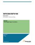
The 56800 core has two priority levels, as described in Table 6-10. Additional 56800 hardware
resources are shown in Figure 6-1. The 56800 Current Priority Level (CPL = I[1:0] in the SR)
indicates which interrupts are currently allowed. If CPL = 1, all interrupts are allowed, if
CPL = 3, only non-maskable interrupts are allowed. The 56800 family supplements this
mechanism with the CH[6:0] bits in the Interrupt Priority Register (IPR). These can be used to
arbitrate which of several active, maskable interrupts is to be asserted when CPL = 1. Each
on-chip interrupt source can be assigned to one of seven priority levels using the group priority
registers in the ITCN module. The CH[6:0] bit values must be managed by software, increasing
interrupt latency.
Table 6-10 56800 Interrupt Priority Levels
IPL
Description
Interrupt Sources
1
Non-maskable
Illegal Instruction, OnCE trap, HWS overflow, SWI
0
Maskable
On-chip peripherals, IRQA and IRQB
In contrast, the 56800E core has five priority levels (one is non-maskable), but no CH bits. Once
the interrupt assignments have been made, the hardware can run itself with no additional software
(beyond the ISRs) required.
Table 6-11 56800E Interrupt Priority Levels
IPL
Description
Priority
Highest
Nominal Interrupt Sources
3
Non-maskable
2
Maskable
On-chip peripherals, IRQA and IRQB, SWI #2 instruction, Enhanced OnCE
interrupts
1
Maskable
On-chip peripherals, IRQA and IRQB, SWI #1 instruction, Enhanced OnCE
interrupts
0
Maskable
On-chip peripherals, IRQA and IRQB, SWI #0 instruction
LP
Maskable
Lowest
Illegal Instruction, HWS overflow, SWI, Enhanced OnCE interrupts,
misaligned data acess
SWILP Instruction
Column four in Table 6-11 represents one possible way of allocating interrupt sources to
interrupt levels. In fact, the 56F8300/56F8100 devices’ interrupt controller allows more
flexibility in assigning core and EOnCE interrupts to specific levels.
Recall that in the 56800 family, the process for enabling interrupts is:
•
Clear any outstanding peripheral interrupt status bits (peripheral specific)
•
Enable interrupts of interest in individual peripheral register sets
56F807 to 56F8300/56F8100 Porting Guide, Rev. 0
20
Freescale Semiconductor
Preliminary
•
Enable and assign priorities to interrupts of interest in the appropriate Group Priority Register
(GPR) in the ITCN module
•
Enable interrupts and set IRQA and IRQB to level-sensitive or edge-sensitive in the Interrupt
Priority Register (IPR)
•
Enable interrupts in the Status Register (SR)
As discussed in Section 6.3.3, the interrupt table has been rearranged. This, plus the availablity
of only five priority levels, means that the organization of the 56F8300/56F8100 devices’
Interrupt Priority Registers are different (but similar) to the 56F807 Group Priority Registers.
Please consult the 56F8300/56F8100 documentation for details. In the 56800E family, the
process for enabling interrupts is:
•
Clear any outstanding peripheral interrupt status bits (peripheral-specific)
•
Enable interrupts of interest in individual peripheral register sets
•
Enable and assign priorities to interrupts of interest in the appropriate interrupt priority register
(IPRx) in the ITCN module. Note that a number of interrupt sources previously hardcoded on the
56F807 must be programmed into the 56F8300/56F8100 IPRx registers. These include IRQA,
IRQB and some of the EOnCE interrupts. A detailed mapping is shown in Table 6-13. See the
"Interrupt Vector Table Contents" section of the 56F8300/56F8100 Data Sheet for additional
information.
•
Enable interrupts and set IRQA or IRQB to level-sensitive or edge-sensitive choices in the ICTL
•
Select any two interrupt sources as fast interrupts and assign their ISR location using the ITCN Fast
Interrupt Match and Fast Interrupt Vector Address registers. Make sure these interrupts are
programmed as Level 2 interrupts.
•
Enable interrupts in the Status Register (SR)
Fast interrupts are not available on the 56F80x devices, and represent a major enhancement in
56F8300/56F8100 devices.
56F807 to 56F8300/56F8100 Porting Guide, Rev. 0
Freescale Semiconductor
Preliminary
21
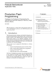
This register is not present in the 56F8300/56F8100 devices. Instead, see the ICTL (Figure 6-2).
56F807 Interrupt Priority Register
R
W
RESET:
15
14
13
12
11
10
9
CH0
CH1
CH2
CH3
CH4
CH5
CH6
0
0
0
0
0
0
0
8
7
0
6
0
5
4
3
2
1
0
IBL1
IBL0
IBINV
IAL1
IAL0
IAINV
0
0
0
0
0
0
0
= Unimplemented or Reserved
IBL1
IAL1
IBINV
IAINV
IRQA/IRQB
Trigger Mode
IBL0
IAL0
IRQA/IRQB
Enabled?
CH0
CH1
IPL
Enabled?
IPL
0
0
Low-level Sensitive
0
No
-
0
No
-
0
1
High-level Sensitive
1
Yes
0
1
Yes
0
1
0
Falling-edge Sensitive
1
1
Rising-edge Sensitive
The I[1:0] field is still present on 56F8300/56F8100 devices,
but all values are now in use. See Table 6-12 for details.
56F807 Status Register
R
W
RESET:
15
14
13
12
11
10
9
8
7
6
5
4
3
2
1
0
LF
P4
P3
P2
P1
P0
I1
I0
SZ
L
E
U
N
Z
V
C
0
0
0
0
0
0
0
0
0
0
0
0
0
0
0
0
Px
I1
I0
= Unimplemented or Reserved on the
56800 only (used on 56800E)
Exceptions Permitted
The 56F807 Group Priority Registers
are not shown . Their function has been
assumed by the 56F8300/56F8100
Interrupt Priority registers.
See
Table 6-13 for mapping from one to the
other.
Exceptions Masked
0
0
(Reserved)
(Reserved)
0
1
IPL 0,1
None
1
0
(Reserved)
(Reserved)
1
1
IPL1
IPL0
Figure 6-1 Interrupt-Related Registers for 56F807
15
R
INT
W
RESET:
0
14
13
12
11
10
IPIC
0
9
8
7
6
VAB
0
1
0
0
0
0
0
0
5
4
INT_
DIS
1
0
1
3
IRQB
STATE
2
IRQA
STATE
1
1
1
0
IRQB
EDG
IRQA
EDG
0
0
= Reserved or unused
Figure 6-2 56F834x / 56F835x / 56F836x Interrupt Control (ICTL) Register
56F807 to 56F8300/56F8100 Porting Guide, Rev. 0
22
Freescale Semiconductor
Preliminary
Table 6-12 56F800E Interrupt Mask Bit Settings
I1
I0
Exceptions Permitted
Exceptions Masked
0
0
IPL, 0, 1, 2, 3, LP
None
0
1
IPL 1, 2, 3
IPL 0
1
0
IPL 2, 3
IPL 0,1
1
1
IPL3
IPL 0, 1, 2
Table 6-13 56F807 GPR to 56F834x / 56F835x IPR Mapping1
56F807 ISR
Vector
Number
Peripheral
Interrupt Function
56F807 GPR
56F834x / 56F835x
IPR
63
LVI
Low Voltage Interrupts
GPR15[14:12]
IPR2[7:6]
62
PLL
PLL Interrupts
GPR15[10:8]
IPR2[9:8]
61
PWM A
PWM A Fault
GPR15[6:4]
IPR9[15:14]
60
PWM B
PWM B Fault
GPR15[2:0]
IPR9[13:12]
59
PWM A
Reload PWM A
GPR14[14:12]
IPR9[11:10]
58
PWM B
Reload PWM B
GPR14[10:8]
IPR9[9:8]
57
ADC A
ADC A Zero Crossing or Limit Error
GPR14[6:4]
IPR9[7:6]
56
ADC B
ADC B Zero Crossing or Limit Error
GPR14[2:0]
IPR9[5:4]
55
ADC A
ADC A Conversion Complete
GPR13[14:12]
IPR9[3:2]
54
ADC B
ADC B Conversion Complete
GPR13[10:8]
IPR9[1:0]
53
SCI 0
SCI 0 Receiver Full
GPR13[6:4]
IPR8[15:14]
52
SCI 0
SCI 0 Receiver Error
GPR13[2:0]
IPR8[13:12]
51
SCI 0
SCI 0 Transmitter Ready
GPR12[14:12]
IPR8[9:8]
50
SCI 0
SCI 0 Transmitter Complete
GPR12[10:8]
IPR8[7:6]
49
SCI 1
SCI 1 Receiver Full
GPR12[6:4]
IPR5[11:10]
48
SCI 1
SCI 1 Receiver Error
GPR12[2:0]
IPR5[9:8]
47
SCI 1
SCI 1 Transmitter Ready
GPR12[14:12]
IPR5[5:4]
46
SCI 1
SCI 1 Transmitter Complete
GPR11[10:8]
IPR5[3:2]
45
Timer A
Timer A ,Channel 3
GPR11[6:4]
IPR8[5:4]
44
Timer A
Timer A, Channel 2
GPR11[2:0]
IPR8[3:2]
43
Timer A
Timer A, Channel 1
GPR10[14:12]
IPR8[1:0]
42
Timer A
Timer A, Channel 0
GPR10[10:8]
IPR7[15:14]
41
Timer B
Timer B, Channel 3
GPR10[6:4]
IPR7[13:12]
40
Timer B
Timer B, Channel 2
GPR10[2:0]
IPR7[11:10]
39
Timer B
Timer B, Channel 1
GPR9[14:12]
IPR7[9:8]
56F807 to 56F8300/56F8100 Porting Guide, Rev. 0
Freescale Semiconductor
Preliminary
23
Table 6-13 56F807 GPR to 56F834x / 56F835x IPR Mapping1 (Continued)
56F807 ISR
Vector
Number
Peripheral
Interrupt Function
56F807 GPR
56F834x / 56F835x
IPR
38
Timer B
Timer B, Channel 0
GPR9[10:8]
IPR7[7:6]
37
Timer C
Timer C, Channel 3
GPR9[6:4]
IPR7[5:4]
36
Timer C
Timer C, Channel 2
GPR9[2:0]
IPR7[3:2]
35
Timer C
Timer C, Channel 1
GPR8[14:12]
IPR7[1:0]
34
Timer C
Timer C, Channel 0
GPR8[10:8]
IPR6[15:14]
33
Timer D
Timer D, Channel 3
GPR8[6:4]
IPR6[13:12]
32
Timer D
Timer D, Channel 2
GPR8[2:0]
IPR6[11:10]
31
Timer D
Timer D, Channel 1
GPR7[14:12]
IPR6[9:8]
30
Timer D
Timer D, Channel 0
GPR7[10:8]
IPR6[7:6]
29
Quad
Decoder 0
Quad Decoder 0 INDEX Pulse
GPR7[6:4]
IPR6[3:2]
28
Quad
Decoder 0
Quad Decoder 0 Home Switch or
Watchdog
GPR7[2:0]
IPR6[1:0]
27
Quad
Decoder 1
Quad Decoder 1 INDEX Pulse
GPR6[14:12]
IPR5[15:14]
26
Quad
Decoder 1
Quad Decoder 1 Home Switch or
Watchdog
GPR6[10:8]
IPR5[13:12]
25
SPI
SPI Receiver Full and/or Error
GPR6[6:4]
SPI0 - IPR4[15:14]
SPI1 - IPR4[11:10]
24
SPI
SPI Transmitter Empty
GPR6[2:0]
SPI0 - IPR5[1:0]
SPI1 - IPR4[13:12]
23
GPIO A
GPIO A
GPR5[14:12]
IPR4[5:4]
22
GPIO B
GPIO B
GPR5[10:8]
IPR4[3:2]
20
GPIO D
GPIO D
GPR5[2:0]
IPR3[15:14]
19
GPIO E
GPIO E
GPR4[14:12]
IPR3[13:12]
18
FPIU2
Program Flash Interface 2
GPR4[10:8]
HFM interrupt priority
levels are set using
IPR2[15:10]
17
MSCAN
MSCAN Wakeup
GPR4[6:4]
FlexCAN WKUP
IPR3[7:6]
16
MSCAN
MSCAN Error2
GPR4[2:0]
FlexCAN Error
IPR3[5:4]
15
MSCAN
MSCAN Receiver Full
GPR3[14:12]
FlexCAN MSG BUF
IPR3[9:8]
14
MSCAN
MSCAN Transmitter Ready
GPR3[10:8]
FlexCAN Bus-Off
IPR3[3:2]
56F807 to 56F8300/56F8100 Porting Guide, Rev. 0
24
Freescale Semiconductor
Preliminary
Table 6-13 56F807 GPR to 56F834x / 56F835x IPR Mapping1 (Continued)
56F807 ISR
Vector
Number
Peripheral
Interrupt Function
56F807 GPR
56F834x / 56F835x
IPR
13
DFIU
Data Flash Interface
GPR3[6:4]
12
PFIU1
Program Flash Interface 1
GPR3[2:0]
11
BFIU
Boot Flash Interface
GPR2[14:12]
9
core
IRQB
Hardwired
IPR2[3:2]
8
core
IRQA
Hardwired
IPR2[1:0]
6
core
OnCE Trap
Hardwired
IPR0[13:10] &
IPR1[5:0]
5
core
Hardware Stack Overflow
Hardwired
Hardwired
4
core
Software Interrupt (SWI)
Hardwired
Hardwired
3
core
Illegal Instruction Trap
Hardwired
Hardwired
1
core / COP
COP Timer Reset
Hardwired
Hardwired
core
External and Power-On Reset
Hardwired
Hardwired
0
HFM interrupt priority
levels are set using
IPR2[15:10]
1. 56F836x IPR mapping is different ,due to the addition of a second FlexCAN peripheral.
2. The MSCAN Error interrupt is generated when any of the following MSCAN interrupt sources is asserted: Overrun, Receiver
Warning, Transmitter Warning, Receiver Error Passive, Transmitter Error Passive and Bus Off.
6.5.2 Clock Generation
Registers whose function remains unchanged include PLLCR.
6.5.2.1 PLL Divide-By Register
The default value of the PLLDB field has changed from 0x10011 (19) to 0x11101 (29). The
56F8300 PLL runs at 4x the system speed; therefore, this translates to changing the instruction
rate from 40MIPS to 60MIPS.
6.5.2.2 PLL Status Register
The interrupt bits have been modified so that they cannot be set unless enabled. Previously, the
LOCI bit could be (and often was) triggered whenever the PLL was reprogrammed, regardless of
whether it was enabled or not. This has been improved in the 56F8300/56F8100 devices. LOCI
can be cleared by writing a one to it or by disabling the interrupt in the PLLCR.
56F807 to 56F8300/56F8100 Porting Guide, Rev. 0
Freescale Semiconductor
Preliminary
25
6.5.2.3 Clock Out Select Register
The Clock Out Select Register has been moved from the Clock Generation Module to the System
Integration Module. Bit 4 of the 56F807 CLKOSEL field has been relabeled CLKDIS and is
now at bit location 5, but the function remains the same. The set of clocks available for viewing
has necessarily changed. The CLKOSEL field has been extended by 1 bit to allow additional
choices.
The two chips are contrasted in Table 6-14.
Table 6-14 CLKOSEL Contrasted
CLKOSEL
(56F807)
{CLKDIS, CLKOSEL}
(56F8300/56F8100)
56F807
56F834x
56F835x
56F836x
1XXXX
1XXXXX
No Clock
No Clock
00000
000000
ZCLK (Default)
sys_clk (Default)
00001
000001
T0
56800E clock
00010
000010
T1
XRAM clock
00011
000011
T2
PFLASH odd clock
00100
000100
T3
PFLASH even clock
00101
000101
PHI0
BFLASH clock
00110
000110
PHI1
DFLASH clock
00111
00111
CTZN
oscillator output
01000
001000
CT301EN
Fout (from OCCS)
01001
001001
IPB Clock
IPB Clock
01010
001010
Feedback
Feedback
01011
001011
Prescaler
Prescaler
01100
001100
Fout
Postscaler
01101
001101
Fout/2
sys_clk_x2
01110
001110
Postscaler
sys_clk_div2
01111
001111
Postscaler
sys_clk_d
N/A
010000
N/A
ADCA clk
N/A
010001
N/A
ADCB clk
56F807 to 56F8300/56F8100 Porting Guide, Rev. 0
26
Freescale Semiconductor
Preliminary
The 56F8300/56F8100 devices have additionally added four bits to CLKOSR which provide
individual controls for bringing the oscillator clock, sys_clk_x2, sys_clk and prescaler clocks out
on GPIOB[7:4] respectively, should these pins not be required for use as GPIO.
6.5.2.4 Shutdown Register
This register can be used to shut off all system clocks in the event that a loss of reference clock
interrupt has occurred, indicating that the oscillator crystal has been damaged. This register was
not present on 56F807 device.
6.5.3 COP
6.5.3.1 COP Control Register (COPCTL)
The 56F8300/56F8100 devices add an extra bit to the COPCTL register to allow the COP to
utilize the peripheral clock instead of the oscillator clock as its time base. This is intended for
factory test use only. The default value of this bit yields operation equivalent to the 56F807.
6.5.3.2 COP Time Out Register
The clock prescaler has been changed from 16384 to 1024. To compensate, the time out field
(CT in 56F807, TIMEOUT in 56F8300/56F8100 devices) has been extended from 12 bits in the
56F807 to 16 bits in 56F8300/56F8100 devices. The default value has changed from 0x0FFF to
0xFFFF.
In the 56F807, the default time out period, assuming 40MHz, is:
(16384 X (0xFFF+1)) / 40E6 = 1.67 seconds
On the 56F8300 devices, the default time out period, assuming 60MHz, is:
(1024 X (0xFFFF + 1) / 60E6 = 1.12 seconds
6.5.3.3 COP Service Register (COPSRV) = COP Counter Register (COPCTR)
In the 56F807, COPSRV always reads as all zeros. In the 56F8300 devices, it has been renamed
COPCTR, and yields the current value of the COP counter.
6.5.4 GPIO
GPIO Ports C and F are new for 56F8300/56F8100 devices. On the 56F834x, 56F835x and
56F836x, the size of all ports except Port B has been increased to allow for more GPIO
capability.
56F807 to 56F8300/56F8100 Porting Guide, Rev. 0
Freescale Semiconductor
Preliminary
27
Table 6-15 GPIO Port Sizes
56F834x
Port
DSP56F807
56F835x
56F836x
A
8
14
B
8
8
C
—
11
D
8
13
E
8
14
F
—
16
6.5.4.1 PER for Port B
The peripheral enable bits for GPIO B[3:0] are 0 in the 56F807. On the 56F8300/56F8100
devices, they are a function of the EXTBOOT and EMI_MODE pins as the device exits reset.
See the Program Memory Map section in the individual device’s Data Sheet for details.
6.5.4.2 GPIO_x_RAWDATA Register
These registers are not present on the 56F807. They are an enhancement to the GPIO function
which allows the state of GPIO pins to be read at any time, even when those pins are not in GPIO
mode. This is a READONLY register.
6.5.4.3 GPIO_x_PPMODE Register
These registers are not present on the 56F807. They are an enhancement to the GPIO function
which allows the GPIO pins to operate in Push-Pull Mode or in Open Drain Mode. The default is
Push-Pull Mode, which is consistent with previous devices.
6.5.4.4 Pin Assignments
Table 6-16 illustrates GPIO pin assignments for the 56F807 and 56F8300/56F8100 devices. On
the 5656F807, peripherals muxed with GPIO took precedence at reset. This is also true on
56F8300/56F8100 devices, with the exception of GPIOB[3:0] (a function of boot mode) and
GPIOD[5:0]. In the latter case, GPIO are active at reset even though muxed with EMI chip
selects. This function is consistent with the 56F807, where those GPIO were not muxed. Shaded
areas in Table 6-16 indicate which function is active upon exiting reset in 56F8300/56F8100
devices.
56F807 to 56F8300/56F8100 Porting Guide, Rev. 0
28
Freescale Semiconductor
Preliminary
Table 6-16 56F8300/56F8100 GPIO Assignments
56F807
Peripheral
Function
56F834x
56F835x
56F836x
Peripheral Function
GPIO
Function
A8
A8
GPIOA0
A9
A9
GPIOA1
A10
A10
GPIOA2
A11
A11
GPIOA3
A12
A12
GPIOA4
A13
A13
GPIOA5
A14
A14
GPIOA6
A15
A15
GPIOA7
Not Defined
A8
GPIOA8
A1
GPIO A
A2
GPIOA10
A3
GPIOA11
A4
GPIOA12
A5
GPIOA13
A16
GPIOB0
A17
GPIOB1
A18
GPIOB2
A19
GPIOB3
A20
GPIOB4
A21
GPIOB5
A22
GPIOB6
A23
GPIOB7
No
Alternate
Function
Notes
56F834x / 56F835x / 56F836x Boot determined
from EXTBOOT & EMI_MODE pin values during
reset
56F807 to 56F8300/56F8100 Porting Guide, Rev. 0
Freescale Semiconductor
Preliminary
29
Table 6-16 56F8300/56F8100 GPIO Assignments (Continued)
56F807
Peripheral
Function
Not
Applicable —
Was previously
Timer B without
GPIO
56F834x
56F835x
56F836x
Peripheral Function
GPIO
Function
PHASEA1 / TB0 / SS1
GPIOC0
PHASEB1 / TB1 / SCLK1
GPIOC1
INDEX1 / TB2 / MISO1
GPIOC2
HOME1 / TB3 / MOSI1
GPIOC3
PHASEA0 / TA0
GPIOC4
PHASEB0 TA1
GPIOC5
INDEX0 / TA2
GPIOC6
HOME0 / TA3
GPIOC7
ISA0
GPIOC8
ISA1
GPIOC9
ISA2
GPIOC10
CS2
GPIOD0
CS3
GPIOD1
CS4
GPIOD2
CS5
GPIOD3
CS6
GPIOD4
CS7
GPIOD5
TXD1
TXD1
GPIOD6
RXD1
RXD1
GPIOD7
Not Defined
PS / CS0
GPIOD8
DS / CS1
GPIOD9
ISB0
GPIOD10
ISB1
GPIOD11
ISB2
GPIOD12
TXD0
GPIOE0
Not Defined
No
Alternate Function
TXD0
Notes
There was no GPIO c port on DSP56F807
These pins were dedicated GPIO on 56F807. On
56F8300/56F8100, GPIO is active upon exiting
reset to retain compatibility with 56F807.
56F807 to 56F8300/56F8100 Porting Guide, Rev. 0
30
Freescale Semiconductor
Preliminary
Table 6-16 56F8300/56F8100 GPIO Assignments (Continued)
56F807
Peripheral
Function
56F834x
56F835x
56F836x
Peripheral Function
GPIO
Function
RXD0
RXD0
GPIOE1
A6
A6
GPIOE2
A7
A7
GPIOE3
SCLK
SCLK
GPIOE4
MOSI
MOSI0
GPIOE5
MISO
MISO0
GPIOE6
SS
SS0
GPIOE7
Not Defined
TC0
GPIOE8
TC1
GPIOE9
TD0
GPIOE10
TD1
GPIOE11
TD2
GPIOE12
TD3
GPIOE13
D7
GPIOF0
D8
GPIOF1
D9
GPIOF2
D10
GPIOF3
D11
GPIOF4
D12
GPIOF5
D13
GPIOF6
D14
GPIOF7
Not Defined
Notes
56F807 to 56F8300/56F8100 Porting Guide, Rev. 0
Freescale Semiconductor
Preliminary
31
Table 6-16 56F8300/56F8100 GPIO Assignments (Continued)
56F807
Peripheral
Function
Not Defined
56F834x
56F835x
56F836x
Peripheral Function
GPIO
Function
D15
GPIOF8
D0
GPIOF9
D1
GPIOF10
D2
GPIOF11
D3
GPIOF12
D4
GPIOF13
D5
GPIOF14
D6
GPIOF15
Notes
6.5.5 Power Supervisor
In the 56F807, the power supervisor was considered part of the system integration module. In the
56F8300/56F8100 devices, this function has been decoupled and enhanced.
Low-voltage interrupt enables have been moved from the 56F807 System Control Register
(SYS_CNTL) to the 56F8300/56F8100 Power Supervisor Control Register, as shown here.
56F807 to 56F8300/56F8100 Porting Guide, Rev. 0
32
Freescale Semiconductor
Preliminary
56F807 System Control Register = SYS_BASE + $0
R
W
RESET:
15
0
14
0
13
0
12
0
0
0
0
0
11
TMRPD
0
10
CTRLPD
0
9
ADR
PD
0
8
DATA
PD
0
7
0
6
0
5
0
0
0
0
4
3
2
BOOTLVIE27 LVIE22
MAP
0
0
0
1
0
PD
RPD
0
0
= Unimplemented or Reserved
56F834x, 56F835x and 56F836x Power Supervisor Control Register = LVI_BASE + $0
R
W
RESET:
15
0
14
0
13
0
12
0
11
0
10
0
9
0
8
0
7
0
6
0
5
0
4
0
3
0
2
0
0
0
0
0
0
0
0
0
0
0
0
0
0
0
1
0
LVIE27 LVIE22
0
0
= Unimplemented or Reserved
Figure 6-3 Low-Voltage Interrupt Enables
The actual status and interrupt bits themselves have been moved from the SYS_STS register to the Power
Supervisor Status Register; see Figure 6-4. In the 56F807, the status pins were "sticky", and to query
the current voltage status, it was necessary to clear those bits and reread them. In the 56F8300/56F8100,
there are sticky and non-sticky versions of the same bits, all of which may be accessed with a single read
operation.
56F807 System Status Register = SYS_BASE + $1
R
W
RESET:
15
0
14
0
13
0
12
0
11
0
10
0
9
0
8
0
7
0
6
0
5
0
4
COPR
3
EXTR
2
POR
0
0
0
0
0
0
0
0
0
0
0
0
0
0
1
0
LVIS27
LVIS22
0
0
= Unimplemented or Reserved
56F8300/56F8100 Power Supervisor Status Register = LVI_BASE + $1
R
W
RESET:
15
0
14
0
13
0
12
0
11
0
10
0
9
0
8
0
7
0
6
0
5
0
0
0
0
0
0
0
0
0
0
0
0
4
3
2
LVI
LVIS27S
LVIS22S
0
0
0
1
0
LVIS27 LVIS22
0
0
= Unimplemented or Reserved
These are the non-sticky versions
Figure 6-4 Power Supervisor Status Bits
56F807 to 56F8300/56F8100 Porting Guide, Rev. 0
Freescale Semiconductor
Preliminary
33
6.5.6 CAN Module
The 56F8300/56F8100 devices contain Freescale’s FlexCAN interface instead of the MSCAN.
MSCAN represents a "basic CAN" implementation, while FlexCAN represents a "full CAN"
implementation. The two modules are not software-compatible. CAN communication routines
must be redesigned for FlexCAN.
The FlexCAN module will NOT have the option of using the oscillator time clock (the PLL clock
should be accurate enough for all operation1).
6.5.7 Analog-to-Digital Converters
The 56F807 and 56F8300/56F8100 devices contain (2) dual ADC converters. On the 56F807,
each dual has its own single-pin voltage reference circuit. On 56F8300/56F8100 devices, a
single 6-pin circuit services both duals. This has no effect on software executing on the device.
The DIV field in ADC Control Register 2 (ADCR2) has been increased from four to five bits and
its reset value changed from 0111 to 00101. The later will yield a conversion rate of 5MHz at a
60MHz system bus rate (recommended).
The 56F8300/56F8100 devices add the ADC Power Control Register (ADCPOWER). This
provides intelligent power savings features for the ADCs, which are one of the most
power-hungry on-chip features. The reset value of this register is such that the ADCs are
powered up upon reset, consistent with operation in the 56F807.
All other ADC registers map across unchanged from the 56F807 to the 56F8300/56F8100
devices.
To obtain better accuracy, the 56F8300/56F8100 devices have also added the ADC_CAL register
to facilitate on-the-fly calibration of the ADC. This register is not part of the 56F807 design.
When this register was added, the two test bits in the ADSDIS register were removed.
6.5.8 Internal Temperature Sensor
The 56F8300 devices have added an internal temperature sensor module. The voltage output of
this module is bonded to the TEMP_SENSE pin. Wiring this pin to one of the analog inputs (at
the board level) allows the ADC to monitor the IC’s internal temperature.
1.Accumulated error should be less than or equal to +/- 0.5 PLL cycle plus any inaccuracies due to the crystal.
56F807 to 56F8300/56F8100 Porting Guide, Rev. 0
34
Freescale Semiconductor
Preliminary
6.5.9 External Memory Interface
In the 56F80x family, which includes the 56F807, the user could control wait states for external
data memory separately from external Program memory and could also control output drive
characteristics of the port signals. These controls were lumped into the Bus Control Register
(BCR), which was located in the memory map section devoted to core configuration registers.
In the 56F8300/56F8100, the external memory interface has been completely redesigned and
supports multiple Chip Selects (CS). Each CS can be configured as either Program space, Data
space, or both. Timing can be individually controlled for each CS. This provides for optimal
performance from the external memory interface. Each CS can specify unique wait states for read
and write access, as well as setting set-up and hold wait states if desired. To accomplish this,
three registers are allocated for each CS defined. The BCR register has been moved into the EMI
module and is now used only to specify default timing if access is made to an area of the memory
map not covered by a CS.
The fields for specifying wait states have increased from 4 to 5 bits. The new set-up and hold wait
states fields are 2 bits each. Also, in the 56F807, wait states had to be an integer multiple of four.
That restriction has been removed on the 56F8300/56F8100 devices. Note that the default
number of wait states at reset has been changed to 11, which allows operation with a 180ns
device.
The reset value of the BCR has changed since the register fields have been redefined. The BCR
no longer distinguishes between Program and Data space accesses, since without a CS, there is no
external indication of which memory space is being referenced.
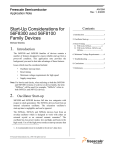
As shown in Figure 6-5, the DRV bit has also moved from bit location 9 to bit location 15. It is
recommended that the DRV bit be set to 1, except in situations in which multiple processors with
similar bus interfaces share a common external memory interface.
56F807 to 56F8300/56F8100 Porting Guide, Rev. 0
Freescale Semiconductor
Preliminary
35
56F807 Bus Control Register
R
W
RESET:
15
0
14
0
13
0
12
0
11
0
10
0
0
0
0
0
0
0
9
DRV
0
8
0
0
7
6
5
4
Wait State Field for External X
Memory
1
1
1
1
3
2
1
0
Wait State Field for External P
Memory
1
1
1
1
= Unimplemented or Reserved
56F8300/56F8100 Bus Control Register
15
R
W
RESET:
14
DRV
0
13
12
BMDAR[2:0]
0
0
0
11
0
10
0
9
0
0
0
8
7
6
5
4
3
BWWS[4:0]
1
0
2
1
0
1
1
BRWS[4:0]
1
1
0
1
0
= Unimplemented or Reserved
Figure 6-5 Bus Control Register Mapping
The 56F8300/56F8100 device’s EMI module is signficantly more advanced than the EMI found
on the 56F807 device. Depending on the package, there are eight chip selects available, which
may be programmed in numerous ways. On 56F8300/56F8100, CS0 and CS1 are programmed
to emulate the 56F807 PS and DS data strobes at reset. If the EMI_MODE pin is set to 0 and
EXBOOT is set to 1 at reset, then the 56F8300/56F8100 EMI will emulate the 56F807 EMI in
external boot mode, subject to the following change:
On the 56F8300/56F8100, the RD signal assertion is delayed 1/4 cycle from where it occurred on
the 56F807, so that it can be used as an output enable signal (to avoid external bus contention).
6.5.10 SCI
This is the same module as implemented on the 56F807. Because the bus frequency has been
increased to 60MHz max, it will be necessary to change the value of the SCI Baud Rate Register
(SCIBR) to adjust. Table 6-17 and Table 6-18 show baud rate settings for the SCI at bus speeds
of 40MHz and 60MHz. These correspond to the maximum bus speeds for the 56F807 and the
56F8300, respectively. This demonstrates that code previously operating at 9600 baud on the
56F807 (at 40MHz) set the SBR to 260. This must be changed to SBR = 391 for the 56F8300
devices to maintain the same bit rate (at a processor speed of 60MHz).
56F807 to 56F8300/56F8100 Porting Guide, Rev. 0
36
Freescale Semiconductor
Preliminary
Table 6-17 Example Baud Rates (Module Clock = 40MHz)
SBR
Bits
Receiver Clock
(Hz)
Transmitter Clock
(Hz)
Target Baud
Rate
Error
(%)
65
615384.6
38461.5
38,400
0.16
130
307692.3
19230.8
19,200
0.16
260
153846.1
9615.4
9600
0.16
521
76775.4
4798.5
4800
0.03
1042
38387.7
2399.2
2400
0.03
2083
19203.1
1200.2
1200
0.02
4167
9599.2
600.0
600
0.01
Table 6-18 Example Baud Rates (Module Clock = 60MHz)
SBR
Bits
Receiver Clock
(Hz)
Transmitter Clock
(Hz)
Target Baud
Rate
Error
(%)
98
612244.9
38265.3
38,400
0.35
195
307692.3
19230.8
19,200
0.16
391
153452.7
9590.8
9600
0.10
781
76824.6
4801.5
4800
0.03
1562
38412.3
2400.8
2400
0.03
3125
19200.0
1200.0
1200
0.00
6250
9600.0
600.0
600
0.00
6.5.11 SPI
In the SPI Status and Control Register (SPSCR), the SPR[1:0] field was increased to SPR[2:0]
(allowing more baud rate flexibility) and the bits in the register were rearranged as shown in
Figure 6-6.
56F807 to 56F8300/56F8100 Porting Guide, Rev. 0
Freescale Semiconductor
Preliminary
37
56F807 SPI Status and Control Register (SPSCR)
R
W
RESET:
15
0
0
14
DSO
13
SPRF
0
0
12
11
10
9
8
7
6
5
4
3
2
OVRF MODF SPTE MODSPMERRIE
SPR1 SPR0 SPRIE
CPOL CPHA
FEN
STR
0
0
0
0
0
0
0
0
1
0
1
1
0
SPE
SPTIE
0
0
= Unimplemented or Reserved
56F8300/56F8100 SPI Status and Control Register (SPSCR)
15
R
W
RESET:
14
13
SPR[2:0]
0
1
1
12
11
10
9
8
7
6
MODSPMDSO ERRIE
SPRIE
CPOL CPHA
FEN
STR
0
0
0
0
1
0
1
5
4
SPE
SPTIE
0
0
3
2
1
0
SPRF OVRF MODF SPTE
0
0
0
1
= Unimplemented or Reserved
Figure 6-6 SPI Status and Control Register Mapping
As shown in Table 6-19, the change to 60MHz for a top speed in 56F8300 devices makes it
difficult to maintain consistent baud rates between the two devices. Fortunately, the SPI protocol
is a synchronous one, in which CLK is supplied with data.
Table 6-19 SPI Baud Rate Selection
/
56F835x /
56F807 Divisor
/
56F835x /
56F834x
56F807
SPR[1:0]
56F836x
SPR[2:0]
56F834x
56F836x
Divisor
56F834x/
56F807 Baud
Rate at 40MHz
IPBus
56F835x/
56F836x
Baud Rate at
60MHz IPBus
00
000
2
2
20 MBS
30MBS
01
001
8
4
5 MBS
15MBS
10
010
16
8
2.5 MBS
7.5MBS
11
011
32
16
1.25 MBS
3.75MBS
Not Applicable
100
Not Applicable
32
Not Applicable
1875KBS
101
64
937.5KBS
110
128
468750
111
256
234375
56F807 to 56F8300/56F8100 Porting Guide, Rev. 0
38
Freescale Semiconductor
Preliminary
The SPI Data Size and Control Register (SPDSR) adds a Wired-OR Mode bit in the
56F8300/56F8100 devices, but is upwards compatible from the 56F807.
The SPI Data Receive Register (SPDRR) and SPI Data Transmit Register (SPDTR) are identical
on both 56F807 and 56F8300/56F8100 parts.
There are a number of errata present in the 56F807 implementation of the SPI. These have been
corrected in the 56F8300/56F8100 devices.
6.5.12 Quad Timer
The 56F8300/56F8100 families use the same timer module as the 56F807; all register definitions
from the 56F807 remain unchanged. In the 56F8300/56F8100 families, the timer has been
enhanced with the addition of the Compare Preload Registers (CMPLD1 and CMPLD2) and the
associated Compare Status and Control Register (COMSCR). These new registers ease the
software timing constraints associated with CMP1and CMP2 register updates.
Because the IPBus clock frequency is 50% faster in 56F8300 devices relative to the 56F807
device, timer register values must be adjusted to account for the change.
The 56F807 offers four Timers, A through D. The 56F8300 devices have muxed Timer B/DEC 1
with a second SPI. If the SPI is used, the timer cannot be referenced externally.
The 56F8100 has only Timer A.
6.5.13 Quadrature Decoder
This is the same module used on the 56F807.
The 56F807 has two Quadrature Decoders, one of which is associated with Timer B. The
56F8300/56F8100 devices have muxed Timer B/DEC 1 with a second SPI. If the SPI is used,
DEC 1 cannot be used.
6.5.14 PWM Module
This is based upon the 56F807 PWM module, but some enhancements have been made for
swapping and masking functions. The Debug/Wait mode operation has been modified and the
dead time register (PMDEADTM) has been increased from 8 to 12 bits.
Registers which map directly between implementations are: PMCTL, PMFCTL, PMFSA,
PMOUT, PWMCM, PWMVAL0-5, PMDISMAP1-2 and PMPORT.
56F807 to 56F8300/56F8100 Porting Guide, Rev. 0
Freescale Semiconductor
Preliminary
39
Bit 13 of the PWM Configure Register (PMCFG) was reserved in the 56F807. On
56F8300/56F8100 devices, it is WAIT_EN, which can be used to enable/disable PWM operation
during Wait mode. Bit 14 of the same register, previously reserved on the 56F807, is now
DBG_EN. This bit enable/disable PWM operation during Debug mode. Both WAIT_EN and
DBG_EN default to zero (PWM disabled in these modes), which is considered the most
conservative setting.
Bit 15 of the PWM Channel Control Register (PMCCR) has been changed from RESERVED on
the 56F807 to the nBX bit on the 56F8300/56F8100 devices. It enables an alternate circuit
configuration for mask & swap operations. The default value of zero provides operation
consistent with the 56F807.
A new register, the PWM Internal Correction Control Register (PMICCR), was added on the
56F8300/56F8100 devices. This register allows for better control of dead time correction.
See the PWM section in the 56F8300 Peripheral User Manual for details of the changes
outlined in this section.
6.5.15 Flash Interface Unit
This is a new module in the 56F8300/56F8100 families. It is NOT upward-compatible from the
56F807.
6.5.16 System Integration Functions
The System Integration Module (SIM) contains much of the "glue" that ties any hybrid controller
together. The nature of the "glue" logic tends to be somewhat chip-specific. This implies that
SIM registers tend to be non-portable. That said, many of the 56F807 SIM features ARE present
on 56F8300/56F8100 devices. The mapping of SIM functions from the 56F807 to
56F8300/56F8100 is detailed in the following sections.
Note that COP functionality, specified in the 56F807 SIM chapter, was previously discussed in
Section 6.5.3. Similarly, power supervisor functions were discussed in Section 6.5.5.
The memory maps for the 56F807 and 56F8300/56F8100 SIM modules are quite different, as
shown in Table 6-20.
56F807 to 56F8300/56F8100 Porting Guide, Rev. 0
40
Freescale Semiconductor
Preliminary
Table 6-20 56F807 and 56F8300/56F8100 SIM Memory Maps
Address Offset From Base
56F807
$1C
TST_REG4
$1B
TST_REG3
$1A
TST_REG2
$19
TST_REG1
$18
TST_REG0
56F834x / 56F835x / 56F836x
$0F
SIM_PCE2 (56F836x only)
$0E
SIM_ISALL
$0D
SIM_ISALH
$0C
SIM_PCE
$0B
SIM_GPS
$0A
SIM_CLKOSR
$09
Reserved
$08
SIM_PUDR
$07
LSH_ID
SIM_LSH_ID
$06
MSH_ID
SIM_MSH_ID
$05
SIM_SCR3
$04
SIM_SCR2
$03
SIM_SCR1
$02
SIM_SCR0
$01
SYS_STS
SIM_RSTSTS
$00
SYS_CNTL
SIM_CONTROL
6.5.16.1 System Control Register
Elements of the 56F807 SYS_CNTL register map to the 56F8300/56F8100 SIM Pullup Control
Register and to the 56F8300/56F8100 SIM Control Register. The 56F807 has one-time and
reprogrammable controls for disabling Stop/Wait functions. The 56F8300/56F8100 have
expanded on this by allowing separate controls for Stop and Wait individually. Therefore, the
PD and RPD bits in the 56F807 map into four bits in the 56F8300/56F8100 devices.
Pull-up enable bits have been moved into their own register, and additional granularity has been
provided. The TMRPD, ADRPD and DATAPD bits from the 56F807 SYS_CNTL register have
56F807 to 56F8300/56F8100 Porting Guide, Rev. 0
Freescale Semiconductor
Preliminary
41
been removed from the 56F8300/56F8100, since all associated pins have been muxed with GPIO
capabilities and the GPIO control registers therefore handle pull-up enabling.
The 56F8300/56F8100 boot modes are a bit different than those on the 56F807, and the
BOOTMAP bit has been eliminated, as the OMR MA & MB bits serve that function in the
56F8300/56F8100 devices. Finally, the low-voltage interrupt enable bits have been moved into
the power supervisor module register set.
56F8300/56F8100 SIM Control Register
Base + $0
15
14
13
12
11
10
9
8
7
Read
0
0
0
0
0
0
0
0
0
0
0
0
0
0
0
0
0
0
6
4
3
EMI_ ONCE SW
MODE EBL RST
Write
RESET
5
0
0
0
2
1
0
STOP_
DISABLE
WAIT_
DISABLE
0
0
0
0
See Section 6.5.5
BOOTMAP function covered via OMR MA &
MB bits in 56F8300/56F8100. For details, see the
Program Memory Map section in the Data Sheet
for the specific device being implemented.
56F807 System Control Register (SYS_CNTL) = SYS_BASE + $0
R
W
RESET:
15
0
14
0
13
0
12
0
0
0
0
0
11
10
9
8
TMR- CTRL- ADRP DATAPD
PD
D
PD
0
0
0
0
7
0
6
0
5
0
0
0
0
4
3
2
BOOT
LVIE27 LVIE22
MAP
0
0
0
1
0
PD
RPD
0
0
= Unimplemented or Reserved
56F8300/56F8100 SIM Pull-up Disable Register
Base + $8
15
Read
0
Write
RESET
0
14
13
12
11
10
9
8
7
PWMA1
CAN
EMI_
MODE
RESET
IRQ
XBOOT
PWMB
PWMA0
0
0
0
0
0
0
0
0
6
0
0
5
CTRL
0
4
0
0
3
JTAG
0
2
1
0
0
0
0
0
0
0
Figure 6-7 56F807 SYS_CNTL Register Mappings
6.5.16.2 System Status Register
The low-voltage interrupt bits in the 56F807 SYS_STS register have been moved to the power
supervisor. See Section 6.5.5 for details.
56F807 to 56F8300/56F8100 Porting Guide, Rev. 0
42
Freescale Semiconductor
Preliminary
The COPR, EXTR & POR bits have been moved to the same locations in the 56F8300/56F8100
devices’ SIM_RSTSTS register.
56F807 System Status Register
R
W
RESET:
15
0
14
0
13
0
12
0
11
0
10
0
9
0
8
0
7
0
6
0
5
0
0
0
0
0
0
0
0
0
0
0
0
4
3
COPR EXTR
0
2
POR
0
0
1
0
LVIS2 LVIS2
7
2
0
0
= Unimplemented or Reserved
56F8300/56F8100 Reset Status Register
R
W
RESET:
15
0
14
0
13
0
12
0
11
0
10
0
9
0
8
0
7
0
6
0
0
0
0
0
0
0
0
0
0
0
5
4
3
SWR COPR EXTR
0
0
0
2
1
0
0
0
POR
0
= Unimplemented or Reserved
Figure 6-8 SYS_STS Mapping to SIM_RSTSTS
6.5.16.3 JTAG ID
The 56F807 and 56F8300/56F8100 devices all provide memory-mapped registers containing the
chip’s JTAG ID. These are contrasted in Table 6-21.
Table 6-21 56F807 vs. 56F8300/56F8100 JTAG IDs
56F807 Register Name
56F834x / 56F835x /
56F836x Register Name
56F807
Value
56F834x
Value
56F835x
Value
56F836x
Value
$11F41
$01F4
$01D6
$601D
$D01D
MSH_ID
SIM_MSH_ID
$01F2
LSH_ID
SIM_LSH_ID
$701D
$401D
1. Value for Rev. C and later 56F834x devices; value for Rev. A and B 56F834x devices is $01F4.
6.5.16.4 Test Registers
The 56F807 Test Registers 0-4 (TST_REG0 through TST_REG4) are never reset during normal
operation, and were originally intended primarily for factory test scratchpad use. The
56F8300/56F8100 devices offer SIM Software Control Registers 0-3 (SIM_SCR0 through
SIM_SCR3). These are reset only upon power up.
56F807 to 56F8300/56F8100 Porting Guide, Rev. 0
Freescale Semiconductor
Preliminary
43
6.5.17 Operating Mode Register
The MA bit continues to reflect the state of the EXTBOOT pin upon exiting reset. The MB bit
shows the secured state of the Flash when the device was reset.
56F807 to 56F8300/56F8100 Porting Guide, Rev. 0
44
Freescale Semiconductor
Preliminary
56F807 to 56F8300/56F8100 Porting Guide, Rev. 0
Freescale Semiconductor
Preliminary
45
56F807 to 56F8300/56F8100 Porting Guide, Rev. 0
46
Freescale Semiconductor
Preliminary
56F807 to 56F8300/56F8100 Porting Guide, Rev. 0
Freescale Semiconductor
Preliminary
47
How to Reach Us:
Home Page:
www.freescale.com
E-mail:
[email protected]
USA/Europe or Locations Not Listed:
Freescale Semiconductor
Technical Information Center, CH370
1300 N. Alma School Road
Chandler, Arizona 85224
+1-800-521-6274 or +1-480-768-2130
[email protected]
Europe, Middle East, and Africa:
Freescale Halbleiter Deutschland GmbH
Technical Information Center
Schatzbogen 7
81829 Muenchen, Germany
+44 1296 380 456 (English)
+46 8 52200080 (English)
+49 89 92103 559 (German)
+33 1 69 35 48 48 (French)
[email protected]
Japan:
Freescale Semiconductor Japan Ltd.
Headquarters
ARCO Tower 15F
1-8-1, Shimo-Meguro, Meguro-ku,
Tokyo 153-0064, Japan
0120 191014 or +81 3 5437 9125
[email protected]
Asia/Pacific:
Freescale Semiconductor Hong Kong Ltd.
Technical Information Center
2 Dai King Street
Tai Po Industrial Estate
Tai Po, N.T., Hong Kong
+800 2666 8080
[email protected]
For Literature Requests Only:
Freescale Semiconductor Literature Distribution Center
P.O. Box 5405
Denver, Colorado 80217
1-800-441-2447 or 303-675-2140
Fax: 303-675-2150
[email protected]
Information in this document is provided solely to enable system and
software implementers to use Freescale Semiconductor products. There are
no express or implied copyright licenses granted hereunder to design or
fabricate any integrated circuits or integrated circuits based on the
information in this document.
Freescale Semiconductor reserves the right to make changes without further
notice to any products herein. Freescale Semiconductor makes no warranty,
representation or guarantee regarding the suitability of its products for any
particular purpose, nor does Freescale Semiconductor assume any liability
arising out of the application or use of any product or circuit, and specifically
disclaims any and all liability, including without limitation consequential or
incidental damages. “Typical” parameters that may be provided in Freescale
Semiconductor data sheets and/or specifications can and do vary in different
applications and actual performance may vary over time. All operating
parameters, including “Typicals”, must be validated for each customer
application by customer’s technical experts. Freescale Semiconductor does
not convey any license under its patent rights nor the rights of others.
Freescale Semiconductor products are not designed, intended, or authorized
for use as components in systems intended for surgical implant into the body,
or other applications intended to support or sustain life, or for any other
application in which the failure of the Freescale Semiconductor product could
create a situation where personal injury or death may occur. Should Buyer
purchase or use Freescale Semiconductor products for any such unintended
or unauthorized application, Buyer shall indemnify and hold Freescale
Semiconductor and its officers, employees, subsidiaries, affiliates, and
distributors harmless against all claims, costs, damages, and expenses, and
reasonable attorney fees arising out of, directly or indirectly, any claim of
personal injury or death associated with such unintended or unauthorized
use, even if such claim alleges that Freescale Semiconductor was negligent
regarding the design or manufacture of the part.
Freescale™ and the Freescale logo are trademarks of Freescale Semiconductor,
Inc. All other product or service names are the property of their respective owners.
This product incorporates SuperFlash® technology licensed from SST.
© Freescale Semiconductor, Inc. 2004. All rights reserved.
8300PUG
Rev. 0
12/2004