1
N U F L O TM
2-inch Gas Flowmeter
User Manual
Manual No. 9A-100079591, Rev. 01
© 2009 Cameron International Corporation ("Cameron"). All information contained in this
publication is confidential and proprietary property of Cameron. Any reproduction or use of
these instructions, drawings, or photographs without the express written permission of an officer of Cameron is forbidden.
All Rights Reserved.
Printed in the United States of America.
Manual No. 9A-100079591, Rev. 01
September 2009
Table of Contents
Section 1—Introduction.................................................................................. 5
Operating Principles............................................................................................................5
Specifications.......................................................................................................................6
Section 2—Setup and Calibration................................................................ 11
Installation........................................................................................................................... 11
Calibration of Electronic Readout Equipment................................................................. 11
Absolute Pressure and Temperature.......................................................................... 12
Calculating Gas Volume in Actual Cubic Feet............................................................ 12
Calculating Gas Volume in Standard Cubic Feet....................................................... 13
Determining the Divisor for Readout in Standard Cubic Feet.................................. 13
Effects of Supercompressibility..................................................................................14
Calibrating Equipment for Readout in Standard Cubic Feet Per Unit of Time . ..... 14
Effects of Fluctuating Temperatures........................................................................... 15
Effects of Fluctuating Pressures.................................................................................16
Section 3—Maintenance .............................................................................. 21
Removing and Replacing Cartridges...............................................................................21
Flowmeter Assemblies.......................................................................................................22
Spare Parts.........................................................................................................................22
Accessories........................................................................................................................22
September 2009
iii
iv
September 2009
Section 1
Introduction
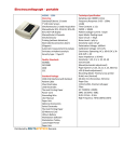
The NuFlo 2-in. Gas Flowmeter is a turbine flowmeter, housed inside an insert element that is placed between
two raised-face flanges. Continuous stud bolts draw the flanges together against the housing element, and
gaskets on the face of the flanges and meter body help ensure a competent seal. Bolts, nuts, and gaskets are
available as part of an optional hardware installation kit.
All internal components—the rotor and shaft assembly, bearings, and setscrews—are contained within a cartridge inside the meter. Three different cartridges are available to accommodate high, standard, and low flow
ranges (see Figs. 1.2 through 1.4, pages 3 through 5).
An electromagnetic pickup screwed into the receptacle on the side of the meter produces the output signal.
Figure 1.1—Flowmeter components
Operating Principles
The gas to be measured is flowed through the meter. As the gas passes the rotor, it impinges against the
pitched rotor blade, causing the rotor to spin at a speed directly proportional to the velocity of the gas stream.
As the rotor spins, its blades interrupt the magnetic field set up by the pickup. This interruption induces a
voltage in the coil of the pickup. The readout instrument senses this voltage pulse and converts it into a usable
form that indicates gas volume.
September 2009
5
Specifications
Size
2-in. (50.8 mm)
End Connections
Flowmeter installs between two raised face
flanges
Working Pressure
0 to 2220 psig (15,306 kPa)
Nominal Calibration Factor
Low Range
325 p/ACF (16600 p/m3)
Standard Range
125 p/ACF (4415 p/m3)
High Range
70 p/ACF (2472 p/m3)
Output Frequency
5 to 320 Hz over rated range
Output Voltage
30 mV peak to peak at 5 Hz, 900 mV peak to peak
at 320 Hz
Pressure Drop
Less than 1-in. (24.5 mm) water column at maximum rated flow
Linearity
+/- 2% of reading
Repeatability
+/- 0.5% of reading
Temperature
0º to 225ºF (-18º to 107ºC)
Pickup Connector
Mates with AN3106A-10SL-4P
Conduit Connection
1-in. (25.4 mm)
Pressure Tap
1/8-in. NPT (3.2 mm)
Compliances
CSA Certified Hazardous locations Class I,
Groups A, B, C, D, Div. 1, ANSI 12.27.01-2003
Single Seal
Certified by Cameron in compliance with prequalified materials of NACE MR0175/ISO 15156.
This certification does not imply or warrant the
application of the product in compliance with
NACE MR0175/ISO 15156 service conditions in
which the customer/user installs the product.
6
September 2009
(SCFM)
MCFD
CU. M/DAY
(69444.4) 100000
2832000
(34722.2) 50000
1416000
(13888.9) 20000
566400
(6944.4)
10000
283200
(3472.2)
5000
141600
(1388.9)
2000
56640
(694.4)
1000
28320
(347.2)
500
14160
(138.9)
200
5664
(69.4)
100
2832
(34.7)
50
1416
(13.9)
20
566.4
(6.9)
10
283.2
(3.5)
5
141.6
(1.4)
2
56.6
(0.7)
1
1
(6.9)
28.3
2
(13.8)
5
(34.5)
10
(69)
20
(138)
50
(345)
100
(690)
200
(1380)
500
(3450)
1000
(6900)
2000
(13800)
FLOWING PRESSURE, PSIG (kPa)
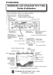
Flow rate ranges are based on 0.6 Sp. Gr. gas.
To determine capacity for other gases, use:
Q(g) = Q(.6)
Figure 1.2—High gas flow range
September 2009
0.6
G
where
Q(.6)= Flow rate on graph at operating pressure
G = Sp. Gr. of other gas
Q(g) = Flow rate for other gas
7
(SCFM)
MCFD
CU. M/DAY
(69444.4) 100000
2832000
(34722.2) 50000
1416000
(13888.9) 20000
566400
(6944.4)
10000
283200
(3472.2)
5000
141600
(1388.9)
2000
56640
(694.4)
1000
28320
(347.2)
500
14160
(138.9)
200
5664
(69.4)
100
2832
(34.7)
50
1416
(13.9)
20
566.4
(6.9)
10
283.2
(3.5)
5
141.6
(1.4)
2
56.6
(0.7)
1
1
(6.9)
28.3
2
(13.8)
5
(34.5)
10
(69)
20
(138)
50
(345)
100
(690)
200
(1380)
500
(3450)
1000
(6900)
2000
(13800)
FLOWING PRESSURE, PSIG (kPa)
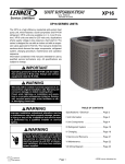
Flow rate ranges are based on 0.6 Sp. Gr. gas.
To determine capacity for other gases, use:
Q(g) = Q(.6)
0.6
G
Figure 1.3—Standard gas flow range
8
where
Q(.6)= Flow rate on graph at operating pressure
G = Sp. Gr. of other gas
Q(g) = Flow rate for other gas
September 2009
(SCFM)
MCFD
CU. M/DAY
(69444.4) 100000
2832000
(34722.2) 50000
1416000
(13888.9) 20000
566400
(6944.4)
10000
283200
(3472.2)
5000
141600
(1388.9)
2000
56640
(694.4)
1000
28320
(347.2)
500
14160
(138.9)
200
5664
(69.4)
100
2832
(34.7)
50
1416
(13.9)
20
566.4
(6.9)
10
283.2
(3.5)
5
141.6
(1.4)
2
56.6
(0.7)
1
1
(6.9)
28.3
2
(13.8)
5
(34.5)
10
(69)
20
(138)
50
(345)
100
(690)
200
(1380)
500
(3450)
1000
(6900)
2000
(13800)
FLOWING PRESSURE, PSIG (kPa)
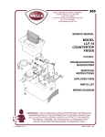
Flow rate ranges are based on 0.6 Sp. Gr. gas.
To determine capacity for other gases, use:
Q(g) = Q(.6)
0.6
G
Figure 1.4—Low gas flow range
September 2009
where
Q(.6)= Flow rate on graph at operating pressure
G = Sp. Gr. of other gas
Q(g) = Flow rate for other gas
9
10
September 2009
Section 2
Setup and Calibration
Installation
The NuFlo Gas Flowmeter must be installed properly to prevent gas from swirling or experiencing other erratic flow characteristics. Figure 2.1 shows the proper installation of the meter.
*10 nominal pipe diameters is the minimum recommended upstream pipe length.
If a flow straightener is not used, longer upstream pipe lengths may be required
to minimize measurement uncertainty due to swirl or asymmetrical flow.
Figure 2.1—Typical installation of an in-line gas turbine meter (minimum lengths). Upstream and downstream
sections are available in Schedule 40 and Schedule 80 pipe.
Calibration of Electronic Readout Equipment
Before a flowmeter leaves the factory, it is calibrated at multiple points within the flow range of the cartridge;
the factor is given in pulses per actual cubic foot (acf). This factor, which is recorded on a calibration tag that
is attached to the meter, is then used to calibrate electronic readout equipment in the field.
Fluid measured by the gas turbine meter is compressible, and is also affected by temperature changes. The
volumetric change caused by temperature and/or pressure for any ideal gas follows the equation below:
P1V1 P2 V 2
=
T1
T2
September 2009
11
Absolute Pressure and Temperature
The equation above shows that the volume of gas is determined by pressure and temperature. In this equation,
the pressure, P, is absolute pressure (the flowing or observed gauge pressure plus the atmospheric pressure).
The commonly used unit of measure for absolute pressure is pounds per square inch absolute (psia). For this
purpose, atmospheric pressure is considered to be 14.73 psi. Therefore,
Absolute pressure (psia) = Observed gauge pressure (psig) + 14.73 psi
The absolute temperature in the equation above is expressed in degrees Rankine, which is calculated as follows:
Degrees Rankine = Flowing gas temperature (°F) + 459.67
Calculating Gas Volume in Actual Cubic Feet
As a point of reference for discussing volumetric units of gas, one cubic foot (1ft3) of gas at a pressure of 1
atmosphere (assume 14.73 psia) at a temperature of 60°F (519.69°R) is considered one standard cubic foot
(scf). A cubic foot of gas at any other pressure and temperature is referred to as an actual cubic foot (acf) and
has no significance unless the conditions of pressure and temperature are known. For example, given 1 acf
of gas at 200 psig at 100°F, the volume of gas at standard conditions may be calculated with the following
formula:
standard pressure × volume observed pressure × 1 ft 3
=
standard temperature
observed temperature
3
14.73 × volume ( 200 + 14.73 ) × 1 ft
=
519.67
(100 + 459.67 )
Volume =
214.73 × 519.67
559.67 × 14.73
Volume = 13.536 ft 3
Therefore, 1 ft3 of gas at 200 psi and 100°F would occupy a volume of 13.536 ft3 if the pressure and temperature were reduced to standard conditions of 0 psi (14.73 psia) and 60°F. Numerous laboratory tests
have shown that the NuFlo Gas Flowmeter produces the same number of pulses per actual cubic foot of gas
regardless of the pressure and temperature of the gas when operated within its rated range. As a result, the
calibration factor can be specified in pulses per actual cubic foot. If the readout equipment for a gas meter
and the totalizer register in actual cubic feet, the flow totalizer divisor is set to the nearest whole number to
the calibration factor. The counter will then register actual cubic feet, regardless of the flowing pressure and
temperature.
Example:
Assume a 2-in. gas flowmeter with a calibration factor of 124.96 pulses per actual cubic foot, a flowline pressure of 70 psig, and a temperature of 80°F.
If the readout equipment divisor is set for 125, totalizer measurements will be in actual
cubic feet; if the readout equipment divisor is set for 1,250, totalizer measurements
will be in tens of actual cubic feet.
12
September 2009
Calculating Gas Volume in Standard Cubic Feet
Generally, gas is measured in standard cubic feet rather than actual cubic feet. Remember, at standard conditions (0 psi and 60°F), standard cubic feet and actual cubic feet are equivalent.
To convert actual cubic feet to standard cubic feet, use the following formula:
Standard Cubic Feet =
Actual Cubic Feet × Pf × Ts
Ps × Tf
where
Pf = flow pressure (psia)
Ps = standard pressure (14.73 psia)
Tf = flowing temperature (°R)
Ts = standard temperature (519.67°R)
Example
How many standard cubic feet are in each actual cubic foot at a flowing pressure of 70 psig
and a flowing temperature of 80°F?
1.0 × ( 70 + 14.73 ) × 519.67
= 5.539
Standard Cubic Feet =
14.73 × ( 80 + 459.67 )
The example above shows that there are 5.539 scf in every actual cubic foot at the flowing conditions of 70
psi at 80°F. The number of standard cubic feet may be obtained by setting the flow totalizer for the calibration
factor of the gas meter as previously described, and multiplying the registration by 5.539.
Example
A 2-in. gas turbine flowmeter with a calibration factor of 124.36 pulses per actual cubic foot
is installed in a flowline operating at 70 psig at 80°F. The flow totalizer divisor is set at 1,244
for registration in tens of actual cubic feet. Assume that during a 24-hour period, the totalizer
registers 2,327 counts. How many standard cubic feet were metered during this period?
Standard cubic feet = 2327 × 10 × 5.539 = 128,893
Determining the Divisor for Readout in Standard Cubic Feet
If the flowing conditions are kept constant, the multiplier for converting actual cubic feet to standard cubic feet will also remain constant. To simplify operations, consider this when computing the divisor for the
readout equipment and provide a direct readout in standard cubic feet. The following formula can be used to
determine the divisor for any given set of operating conditions:
Divisor =
FCF × Ps × Tf
Pf × Ts
September 2009
13
where
FCF= flowmeter calibration factor (pulses/acf)
Ps = standard pressure (14.73 psia)
Pf = flowing pressure (psia)
Tf = flowing temperature (°R)
Ts = standard temperature (519.67°R)
Example
A 2-in. gas turbine meter has a calibration factor of 124.36 pulses per actual cubic foot, and
is installed in a flowline operating at 70 psi at 80°F. Calculate the divisor for a flow totalizer to
register in standard cubic feet.
Divisor =
124.36 × 14.73 × ( 80 + 459.67 )
( 70+14.73 ) × 519.67
= 22.452
A divisor of 224 should be used for readings in tens of standard cubic feet, a divisor of 2,245
should be used for readings in hundreds of standard cubic feet.
Effects of Supercompressibility
The procedures described in this manual are applicable only when the flowing pressure and temperature
remain constant at the values used in the computation. If an application has a line pressure greater than 200
psig, the operator should consider the effects of supercompressibility and adjust the divisor accordingly.
The equation for calculating a divisor that allows for supercompressibility is
Divisor =
FCF × Ps × Tf
Pf × Ts × (Fpv )2
where Fpv = supercompressibility factor
Calibrating Equipment for Readout in Standard Cubic Feet Per Unit of Time
The readout equipment’s flow rate indicator and/or analog rate output may also be calibrated for the flowing
conditions to provide registration in standard cubic feet per unit of time.
The rate indicator will produce the full-scale output selected when the gas turbine meter generates the frequency corresponding to that output. The following formula may be used to calculate the full-scale frequency
for any particular readout device:
FSF =
14
FSFR × FCF × Ps × Tf
TBCF × Pf × Ts
September 2009
where
FSF = full-scale frequency (Hz)
FSFR = full-scale flow rate (scf/unit time)
FCF = flowmeter calibration factor (pulses/acf)
Ps = standard pressure (14.73 psia)
Tf = flowing temperature (°R)
TBCF = time-based conversion factor (seconds/unit time)
Pf = flowing pressure (psia)
Ts = standard temperature (519.67°R)
Example
Calculate the full-scale frequency for the readout in the previous example if the full-scale flow
rate is 1,500 Mscf/D.
FSF =
1,500,000 × 124.36 × 14.73 × ( 80 + 459.67 )
= 389.78 Hz
24 hr 60 min 60 sec
×
×
× ( 70+14.73 ) × 519.67
day
hr
min
The readout device should indicate 1500 Mscf/D flow with a 389.78 Hz signal fed into the
flowmeter signal input.
Effects of Fluctuating Temperatures
In some applications, temperature does not remain constant and the operator must determine to what degree
changing temperatures affect readout accuracy. In many cases, changes in temperature will not produce serious measurement errors and can often be ignored. However, where temperature changes are more extreme,
the user may recalibrate the readout equipment seasonally to offset the impact of wide ranges of temperature
changes from summer to winter.
Figure 2.2 illustrates how fluctuations in flowing temperature cause errors in standard cubic feet.
To determine the effect of temperature changes on readout accuracy, see the example below.
A 2-in. gas turbine flowmeter is installed in a flowline operating at 70 psig at 80°F. At standard conditions,
1 ft3 of gas will occupy 5.539 ft3. Determine the effects of a 10% change in temperature.
10% of 80° = 8°; therefore, the maximum temperature is 88°F and the minimum temperature is 72°F.
At 88°F,
Standard Cubic Feet =
1.0 × ( 70 + 14.73 ) × 519.67
14.73 × ( 88 + 459.67 )
= 5.458
At 72°F,
Standard Cubic Feet =
September 2009
1.0 × ( 70 + 14.73 ) × 519.67
14.73 × ( 72 + 459.67 )
= 5.622
15
At 80°F, each actual cubic foot equaled 5.539 scf. The percentage of change caused by increasing the flow
temperature to 88°F is shown below:
% Change =
5.539 − 5.458
× 100 = -1.46 %
5.539
The percentage of change caused by decreasing the flow temperature to 72°F is shown below:
% Change =
5.622 − 5.539
× 100 = 1.50 %
5.539
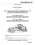
Effects of Fluctuating Pressures
In some applications, pressure does not remain constant and the operator must determine to what degree
changing pressures affect readout accuracy. Small changes in pressure can produce large errors in standard
cubic feet, especially at low flowing temperatures. Figure 2.3 illustrates the effect of fluctuations in flowing
pressure on standard cubic feet. Note how the effect of changing pressure is much greater than the effect of
changing temperature. The overall effect of changing temperature and pressure is the algebraic sum of the
individual effects.
To determine the effect of pressure changes on readout accuracy, see the example below.
Example
A 2-in. gas turbine flowmeter is installed in a flowline operating at 70 psig at 80°F. At standard conditions, 1 ft3 of gas will occupy 5.539 ft3. Determine the effects of a 10% change
in temperature.
10% of 70 psig is 7 psig; therefore, the maximum pressure is 77 psig and the minimum pressure is 63 psig.
At 63 psig,
Standard Cubic Feet =
At 77 psig,
Standard Cubic Feet =
1.0 × ( 63 + 14.73 ) × 519.67
( 80 + 459.67 ) × 14.73
1.0 × ( 77 + 14.73 ) × 519.67
( 80 + 459.67 ) × 14.73
= 5.081
= 6.000
At 70 psig, each actual cubic foot equals 5.539 scf.
The percentage of change caused by reducing the flowing pressure to 63 psig is shown
below:
% Change =
5.081 − 5.539
× 100 = -8.27 %
5.539
The percentage of change caused by increasing the flowing temperature to 77 psig is shown
below:
% Change =
16
6.000 − 5.539
× 100 = 8.32 %
5.539
September 2009
When faced with varying flowing pressures, consider the following alternatives:
1. Sense the pressure on the flowline and correct the output from the flowmeter.
2. Control the pressure to hold it constant within the limits of error that can be tolerated.
Alternative No. 1 requires a pressure-compensated readout, or the use of a computer that can receive a sign
representing pressure and compensate for the flowmeter signal.
Alternative No. 2 is normally the least expensive since it requires only the installation of a pressure regulator
in the flowline downstream of the flowmeter.
September 2009
17
18
September 2009
0
0
2.0
4.0
6.0
8.0
10.0
12.0
20
40
60
10°F Change
20°F Change
30°F Change
40°F Change
50°F Change
100
120
140
160
180
Flowing Temperature (°Rankine)
Variation in Temperature (°Fahrenheit)
Flowing Temperature, °F
80
% Error =
200
Figure 2.2—Effect of change in temperature on gas volume measurements. Positive and negative changes in temperature produce virtually the
same error.
Percentage of Error in Gas Volume Readout
September 2009
19
0
5
10
15
20
25
30
0
100
200
10-psi Change
20-psi Change
30-psi Change
40-psi Change
50-psi Change
300
400
600
700
800
Absolute Flowing Pressure (psia)
Variation in Gage Pressure (psig)
Flowing Pressure, psi
500
% Error =
900
1000
Figure 2.3—Effect of change in pressure on gas volume measurements. Positive and negative changes in pressure produce virtually the same
error.
Percentage of Error in Gas Volume Readout
20
September 2009
Section 3
Maintenance
Because all internal components of the 2-in. gas flowmeter are contained within a cartridge, maintenance of
this instrument is minimal. Should a flowmeter fail, the internal cartridge can be easily and quickly replaced
in the field. See the following procedure for removing and replacing cartridges. See Tables 3.1 through 3.3 for
ordering information.
Removing and Replacing Cartridges
IMPORTANT—Never disassemble or adjust a cartridge before installing it. Each cartridge is precalibrated as
a unit at the factory.
To replace a gas flowmeter cartridge, perform the following steps:
1. Remove the meter from the flowline.
2. Remove the magnetic pickup.
3. Remove the retainer rings from each end of the housing.
4. Press the cartridge out from either end of the housing.
IMPORTANT—Do not press on the struts; they may bend.
5. Locate the point next to the hole in the top of the new cartridge. This point indicates flow direction.
6. Position the new cartridge so that the flow direction indicated on the cartridge matches the flow direction indicated by the arrow on the flowmeter housing.
7. Snap the cartridge into place, taking care to apply pressure only to the outer diameter of the cartridge.
8. Rotate the cartridge until the hole in the top lines up with the threaded hole in the housing used to attach the magnetic pickup.
9. Install retainer rings into each end of the housing.
10. Replace the magnetic pickup by screwing it in hand-tight and securing the jam nut. DO NOT OVERTIGHTEN.
11. Replace the flowmeter in the flowline, ensuring that the flow direction arrow points in the proper
direction.
12. For positive factor identification, wrap the strap of the plastic tag bearing the factor around the conduit adapter, thread the end of the strap through the hole in the tag and pull tight. Cut off excess strap
length.
September 2009
21
Flowmeter Assemblies
The 2-in. gas flowmeter assembly is available in three different styles to accommodate standard, high, and
low flow rates. See Table 3.1 below for the part numbers for these assemblies.
Table 3.1—Gas Flowmeter Assemblies
Part Number
Description
9A-100003397
Gas meter assembly, low flow range
9A-100003398
Gas meter assembly, standard flow range
9A-100003399
Gas meter assembly, high flow range
Spare Parts
The following spare parts are recommended for use with the NuFlo 2-in. Gas Flowmeter.
Table 3.2—Spare Parts
Part Number
Qty.
Description
9A-100003517
1
Cartridge, rotor assembly (standard range)
9A-100005113
1
Cartridge, rotor assembly (low range)
9A-100005134
1
Cartridge, roter assembly (high range)
9A-100003518
1
Pickup, magnetic
9A-100062541
2
Centering ring
9A-100005137
1
Pickup adapter extensions (required with 300,
600 and 900 ANSI flanges)
9A-100020977
2
Retaining ring
Accessories
The following accessories are available for use with the NuFlo 2-in. Gas Flowmeter. The installation hardware kit includes bolts, nuts, and gaskets for installing the meter in a pipeline.
Table 3.3—Accessories
22
Part Number
Description
9A-100005100
Installation hardware kit, 150 lb flange
9A-100079589
Installation hardware kit, 300 lb flange
9A-100005101
Installation hardware kit, 600 lb flange
9A-100079906
Installation hardware kit, 900 lb flange
9A-50336500100
Flow straightener, line type, 2-in., Sch. 40, 1100L carbon steel
9A-50336500101
Flow straightener, line type, 2-in., Sch. 80, 1100L carbon steel
9A-50336500104
Flow straightener, line type, 2-in., Sch. 40, 1106L 316SS
9A-50336500105
Flow straightener, line type, 2-in., Sch. 80, 1106L 316SS
September 2009
WARRANTY - LIMITATION OF LIABILITY: Seller warrants only title to the products, software, supplies and materials and that, except as to software, the same are free from defects
in workmanship and materials for a period of one (1) year from the date of delivery. Seller
does not warranty that software is free from error or that software will run in an uninterrupted
fashion. Seller provides all software “as is”. THERE ARE NO WARRANTIES, EXPRESS
OR IMPLIED, OF MERCHANTABILITY, FITNESS OR OTHERWISE WHICH EXTEND
BEYOND THOSE STATED IN THE IMMEDIATELY PRECEDING SENTENCE. Seller’s liability and Buyer’s exclusive remedy in any case of action (whether in contract, tort, breach
of warranty or otherwise) arising out of the sale or use of any products, software, supplies,
or materials is expressly limited to the replacement of such products, software, supplies,
or materials on their return to Seller or, at Seller’s option, to the allowance to the customer
of credit for the cost of such items. In no event shall Seller be liable for special, incidental,
indirect, punitive or consequential damages. Seller does not warrant in any way products,
software, supplies and materials not manufactured by Seller, and such will be sold only with
the warranties that are given by the manufacturer thereof. Seller will pass only through to
its purchaser of such items the warranty granted to it by the manufacturer.