1
USER MANUAL
ETU02A-MUX
Standalone Series
2/4-Data Ports Multiplexer
Fractional E1 Access Unit
With Optional Sub-Link E1 Port
The information contained in this document is subject to change without prior notice.
TRADEMARKS
Microsoft is a registered trademark of Microsoft Corp.
HyperTerminal™ is a registered trademark of Hilgraeve Inc.
WARNING:
This equipment has been tested and found to comply with the limits for a Class A digital device, pursuant to
Part 15 of the FCC Rules. These limits are designed to provide reasonable protection against harmful
interference when the equipment is operated in a commercial environment. This equipment generates, uses,
and can radiate radio frequency energy and if not installed and used in accordance with the instruction manual
may cause harmful interference in which case the user will be required to correct the interference at his own
expense. NOTICE: (1) The changes or modifications not expressively approved by the party responsible for
compliance could void the user's authority to operate the equipment. (2) Shielded interface cables and AC
power cord, if any, must be used in order to comply with the emission limits.
CISPR PUB.22 Class A COMPLIANCE:
This device complies with EMC directive of the European Community and meets or exceeds the following
technical standard. EN 55022 - Limits and Methods of Measurement of Radio Interference Characteristics of
Information Technology Equipment. This device complies with CISPR Class A.
WARNING:
This is a Class A product. In a domestic environment this product may cause radio interference in which case
the user may be required to take adequate measures.
CE NOTICE
Marking by the symbol CE indicates compliance of this equipment to the EMC directive of the European
Community. Such marking is indicative that this equipment meets or exceeds the following technical standards:
EN 55022:1994/A1:1995/A2:1997 Class A and EN61000-3-2:1995, EN61000-3-3:1995 and EN50082-1:1997
CTC Union Technologies Co., Ltd.
Vienna Technology Center
8F, No. 60, ZhouZi St.,
NeiHu, Taipei, 114
Taiwan
ETU02A-MUX 4 Port MUX, Fractional E1, Installation and Operation Manual
Version 1.1 Feb. 2005 Printing
This manual supports the following models:
ETU02A-MUX.2-XX-AC, 2 Port MUX, universal AC
ETU02A-MUX.4-XX-AC, 4 Port MUX, universal AC
ETU02A-MUX.2-XX-DC, 2 Port MUX, DC model
ETU02A-MUX.4-XX-DC, 4 Port MUX, DC model
TABLE OF CONTENTS
CHAPTER 1. INTRODUCTION ………………….……………………… 1
1.1 INTRODUCTION ………………………………………………………………
1.2 FUNCTION DESCRIPTION ……………………………………………………
1.3 TYPICAL SYSTEM APPLICATIONS …………..……………………………..
1.4 E1 SIGNAL STRUCTURE ……………………………………………………..
1.5 ETU02A-MUX CAPABILITIES …………………………………………………
1.6 TECHNICAL SPECIFICATIONS ………………………………………………
1
1
3
4
5
6
CHAPTER 2. INSTALLATION ………………..………………………… 11
2.1 GENERAL ……………………………………………………………………….
2.2 SITE PREPARATION ……………………………….………………………….
2.3 MECHANICAL ASSEMBLY ……………………..…………………………….
2.4 ELECTRICAL INSTALLATION ………………………………………………
2.5 DIP SWITCH SETTING AND INTERFACE TERMINATION STRAPPING .
2.6 INTERFACE SOFTWARE CONFIGURATION ………………………………
11
11
11
11
12
14
CHAPTER 3. CONTROL PORT OPERATION ……………………....… 15
3.1 GENERAL ………………………………………………………………………. 15
3.2 TERMINAL CONNECTION …………………………………………………… 15
3.3 MENU SYSTEM DETAIL ……………………………………………………… 16
CHAPTER 4. TEST and DIAGNOSTICS ………………………..……… 27
4.1 GENERAL ………………………………………………………………………. 27
4.2 STATUS INDICATORS …………………..……………………………………. 27
4.3 USER ACTIVATED LOOPBACK ……………………………………………… 28
i
TABLE OF CONTENTS
APPENDIX A. DIP SWITCH SETTING ………………………………….. 35
A.1 DSW1 SETTING …………………………………………………………………..
A.2 DSW2 SUB E1 LINE IMPEDANCE SETTING …………………………………
A.3 SW1 MAIN E1 LINE IMPEDANCE SETTING …………………………………
A.4 JUMPER CHASS1 FRAME GROUND …………………………………………
35
35
35
35
APPENDIX B. CONNECTORS …………………….……………………… 37
B.1 E1 LINE CONNECTORS …………………………………………………………
B.2 V.35 USER DATA CHANNEL CONNECTOR ………………………………….
B.3 RS-530 USER DATA CHANNEL CONNECTOR ……………………………….
B.4 RS-232 USER DATA CHANNEL CONNECTOR ……………………………….
B.5 RS-530 to RS-449 ADAPTER CABLE ……………………………………………
B.6 RS-530 to X.21 ADAPTER CABLE …………….………………………………...
B.7 RS-232/ALARM PORT CONNECTOR ………………………………………….
37
38
39
40
41
42
43
NOTES ………………………………………………………………………... 45
ii
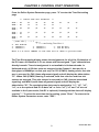
CHAPTER 1. INTRODUCTION
1-1. INTRODUCTION
The ETU02A-MUX provides an economical data multiplexing solution for E1 and
Fractional E1 network services. Depending upon the model, two or four DTE devices
may be linked to an ETU02A-MUX at data rates of 56Kbps to 1984Kbps (framed mode).
The ETU02A-MUX also provides one optional E1 sub-link (drop and insert). The E1
sub-link will perform Drop & Insert on connections from a PABX or other E1 equipment
to E1 network services using user-defined timeslot.
The ETU02A-MUX supports local control and diagnostics via a console (craft) port
connection (RS-232 Async). This feature enables users to easily configure the unit and
execute the in-service diagnostics either locally or remotely (via modem connection).
1-2. FUNCTIONAL DESCRIPTION
The ETU02A-MUX data channels support user-selectable transmission rates, which
are integer multiples of 56 or 64kbps, up to a maximum 1.984Mbps (CCS framing), for a
line attenuation of up to -43 dB on twisted pair or coax cable. An integral LTU is
included, providing an approximate operating range of up to 2km (using 22AWG).
The ETU02A-MUX packs the data channels into the E1 link in user-selected time
slots, while the unused time slots may insert a user assigned IDLE code.
The ETU02A-MUX supports selection of three major data channel interfaces: RS232(SYNC), V.35, and RS-530. Additionally, RS-449 and X.21 are supported via adapter
cables attached to an RS-530 configured interface.
The ETU02A-MUX fully meets E1 specifications including ITU-T G.703, G.704,
G.706, G.732, and G.823.
The ETU02A-MUX features diagnostic capabilities for performing local loop back
and remote digital loop back. The operator at either end of the line may test both the
ETU02A-MUX and the E1 link in the digital loop back mode. The loop back is
controlled by menu selection on an ASCII terminal attached to the control (craft) port.
1
ETU02A MAY 2000
CHAPTER 1. INTRODUCTION
During loop back testing a number of internal pseudo random test patterns may be
generated, according to ITU-T, for direct end-to-end integrity testing. The Error indicator
flashes for each bit error detected.
Multiple clock source selection provides maximum flexibility in connecting both the
E1 and user interfaces. The E1 link may be clocked from the E1 recovered receive clock
(main E1 link or sub E1 link), from any one of the user data ports, or from the internal
oscillator.
The ETU02A-MUX has following master timing modes:
• MAIN LINK: Timing is recovered from the main E1 link.
• SUB LINK: Timing is recovered from the E1 sub-link
• INT OSC: Timing is provided by the internal oscillator of the ETU02A-MUX.
• CH1 LINK: Timing is recovered from the Data Channel 1.
• CH2 LINK: Timing is recovered from the Data Channel 2.
• CH3 LINK: Timing is recovered from the Data Channel 3.
• CH4 LINK: Timing is recovered from the Data Channel 4.
The ETU02A-MUX data channel interface supports three clocking modes:
• Mode 1 (DCE ): DCE interface. The ETU02A-MUX provides the transmit and
receive clocks to the user’s equipment connected to the data channel.
• Mode 2 (DTE 1): DTE interface. The ETU02A-MUX data channel accepts the user
transmit clock and provides a receive clock (Transparent timing) to the user’s
equipment connected to the data channel.
• Mode 4 (DTE 3): DTE interface. The ETU02A-MUX data channel accepts the user
transmit and receive clock (All from ETC pin) provided by the equipment connected
to the data channel.
The ETU02A-MUX operates from 90VAC ~ 250VAC. The unit is built in a single unit
high, EIA compliant 19” rack mountable case, that may also be placed on desktops or
shelves. DC model units are also available for 24 volts or -48 volts.
2
ETU02A MAY 2000
CHAPTER 1. INTRODUCTION
1-3. TYPICAL SYSTEM APPLICATIONS
General
In a typical application (Figure 1-1), the ETU02A-MUX could be used to connect
the synchronous data channels of two host computers and the local and remote LANs
over an E1 line. The following example is using the ETU02A-MUX.2 two data port
multiplexer.
Figure 1-1: Example 1; Two Channel Typical Application
Figure 1-2: Example 2; Four Channel plus E1 Sub-Link Application
Figure 1-3: Example 3; Cascade ETU02A from E1 Sub-Link Application
The fractional E1 data service is based on the assumption that the combined user
data rate of all channel modules plus Sub-Link is equal to or is a fraction of the full
available E1 bandwidth, in multiples of 56K or 64K. Up to four data channels may be
connected (ETU02A-MUX.4, two for the ETU02A-MUX.2) plus an optional E1 sub-link.
3
ETU02A MAY 2000
CHAPTER 1. INTRODUCTION
1-4. E1 signal structure
The E1 line operates at a nominal rate of 2.048Mbps. The data transferred over the
E1 line is organized into frames, with each E1 frame containing 256 bits. The 256 bits are
organized as 32 time slots of eight bits each, that carry the data payload.
E1 transmissions utilize two main types of framing: Frame Alignment Signal (FAS)
and Multi-Frame Alignment Signal (MFAS). Framing is necessary in order for
equipment receiving the E1 signal to be able to identify and extract the individual
channels. PCM-30 (CAS) transmission systems use MFAS framing along with FAS
framing. PCM-31 (CCS) transmission systems use only FAS framing.
Frame Alignment Signal (FAS)
As previously mentioned, the 2.048 Mbps E1 frame consists of 32 individual time
slots (numbered 0-31). Each time slot consists of an individual 64 Kbps channel of data.
In the FAS format, time slot 0 of every other frame is reserved for the frame alignment
signal pattern. Alternate frames contain the FAS Distant Alarm indication bit, SA bits and
others bits reserved for national and international use. We refer to this frame mode as
CCS or more commonly as PCM31, 31 timeslots are available for carrying data.
Multi-Frame Alignment Signal (MFAS)
MFAS framing uses Channel Associated Signaling (CAS) to transmit the A/B/C/D
bits signaling information for each of 30 channels. This method uses the 32 time slot
frame format with time slot 0 dedicated for the Frame Alignment Signal (FAS) and time
slot 16 dedicated for the Multi-Frame Alignment Signal (MFAS) and the Channel
Associated Signaling (CAS). We refer to this framing mode as CAS or more commonly
PCM30, 30 timeslots are available for carrying data.
E1 line signal
The basic E1 line signal is coded using the Alternate Mark Inversion (AMI) or
HDB3 rule.
In the AMI format, “ones” are alternately transmitted as positive and negative pulse,
whereas “zeros” are transmitted as a zero voltage level. AMI is not used in most 2.048
Mbps transmissions because synchronization loss occurs during long strings of data zeros.
In the HDB3 format, a string of four consecutive zeros is replaced with a substitute
string of pulses containing an intentional bipolar violation. The HDB3 code substitutions
provide high pulse density so that the receiving equipment is able to maintain
synchronization with the received signal.
4
ETU02A MAY 2000
CHAPTER 1. INTRODUCTION
1-5. ETU02A-MUX Capabilities
E1 link line coding
The ETU02A-MUX supports two E1 line codes:
AMI coding.
HDB3 coding.
E1 framing formats
The ETU02A-MUX supports five formats:
Unframed format. (Data Port Ch.1 active only)
FAS (CCS, PCM-31) format.
FAS (CCS, PCM-31) plus CRC4 format.
MFAS (CAS, PCM-30) format.
MFAS (CAS, PCM-30) plus CRC4 format.
User data channel rates
The ETU02A-MUX supports user data channel rates which are a multiple of 56 or
64kbps. For maximum flexibility, the ETU02A-MUX supports data rates up to
1.984Mbps. (2.048Mbps unframed, data port channel 1 active only) The ETU02A-MUX
supports flexible time slot assignment, allowing the user to freely specify the selection of
time slots for each data channel sequentially or randomly.
User data channel interface
The ETU02A-MUX has three types of hardware configurable and software
selectable user data channel interfaces that utilize common fixed DB25F connectors:
RS-232(SYNC), V.35, and RS-530. The ETU02A-MUX also supports RS-449 and X.21
data channels via adapter cables attached to an RS-530 configured interface. The
ETU02A-MUX.2 supports two data channel port interfaces, while the ETU02A-MUX.4
supports up to four data channel port interfaces.
5
ETU02A MAY 2000
CHAPTER 1. INTRODUCTION
1-6. TECHNICAL SPECIFICATIONS
Main link E1 and sub link E1
Framing
Bit Rate
Line Code
Line Impedance
Relative Receive Level
“Pulse” Amplitude
“Zero” Amplitude
Transmit Frequency Tracking
Internal Timing
Loopback Timing
External Timing
Jitter Performance
Complies With
Interface Connectors
-Unframed/Framed (Sub E1 Framed ONLY!)
-CCS (PCM31)/CAS (PCM30)
-CRC4 ON/OFF
2.048 Mbps
-AMI
-HDB3
-Unbalanced 75 ohms
-Balanced 120 ohms
0 to -43dB
-Nominal 2.37V±10% for 75 ohms
-Nominal 3.00V±10% for 120 ohms
±0.1V
±30 ppm
±50 ppm
±100 ppm
According to ITU-T G.823
ITU-T G.703, G.704, G.706 and G.732
-15-pin, D-type Female (balanced)
-BNC (unbalanced)
6
ETU02A MAY 2000
CHAPTER 1. INTRODUCTION
User Data Channels
Interfaces Type
- V.35
- RS-232 (SYNC)
- RS-530 (RS-449, X.21)
Interface Cable Connectors
V.35 Interface
RS-232 Interface
RS-530
X.21 Interface
RS-449 Interface
Line Code
Data Rate
Clock Modes
Clock Mode 1 (DCE)
Clock Mode 2 (DTE1)
Clock Mode 4 (DTE3)
Control Signals
Time slot allocation
25 pin to 34 pin, Female cable
25 pin, D-type Female
25 pin, D-type Female
25 pin to 15 pin, D-type Female cable
25 pin to 37 pin, D-type Female cable
NRZ
N×56kbps or N×64kbps
where N equal 1 to 31 in CCS
or N equal 1 to 30 in CAS
Receive and transmit clock (recovered) to the
synchronous DTE
Receive clock to the synchronous, and transmit
clock from the synchronous device. (transparent)
Receive and transmit clock from the synchronous
DCE (all from the ETC pin).
-CTS constantly ON or follow RTS
-DSR constantly ON, except during test loops
-DCD constantly ON, except during signal loss
User defined
LED indicators
PWR
Signal Loss
Sync Loss
Alarm
Green
Red
Red
Red
Signal Loss
Sync Loss
Alarm
Red
Red
Red
CH1~CH4
Test Error
Test
Yellow
Red
Red
Power
E1 link signal loss
E1 link sync loss
E1 link alarm, includes: BPV error / CRC4 error /
Frame slip / Alarm Indication Signal (AIS) / Remote
alarm (RAI)
Sub-E1 link signal loss
Sub-E1 link sync loss
Sub-E1 link alarm, includes: BPV error / CRC4 error /
Frame slip / Alarm Indication Signal (AIS) / Remote
alarm (RAI)
RD/TD activity indicators for Data Channels
Bit errors
Unit in Loop back or BERT test active
7
ETU02A MAY 2000
CHAPTER 1. INTRODUCTION
Diagnostic tests
Test loops
-Main link local analog loop back
-Main link local digital loop back
-Main link remote loop back
-Sub link local analog loop back
-Sub link local digital loop back
-Sub link remote loop back
-User’s channel (1-4) local digital loop back
-User's channel (1-4) local analog loop back
-User’s channel (1-4) remote loop back
BERT test pattern
-511
-2047
-2^15-1
-2^20-1
-QRSS
-2^23-1
-All ones
-All zeros
-ALT
-Double ALT (11001100….)
-3 in 24
-1 in 16
-1 in 8
-1 in 4
RS-232/Alarm (craft) port
Port interface
Port connector
Data rate
Data format
Alarm relay
V.24 / RS-232 asynchronous
9 pin D-type female
2400, 4800, 9600, or 19200 baud
-One start bit
-8 data bits
-No parity
-One stop bit
-Floating pair of NO and NC contacts
-Contact ratings: 1A at 30 VDC resistive
or 0.5A at 125 VAC resistive
(NC contacts open on loss of power or loss of signal on main E1 or Sub E1.)
8
ETU02A MAY 2000
CHAPTER 1. INTRODUCTION
Physical
Height:
Width:
Depth:
Weight:
45 mm
430 mm
235 mm
2.75 kg
Power supply
Voltage
Frequency
Power consumption
Fuse
90 ~ 250 VAC, +24VDC, or -48VDC
47 to 63 Hz for AC power
15 Watts
0.5A slow blow for VAC
Environment
Temperature
Humidity
0-50C / 32-122F
0 to 90% non-condensing
9
ETU02A MAY 2000
CHAPTER 1. INTRODUCTION
This page left blank intentionally.
10
ETU02A MAY 2000
CHAPTER 2. INSTALLATION
2-1. GENERAL
This chapter provides detailed instructions for mechanical installation of the
ETU02A-MUX. Following the completion of installation, please refer to Chapter 3 for
console port operating information.
2-2. SITE PREPARATION
Install the ETU02A-MUX within reach of an easily accessible grounded AC outlet.
The outlet should be capable of furnishing 90 to 250 VAC. Allow at least 10cm (4 inch)
clearance at the rear of the ETU02A-MUX for signal lines and interface cables.
2-3. MECHANICAL ASSEMBLY
The ETU02A-MUX is designed for tabletop, shelf or rack mount installation, and
except for rack mount installation, is delivered completely assembled. Rack mounted
applications require installation of additional rack mounting “ears”. No provisions are
made for bolting the ETU02A-MUX to the tabletop.
2-4. ELECTRICAL INSTALLATION
2-4-1. Power connection
AC power is supplied to the ETU02A-MUX through a standard IEC 3-prong plug.
(Refer to Figure 2-1) The ETU02A-MUX should always be grounded through the
protective earth lead of the power cable.
The line fuse is in an integral-type fuse holder with the IEC power connector located
on the rear panel. Make sure that only fuses of the required rating are used for
replacement. Do not use repaired fuses or short-circuit the fuse holder. Always disconnect
the power cable before removing or replacing the fuse.
2-4-2. Rear panel connectors
The data port channel interfaces (DCE) are accessible from the rear panel of the
ETU02A-MUX (Refer to Figure 2-1) and consist of DB25pin Female connectors. Direct
connections are allowed for RS-232 (SYNC) and RS-530. Adapter cables are required for
V.35, RS-449, and X.21. The E1 line and E1 sub-link connectors incorporate one
DB15pin each or two pairs of BNC Coax connectors. (Appendix B provides detailed
information on the various interface connectors).
Figure 2-1 ETU02A-MUX rear panel
11
ETU02A MAY 2000
CHAPTER 2. INSTALLATION
E1 Line side
DB-15 Connector (Balanced 120 ohm)
The pin assignments for DB-15 connector are as follows:
Pin:
1
9
3
11
Function:
TTIP (Transmit data out)
TRING (Transmit data out)
RTIP (Receive data in)
RRING (Receive data in)
BNC coax connector (Unbalanced 75 ohm)
Two BNC coax connectors marked RX and TX (Same function as the E1 line DB15
connector).
Data channel Interfaces
All data port interfaces utilize a pin-out based upon a standard DSUB-25F connector.
Software control, hardware strapping and adapter cables provide the appropriate connects
for V.35, RS-449 and X.21. RS232 and RS-530 may connect directly to the ETU02AMUX. Please refer to the interface pin out and adapter cable specifications in the
appendix.
Cable and Termination
Use a shielded twisted pair cable between the ETU02A-MUX and the DTE device. The
receivers on the ETU02A-MUX are 100 Ohm terminated (For X.21 and RS-530). If
problems are encountered with the connection to the DTE interface, make sure that the
ETU02A-MUX and DTE interface are terminated correctly.
2-5. DIP Switch Setting and Interface Termination Strapping
2-5-1. Caution
To avoid accidental electric shot, disconnect the ETU02A-MUX power cord before
opening the cover. Access inside the equipment is only permitted to authorized and
qualified service personnel.
2-5-2. Procedure
a.
b.
c.
d.
e.
f.
g.
Turn power OFF. Disconnect the power cord from the AC outlet.
Loosen the captive thumb screws on the left and right sides of the rear panel.
Slide the outer housing forward to reveal the main PCB.
Adjust the DIP switches as required, according to table 2-1.
Add or remove the interface terminating resistors according to table 2-2.
Slide the PCB assembly back into the outer housing and tighten the thumb screws.
Perform any necessary interface configuration via the terminal control port.
12
ETU02A MAY 2000
CHAPTER 2. INSTALLATION
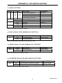
Table 2-1
Item Function
1
2
3
4
5
7
8
9
Craft port Speed
9600
2400
19200
4800
Reserved
Reserved
Reserved
Interface Setup
Main E1 Impedance
Sub E1 Impedance
Frame ground
Possible
Switch
Settings
On / Off
Designation
DSW1-1
On / Off
On / Off
On / Off
On / Off
All On=75Ω, All Off=120Ω
All On=75Ω, All Off=120Ω
DIS: Not connected to signal ground
Factory
DSW1-2
OFF
OFF
OFF
ON
ON
OFF
ON
ON
DSW1- 2
DSW1- 3
DSW1- 4
DSW1- 5
DSW2- 1~5
SW1- 1~5*
CHASS1
Setting
Off/Off
Off
Off
Off
Off
All Off
All Off
DIS
CON: Connected to signal ground
DSW1 and DSW2 are located on the main PC Board.
*Switch SW1 is located on the optional Sub E1 Interface card.
Table 2-2
Port
1
2
3
4
Interface
Type
V.35
RS232
RS-530
V.35
RS232
RS-530
V.35
RS232
RS-530
V.35
RS232
RS-530
Possible
Settings
Present / Absent
Present / Absent
Present / Absent
Present / Absent
Present / Absent
Present / Absent
Present / Absent
Present / Absent
Present / Absent
Present / Absent
Present / Absent
Present / Absent
Resistor
Designation
RP18, 19, 21
RP18, 19, 21
RP18, 19, 21
RP16, 17, 20
RP16, 17, 20
RP16, 17, 20
RP15, 14, 23
RP15, 14, 23
RP15, 14, 23
RP12, 13, 22
RP12, 13, 22
RP12, 13, 22
Setting
All Present
All Absent
RP21 Only
All Present
All Absent
RP20 Only
All Present
All Absent
RP23 Only
All Present
All Absent
RP22 Only
Factory
Setting
9
9
9
9
Note: For RS-449 and X.21, please use the RS-530 settings.
Resistor pack values:
RP18, RP16, RP15 and RP12 (5 pin) 300 ohm
RP19, RP17, RP14 and RP13 (9 pin) 560 ohm
RP21, RP20, RP23 and RP22 (8 pin) 180 ohm
IMPORTANT: When replacing resistor packs, take extreme care to align the pins in the
sockets and to orient the "DOT" on the pack with the "square" on the PCB silkscreening for
proper termination.
13
ETU02A MAY 2000
CHAPTER 2. INSTALLATION
2-6. Interface Software Configuration
Preparing the proper interface cables and strapping the appropriate termination resistor
packs according to Table 2-2 will complete the hardware setup of the interface ports. For
proper operation, however, the board firmware must be made aware of the changes. This
special procedure, using a terminal attached to the local control serial port, need only be
performed during initial installation and/or configuration of the ETU-02A. Please familiarize
yourself with the connection and operation procedures for the Control Port operation in
Chapter 3. Once you are comfortable with the terminal port operation, proceed to configure the
data channel interface ports as follows.
1. With the unit powered off and main PCB exposed, set DIP DSW1 switch 5, ON.
2. Replace PCB, connect terminal to control port and apply power.
3. From the main menu select item "2", Define System Parameter.
4. From the Define System Parameter menu, select item "5", Data Port.
5. From the Define Data Port Parameter menu, select a port for configuration, "1 thru 4".
6. Select item "6", Interface, from the menu. (This item not displayed if DSW1-5 not ON)
7. Select item "1" for RS-232, item "2" for V.35, or item "3" for RS-530/449 or X.21.
8. Press "ESC" and select another port for configuration. Follow the same procedure.
9. After completing the interface configuration for each port, press "ESC" until the top menu.
10. Select item "5" to exit terminal mode.
11. Power off the ETU-02A, open the case, set DSW1-5 OFF, and close the case.
Configuration of the channel ports interface is now complete.
14
ETU02A MAY 2000
CHAPTER 3. CONTROL PORT OPERATION
3-1. General
The ETU02A-MUX Control Port (labeled RS-232/Alarm on the rear panel) is an RS-232
asynchronous console terminal port designed to facilitate setup of all parameters through
the use of a standard text based terminal or any terminal emulation program running on a
Personal Computer.
3-2. Terminal Connection
A notebook computer has become an invaluable tool of the Systems Engineer.
Connection to the computer is straight forward. The only other hardware required is a
DB9-pin one-to-one, male to female cable. The ETU02A-MUX acts as a DCE to the PC’s
DTE communications port. A convenient application, provided with the Microsoft
Windows 9X operating systems, is “HyperTerminal ™”. Set the properties to match the
ETU02A-MUX control port factory defaults as follows: Baud=9600, Data bits=8,
Parity=None, Stop bits=1, and handshaking=none. Make the appropriate connections,
start the terminal application, apply power to the ETU02A-MUX, then press SPACE or
ENTER on the PC keyboard. If you are using “HyperTerminal ™” the display should
look like the following.
Figure 3-1. Example of terminal display
15
ETU02A MAY 2000
CHAPTER 3. CONTROL PORT OPERATION
3-3. Menu System Detail
The following section will detail actual displays with descriptions of parameter settings
via relevant key commands.
This is the first screen seen after connecting. Note that the first two items, "Display" and
"Define" deal with all the system settings. The "Display" item will give a quick overview of
all settings, while under "Define", all parameters may be both viewed and changed.
********************************************
****
****
****
ETU-02A TERMINAL MODE
****
****
SETUP MENU Ver. 1.01
****
********************************************
1.
2.
3.
4.
5.
Display System Status.
Define System Parameter.
Test Function Parameter.
Reset Data to Default.
EXIT
Enter 1-5 to select function.
Enter 1 to enter the Display System Status menu.
<<
Display System Status
Only shown if option installed
>>
Timing : < Internal OSC >
Frame :
CRC4 :
Idle Code :
RAI :
Line Code :
Impedance :
SLOT
TYPE
SLOT
TYPE
SLOT
TYPE
SLOT
TYPE
:
:
:
:
:
:
:
:
[ Main E1 ]
CCS
Disable
7E
Disable
HDB3
75 ohm
[ Sub E1 ]
CCS
Disable
7E
Disable
HDB3
75 ohm
[ Time Slot Mapping ]
00
01
02
03
Fr
c1
c1
c2
08
09
10
11
.
.
.
.
16
17
18
19
.
.
.
.
24
25
26
27
.
.
.
.
04
c2
12
.
20
.
28
.
05
.
13
.
21
.
29
.
06
.
14
.
22
.
30
.
07
.
15
.
23
.
31
.
Enter "SPACE" to next page or "ESC" to previous menu.
16
ETU02A MAY 2000
CHAPTER 3. CONTROL PORT OPERATION
Only shown on 4 port model
Press "Space" again to display the second page.
[ Channel 1 ]
DCE
Nx64
ON
Normal
Normal
V.35
128Kbps
Clock Mode:
Multiplier:
CTS
:
Tx Clock :
Rx Clock :
Interface :
Speed
:
[ Channel 2 ]
DCE
Nx64
ON
Normal
Normal
V.35
128Kbps
[ Channel 3 ]
DCE
Nx64
ON
Normal
Normal
V.35
NC
[ Channel 4 ]
DCE
Nx64
ON
Normal
Normal
V.35
NC
Enter "SPACE" to next page or "ESC" to previous menu.
Press the "ESC" key to return to the top menu.
********************************************
****
****
****
ETU-02A TERMINAL MODE
****
****
SETUP MENU Ver. 1.01
****
********************************************
1.
2.
3.
4.
5.
Display System Status.
Define System Parameter.
Test Function Parameter.
Reset Data to Default.
EXIT
Enter 1-5 to select function.
Select menu item "2" to set the system parameters for the ETU02A.
<<
1.
2.
3.
4.
5.
Define System Parameter
Timing
Main Link
Sub Link
Time Slot
Data Port
< Main Link >
>>
Shows "N/A" if option not installed
[ N/A ]
Enter 1-5 or Press "ESC" to previous menu.
17
ETU02A MAY 2000
CHAPTER 3. CONTROL PORT OPERATION
Enter "1" to set the timing source for the ETU02A. The screen will split horizontally
with the available timing parameter settings displayed on the lower half screen.
<<
Define System Parameter
1.
2.
3.
4.
5.
Timing
Main Link
Sub Link
Time Slot
Data Port
>>
< Main Link >
[ N/A ]
Enter 1-5 or Press "ESC" to previous menu.
--------------------------------------------------------------------Timing :
1. Main Link
2. Sub Link [ N/A ]
3. Internal OSC
4. Channel 1
5. Channel 2
6. Channel 3
7. Channel 4
Enter 1-7 or Press "ESC" to previous menu.
The available clock settings are:
1- Recovery timing from the main E1 link received signal.
2- Recovery timing from the sub E1 link received signal (if option installed).
3- Clock source set from the ETU02A's internal crystal oscillator.
4- Clock source from the DTE attached to channel 1 data port.
5- Clock source from the DTE attached to channel 2 data port.
6- Clock source from the DTE attached to channel 3 data port.
7- Clock source from the DTE attached to channel 4 data port.
The default setting is Main Link recovery.
To set the timing source from the internal oscillator press "3". The screen will revert
to the System Parameter page. Note that the timing is now from "Internal OSC" (see
arrow).
<<
1.
2.
3.
4.
5.
Define System Parameter
Timing
Main Link
Sub Link
Time Slot
Data Port
>>
< Internal OSC >
[ N/A ]
Enter 1-5 or Press "ESC" to previous menu.
18
ETU02A MAY 2000
CHAPTER 3. CONTROL PORT OPERATION
To set the parameters for the main E1 link such a frame mode, CRC-4, idle code, line
code, and remote alarm indication, press "2".
<<
1.
2.
3.
4.
5.
Define Main Link Parameter
FRAME
CRC-4
IDLE CODE
RAI
LINE CODE
<
<
<
<
<
>>
CCS >
Disable >
7E >
Disable >
HDB3 >
Enter 1-5 or Press "ESC" to previous menu.
Enter "1" to set the frame mode for the ETU02A. The screen will split horizontally
with the available frame mode parameter settings displayed on the lower half screen.
<<
1.
2.
3.
4.
5.
Define Main Link Parameter
FRAME
CRC-4
IDLE CODE
RAI
LINE CODE
<
<
<
<
<
>>
CCS >
Disable >
7E >
Disable >
HDB3 >
Enter 1-5 or Press "ESC" to previous menu.
--------------------------------------------------------------------Frame :
1.
2.
3.
CCS
CAS
UNFRAME
Enter 1-3 or Press "ESC" to previous menu.
To set the frame mode to CAS (PCM30), enter "2".
<<
1.
2.
3.
4.
5.
Define Main Link Parameter
FRAME
CRC-4
IDLE CODE
RAI
LINE CODE
<
<
<
<
<
>>
CAS >
Disable >
7E >
Disable >
HDB3 >
Enter 1-5 or Press "ESC" to previous menu.
The Main Link parameter page will again be displayed and the frame mode will
reflect the change (see arrow).
19
ETU02A MAY 2000
CHAPTER 3. CONTROL PORT OPERATION
Press "2" to select the CRC-4 parameter. The screen will again split with the
parameters "enable" or "disable" shown on the bottom half of the screen.
<<
1.
2.
3.
4.
5.
Define Main Link Parameter
FRAME
CRC-4
IDLE CODE
RAI
LINE CODE
<
<
<
<
<
>>
CAS >
Disable >
7E >
Disable >
HDB3 >
Enter 1-5 or Press "ESC" to previous menu.
--------------------------------------------------------------------CRC-4 :
1.
2.
Disable
Enable
Enter 1-2 or Press "ESC" to previous menu.
To enable the CRC-4 setting, press "2". The screen will again revert to the Main Link
parameter page and the CRC-4 setting will be reflected in the display (see arrow).
<<
Define Main Link Parameter
1.
2.
3.
4.
5.
FRAME
CRC-4
IDLE CODE
RAI
LINE CODE
<
<
<
<
<
>>
CAS >
Enable >
7E >
Disable >
HDB3 >
Enter 1-5 or Press "ESC" to previous menu.
Follow the same procedure to set the idle code (00 to FF hex), to enable or disable
RAI, or to set the line code between AMI or HDB3. When finished with the Main Link
settings, press "ESC" to return to the System Parameter menu.
<<
1.
2.
3.
4.
5.
Define System Parameter
Timing
Main Link
Sub Link
Time Slot
Data Port
>>
< Internal OSC >
[ N/A ]
Enter 1-5 or Press "ESC" to previous menu.
Follow the same procedure to set the parameters for the Sub E1 link, if the option is
installed.
20
ETU02A MAY 2000
CHAPTER 3. CONTROL PORT OPERATION
From the Define System Parameter page, press "4" to enter the Time Slot setting
page.
<<
Define Time Slot Parameter
>>
SLOT :
TYPE :
00
Fr
01
c1
02
c1
03
c2
04
c2
05
.
06
.
07
.
SLOT :
TYPE :
08
.
09
.
10
.
11
.
12
.
13
.
14
.
15
.
SLOT :
TYPE :
16
Si
17
.
18
.
19
.
20
.
21
.
22
.
23
.
SLOT : 24
25
26
27
28
29
30
31
TYPE : .
.
.
.
.
.
.
.
----------------------------------------------------------------------[ Time Slot ] ---> 1
Setting Time Slot # 1
0.
1.
2.
Not Defined
Channel 1
Channel 2
3.
4.
Channel 3
Channel 4
5.
6.
Sub E1 Data
Sub E1 Voice
Enter 0-6 or Press "ENTER" to next Time Slot or "ESC" to previous menu.
The Time Slot mapping display shows the assignments for all of the 32 timeslots of
the E1 frame. All timeslots 0~31 are shown with the assigned "Type" abbreviations
directly beneath. Time slot assignment is not available in Unframed mode. In
Unframed mode, all 32 time slots are assigned to the Channel 1 data port for a
throughput of 2048Kbps on that port only. In CCS (PCM31) framing mode, time slot
zero is reserved for FAS (frame alignment signal) and will display the abbreviation
"Fr". When CAS (PCM30) framing is selected, both time slot zero and time slot
sixteen are reserved. Time slot sixteen is reserved for CAS (channel associated
signaling) and MFAS (multi-frame alignment signal) and will display the
abbreviation "Si". The remaining time slots may be assigned to "c1", "c2", "c3",
"c4", or to the optional Sub E1 as data "sd" or voice "sv" ("c3" and "c4" are not
available in the 2-port model, Sub E1 is optional). Unassigned time slots will display
a period ".". To select the next time slot for setting, press "Enter". To return to the
Define System Parameters menu, enter "ESC".
21
ETU02A MAY 2000
CHAPTER 3. CONTROL PORT OPERATION
<<
Define System Parameter
1.
2.
3.
4.
5.
Timing
Main Link
Sub Link
Time Slot
Data Port
>>
< Internal OSC >
[ N/A ]
Enter 1-5 or Press "ESC" to previous menu.
To define the Data Port parameter settings for each data port channel, enter "5".
<<
Define Data Port Parameter
Clock Mode:
Multiplier:
CTS
:
Tx Clock :
Rx Clock :
Interface :
Speed
:
[ Channel 1 ]
DCE
Nx64
ON
Normal
Normal
V.35
128Kbps
>>
[ Channel 2 ]
DCE
Nx64
ON
Normal
Normal
V.35
128Kbps
[ Channel 3 ]
DCE
Nx64
ON
Normal
Normal
V.35
NC
[ Channel 4 ]
DCE
Nx64
ON
Normal
Normal
V.35
NC
Enter 1-4 or Press "ESC" to previous menu.
All of the above parameters with the exception of "Interface" and "Speed" may be
modified through this menu. The "Interface" is set following a special procedure
outlined earlier in Chapter 2. Installation (see 2-6). The "Speed" is a direct reflection
of the time slot assignments and the multiplier. Enter "1" to modify the parameters
for channel 1.
<<
Define Data Port Parameter
Clock Mode:
Multiplier:
CTS
:
Tx Clock :
Rx Clock :
Interface :
Speed
:
[ Channel 1 ]
DCE
Nx64
ON
Normal
Normal
V.35
128Kbps
>>
[ Channel 2 ]
DCE
Nx64
ON
Normal
Normal
V.35
128Kbps
[ Channel 3 ]
DCE
Nx64
ON
Normal
Normal
V.35
NC
[ Channel 4 ]
DCE
Nx64
ON
Normal
Normal
V.35
NC
---------------------------------------------------------------------------[ Channel 1 ]
Ready to modify data port no. 1
1. Clock Mode
2. Multiplier
3. CTS
4. Tx Clock
5. Rx Clock
Enter 1-5 or Press "ESC" to previous menu.
22
ETU02A MAY 2000
CHAPTER 3. CONTROL PORT OPERATION
To change the clock mode of the Data port, enter "1".
<<
Define Data Port Parameter
Clock Mode:
Multiplier:
CTS
:
Tx Clock :
Rx Clock :
Interface :
Speed
:
[ Channel 1 ]
DCE
Nx64
ON
Normal
Normal
V.35
128Kbps
>>
[ Channel 2 ]
DCE
Nx64
ON
Normal
Normal
V.35
128Kbps
[ Channel 3 ]
DCE
Nx64
ON
Normal
Normal
V.35
NC
[ Channel 4 ]
DCE
Nx64
ON
Normal
Normal
V.35
NC
---------------------------------------------------------------------------[ Channel 1 ]
Clock Mode :
1. DCE (Recovery)
2. DTE1 (Transparent)
3. DTE3 (External)
Enter 1-3 or Press "ESC" to previous menu.
To change the data multiplier of the Data port, enter "2".
<<
Define Data Port Parameter
Clock Mode:
Multiplier:
CTS
:
Tx Clock :
Rx Clock :
Interface :
Speed
:
[ Channel 1 ]
DCE
Nx64
ON
Normal
Normal
V.35
128Kbps
>>
[ Channel 2 ]
DCE
Nx64
ON
Normal
Normal
V.35
128Kbps
[ Channel 3 ]
DCE
Nx64
ON
Normal
Normal
V.35
NC
[ Channel 4 ]
DCE
Nx64
ON
Normal
Normal
V.35
NC
---------------------------------------------------------------------------[ Channel 1 ]
Multiplier :
1. Nx64
2. Nx56
Enter 1-2 or Press "ESC" to previous menu.
Follow the same procedure to set the handshaking (CTS) and the transmit and
receive clock polarity. Use the "ESC" key to return to the Define Port Parameter
page and continue settings for the remaining data port channels. When finished
return to the top menu level.
23
ETU02A MAY 2000
CHAPTER 3. CONTROL PORT OPERATION
********************************************
****
****
****
ETU-02A TERMINAL MODE
****
****
SETUP MENU Ver. 1.01
****
********************************************
1.
2.
3.
4.
5.
Display System Status.
Define System Parameter.
Test Function Parameter.
Reset Data to Default.
EXIT
Enter 1-5 to select function.
From the main display press "3" to select the Test Function Parameters.
<<
1.
2.
Define Test Mode Function
>>
LoopBack Test
BERT Test
Enter 1-2 or Press "ESC" to previous menu.
Under the "LoopBack" menu, the various modes of loop back may be set for the E1
link, data ports, or Sub E1. Under the "BERT" menu, the internal pattern generator
may be enabled, various patterns selected, and point of signal insertion chosen.
Enter "1" to setup the "LoopBack Test".
<<
1.
2.
3.
4.
5.
6.
7.
Define LoopBack Test Port
Main Link
<
Sub Link
<
Channel 1
<
Channel 2
<
Channel 3
<
Channel 4
<
All LoopBack OFF
OFF
OFF
OFF
OFF
OFF
OFF
>>
>
>
>
>
>
>
Enter 1-7 or Press "ESC" to previous menu.
Refer to Chapter 4. Test and Diagnostics, for a detailed description of each of the
available Loop Back modes. Press "ESC" to return to the Define Test Mode
Function menu.
24
ETU02A MAY 2000
CHAPTER 3. CONTROL PORT OPERATION
<<
1.
2.
Define Test Mode Function
>>
LoopBack Test
BERT Test
Enter 1-2 or Press "ESC" to previous menu.
Enter "2" to setup the BERT test function.
<<
1.
2.
3.
4.
BERT Test Parameter
Function
Channel
Pattern
Error Insert
<
<
<
<
>>
Disable >
Channel 1 >
511 >
NONE >
Enter 1-4 or Press "ESC" to previous menu.
Enter "1" to enable or disable the BERT test function.
<<
1.
2.
3.
4.
BERT Test Parameter
Function
Channel
Pattern
Error Insert
<
<
<
<
>>
Disable >
Channel 1 >
511 >
NONE >
--------------------------------------------------------------------Function :
1.
2.
Disable
Enable
Enter 1-2 or Press "ESC" to previous menu.
Press "2" to enable BERT and then press "ESC" and "2" to set the test signal
insertion point.
<<
1.
2.
3.
4.
BERT Test Parameter
Function
Channel
Pattern
Error Insert
<
<
<
<
>>
Enable >
Channel 1 >
511 >
NONE >
--------------------------------------------------------------------Channel :
1.
2.
3.
4.
5.
6.
Channel
Channel
Channel
Channel
Main E1
Sub E1
1
2
3
4
Enter 1-6 or Press "ESC" to previous menu.
25
ETU02A MAY 2000
CHAPTER 3. CONTROL PORT OPERATION
Refer to Chapter 4. Test and Diagnostics, for a detailed description of each of the
BERT test features.. Press "ESC" until return to the top main menu.
********************************************
****
****
****
ETU-02A TERMINAL MODE
****
****
SETUP MENU Ver. 1.01
****
********************************************
1.
2.
3.
4.
5.
Display System Status.
Define System Parameter.
Test Function Parameter.
Reset Data to Default.
EXIT
Enter 1-5 to select function.
To "Reset" the ETU-02A to factory defaults or restore normal operation following
mis-settings, press "4" from the main menu.
********************************************
****
****
****
ETU-02A TERMINAL MODE
****
****
SETUP MENU Ver. 1.01
****
********************************************
1.
2.
3.
4.
5.
Display System Status.
Define System Parameter.
Test Function Parameter.
Reset Data to Default.
EXIT
Press "ENTER" to confirm, "ESC" to previous menu.
Pressing "Enter", will completely reset the unit to the factory defaults. No further
warnings will be given, so use this function carefully. All timing, E1, Sub E1 and
channel parameters must then be re-configured.
To terminate operation of the console port utility, from the main menu press "5".
The following message will be displayed:
ETU-02A TERMINAL MODE IS DISCONNECTED
This completes the detailed examples of terminal mode operation for the ETU02A-MUX.
26
ETU02A MAY 2000
CHAPTER 4. TEST and DIAGNOSTICS
4-1. GENERAL
The ETU02A-MUX diagnostics functions include:
Status LED indicators.
User activated loop back.
Integrated Bit Error Rate Test (BERT).
The loop back tests are activated via the console terminal menu. The ETU02A-MUX
also offers bit error rate testing (BERT) on both the synchronous data channel or the E1
main and sub link, using a locally generated and user selectable pseudo-random sequence.
To provide compatibility with other BERT equipment, you may select from 14 different
pseudo-random patterns.
4-2. STATUS INDICATORS
Indicators:
The status of the ETU02A-MUX is indicated by viewing the Signal Loss, Sync Loss,
Alarm, Error and Test LED indicators. User data channel activity is indicated by the
corresponding RD and TD LED indicators.
Table 4-1 LED indicators
Indicator
Color
Function
PWR
Green
ON when power is on.
Signal Loss
Red
ON when received signal is lost.(main E1 & sub E1)
Sync Loss
Red
ON when received frame sync is lost.(main E1 & sub E1)
Alarm
Red
ON when main E1 or sub E1 has an alarm.
(Includes: BPV (Bipolar Violation) error / CRC4 error / Frame
slip / AIS / Remote alarm)
RD
Yellow
ON when SPACE is being received.(CH1,CH2,CH3,CH4)
Off when MARK is being received.
Flashing when data is received. (Received by the DTE)
TD
Yellow
ON when SPACE is being transmitted (CH1,CH2,CH3,CH4)
Flashing when data is transmitted. (Transmitted by the DTE)
Error
Red
ON when BERT function is activated and detects bit errors.
Test
Red
ON when the ETU02A-MUX is in any loop back mode or
BERT function is on. Flashing when in remote loop back mode.
27
ETU02A MAY 2000
CHAPTER 4. TEST and DIAGNOSTICS
4-3. USER activated loopback.
The ETU02A-MUX supports the following types of test loop backs.
Main E1 local analog loop back.
Main E1 local digital loop back.
Main E1 remote loop back.
Sub E1 local analog loop back.
Sub E1 local digital loop back.
Sub E1 remote loop back.
Channel 1-4 local analog loop back.
Channel 1-4 local digital loop back.
Channel 1-4 remote loop back
The user activated loop back functions are accessed from the Define LoopBack Test
Port menu. Refer to Chapter 3 for local control operations. The available loop back
functions are described in the following paragraphs.
Main E1 local analog loop back
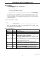
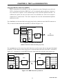
The Main E1 local analog loop back is performed by connecting the main link transmit
signal to the input of the receive path in analog mode, as shown in Figure 4-1. This
returns the transmit signal of each port on the receive path of the same port. Each channel
(including sub link) must receive its own transmission. This loop back fully tests the local
ETU02A-MUX operation and the connections to the local DTE. During this loop back,
the ETU02A-MUX main link sends an unframed “all ones” signal to the remote
equipment.
LOCAL ETU02A-MUX
User
DTE
CH1
CH2
“1”
CH3
E1
Transmission
CH4
MAIN LINK
SUB
LINK
Figure 4-1. Main E1 local analog loop back
28
ETU02A MAY 2000
CHAPTER 4. TEST and DIAGNOSTICS
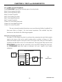
Main E1 local digital loop back
Main E1 local digital loop back is performed by connecting the main link receive signal to the
output of the transmit path in the digital mode. This loop back test checks the performance of the
local ETU02A-MUX, the remote ETU02A-MUX and the connections between them, as shown in
Figure 4-2.
LOCAL ETU02A-MUX
User
DTE
CH1
CSU
CH2
E1
Transmission
CH3
CH4
MAIN LINK
SUB
LINK
Figure 4-2. Main E1 local digital loop back
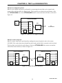
Main E1 remote loop back
Main E1 remote loop back is performed by sending the remote loop back code to the remote
CSU/DSU. The remote then enters digital loop back mode and the link is returned to the local unit.
This loop back test checks the performance of the local ETU02A-MUX, the remote unit and the
connections between them, as shown in Figure 4-3.
LOCAL ETU02A-MUX
CH1
REMOTE ETU02A-MUX
CSU
CSU
CH1
CH2
CH2
CH3
CH3
E1
Link
CH4
SUB
LINK
MAIN LINK
CH4
MAIN LINK
SUB
LINK
Figure 4-3. Main E1 remote loop back
29
ETU02A MAY 2000
CHAPTER 4. TEST and DIAGNOSTICS
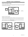
Sub E1 local digital loop back
Sub E1 local digital loop back is performed by connecting the sub link receive signal to the output
of the transmit path in digital mode, as shown in Figure 4-4. This loop back test checks the
connection to the equipment connected to the local sub link. The test signal is provided by the
equipment connected to the local sub link.
LOCAL ETU02A-MUX
User
DTE
CH1
CH2
E1
Transmission
CH3
CH4
SUB
LINK
E1
Transmission
MAIN LINK
Figure 4-4. Sub E1 local digital loop back
Sub E1 local analog loop back
Sub E1 local analog loop back is performed by connecting the sub link transmit signal to the input
of the receive path in analog mode, as shown in Figure 4-5. The test signal is provided by the
equipment connected to the remote sub link. During this loop back, the ETU02A-MUX sub link
sends an unframed “all ones” signal to the equipment connected to the local sub link.
LOCAL ETU02A-MUX
User
DTE
CH1
CH2
E1
Transmission
CH3
CH4
E1
Transmission
“1”
SUB
LINK
MAIN LINK
Figure 4-5. Sub link remote analog loop back
30
ETU02A MAY 2000
CHAPTER 4. TEST and DIAGNOSTICS
Sub E1 remote loop back
Sub E1 remote loop back is performed by sending the remote loop back code to the remote
CSU/DSU. The remote then enters digital loop back mode on the sub E1 and the link is returned to
the local unit. This loop back test checks the performance of the local ETU02A-MUX, the remote
unit and the connections between them, as shown in Figure 4-6.
LOCAL ETU02A-MUX
CH1
REMOTE ETU02A-MUX
CSU
CSU
CH1
CH2
CH2
CH3
CH3
E1
Link
CH4
SUB
LINK
MAIN LINK
CH4
MAIN LINK
SUB
LINK
Figure 4-6. Sub E1 remote loop back
Channel 1-4 local analog loop back.
Channel local analog loop back is performed by connecting the data channel transmit data (TD) to
the input of the receive path (RD) in analog mode, as shown in Figure 4-7. The test signal is
provided by the local DTE.
LOCAL ETU02A-MUX
User
DTE
CH2
E1
Transmission
CH3
CH4
SUB
LINK
MAIN LINK
Figure 4-7. Channel local analog loop back
31
ETU02A MAY 2000
CHAPTER 4. TEST and DIAGNOSTICS
Channel 1-4 local digital loop back.
Channel local digital loop back is performed by connecting the local data channel receive data (RD)
to the data channel transmit input (TD) in the digital mode, as shown in Figure 4-8. The test signal
is provided by the remote user DTE.
LOCAL ETU02A-MUX
User
DTE
CH1
CH2
E1
Transmission
CH3
CH4
SUB
LINK
CSU
Figure 4-8. Channel local digital loop back
Channel 1-4 remote loop back
Channel 1-4 remote loop back is performed by sending the remote loop back code to the remote
CSU/DSU. The remote then enters digital loop back mode on the selected channel and the link is
returned to the local unit. The test signal is provided by the local user DTE. This loop back test
checks the performance of the local ETU02A-MUX and connection to the DTE, the remote unit
and the connections between them, as shown in Figure 4-9.
LOCAL ETU02A-MUX
CH1
REMOTE ETU02A-MUX
CSU
CSU
CH2
CH2
CH3
CH3
E1
Link
CH4
SUB
LINK
MAIN LINK
CH4
MAIN LINK
SUB
LINK
Figure 4-9. Channel 1-4 remote loop back
32
ETU02A MAY 2000
CHAPTER 4. TEST and DIAGNOSTICS
Integrated Bit Error Rate Test (BERT).
BERT testing may be performed on only one channel at a time. During the test, the local
DTE is disconnected and the DSR line is off. An internal pattern generator connects a
user selected test sequence to the transmit input of the local data channel interface. To
calibrate the system, the user can inject errors at a selectable rate. The receive output is
connected to a pattern tester. The tester compares the received and transmitted patterns
and detects errors.
For a local test, use the main link local analog loop back (or hardwire main link RX connector to
TX), to return the data back to the local DTE, as shown in Figure 4-10.
LOCAL ETU02A-MUX
Generator
User
DTE
CH1
Tester
CH2
E1
Transmission
“1”
CH3
CH4
MAIN LINK
SUB
LINK
Figure 4-10. BERT for local test
(BERT on Channel 1, Main Link analog loop back.)
For a system test, use the remote loop back function or on the remote side use the main link digital
loop back, or data channel remote loop back, to return the data back to the local DTE, as shown in
Figure 4-11. Alternatively, run the BERT function from both sides using the same pattern type.
LOCAL ETU02A-MUX
REMOTE ETU02A-MUX
Generator
CH1
Tester
CSU
CSU
CH1
CH2
CH2
CH3
CH3
E1
Link
CH4
SUB
LINK
MAIN LINK
CH4
MAIN LINK
SUB
LINK
Figure 4-11. BERT used for system test
33
ETU02A MAY 2000
CHAPTER 4. TEST and DIAGNOSTICS
This page left blank intentionally.
34
ETU02A MAY 2000
APPENDIX A. DIP SWITCH SETTING
A-1 DSW1 SETTING
DSW1
-1
-2
-3
-4
-5
STATE
OFF
OFF
OFF
ON
ON
ON
ON
OFF
OFF
ON
OFF
ON
OFF
ON
FUNCTION
Control Port 9600 Baud
Control Port 2400 Baud
Control Port 4800 Baud
Control Port 19200 Baud
Reserved
Reserved
Reserved
Reserved
normal operation
interface port configuration
CONDITION
factory set
factory set
factory set
DSW1 is located on the main PC board.
A-2 SW1 SUB E1 LINE IMPEDANCE SETTING
DSW2
ALL
STATE
OFF
ON
FUNCTION
120 ohm balanced
75 ohm unbalanced
CONDITION
Factory setting
SW1 is located on the optional Sub Link interface card.
A-3 DSW2 MAIN E1 LINE IMPEDANCE SETTING
SW1
ALL
STATE
OFF
ON
FUNCTION
120 ohm balanced
75 ohm unbalanced
CONDITION
Factory setting
DSW2 are located on the main PC board.
A-4 JUMPER CHASS1 FRAME GROUND SETTING
CHASS1
ALL
STATE
DIS
CON
FUNCTION
Frame ground not connected to signal
Frame ground connected to signal ground
CONDITION
Factory setting
CHASS1 is located on the main PC board.
35
ETU02A MAY 2000
APPENDIX A. DIP SWITCH SETTING
This page left blank intentionally.
36
ETU02A MAY 2000
APPENDIX B. CONNECTORS
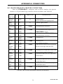
B-1. E1 LINE CONNECTORS
B-1.1 D-15 connector
The E1 link D-15 connector conforms to AT&T Pub 62411. The physical interface is a
15-pin female D-type connector.
Pin
Designation
Direction
Function
From ETU02A-MUX
Transmit data
↔
Frame ground
To ETU02A-MUX
Receive data
FG
↔
Frame ground
5
--
--
--
6
--
--
--
7
--
--
--
8
--
--
--
9
TRING
1
TTIP
2
FG
3
RTIP
4
From ETU02A-MUX
10 --
Transmit data
--
--
To ETU02A-MUX
11 RRING
Receive data
12 --
--
--
13 --
--
--
14 --
--
--
15 --
--
--
Table B-1 E1 D-15 connector pin allocation
B-1.2 BNC connector
Conn.
Pin
Designation
Direction
Function
TX
Center
TTIP
From ETU02A-
Transmit data
MUX
RX
Sleeve
TRING
↔
Signal return
Center
RTIP
To ETU02A-
Receive data
MUX
Sleeve
↔
RRING
Signal return
Table B-2 E1 BNC connector pin allocation
37
ETU02A MAY 2000
APPENDIX B. CONNECTORS
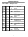
B-2. V.35 USER DATA CHANNEL CONNECTOR
Unless otherwise specified when ordering, the ETU02A-MUX data ports are all
factory configured for V.35 interface. When connecting the DB25 to MB34 adapter cable,
the physical interface is a 34-pin M-block type female connector wired in accordance
with Table B-3.
SIGNAL
FUNCTION
PIN
mux
PIN CIRCUIT
V.35
DIR.
DESCRIPTION
Protective
Ground
1
A
Frame
↔
Chassis ground. May be isolated from
signal ground.
Signal
Ground
7
B
Signal
Ground
↔
Common signal ground.
TD
2
14
P
S
TD(A)
TD(B)
To MUX Serial digital data from DTE.
RD
3
16
R
T
RD(A)
RD(B)
Fm MUX Serial digital data at the output of the
MUX receiver.
RTS
4
C
RTS
To MUX An ON signal to the MUX when data
transmission is desired.
CTS
5
D
CTS
Fm MUX Constantly ON.
DSR
6
E
DSR
Fm MUX Constantly ON, except during test loops.
DTR
20
H
DTR
To MUX Not used.
DCD
8
F
DCD
Fm MUX Constantly ON, except when a loss of the
received carrier signal is detected.
ETC
24
11
U
W
ETC(A)
ETC(B)
To MUX A transmitted data rate clock input from
the data source.
Transmit
Clock
15
12
Y TC(A)
AA TC(B)
Receive
Clock
17
9
External
Receive clock
?
?
Z ERC(A)
BB ERC(B)
To MUX A received serial data rate clock input
from the DTE.
Test Indicator
25
KK TM
Fm MUX ON during any test mode
V
X
RC(A)
RC(B)
Fm MUX A transmitted data rate clock for use by
an external data source.
Fm MUX A received data rate clock for use by an
external data source.
Table B-3. V.35 user data channel connector pin allocation
38
ETU02A MAY 2000
APPENDIX B. CONNECTORS
B-3. RS-530 USER DATA CHANNEL CONNECTOR
When the ETU02A-MUX is configured with an RS-530 interface, the physical
interface is a 25-pin female D-type connector wired in accordance with Table B-4.
SIGNAL PIN
FUNCTION
CIRCUIT
DIRECTION
DESCRIPTION
Protective
Ground
1
Frame
↔
Chassis ground.
May be isolated from signal ground.
Signal
Ground
7
AB
↔
Common signal ground.
Transmitted
Data
2 BA(A)
14 BA(B)
To MUX
Serial digital data from DTE.
Received
Data
3 BB(A)
16 BB(B)
Fm MUX
Serial digital data at the output of the
ETU02A-MUX receiver.
Request to
Sent
4 CA(A)
19 CA(B)
To MUX
A ON signal to the ETU02A-MUX when
data transmission is desired.
Clear to
Sent
5 CB(A)
13 CB(B)
Fm MUX
Constantly ON.
Data Set
Ready
6 CC(A)
22 CC(B)
Fm MUX
Constantly ON,
Except during test loops.
Data
Terminal
Ready
20 CD(A)
23 CD(B)
To MUX
DTR not used, used for a received serial
data rate clock input from the DTE.
Data Carrier 8 CF(A)
Detect
10 CF(B)
Fm MUX
Constantly ON, except when a loss of the
received carrier signal is detected.
External
Transmit
clock
24 DA(A)
11 DA(B)
To MUX
A transmitted data rate clock input from
the data source.
Transmit
Clock
15 DB(A)
12 DB(B)
Fm MUX
A transmitted data rate clock for use by an
external data source.
Receive
Clock
17 DD(A)
9 DD(B)
Fm MUX
A received data rate clock for use by an
external data source.
Test
Indicator
25 TM
Fm MUX
ON during any test mode
Table B-4. RS-530 user data channel connector pin allocation
39
ETU02A MAY 2000
APPENDIX B. CONNECTORS
B-4. RS-232 USER DATA CHANNEL CONNECTOR
When the ETU02A-MUX is configured with an RS-232 interface, the physical
interface is a 25-pin female D-type connector wired in accordance with Table B-5.
SIGNAL PIN CIRCUIT
FUNCTION
DIRECTION
DESCRIPTION
Protective
Ground
1
AA
↔
Chassis ground.
May be isolated from signal ground.
Signal
Ground
7
AB
↔
Common signal ground.
Transmitted
Data
2
BA
To MUX
Serial digital data from DTE.
Received
Data
3
BB
Fm MUX
Serial digital data at the output of the
ETU02A-MUX receiver.
Request to
Sent
4
CA
To MUX
An ON signal to the ETU02A-MUX when
data transmission is desired.
Clear to
Sent
5
CB
Fm MUX
Constantly ON.
Data Set
Ready
6
CC
Fm MUX
Constantly ON,
Except during test loops.
Data
Terminal
Ready
20 CD
To MUX
DTR not used, used for a received serial data
rate clock input from the DTE.
Data Carrier
Detect
8
CF
Fm MUX
Constantly ON, except when a loss of the
received carrier signal is detected.
External
Transmit
clock
24 DA
To MUX
A transmitted data rate clock input from the
data source.
Transmit
Clock
15 DB
Fm MUX
A transmitted data rate clock for use by an
external data source.
Receive
Clock
17 DD
Fm MUX
A received data rate clock for use by an
external data source.
Test
Indicator
25 TM
Fm MUX
ON during any test mode
Table B-5. RS-232 user data channel connector pin allocation
40
ETU02A MAY 2000
APPENDIX B. CONNECTORS
B-5. RS-530 to RS-449 ADAPTER CABLE
When the ETU02A-MUX is to be connected to an RS-449 device, the interface is
configured for RS-530 and an adapter cable is used. When connecting the DB25 to DB37
adapter cable, the physical interface is a 37-pin male D-type connector wired in
accordance with Table B-6.
SIGNAL
FUNCTION
RS530
PIN
RS449
PIN
RS-449
CIRCUIT
Protective
Ground
1
1
Signal
Ground
7
Transmitted
Data
2
14
4
22
SD(A)
SD(B)
Serial digital data from DTE.
Received
Data
3
16
6
24
RD(A)
RD(B)
Serial digital data at the output of the ETU02AMUX receiver.
Request to
Sent
4
19
7
25
RS(A)
RS(B)
A ON signal to the ETU02A-MUX when data
transmission is desired.
Clear to
Sent
5
13
9
27
CS(A)
CS(B)
Constantly ON.
Data Set
Ready
6
22
11
29
DM(A)
DM(B)
Constantly ON,
Except during test loops.
Data Terminal
Ready
20
23
12
30
TR(A)
TR(B)
DTR not used, used for a received serial data rate
clock input from the DTE.
Data Carrier
Detect
8
10
13
31
RR(A)
RR(B)
Constantly ON, except when a loss of the received
carrier signal is detected.
External
Transmit clock
24
11
17
35
TT(A)
TT(B)
A transmitted data rate clock input from the data
source.
Transmit
Clock
15
12
5
23
ST(A)
ST(B)
A transmitted data rate clock for use by an
external data source.
Receive
Clock
17
9
8
26
RT(A)
RT(B)
A received data rate clock for use by an external
data source.
Test Indicator
25
18
TM
ON during any test mode
Frame
19,20, SG,RC,
37 SC
DESCRIPTION
Chassis ground.
May be isolated from signal ground.
Common signal ground.
Table B-6. RS-530 to RS-449 pin allocation
41
ETU02A MAY 2000
APPENDIX B. CONNECTORS
B-6. RS-530 to X.21 ADAPTER CABLE
When the ETU02A-MUX is to be connected to an X.21 device, the interface is
configured for RS-530 and an adapter cable is used. When connecting the DB25 to DB15
adapter cable, the physical interface is a 15-pin female D-type connector wired in
accordance with Table B-7.
SIGNAL
FUNCTION
RS530
PIN
X.21
PIN
RS-449
CIRCUIT
DESCRIPTION
Protective
Ground
1
1
Shield
Chassis ground.
May be isolated from signal ground.
Signal
Ground
7
8
G
Common signal ground.
Transmitted
Data
2
14
2
9
T(A)
T(B)
Serial digital data from DTE.
Received
Data
3
16
4
11
R(A)
R(B)
Serial digital data at the output of the ETU02AMUX receiver.
Request to
Sent
4
19
3
10
C(A)
C(B)
A ON signal to the ETU02A-MUX when data
transmission is desired.
Data Carrier
Detect
8
10
5
12
I(A)
I(B)
Constantly ON, except when a loss of the received
carrier signal is detected.
External
Transmit clock
24
11
7
14
B(A)
B(B)
A serial data rate clock input from the data source.
Signal
Timing
15
12
6
13
ST(A)
ST(B)
A transmitted data rate clock for use by an
external data source.
Receive
Clock
17
9
8
26
RT(A)
RT(B)
A received data rate clock for use by an external
data source.
Test Indicator
25
15
TM
ON during any test mode
Table B-7. RS-530 to X.21 pin allocation
42
ETU02A MAY 2000
APPENDIX B. CONNECTORS
B-7. RS-232/ALARM PORT CONNECTOR
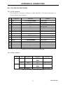
The ETU02A-MUX RS-232/ALARM port (craft port) has a standard RS-232 DCE interface
terminated in a 9-pin female D-type connector, wired in accordance with Table B-8.
Pin
RS-232 Function
Direction Connected to
Terminal
DB9
DB25
1
Data Carrier Detect
(DCD)
Output
1
8
2
Receive Data
(RD)
Output
2
3
3
Transmit Data
(TD)
Input
3
2
4
5
Alarm Relay function
Normally closed
(NC)
Signal Ground
5
7
6
Common contact
(COM)
7
Request To Sent
(RTS)
8
Clear To Sent
(CTS)
Input
7
4
Output
8
5
9
Normally open
(NO)
Table B-8 RS-232/ALARM port connector pin allocation
The alarm relay is activated during power loss or loss of signal on the Main or Sub E1.
43
ETU02A MAY 2000
APPENDIX B. CONNECTORS
This page left blank intentionally.
44
ETU02A MAY 2000
NOTES:
ETU02A-MUX TECHNICAL INQUIRY FORM
Attn : Technical Support Division
From Company:
Name:
Tel: (
)
Fax:(
)
MODEL: ETU02A-MUX/AC
ETU02A-MUX/DC
ACTIVITY: As attached in Parameter setting table
SYS CONFIGURATION:
Question:
ETU02A-MUX TECHNICAL INQUIRY FORM
45
ETU02A MAY 2000
NOTES:
46
ETU02A MAY 2000
CTC Union Technologies Co., Ltd.
Far Eastern Vienna Building
(Neihu Technology Park)
8F, No. 60 ZhouZi St.
Neihu, Taipei, Taiwan
Phone:(886) 2.2659.1021 Fax:(886) 2.2799.1355
E-mail: [email protected] http://www.ctcu.com