1
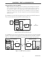
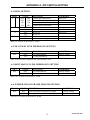
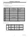
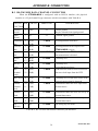
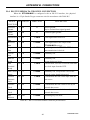
APPENDIX B. CONNECTORS
B-6. RS-530 to X.21 ADAPTER CABLE
When the ETU02A-MUX is to be connected to an X.21 device, the interface is
configured for RS-530 and an adapter cable is used. When connecting the DB25 to DB15
adapter cable, the physical interface is a 15-pin female D-type connector wired in
accordance with Table B-7.
SIGNAL
FUNCTION
RS530
PIN
X.21
PIN
RS-449
CIRCUIT
DESCRIPTION
Protective
Ground
1
1
Shield
Chassis ground.
May be isolated from signal ground.
Signal
Ground
7
8
G
Common signal ground.
Transmitted
Data
2
14
2
9
T(A)
T(B)
Serial digital data from DTE.
Received
Data
3
16
4
11
R(A)
R(B)
Serial digital data at the output of the ETU02AMUX receiver.
Request to
Sent
4
19
3
10
C(A)
C(B)
A ON signal to the ETU02A-MUX when data
transmission is desired.
Data Carrier
Detect
8
10
5
12
I(A)
I(B)
Constantly ON, except when a loss of the received
carrier signal is detected.
External
Transmit clock
24
11
7
14
B(A)
B(B)
A serial data rate clock input from the data source.
Signal
Timing
15
12
6
13
ST(A)
ST(B)
A transmitted data rate clock for use by an
external data source.
Receive
Clock
17
9
8
26
RT(A)
RT(B)
A received data rate clock for use by an external
data source.
Test Indicator
25
15
TM
ON during any test mode
Table B-7. RS-530 to X.21 pin allocation
42
ETU02A MAY 2000