1
CHAPTER 2. INSTALLATION
2-1. GENERAL
This chapter provides detailed instructions for mechanical installation of the
ETU02A-MUX. Following the completion of installation, please refer to Chapter 3 for
console port operating information.
2-2. SITE PREPARATION
Install the ETU02A-MUX within reach of an easily accessible grounded AC outlet.
The outlet should be capable of furnishing 90 to 250 VAC. Allow at least 10cm (4 inch)
clearance at the rear of the ETU02A-MUX for signal lines and interface cables.
2-3. MECHANICAL ASSEMBLY
The ETU02A-MUX is designed for tabletop, shelf or rack mount installation, and
except for rack mount installation, is delivered completely assembled. Rack mounted
applications require installation of additional rack mounting “ears”. No provisions are
made for bolting the ETU02A-MUX to the tabletop.
2-4. ELECTRICAL INSTALLATION
2-4-1. Power connection
AC power is supplied to the ETU02A-MUX through a standard IEC 3-prong plug.
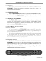
(Refer to Figure 2-1) The ETU02A-MUX should always be grounded through the
protective earth lead of the power cable.
The line fuse is in an integral-type fuse holder with the IEC power connector located
on the rear panel. Make sure that only fuses of the required rating are used for
replacement. Do not use repaired fuses or short-circuit the fuse holder. Always disconnect
the power cable before removing or replacing the fuse.
2-4-2. Rear panel connectors
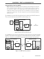
The data port channel interfaces (DCE) are accessible from the rear panel of the
ETU02A-MUX (Refer to Figure 2-1) and consist of DB25pin Female connectors. Direct
connections are allowed for RS-232 (SYNC) and RS-530. Adapter cables are required for
V.35, RS-449, and X.21. The E1 line and E1 sub-link connectors incorporate one
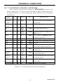
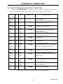
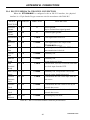
DB15pin each or two pairs of BNC Coax connectors. (Appendix B provides detailed
information on the various interface connectors).
Figure 2-1 ETU02A-MUX rear panel
11
ETU02A MAY 2000