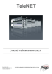
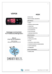
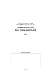
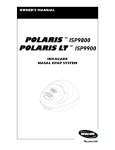
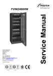
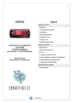
1
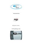
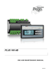
PLUS 300
EXPERT U THR
Use and maintenance manual
ENGLISH
READ AND KEEP
REV. 02-15
ENG
ELECTRICAL BOARDS FOR REFRIGERATING INSTALLATIONS
PLUS 300 EXPERT U THR
Thanks for choosing this PEGO electrical panel.
This manual gives detailed information on installation, use and maintenance of PLUS300
EXPERT U THR series electrical panels and special version. Our products are designed
and built in compliance with current standards, on the specific field of refrigeration and
conditioning systems. A different use is allowed respecting the working conditions for
which the panel is designed and made.
Before using the panel it’s suggested to fully read this manual paying special attention to
the highlighted parts with the simbology descripted below:
This symbol is used to focus on notes concerning installation, use and
maintenance operations
This symbol is used to focus on important notes
This symbol is used to indicate the prohibition to do the shown operation
Index
PLUS 300 EXPERT U THR
INDEX
INTRODUCTION
Pag.
Pag.
Pag.
Pag.
4
5
5
5
1.1
1.2
1.3
1.4
General
Product ID codes
Overall dimensions
Identification data
CHAP. 1
INSTALLATION
Pag.
Pag.
Pag.
Pag.
6
6
7
8
2.1
2.2
2.3
2.4
Important general information for the installer
Kit for mounting
installation
Functions managed by PLUS 300 EXPERT U THR
TECHNICAL SPECIFICATIONS
Pag. 9
3.1
Technical specifications
WARRANTY CONDITIONS
Pag. 10
4.1
Warranty conditions
CAP.
CHAP.
2 3
CHAP. 3
CHAP. 4
PARAMETERS PROGRAMMING
Pag.
Pag.
Pag.
Pag.
Pag.
Pag.
Pag.
Pag:
Pag.
Pag.
Pag.
Pag.
Pag.
Pag.
Pag.
Pag.
Pag.
Pag.
Pag.
Pag.
Pag.
Pag.
Pag.
11
11
12
14
14
14
15
15
17
17
20
22
23
23
24
25
25
26
26
26
27
27
29
5.1
5.2
5.3
5.4
5.5
5.6
5.7
5.8
5.9
5.10
5.11
5.12
5.13
5.14
5.15
5.16
5.17
5.18
5.19
5.20
5.21
5.22
5.23
Control panel
Frontal keyboard
LED display
General features
Key to symbols
Set point programming and displaying
First level programming
List of first level variables
Second level programming
List of second level variables
Automatic programs Pr1, Pr2, Pr3, Pr4, Pr5
Germination day/night cycle
Ignition of PLUS 300 EXPERT U THR electronic control
Cold/hot: preservation of ambient temperature
Humidity/dehumidification: preservation of ambient humidity
Ventilation
Air change
Pause
Defrost
Hot gas defrost
Funzione password
Automatic programs
Day/night cycle for germination lights
CHAP. 5
MAINTENANCE
Pag. 30
Pag. 31
6.1
6.2
General security rules
Maintenance
7.1
TeleNET monitoring/supervision system
CHAP. 6
OPTIONS
Pag. 31
CHAP. 7
DIAGNOSTIC
Pag. 32
8.1
CHAP. 8
Diagnostic
APPENDICES
Pag. 33
Pag. 34
A.1
A.2
EC declaration of conformity
100N master THR wiring diagram
Rev. 02-15
USE AND MAINTENANCE MANUAL
Pag. 3
CHAP. 1 - Introduction
PLUS 300 EXPERT U THR
CHAPTER 1: INTRODUCTION
GENERAL FEATURES
1.1
DESCRIPTION:
Three-phase electrical panel for temperature and humidity control for evaporating unit with
electrical heaters for hot.
To match with a compressor rack or a remote condensing unit.
Magnetothermic circuit breaker protection accessible from the front panel added to an
innovative form makes this panel a perfect and functional choice to provide safety,
protection, control of temperature and humidity with specific seasoning functions.
Programming up to five recipes, of seven phases each, settable and customizable (the
usable functions depend on the type of the panel).
Collectively the panel permits to control cold solenoid, condensing unit enabling, hot
heaters, ventilation (up to 800W), cold room light, humidification enabling, air exchange,
pauses, de-humidification, defrosts (up to 7500W), alarms.
APPLICATIONS:
-
Seasoning/drying rooms.
-
Germination rooms with day/night cycles.
-
Storage rooms with or without humidity control.
MAIN FEATURES:
-
Backlit LCD screen.
-
Clock and calendar.
-
Manual or automatic mode.
-
Up to 5 formula completely customazible automatic management of 7 phases for each
formula (dripping first phase, seasoning/conservation last phase). simple programming
and selection of set formula. possibility of join together more formula for exceeding the
7 phases limit.
-
Heat and humidity can be excluded to manage storage cells with defrost activation.
-
Temperature to one decimal point.
-
Password for keypad lock.
-
Day/night cycle for germination systems with double set-point.
-
Dehumidification program with cold or heat call.
Pag. 4
USE AND MAINTENANCE MANUAL
Rev. 02-15
CHAP. 1 - Introduction
PLUS 300 EXPERT U THR
PRODUCT IDENTIFICATION CODE
110P30EUTHR
1.2
Temperature and humidity control for
seasoning, preservation and industrial
processes.
DIMENSIONS
1.3
Dimensions in mm.
IDENTIFICATION DATA
1.4
The unit described in this manual has an ID plate on its side showing the relevant ID data:
• Manufacturer name
• Device code
• Serial number
• Date
• Power supply
• Frequency
• Rated current
• Protection (IP)
Rev. 02-15
USE AND MAINTENANCE MANUAL
Pag. 5
CHAP. 2 - Installation
PLUS 300 EXPERT U THR
CHAPTER 2: INSTALLATION
2.1
IMPORTANT GENERAL INFORMATION FOR THE INSTALLER
1. Install the device in places where the protection rating is observed and try not to
damage the box when drilling holes for wire/pipe seats;
2. Do not use multi-polar cables in which there are wires connected to inductive/power
loads or signaling wires (e.g. probes and digital inputs);
3. Do not fit power supply wiring and signal wiring (probes and digital inputs) in the same
raceways or ducts;
4. Minimize the length of connector wires so that the wiring does not have a spiral shape;
5. All wiring must be of a cross-section suitable for relevant power levels;
6. Place a general protection fuse upstream from the electronic controller;
7. When it is necessary to extend the probes, the wires must have a cross-section of at
least 1 mm². The probes extension or shortening could alter the factory calibration; then
check and calibrate through an external thermometer.
2.2
KIT FOR MOUNTING
PLUS 300 EXPERT U THR electronic controller kit, for assembling and using, contains:
• N° 4 seals, to be fitted between the fixing screws and the box back panel
• N° 1 use and maintenance manual.
• N° 1 electrical drawing.
• N° 1 drilling layout.
• N° 2 probes NTC 10K 1%
Pag. 6
USE AND MAINTENANCE MANUAL
Rev. 02-15
CHAP. 2 - Installation
PLUS 300 EXPERT U THR
INSTALLAZIONE QUADRO
2.3
• Raise the transparent cover that shields the magneto-thermal cut-out switch and remove
the screw cover on the right-hand side.
• Undo the 4 fixing screws at the front of the box.
• Open the front of the box, lift it and slide the two hinges out as far as they will go. Bend
the hinges and rotate the front panel by 180° downward to get access inside the panel
• Using the furnished drilling layout make four fixing holes on the wall.
Using holes made on previous point fix the bottom with 4 screws of a length suitable for
the thickness of the wall to which the panel will be attached. Fit a o-ring (supplied)
between each screw and the box backing
• Make all the electrical connections as illustrated in the diagram for the corresponding
model (see relative table in APPENDICES).
To effect correct electrical connection and maintain the protection rating, use appropriate
wire/raceway grips to ensure a good seal.
Route the wiring inside the unit in as tidy a fashion as possible: be especially careful to
keep power wires away from signal wires. Use clips to hold wires in place.
• close the front panel, making sure that all the wires are inside the box and that the box
seal sits in its seat properly.
Tighten the front panel using the 4 screws, making sure the O-rings on the head of each
screw are used.
Power up the panel and carry out thorough reading/programming of all the parameters.
• Be careful not to over-tighten the closure screws as this could warp the box and
compromise proper operation of the membrane-type keypad.
Install short-circuit overload safety devices on all the power cables connected to the
PLUS300 EXPERT U THR so as to prevent damage to the device. Work and/or
maintenance must ONLY be carried out on the unit after disconnecting the panel from the
power supply and from any inductive/power loads: doing so allows the worker to do his
job safely.
Rev. 02-15
USE AND MAINTENANCE MANUAL
Pag. 7
PLUS 300 EXPERT U THR
CAP. 2 - Installation
FUNCTIONS MANAGED BY PLUS 300 EXPERT U THR
2.4
• Display and adjustment of temperature and humidity settings (neutral zone)
• Stand-by activation/deactivation
• Sensor alarms
• Air change parameter adjustment
• Defrost parameter adjustment
• Pauses parameter adjustment
• Fan parameter adjustment
• Outputs status display
• Simultaneous display of temperature and humidity
• Automatic program control with automatic variation of temperature and humidity settings
over time.
• Clock function.
Pag. 8
USE AND MAINTENANCE MANUAL
Rev. 02-15
CHAP. 3 - Technical characteristics
PLUS 300 EXPERT U THR
CHAPTER 3: TECHNICAL CHARACTERISTIC
TECHNICAL CHARACTERISTICS
Technical characteristics
Box dimension
Weight
Protection rating
Power supply ( 3F + N + T )
Load type
Working temperature
Storage temperature
Relative ambient humidity
Reading range
Control
Status indicators
Main switch general protection
3.1
Plus 300 Expert U THR
400 x 300 x 135mm
6 Kg
IP65
400Vac ±10% 50/60Hz
three-phase
- 5 ÷ +40 °C
-25 ÷ +70 °C
Dal 30% al 90% RH without condensate
- 45 ÷ +45 °C / 0 ÷ 100% Rh
PEGO THR integrated
Display LCD
4 poles magnetothermic 20A
Inputs
Ambient probe
Evaporator probe
Humidity probe
Door switch
Min. temperature sensor
Max temperature sensor
NTC 10K 1%
NTC 10K 1%
4÷20mA (0 ÷ 100% Rh)
Present
Present
Present
Outputs
Enable condensing unit
Evaporator fans
Defrost
Hot heaters
Enable humidifiers
Enable dehumidifiers
Air change
Pause
Room light
Alarm relay
Supervision system
Present
800W (1ph)
Off-cycle
7500W (AC1)
Present
Present
Present
Present
Present
Present
TeleNET
Connection diagrams:
Rev. 02-15
USE AND MAINTENANCE MANUAL
Pag. 9
PLUS 300 EXPERT U THR
4.1
CHAP. 4 - Warranty conditions
WARRANTY CONDITIONS
PLUS300 EXPERT U THR series products are covered by a 24-month warranty against all
manufacturing defects as from the date indicated on the product ID code or from the date
of product registration card, if present.
In the event of a defect the product must be appropriately packaged and sent to our
factory or any authorized Service Center by authority RMA number received.
Customers are entitled to have defective products repaired, spare parts and labour
included. Transport expenses and risk shall be met entirely by the customer.
Repairs carried out under warranty do not prolong or renew the warranty expiration date.
The Warranty does not cover:
• Damages resulting from tampering, impact or improper installation of humidifier and
its accessories.
• Behaviour inconsistent with Manufacturer’s prescriptions and instructions.
• Damages caused by repairs made by unauthorized persons.
• Spare parts
• Damages caused by natural phenomena as lightning, natural calamities, etc.
Warranty cover may be refused if the device is modified or changed.
Under no circumstances Pego S.r.l. will be responsible for possible loss of data and
information, costs of substitutive goods or services, damages to things, people or animals,
non-sale or non-gain, activity interruption, possible direct, indirect, accidental, property,
covering, punitive, special or consequential damages anyhow caused, whether they are
contractual, extra-contractual or due to negligence or other responsibility, derived from
product use or from its installation.
The wrong machine working caused by manumissions, shoves, inadequate installation
automatically forfeits the warranty right. It is compulsory to respect all information of this
user manual and device operating conditions.
PEGO S.r.l. declines any responsibility for possible errors or inaccuracies written in this
manual as
a result of printing or transcription errors.
PEGO S.r.l. reserves the right to modify its products as it deems necessary without
altering its
main characteristics. Each new release of a PEGO user manual replaces all the previous
ones.
However not expressly indicated, the warranty follows the laws in force and particularly the
section 1512 C.C. (Italian Civil Code)
For any controversy is elected by the parties and recognized the jurisdiction of the Court of
Rovigo.
Pag. 10
USE AND MAINTENANCE MANUAL
Rev. 02-15
CHAP. 5 - Parameters programming
PLUS 300 EXPERT U THR
CHAPTER 5: PARAMETER PROGRAMMING
CONTROL PANEL
5.1
FRONTAL KEYBOARD
5.2
PROGRAM START/STOP (to press 5 sec for selecting the program to run,
to press 5 sec for finishing a running program)
TIMER (displays remaining time of running phase with a single key press)
UP
MANUAL PAUSE and DEFROST (activates both functions)
STAND BY ( system ON/OFF, the running program maintains the count of
remaining time)
SET ambient temperature and humidity (following pressures alternate
temperature and humidity)
Rev. 02-15
USE AND MAINTENANCE MANUAL
Pag. 11
CHAP. 5 - Parameters programming
PLUS 300 EXPERT U THR
DOWN / MUTE ALARM / FORCING AIR CHANGE
ROOM LIGHT
5.3
DISPLAY LED
1
PHASE 0 advancing/ Dripping / Day germination phase
2
PHASE 1 advancing
3
PHASE 2 advancing
4
PHASE 3 advancing
5
PHASE 4 advancing / Night germination phase
Pag. 12
USE AND MAINTENANCE MANUAL
Rev. 02-15
CHAP. 5 - Parameters programming
PLUS 300 EXPERT U THR
6
PHASE 5 advancing
7
Refreshment
8
Ambient temperature value/ parameters
Ambient relative humidity / parameters value / error codes
9
10
Time / date / time parameters value / running program / timer
11 PRG
Programming (the controller is in programming phase)
12
Cold (flashing if called for dehumidification only)
13
Hot (flashing if called for dehumidification only)
14
Humidification
15
Dehumidification
16
Defrost
17
Fans
18
Light (flashing if the door switch is active)
Rev. 02-15
USE AND MAINTENANCE MANUAL
Pag. 13
CHAP. 5 - Parameters programming
PLUS 300 EXPERT U THR
19
Alarm
20
Stand-by
GENERAL FEATURES
5.4
For safety reasons and to simplify the operator’s work, the PLUS 100 THR has two
programming levels; the first level is used to modify SETPOINT parameters (i.e. those
parameters that are changed frequently). The second level is for general parameter
programming of the various board work modes.
It is not possible to access the first programming level directly from the second level: you
must exit the programming mode first.
KEY TO SYMBOLS
5.5
For practical purposes the following symbols are used:
• (t) indicates the UP key
• (u) indicates the DOWN key
used to increase value and to force the defrost / pause;
used to decrease value, to mute the alarm and to force
the air changing.
5.6
SET POINT PROGRAMMING AND DISPLAYING
1. Push the SET key to display the current SET POINT (temperature and humidity
alternately).
2. Press the SET key and push one of (t) or (u) keys to modify the SET POINT value.
Release the SET key to return to cold room temperature display; modifications are saved
automatically.
Pag. 14
USE AND MAINTENANCE MANUAL
Rev. 02-15
CHAP. 5 - Parameters programming
PLUS 300 EXPERT U THR
FIRST LEVEL PROGRAMMING (User Level)
5.7
To access the first programming level proceed as follows:
1. Press the (t) and (u) keys simultaneously and keep them pressed for a few seconds
until the first programming variable appears on the display.
2. Release the (t) and (u) keys.
3. Select the variable to be modified using the (t) or (u) key.
4. When the variable has been selected it is possible:
• To display its setting by pressing SET
• To modify its setting by pressing the SET key and the (t) or (u) buttons.
When configuration values have been set you can exit the menu by pressing (t) and
(u) simultaneously for a few seconds until the room temperature value appears.
5. The modifications are saved automatically when you exit the configuration menu.
LIST OF 1ST LEVEL VARIABLES (User Level)
VARIABLES
dtC
dtF
dtn
dUU
dUd
dUn
d4
d5
d6
d7
MEANING
5.8
VALUES
DEFAULT
HOT temperature differential with reference to main
SET-POINT. It is expressed in absolute value and it defines
(dtn+0,2) ÷ 10 °C
the temperature hysteresis for the HOT referred to
temperature SET POINT.
COLD temperature differential with reference to main
SET-POINT. It is expressed in absolute value and it defines
(dtn+0,2) ÷ 10 °C
the temperature hysteresis for the COLD referred to
temperature SET POINT.
Temperature NEUTRAL zone with reference to main
SET-POINT. In neutral zone cold and hot are not activated;
dtF>dtn ÷ 0 °C
it includes symmetrically both a superior part (hot) and an
dtC>dtn ÷ 0 °C
inferior part (cold) as to temperature SET-POINT.
HUMIDIFICATION differential with reference to humidity
SET-POINT. It is expressed in absolute value and it defines
(dUn+1) ÷ 10
the humidification hysteresis referred to humidity SETrH%
POINT
DEHUMIDIFICATION differential with reference to
humidity SET-POINT. It is expressed in absolute value and it
(dUn+1) ÷ 10
defines the dehumidification hysteresis referred to humidity
rH%
SET-POINT .
Humidity NEUTRAL zone with reference to main
SET-POINT . In neutral zone humidification and
dUU>dUn ÷ 0
dehumidification are not activated; it includes symmetrically
rH%
both a superior part (humidification) and an inferior part
dUd>dUn ÷ 0
(dehumidification) as to humidity SET-POINT.
rH%
Defrost interval (hours). d4=0 disables the defrosts
0 ÷ 24 hours
Maximum lenght of defrost (minutes)
1 ÷ 60 min
End of defrost setpoint.
The defrost is not executed if the temperature read
from defrost probe is superior to d6 value.
-35 ÷ 45 °C
(In case of broken probe it will have a timing defrost)
Dripping duration (minutes)
At the end of defrosting, the compressor and the fans remain
0 ÷ 10 min
still for the d7 set time, the defrosting icon flashes.
Rev. 02-15
USE AND MAINTENANCE MANUAL
2 °C
2 °C
0 °C
5 rH%
5 rH%
0 rH%
0 hours
10 min
15°C
0 min
Pag. 15
PLUS 300 EXPERT U THR
CHAP. 5 - Parameters programming
rA1
…
rA6
Fans pause after defrosting (minutes)
Enables keeping the fans still for an F5 time after dripping.
This time starts from the end of dripping. If dripping is not
0 ÷ 10 min
set, at the end of defrosting the fans pause occurs directly.
Minimum temperature alarm
Enables defining a minimum temperature value to the
ambient. Below value At1, the alarm status will be signalled
-45 ÷ At2-1 °C
with the alarm icon flashing, the temperature flashes and an
internal buzzer acoustically signals the existence of an
anomaly. The alarm is signalled after the Ald time.
Maximum temperature alarm
Enables defining a maximum temperature value to the
ambient. Above value At2, the alarm status will be signalled
with the alarm icon flashing, the temperature flashing and an At1+1 ÷ 45 °C
internal buzzer acoustically signals the existence of an
anomaly. The alarm is signalled after the Ald time. The
alarm does not suspend any defrosting in progress.
Minimum humidity alarm
Enables defining a minimum humidity value to the ambient
to be humidified. Below the AU1 value, the Eu alarm status
1 ÷ AU2-1 Rh%
will be signalled with the alarm icon flashing and the buzzer
active. Silencing, the humidity and the alarm icon remain
flashing. The alarm is signalled after the Ald time.
Maximum humidity alarm
Enables defining a maximum humidity value to the ambient
to be humidified. Below the AU2 value, the Eu alarm status
will be signalled with the alarm icon flashing and the buzzer
AU1+1 ÷ 99 Rh%
active. By silencing, the humidity and the alarm icon remain
flashing.
The alarm is signalled after the Ald time. AU2=99 does not
signal the alarm.
Air change enabling in real time
0 = Disabled
With rA=1 it is possible to set up to 6 air changes in real time
1 = Enabled
during one day, through parameters rA1…rA6.
Air change times programming
It is possible to set up to 6 times for the air changes. The
00:00 ÷ 23:50
previous value blocks the subsequent one making them
sequential.
drA
Air change duration
tEu
Evaporator probe temperature display
(if dE =1 nothing is displayed)
F5
At1
At2
AU1
AU2
rA
Pag. 16
USE AND MAINTENANCE MANUAL
0 min
-45°C
+45°C
1 Rh%
99 Rh%
0
--
0 ÷ 10 min
6 min
temperature
only
reading
Rev. 02-15
CHAP. 5 - Parameters programming
PLUS 300 EXPERT U THR
SECOND LEVEL PROGRAMMING (Installer Level)
5.9
To access the second programming level press the UP (t) and DOWN (u) keys and the
LIGHT key simultaneously for a few seconds.
When the first programming variable appears the system automatically goes to stand-by.
1. Select the variable to be modified by pressing the UP (t) and DOWN (u) keys.
When the parameter has been selected it is possible:
2. To display the parameter setting by pressing the SET key.
3. To modify the parameter setting by pressing the SET key and pressing the (t) or (u)
key.
4. When setting has been completed you can exit the menu by pressing the (t) and
(u)keys
simultaneously and keeping them pressed until the cold room temperature reappears.
5. Modifications are saved automatically when you exit the configuration menu.
6. Press STAND-BY to enable electronic control.
LIST OF 2ND LEVEL VARIABLES (Installer Level)
VARIABLES
MEANING
AC
Microdoor input status (with door closed)
Pc
main alarm digital input status
F3
Fans status when cold, hot,
humidification and dehumidification are
at a stand-still
0 = Fans in continuous start
1 = Fans switched-off if cold,
hot, humidification and
dehumidification switched-off
1
F4
Fans pause during defrosting
0 = Fans working during
defrosting
1 = Fans not working during
defrosting
1
F6
Evaporator fans activation for air
recirculation. The fans activate for a time
defined by F7 if they have not started working
for the F6 time.
If activation time coincides with the defrosting
time, end of defrosting is awaited.
The speed of the fans (high/low) is the same
as that selected for the phase in progress.
Rev. 02-15
VALUES
5.10
0= usually open
1= usually closed
0 = NA
1 = NC
DEFAULT
0
0 = NA
0 – 240 min
0 min
0 =(function not activated)
USE AND MAINTENANCE MANUAL
Pag. 17
PLUS 300 EXPERT U THR
F7
F8
Pr
CHAP. 5 - Parameters programming
Evaporator fans duration for air
recirculation. Fans working time for F6
Fans speed during
seasoning/preservation . The value of
this variable is amended based on the setup made during the last phase of a
performed program.
Refreshment period.
Interval between one refreshment and the
subsequent one. The refreshment is a
work pause in which cold, hot, humidifies
and dehumidifies are disabled.
dr
Refreshment phase duration.
rin
K7 Multifunction relay function choice.
Ald
C1
dEU
Signal delay and alarm display time of
minimum or maximum temperature or
humidity.
Minimum time between switch-off and
subsequent ignition of the compressor.
It also stops the fans if they are not active
for other functions
Dehumidification method selection
The separate dehumidification calls hot
and cold only for temperature
0-240 sec.
0:00:10
0= High speed
1= Low speed
(only if rin=1)
0 ÷ 24 hours
(at 10 min steps)
0
0h
0 = Disabled
1 ÷ 240 min
120 min
0= Refreshment
1= Fans low speed
0
(1 min ÷ 4 hours)
240 min
0...15 min
0
0= cooling
1= heating
2= separate dehumidification
0= disabled
1= enabled
0= disabled
1= enabled
0
EnU
Humidification enabling
End
Dehumidification enabling
Cat
Ambient probe value correction
-10...+10
0
CaU
Humidity probe value correction
-20...+20
0
EnH
Hot enabling
Hr
Humidity management
dE
Evaporator probe exclusion
d1
Type of defrosting, at cycle inversion (hot
gas) or resistance. The compressor output
is also activated with hot gas
LSt
Minimum value attributable to setpoint
of temperature
Pag. 18
USE AND MAINTENANCE MANUAL
EnH= 1 hot enabled
EnH= 0 hot disabled
Hr= 1 enables humidity
management
Hr= 0 disables humidity
management The humidity
probe can be disconnected
without error on display.
The evaporator probe is
displayed instead of
humidity (if dE= 0)
=0 probe present
=1 probe absent
1
1
1
1
1
1= with hot gas
0= with resistance
0
-45 ÷ HSt °C
-45°C
Rev. 02-15
CHAP. 5 - Parameters programming
HSt
btF
btC
dEt
dEo
Ad
Aut
Cg
Maximum value attributable to setpoint
of temperature
Temperature differential referred to Setpoint
for COLD BLOCK.
It constitutes the SET-btF limit below which the
cold call relay and the dehumidification relay
are disabled.
Temperature differential referred to
Setpoint for HOT BLOCK.
It constitutes the SET+btC limit above
which the hot call relay , the humidification
relay and the dehumidification relay are
disabled.
Limit time for DEHUMIDIFICATION.
If the dehumidification request is not
satisfied (achievement of humidity SET)
within the time (dEt), the variable (dEO) is
taken into consideration for the operation
to be performed. Counting starts at every
new dehumidification request.
Operation to be performed in case Timeout
for dehumidification (dEt) intervenes
dEO= 0 an alarm signal (Ed) + buzzer +
alarm relay is given. The alarm is
displayed even when humidity set is
achieved; it does not block the normal
functioning and once silenced, the dEt
count re-starts.
dEO= 1 a refreshment of the duration (dr)
is launched and the timer relating to the
interval (Pr), if present, is recharged.
Indirizzo di rete per il collegamento al
sistema di supervisione TeleNET .
Automatic cycles management or via
TeleNET. For managing the cycles via
TeleNET to set Aut=1
Seasoning or germination selection
PLUS 300 EXPERT U THR
+45 ÷ LSt °C
+45°C
0 ÷ 20 °C
2
0 = Disabled
0 ÷ 20 °C
2
0 = Disabled
(0 min ÷ 4 hours)
(1 min steps)
0
0 = Disabled
0= alarm only
1= a refreshment is
performed.
0
0 ÷ 31
0
0 = local cycles
1 = TeleNET management
0
0 = seasoning cycles active
1 = germination day/night
cycle active
0
CgA
Not used.
0
0
tg2
Not used.
0
0
Rev. 02-15
USE AND MAINTENANCE MANUAL
Pag. 19
PLUS 300 EXPERT U THR
CHAP. 5 - Parameters programming
0= Total block. It is possible to
only see the temperature and
humidity set point.
P1
Password: type of protection.
(Active when PA is different from 0).
1= Blocks access in 1st and 2nd
level programmes.
Blocks access in germination
cycle amendment and
programmes amendment.
3
2=Blocks access in 1st and 2nd
level programmes.
3= Blocks access in 2nd level
programmes.
PA
Protection password
0 – 999
dMY
Current date
dd:mm:yy
HMS
Current time
0:00...23:59
reL
Software release
5.11
Shows the software release
(reading only)
6
AUTOMATIC PROGRAMS Pr1, Pr2, Pr3, Pr4, Pr5
To access the automatic programmes parameters, keep keys
START/STOP and
SET pressed for a few seconds (the function is active only if Cg=0).
1. Using key (t) or key (u) select the program to be amended. After having selected the
program, press the SET key to display the parameters.
2. Using key (t) or key (u) select the parameter to be amended.
3. Amend the setting by keeping the SET key pressed and by pressing one of the keys
(t) or (u).
4. Once configuration values have been set, to exit the menu press
keys (t) and (u) simultaneously keeping them pressed for a few seconds, until the
temperature value appears.
5. Memorisation of the amendments made to the variables will happen automatically when
exiting the configuration menu. Exiting from the menu happens spontaneously after an
inactivity period or by simultaneously pressing keys(t) and (u) for a few seconds.
The following table represents any one of the Pr1, Pr2, Pr3, Pr4, Pr5 programmes.
Pag. 20
USE AND MAINTENANCE MANUAL
Rev. 02-15
PLUS 300 EXPERT U THR
VARIABLES
MEANING
VALUES
DEFAULT
CIC=0 at the end of the last program
phase (phase 5) it moves to manual.
CIC
Sgt
SgU
CIC=1 at the end of the last timed phase
(phase 5) it returns to initial phase (phase
0). An infinite loop of the phases is
therefore created.
CIC=2 at the end of the last program
phase (phase 5) it moves on to the
subsequent program.
Phase 0 or dripping phase temperature
setpoint
Phase 0 or dripping phase humidity
setpoint
0= it ends the program and
moves on to manual.
1= loop phases
2= calls subsequent program
-45 ÷ +45°C
0...99 rH%
0= disabled
0= normal functioning
1= hot only enabled
2= hot, cold only enabled
Sg
Dripping enabling
Sgr
Refreshment
vSg
Dripping phase evaporator fans speed.
Amends the value of 2nd level variable
(F8)
tSg
Dripping phase duration
St1
Phase 1 temperature setpoint
SU1
Phase 1 humidity setpoint
rn1
Phase 1 refreshment
v1
Phase 1 evaporator fans speed. Amends
the value of 2nd level variable (F8)
t1
Phase 1 duration
St2
Phase 2 temperature setpoint
SU2
Phase 2 humidity setpoint
rn2
Phase 2 refreshment
v2
Phase 2 evaporator fans speed. Amends
the value of 2nd level variable (F8)
t2
Phase 2 duration
0
0= NO
1= YES
0= High speed
1= Low speed
(only if rin=1)
0:00...99:30
(30 min steps)
-45 ÷ +45°C
0...99 rH%
0= Disabled
0= NO
1= YES
0= High speed
1= Low speed
(only if rin=1)
0:00...99:30
(30 min steps)
-45 ÷ +45°C
0...99 rH%
0= Disabilitata
0= NO
1= YES
0= High speed
1= Low speed
(only if rin=1)
0:00...99:30
(at 30 min steps)
0
60%
0
0
0
0:00
0
60
0
0
0:00
0
60%
0
0
0:00
St3
Phase 3 temperature setpoint
-45 ÷ +45°C
0
SU3
Phase 3 humidity setpoint
0...99 rH%
0= Disabled
60%
Rev. 02-15
USE AND MAINTENANCE MANUAL
Pag. 21
CHAP. 5 - Parameters programming
PLUS 300 EXPERT U THR
rn3
Phase 3 refreshment
v3
Phase 3 evaporator fans speed. Amends
the value of 2nd level variable (F8)
t3
Phase 3 duration
St4
Phase 4 temperature setpoint
SU4
Phase 4 humidity setpoint
rn4
Phase 4 refreshment
v4
Phase 4 evaporator fans speed. Amends
the value of 2nd level variable (F8)
t4
Phase 4 duration
0= NO
1= YES
0= High speed
1= Low speed
(only if rin=1)
0:00...99:30
(30 min steps)
-45 ÷ +45°C
0...99 rH%
0= Disabled
0= NO
1= YES
0= High speed
1= Low speed
(only if rin=1)
0:00...99:30
(30 min steps)
0
0:00
0
60%
0
0
0:00
St5
Phase 5 temperature setpoint
SU5
Phase 5 humidity setpoint
rn5
Phase 5 refreshment
v5
Phase 5 evaporator fans speed. Amends
the value of 2nd level variable (F8)
t5
Phase 5 duration
St
Seasoning/preservation temperature
setpoint
-45 ÷ +45°C
0
SU
Seasoning/preservation humidity setpoint
0...99 rH%
0= Disabled
60%
tSC
Seasoning/preservation end timeout
0 ÷ 240 days
0
vSC
Seasoning/preservation evaporator fans
speed. Amends the value of 2nd level
variable (F8)
0= High speed
1= Low speed
(only if rin=1)
0
5.12
-45 ÷ +45°C
0
0...99 rH%
0= Disabled
0= NO
1= YES
0= High speed
1= Low speed
(only if rin=1)
0:00...99:30
(30 min steps)
0
60%
0
0
0:00
GERMINATION DAY/NIGHT CYCLE
To access the day/night cycle parameters for germination lights it is necessary to:
1. Check that parameter Cg=1
2. Keep keys
(u) DOWN and
LIGHT pressed for a few seconds.
3. Using key (t) or key (u) select the parameter to be amended.
4. Amend the setting by keeping the SET key pressed and by pressing one of the keys
(t) or (u).
Pag. 22
USE AND MAINTENANCE MANUAL
Rev. 02-15
CHAP. 5 - Parameters programming
PLUS 300 EXPERT U THR
5. Memorisation of the amendments made to the variables will happen automatically when
exiting the configuration menu. Exiting from the menu happens spontaneously after an
inactivity period or by simultaneously pressing keys(t) and (u) for a few seconds.
VARIABLES
tdS
tdE
MEANING
Day phase start time.
Germination lights active only during the
day phase.
Day phase end time.
tdE can also be < of tdS; for example, a
day phase can start at 10 pm and end at 4
pm of the following day.
VALUES
DEFAULT
00:00 ÷ 23:50
(10 min steps)
0
00:00 ÷ 23:50
(10 min steps)
0
00:00 ÷ 23:50
(10 min steps)
00:00 ÷ 23:50
(10 min steps)
tt1
t1 Temperature SET start time.
tt2
t2 Temperature SET start time.
t1
Temperature 1 SET.
-45 ÷ +45°C
0 °C
t2
Temperature 2 SET.
-45 ÷ +45°C
0 °C
0
0
IGNITION OF PLUS 100 THR ELECTRONIC CONTROL
5.13
After having wired the electronic controller, apply voltage 230 Vac; the control will
immediately and simultaneously emit a sound for a few seconds and remain fully switchedon on the display.
COLD/HOT: PRESERVATION OF AMBIENT TEMPERATURE
5.14
The cold and hot call is managed in neutral area depending on the set temperature
setpoint (
key 4) and to the temperature differentials (parameters dtC and dtF). The
cold is activated upon exceeding of set + dtF and remains active until set is achieved (with
dtn=0). The hot is activated below set - dtC and remains active until set is achieved (with
dtn=0).
It is possible to set a "dead area" with parameters dtn that deactivates hot and cold when
the temperature is between SET-dtn and SET+dtn.
Rev. 02-15
USE AND MAINTENANCE MANUAL
Pag. 23
PLUS 300 EXPERT U THR
CHAP. 5 - Parameters programming
Parameter C1 introduces a delay between a switch-off and the subsequent re-activation of
the cold. Hot can be deactivated with parameter EnH (EnH=0 disables the hot relay in all
conditions).
5.15
HUMIDITY/DEHUMIDIFICATION: PRESERVATION OF AMBIENT HUMIDITY
The humidity and the dehumidification call is managed in neutral area depending on the set
humidity setpoint (
key 4) and to the humidity differentials (parameters dUU and dUd).
Dehumidification is activated upon exceeding of set + dUd and remains active until set is achieved
(with dUn=0). Humidification is activated below set - dUU and remains active until set is achieved
(with dUn=0).
It is possible to set a "dead area" with parameters dUn that deactivates humidification and
dehumidification when humidity is between SET-dUn and SET+dUn.
The humidity management can be excluded with parameter Hr.
Dehumidification only can be excluded with parameter End.
Humidification only can be excluded with parameter EnU.
There are three dehumidification methods (parameter dEU):
1. Dehumidifies with the cold (the cold is called to dehumidify, the hot is added only to maintain
ambient temperature)
2. Dehumidifies with the hot (the hot is called to dehumidify, the cold is added only to maintain
ambient temperature)
3. Separate dehumidification (only the dehumidification output activates but hot and cold are not
called)
It is possible to give a maximum time for the dehumidification phase (parameter dEt) by signalling
an alarm or forcing a refreshment (parameter dEo)..
Pag. 24
USE AND MAINTENANCE MANUAL
Rev. 02-15
CHAP. 5 - Parameters programming
PLUS 300 EXPERT U THR
VENTILATION
5.16
The parameters of the second level programming F3, F4, F6, F7, F8 enable setting the
management of the fans in the different modes.
By setting parameter rin=1, it is possible to differentiate high and low speed of the fans in
the various phases of a program (parameters vSg, v1, v2, v3, v4, v5, vSC).
AIR CHANGE
5.17
The air changes can be enabled with parameter rA. Up to six daily execution times for air
change can be set in parameters from rA1 up to rA6.
The duration of the air change is defined by parameter drA.
During air change, hot, cold, humidity and dehumidification do not activate.
It is possible, at any time, to force an air change with the DOWN
Rev. 02-15
key.
USE AND MAINTENANCE MANUAL
Pag. 25
CHAP. 5 - Parameters programming
PLUS 300 EXPERT U THR
PAUSE
5.18
The refreshment is a phase of the pause process of the temperature and humidity
management. Refreshments are managed with parameters Pr and dr.
Pr defines the interval between one refreshment and the following one, dr defines the
duration of the refreshment.
It is possible, at any time, to force an air change with the UP
key. (a defrosting is
also simultaneously activated).
To interrupt a refreshment, position the control in stand-by (the times are reloaded).
DEFROST
5.19
Defrosting can be managed with parameters d4, d5, d6, d7, F5 that define the intervals,
the maximum duration, the defrosting end temperature, the dripping and the fans stop. To
manually activate defrosting it is sufficient to press the UP
key. Defrosting is not
activated in case the temperature set for defrosting end (d6) is lower than the temperature
detected by the evaporator probe. Defrosting will complete upon reaching the defrosting
end temperature (d6) or for defrosting maximum duration (d5).
HOT GAS DEFROST
5.20
Set parameter d1 = 1 for managing cycle inversion defrosting.
The compressor relay and the defrosting relay are activated for the entire defrosting
phase.
For the correct management of the plant, it will be the responsibility of the installer to use
the defrost output, that must allow the opening of the cycle inversion electrovalve and the
closing of the liquid electrovalve.
For the capillary plants (without thermostatic valve) it is sufficient to control the cycle
inversion electrovalve using the defrosting relay control.
Pag. 26
USE AND MAINTENANCE MANUAL
Rev. 02-15
CHAP. 5 - Parameters programming
PLUS 300 EXPERT U THR
PASSWORD FUNCTION
5.21
The password function activates by setting a value different from 0 for parameter PA. See
parameter P1 for the different protection levels.
Protection is enabled automatically after approx. 2 minutes of inactivity on the keyboard.
Numbers 000 appear on the display.
By keeping SET pressed, the first digit flashes for amendment using up/down arrow.
Release SET and press SET again: the second amendable digit flashes.
Release SET and press SET again: the third amendable digit flashes.
The operation is cyclical and therefore by pressing SET again, the first
digit flashes again, and so-on.
If password is forgotten use universal number 100.
AUTOMATIC PROGRAMS
5.22
An automatic program is a work cycle made of a maximum of 7 phases in which it is
possible to automatically amend the temperature and the humidity set point when passing
from one phase to the following one.
In each phase it is possible to choose whether to enable or not the movements (managed
with parameters Pr and dr) and manage a different speed for the fans.
It is possible to set up to 5 programmes (identified with Pr1, Pr2, Pr3, Pr4, Pr5) each of
which has a different setting according to the table of paragraph 5.10.
For each program, the first phase is defined dripping or phase 0; 5 process phases follow.
The last phase is the seasoning/preserving phase with unlimited duration in time.
Rev. 02-15
USE AND MAINTENANCE MANUAL
Pag. 27
CHAP. 5 - Parameters programming
PLUS 300 EXPERT U THR
Each phase and the dripping are characterised by:
Temperature setpoint
• Humidity setpoint
• Refreshments enabling/disabling
• High or low fans speed
• Phase duration (maximum 99 hours with 30 min steps)
For the dripping phase it is possible to exclude the humidity and the cold management.
The program starts by pressing the START key for a few seconds, the program selection
and, therefore, the pressing of the SET key.
Program start:
1) press the START
key for a few seconds
2) using the UP and DOWN arrows select the wanted program
3) press the SET
key to start the program
The time evolution is highlighted by the advancing bars. During program execution, it is
possible to amend the humidity and temperature setpoint directly from the keyboard
without having to access programming. Variations are provisional and do not alter the preset program.
If a phase has 0 time, it moves on to the following one.
The times of the phases proceed even in case of no electric power supply or control standby.
Using the START key (pressed briefly) it is possible to see the remaining time of the phase
in progress.
With parameter CIC, it is possible to program a cycle (once the program has finished it
automatically starts from the beginning) or to hook programmes between them, in order to
have a greater number of phases of the 6 of the individual program.
A program can always be interrupted by pressing the START/STOP
seconds.
Pag. 28
USE AND MAINTENANCE MANUAL
Rev. 02-15
key for a few
CHAP. 5 - Parameters programming
PLUS 300 EXPERT U THR
DAY/NIGHT CYCLE FOR GERMINATION LIGHTS
5.23
By setting parameter Cg (Germination/seasoning cycle) at second programming level, it is
possible to choose the use of the programmes or a special program suitable for day/night
cycles:
Cg = 0 (default) activates the automatic programmes management for seasoning;
Cg = 1 activates the management of the germination day/night cycle.
By means of the parameters indicated in paragraph 5.11, it is possible to determine the
day start and end times and manage two differential temperature setpoint.
During the day phase, the germination lights are switched on and the display
shows the references of phase 0 switched-on. During the night phase, the germination
lights are switched-off and the references of phase 4 switch-on.
The connection of the germination lights is separate from the cell light, that can be used as
service light (managed as usual from the microdoor and the light key).
The day/night cycle starts by pressing the cycle start key.
Rev. 02-15
USE AND MAINTENANCE MANUAL
Pag. 29
PLUS 300 EXPERT U THR
CHAP. 8 - Maintenance
CHAPTER 6: MAINTENANCE
GENERAL SECURITY RULES
6.1
For any type of maintenance , it must be exclusively executed by skilled technical staff.
In case of break down or maintenance to the electrical system, before
proceeding please cut off voltage to the panel placing general power supply
switch on open position (O). Check the absence of voltage with a tester
before doing any operation.
Each element of the panel, if defective, must be replaced only with original
spare parts.
If the intervention is on external parts of panel follow the next steps:
Switch off safely the panel power supply in one of the following ways:
1) Put 300 Expert main switch on OFF position and block it with a
mechanical block and then using a padlock.
2) Cut off power supply upstream the panel permanently, using a padlock
(on OFF position).
Place signals indicating maintenaince in progress.
Before proceeding with maintenance operations please follow these security
prescriptions:
The electrical panel must be without voltage.
Prevent the presence of unauthorized staff around the intervention area.
Positioning of suitable notices to signal "Device under maintenance".
Wear suitable and without free appendixes work cloths (overalls, gloves,
shoes, headgears).
Remove if worn, every object which can get entangled in any part of the
panel.
Suitable tools for the maintenance operations must be at disposal.
Tools must be correctly cleaned and greased.
Necessary technical documentation to execute maintenance intervention
must be at disposal (wiring diagrams, tables, drawings, etcc….)
At the end of the maintenance operations please remove all the residual
materials and make a careful cleaning inside the panel.
It’s absolutely forbidden to accomodate additional parts inside the panel.
The manufacturer declines every responsibility in case all the points
descripted in this chapter are not observed.
Pag. 30
USE AND MAINTENANCE MANUAL
Rev. 02-15
CAP. 8 - Maintenance
PLUS 300 EXPERT U THR
MAINTENANCE
6.2
The maintenance is necessary to ensure the electrical panel functionalities during the time
and to avoid that damaging of a few elements can put people in danger.
It must be done by skilled and authorized technical staff respecting the general security
rules
DEVICE
TYPE OF INTERVENTION
FREQUENCY
Terminal block
Wires tightening
After first 20 days of functioning
Wires tightening
Annual
Device screws
Terminal block
Device screws
CHAPTER 7: OPTIONAL KITS
TELENET MONITORING AND SUPERVISION SYSTEM
7.1
To insert the board in a TeleNET network, refer to the layout below. To configure the
instrument, refer to the TeleNET manual.
IMPORTANT: During configuration, select " PLUS 100 THR -R Controller " under the item
“Module”.
Rev. 02-15
USE AND MAINTENANCE MANUAL
Pag. 31
PLUS 300 EXPERT U THR
CHAPTER 8: DIAGNOSTIC
DIAGNOSTIC
8.1
In the event of a fault the PLUS 100 THR controller warns the operator by displaying an
alarm code and emitting a warning sound via the buzzer inside the control console.
If alarm conditions arise, the display will show one of the following messages:
ALLARM
CODE
POSSIBLE CAUSE
OPERATION TO BE PERFORMED
• Check the room temperature
sensor
• If the problem persists replace the
sensor
• Check the humidity sensor
• If the problem persists replace the
sensor
• Check the defrost sensor
• If the problem persists replace the
sensor
E0
Temperature sensor fault
E1
Humidity sensor fault
E2
Defrost sensor fault
(In this case eventual defrosts will last as d5)
E3
Eeprom alarm
An error in the EEPROM memory has been
detected.
(all output deactivated except the alarm ones)
E4
Software compatibility error
E6
Flat battery alarm
Ec
General alarm (e.g. overheat or max pressure
switch)
(All outputs, except alarm, if present, are
deactivated)
• Check compressor absorption
• If the problem persists, to contact
the technical assistance service
En
No connection between the Console and the
MASTER board.
• Check the connection between
the two units.
• If the problem persists, to contact
the technical assistance service
Eu
Minimum or maximum humidity alarm.
A humidity higher or lower to that set for minimum or • Check humidity management.
maximum humidity alarm has been reached in the
• The probe does not correctly
ambient (See variables AU1 and AU2, user
detect the humidity.
programming level)
Et
+
Temperature
on display is
flashing
Ed
Pag. 32
• Switch system off and back on
again
• Check for proper match between
MASTER board and console
board
• Replace lithium battery (CR2032
type) of the Console
Minimum or maximum temperature alarm.
•
A temperature higher or lower to that set for •
minimum or maximum temperature alarm has been
reached in the ambient (See variables At1 and At2,
user programming level)
Limit Timeout for dehumidification
USE AND MAINTENANCE MANUAL
Check the compressor status.
The probe incorrectly detects the
temperature or the stop/start
control of the compressor does
not work.
• Check humidity management.
• The probe does not correctly
detect the humidity.
Rev. 02-15
Appendices
PLUS 300 EXPERT U THR
APPENDICES
EC DECLARATION OF CONFORMITY
A.1
COSTRUTTORE / MANUFACTURER
PEGO S.r.l. Via Piacentina, 6/b 45030 Occhiobello (RO) – Italy –
Tel. (+39) 0425 762906 Fax. (+39) 0425 762905
DENOMINAZIONE DEL PRODOTTO / NAME OF THE PRODUCT
MOD.:
PLUS 300 EXPERT U THR
IL PRODOTTO E’ CONFORME ALLE SEGUENTI DIRETTIVE CE:
THE PRODUCT IS IN CONFORMITY WITH THE REQUIREMENTS OF THE FOLLOWING EUROPEAN DIRECTIVES:
Direttiva Bassa Tensione (LVD):
Low voltage directive (LVD):
2006/95/CE
EC/2006/95
Direttiva EMC:
Electromagnetic compatibility (EMC):
2004/108/CE
EC/2004/108
LA CONFORMITA’ PRESCRITTA DALLA DIRETTIVA E’ GARANTITA DALL’ADEMPIMENTO A TUTTI GLI EFFETTI
DELLE SEGUENTI NORME (comprese tutte le modifiche):
THE CONFORMITY WITH THE REQUIREMENTS OF THIS DIRECTIVE IS TESTIFIED BY COMPLETE ADHERENCE
TO THE FOLLOWING STANDARDS (including all amendments):
Norme armonizzate:
European standards:
EN 60730-1, EN 60730-2-9, EN 61000-6–1, EN 61000-6–3
EN 60730-1, EN 60730-2-9, EN 61000-6–1, EN 61000-6–3
IL PRODOTTO E’ COSTITUITO PER ESSERE INCORPORATO IN UNA MACCHINA O PER ESSERE ASSEMBLATO
CON ALTRI MACCHINARI PER COSTITUIRE UNA MACCHINA CONSIDERATE DALLA DIRETTIVA: 2006/42/CE
“Direttiva Macchine”.
THE PRODUCT HAS BEEN MANUFACTURED TO BE INCLUDED IN A MACHINE OR TO BE ASSEMBLED
TOGHETER WITH OTHER MACHINERY TO COMPLETE A MACHINE ACCORDING TO DIRECTIVE: EC/2006/42
“Machinery Directive”.
Rev. 02-15
USE AND MAINTENANCE MANUAL
Pag. 33
Appendices
PLUS 300 EXPERT U THR
100N Master PLUS 300 EXPERT U THR WIRING DIAGRAM
A.2
Power supply section
Outputs section (contacts without voltage)
1-2 Power supply 230VAC 50/60 Hz
21-22 Alarm
Analogical/digital inputs section
23-24 Defrosting
29-30 Evaporator NTC probe
25-26 Dehumidification
31-32 Humidity probe 4..20 mA (0100Rh%) (32=V+ 31=Y)
27-28 Ambient NTC probe
15-16 Refreshment (rin=0)/ low speed fans
(rin=1)
13-14 Air change
45-50 Stand by forcing
11-12 Humidification
44-50 Disables hot (forces variable
EnH=0)
43-50 Disables humidity (forces variable
Hr=0)
42-50 Microdoor
9-10 Cell light
5-6 Hot
41-50 Main alarm (stops all outputs)
3-4 Cold
35-36 - + 12V
TeleNET Section:
37-38 RS485 console
39 line A or clamp 3 of TWRS485
7-8 Fans (high speed if rin=1)
40 line B or clamp 4 of TWRS485
Pag. 34
USE AND MAINTENANCE MANUAL
Rev. 02-15
PLUS 300 EXPERT U THR
NOTES
Rev. 02-15
USE AND MAINTENANCE MANUAL
Pag. 35
PLUS 300 EXPERT U THR
PEGO S.r.l.
Via Piacentina, 6/b
Distributor:
45030 OCCHIOBELLO –ROVIGOPhohe: +39 425 762906
Fax: +39 425 762905
www.pego.it
USE AND MAINTENANCE MANUAL
e-mail: [email protected]
Pag. 36
Rev. 02-15