1
3--10
I/O Wiring and Specifications
Getting Started
I/O Module Wiring and Specifications
Module Placement
?
Before wiring the I/O modules in your
system to field devices, it’s very important
to make sure each I/O module is in the
right slot and base in the system. Costly
wiring errors may be avoided by doing the
following:
S
S
Perform the power budget calculations for each base to verify the base
power supply can power all the modules in the base.
Whenever possible, keep modules with high voltage and current wiring
away from sensitive analog modules.
NOTE: Please refer to the applicable Base Controller User manual for the power
budget requirements and worksheets.
I/O Wiring and
Specifications
I/O Module
Status Indicators
r
e
t
n
e
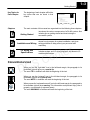
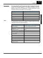
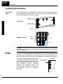
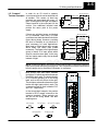
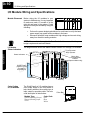
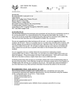
The diagram below shows the status indicator location for common I/O modules.
C
S
Status indicators
C
D
Display status
(selects a group
of signals to
be displayed)
Loose terminal
block indicator
Blown fuse
(non-replaceable)
indicator
(Output modules only)
Wire tray
Color Coding
of I/O Modules
The DL405 family of I/O modules have a
color-coded stripe on the front bezel to
help identify whether the module type is
input, output, or special module. The color
code description is listed below:
Module Type
Discrete/Analog Output
Discrete/Analog Input
Other
Color Code
Red
Blue
White
INPUT
110VAV
TB
A
Color Bar
å
B
0
4
0
4
1
5
1
5
2
6
2
6
3
7
3
7
D4--16NA
80--132VAC
80--20mA
50/60Hz
CA
0