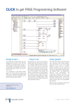
1
CLICK PLCs
Section 1
Section 2
DL105 PLC
Section 3
DL205 PLC
Section 4
DL305 PLC
Section 5
DL405 PLC
Section 6
• Click on part #s
to link directly to
our online store for
current pricing, specs,
stocking information
and more
.S o
,i
nly
red
rde
fo
w w w. a u to m at i o n d i re c t . c o m / d l 305
• Use bookmarks to
save, search, print
or e-mail the catalog
section
the U
Section 7
• Use bookmarks to
navigate by product
category
in
Available
Productivity3000
Programmable Controllers
DL05/06 PLC
In this interactive PDF
you can:
by
6p
m
ET.,
add
ition
al sh
ly.
ipping charges may app
Volume 14
e5-1
DL305 - Stay ahead by building on the past
What is it?
The DL305 series is a small modular PLC that has been marketed
by various name-brand PLC manufacturers for over 29 years. This
Koyo design revolutionized the small PLC market, and is still going
strong in tens of thousands of installations. If you subscribe to the
“If it ain’t broke, don’t fix it!” adage, be assured that you can
maintain your current system with fully compatible replacement
modules.
What’s it got?
• Three standard CPUs , including the D3-350 with PID control and two
communication ports
• Specialty CPUs to convert a DL305 system into an RTU for Optomux,
Pamux, or to allow BASIC programming for custom applications
• 5, 8 and 10-slot bases
• 110/220VAC or 24VDC power supply
• AC, DC inputs
• AC, DC, and relay outputs
• 8 or 12-bit analog input/output
• Specialty modules such as high-speed counter, and communication
interface module (work with D3-330 and D3-340 CPUs)
What can I do with it?
• Maintain or upgrade any installed GE Series One, Texas Instruments
Series 305, or Siemens SIMATIC TI305 system
• Build a system that meets Class I Division II classification
• Build RTU I/O stations for a host computer with a serial or parallel
interface
• Build an intelligent RTU that programs in the BASIC language
Siemens also called it the “Best Value
PLC”
In 1991, Siemens Industrial Automation decided to private label
the Koyo SR21 design. They named it the SIMATIC TI305 and
changed the color to charcoal grey. Once again, the product line
continued to receive enhancements and the nickname “Best Value
PLC” continued at Siemens.
AutomationDirect calls it a “PLC
Classic” and keeps it current
In 1994, AUTOMATIONDIRECT added more enhancements with
Windows-based DirectSOFT, and in 1997 introduced the D3-350
CPU, which offered updated features while maintaining compatibility.
Credibility in numbers
The Koyo DL305 design has been one of the most widely
marketed PLCs in history. Millions of modules have been sold,
proving that they are extremely reliable and well-suited for many
applications, and they cost less from us now than they ever did
from any of the guys who previously marketed this solid PLC line.
You can swap parts among all the PLCs
on the opposite page!
The DL305 PLC design has offered exceptional reliability, the right
mix of features and a great price. This design was so well-liked
when it was introduced that it became the most popular privatelylabeled PLC in history. Best of all, almost every part produced in its
27-year history is interchangeable.
GE nicknamed it “America’s Most
Popular PLC”
In 1983, General Electric decided to private label the Koyo SR21
design. They called it the General Electric Series One and
changed the color from Koyo yellow to black. The product sold so
well they nicknamed it “America’s Most Popular PLC.”
Texas Instruments called it the “Best
Value PLC”
In 1989, Texas Instruments began to private label the Koyo SR21
design. They named it the Series 305 and changed the plastic
color to light gray. The product was enhanced and did so well for
Texas Instruments that they nicknamed it the “Best Value PLC.”
Volume 14
e5-2
Programmable Controllers
1 - 80 0 - 633 - 0405
Company
Information
Systems
Overview
Programmable
Controllers
Field I/O
Software
C-more &
other HMI
Drives
Soft
Starters
Koyo Module
GE Module
Texas
Instruments
Module
Siemens
Module
PLC CPUS: DL305
CPU Feature
D3-330
D3-340
D3-350
Memory (words)
Local I/O
Remote I/O
RS-232C ports
Network master
MODBUS RTU
Built-in remote I/O
Real-time clock
PID
Floating-point math
Drum timers
3.7K
176
NO
1*
NO
NO
NO
NO
NO
NO
NO
3.7K
184
NO
2
YES
Slave
NO
NO
NO
NO
NO
14.8K
368
512**
2
YES
Master/slave
YES
YES
YES
YES
YES
Price
$308.00
$440.00
$335.00
Motors &
Gearbox
DirectLogic
D3-350 CPU
Steppers/
Servos
GE Base
Motor
Controls
Field tested
for over 29
years
Proximity
Sensors
Photo
Sensors
Limit
Switches
Encoders
Current
Sensors
Pressure
Sensors
Temperature
Sensors
* D3-DCU required ** Uses DL205 and DL405 remote slaves
Pushbuttons/
Lights
D3-350 CPU can bring your legacy
system up to date
Process
Relays/
Timers
Comm.
The D3-350 CPU has an expansive instruction
set (compatible with the DL405, DL205,
DL105, DL06 and DL05 families) and some
super practical communications. The D3-350
CPU can use a simplified I/O addressing
method, and can access up to twice as much
local I/O as any other DL305 configuration
(when installed in a system with “-1” bases).
Terminal
Blocks &
Wiring
Power
Circuit
Protection
Enclosures
Tools
Pneumatics
Safety
Order online or call 1-800-633-0405
for replacement modules
Appendix
Product
Index
Maintain or upgrade any installed GE Series One,
Texas Instruments Series 305, or Siemens SIMATIC TI305 system
Volume 14
w w w. a u to m a t i o n d i re c t . c o m / d l 305
Programmable Controllers
e5-3
Part #
Index
DL305 Family of Products
DL305 system example with serial communications network and
operator interface
OPC/DDE
Data Server
on PC
RS422
Business system
C-more panel
Industrial computer
Volume 14
e5-4
Programmable Controllers
1 - 80 0 - 633 - 0405
DL305 Family of Products
Company
Information
The following is a quick summary of the
DL305 family of products. The DL305
products have been sold by previous
vendors under a wide variety of part
numbers. A complete list of product offerings with vendor cross-reference is available in the DL305 price list.
Systems
Overview
Programmable
Controllers
Field I/O
Software
CPUs
C-more &
other HMI
D3-350 –14.8K total memory
2 communication ports
4 PID loops
MODBUS Master/Slave
Remote I/O
Floating point math
D3-340 – 3.7K total memory
2 communication ports
D3-330 – 3.7 K total memory
Drives
Soft
Starters
Motors &
Gearbox
Discrete input modules
Specialty modules
F3-OMUX-1
Serial interface to Optomux host
2 communication ports
(RS232C/422/485) selectable
DC Input
8-pt. 24VDC source
16-pt. 5V/12-24VDC (sink/source,1ms response)
16-pt. 24VDC source (0.8ms response)
8 pt. Input Simulator
Filler Module
F3-OMUX-2
Serial interface to Optomux host
2 communication ports
(RS422/485)
AC Input
8-pt. 110/220VAC
16-pt. 110 VAC
Specialty CPUs
F3-PMUX-1
Parallel interface to Pamux host
Bases
5-slot local or expansion base
Built-in 110/220 VAC power supply
5-slot local or expansion base
Built-in 24 VDC power supply
8-slot local base
(exp. base w/350 CPU)
Built-in 110/220 VAC power supply
10-slot local or expansion base
Built-in 110/220 VAC power supply
10-slot local or exp. base
Built-in 24 VDC power supply
AC/DC Input
8-pt. 24VAC/DC
16-pt. 24VAC/DC
Discrete output modules
DC Output
4-pt. 5-24VDC sink
8-pt. 5-24VDC sink
8-pt. 5-24VDC source
16-pt. 5-24VDC sink
16-pt. 5-24VDC source
AC Output
4-pt. 110-220VAC isolated
8-pt. 110VAC isolated
8-pt. 110-220VAC isolated
16-pt. 15-220VAC
RELAY Output
8-pt. 5.0A/pt
8-pt. 4.0A/pt isolated
8-pt. 10.0A/pt isolated
16-pt. 2A/pt
Analog modules
4 Channel IN, 12 bit, isolated
8 Channel IN, 12 bit
8 Channel thermocouple
16 Channel IN, 12 bit
4 Channel OUT 12 bit
4 Channel OUT 12 bit (isolated)
Steppers/
Servos
Motor
Controls
Proximity
Sensors
Photo
Sensors
Programming
Limit
Switches
Encoders
D3-HP Handheld Programmer for
D3-330/D3-340
D2-HPP Handheld Programmer with built-in
RLLPLUS for D3-350
DIN rail mounted
terminal blocks
See the Connection Systems section for over 200 available
options.
Communications
Data Comm Unit (RS232C), 330/340 CPUs only
Data Comm Unit (RS422), 330/340 CPUs only
Data Comm Module, 350 CPU only
Operator panels
See the Operator Interface section for a complete listing of all
types of panels and software.
Connection systems
See the Wiring Solutions section in this catalog for information on DINnector terminal blocks, ZIPLink connection systems and other connection accessories for use with the
DL305 system.
Current
Sensors
Pressure
Sensors
Temperature
Sensors
Pushbuttons/
Lights
Process
Relays/
Timers
Comm.
Terminal
Blocks &
Wiring
Power
Circuit
Protection
Enclosures
Tools
Pneumatics
Safety
Appendix
Product
Index
Volume 14
w w w. a u to m a t i o n d i re c t . c o m / d l 305
Programmable Controllers
e5-5
Part #
Index
DL305 CPUs
There are three conventional CPUs and
three specialty CPUs in the DL305 family.
There are many considerations for
choosing the right CPU, most of which
depend on your particular application.
The traditional CPUs, which offer control
via RLL-style programming, are great for
most applications. The information in this
section provides a quick comparison. If
you need to control I/O with a personal
computer, or if you want to run a BASIC
program in a CPU instead of ladder logic,
then check out the specialty CPUs.
D3-330 — The D3-330 design has been
very popular for many years. It offers the
lowest-cost solution in the DL305 family. It
is great for machines that need little (if any)
communications between the CPU and
other devices.
D3-340—The D3-340 offers a faster scan
rate, two RS232C ports (one with built-in
Modbus RTU slave) and additional I/O
points. Need RS422? Simply add an FAISOCON converter to one of the ports. If
you need built-in communications, or even
just an extra 16-point I/O card, the D3340 offers the lowest-cost solution. This
CPU allows you to make the most of your
investment in a DL305 (or compatible)
system.
D3-3 50—The D3-350 is the most
powerful DL305 CPU. It is a spin-off of
the D4-450 and D2-250(-1). It is plugcompatible with older bases, as well as
analog and discrete I/O modules. The
instruction set and I/O numbering scheme
are similar to our DL05, DL06, DL105,
DL205 and DL405 PLCs. The communications capabilities have also been greatly
enhanced to include RS422 Remote I/O,
MODBUS Master and Slave protocols, as
well as our own DirectNet and K-Sequence
protocols. When the D3-350 is installed
in a -1 base, even more features are available. These bases allow for greater I/O
expansion capabilities and for intelligent
I/O modules.
NOTE: D3-330 and D3-340 programs
cannot be downloaded into the D3-350
CPU. The D3-350’s instruction set is
based on the DL205/DL405 instruction
set. If an existing D3-330 or D3-340
system is upgraded to a D3-350 CPU, the
RLL program must be re-written for the
D3-350 CPU.
Volume 14
e5-6
Programmable Controllers
1 - 80 0 - 633 - 0405
CPU Specifications
Company
Information
Systems
Overview
DL305 CPU Specifications
System Capacity
D3-330
D3-340
D3-350
Total memory (K words)
Ladder memory (K words)
User data memory
CMOS RAM
UVPROM
EEPROM
Total I/O points using:
Local I/O
Local and Expansion I/O
Remote I/O1
I/O point density
Slots per base (CPU requires 1 slot)
3.91
3.7
116 bytes
Yes
Opt.
No
3.98
3.7
172 bytes
Yes
Opt.
Opt.
14.8
7.6
7.1K words
No
No
Flash
128
176
N/A
8/16
5/8/10
136
184
N/A
8/16
5/8/10
144
368
512
8/16
5/8/10
6.6µs
15ms
.87µs
4-5ms
.61µs
5-6ms
Yes
No
No
No
variable
Yes
No3
No
61
140
128
N/A
64
No
No
No
No
Yes
No
No
No
No
No
128
Yes
Yes
Yes
Yes
No
No
No
variable
Yes
2
No
63
196
128
N/A
64
No
No
No
No
Yes
No
No
No
No
No
192
Yes
Yes
Yes
Yes
Yes
Yes
Yes
either
Yes
2
Yes
129
1024
use CRs
1024
256/128
Yes
Yes
Yes
Yes
Yes
Yes
Yes
Yes
Yes
Yes
7168
Yes
Multi-level
Yes
Programmable
Controllers
Field I/O
Software
C-more &
other HMI
Drives
Soft
Starters
Performance
Contact execution (boolean)
Typical scan (1K boolean)2
Motors &
Gearbox
Steppers/
Servos
Programming & Diagnostics
RLL ladder style
RLLPLUS (stage)
RunTime Editing
Supports Overrides
Variable/fixed scan
Handheld programmer port
Built-in RS232C ports
Real-time clock/calendar
Instructions
Control relays(CR)
Shift register bits
Stages (RLLPLUS only)
Timers/counters
Immediate I/O
Subroutines
For/Next Loops
Timed interrupt
Integer math
Floating point math
PID
Drum sequence
Bit of word
ASCII print
Data registers
Internal diagnostics
Password security
Battery backup
Motor
Controls
Proximity
Sensors
Photo
Sensors
Limit
Switches
Encoders
Current
Sensors
Pressure
Sensors
Temperature
Sensors
Pushbuttons/
Lights
Process
Relays/
Timers
Communications
Built-in ports
DirectNET master
DirectNET slave
MODBUS RTU master
MODBUS RTU slave
Data communications unit
3
No
No
w/DCU
No
No
Yes
Yes
Yes
Yes
No
Yes
Yes
Yes
Yes
Yes
Yes
Yes
N/A
Yes
112
28
Yes
Yes
128
32
Yes
Yes
368
48
No
Comm.
Terminal
Blocks &
Wiring
Power
Specialty modules
Thermocouple
Analog Input (#channels max.)
Analog output (#channels max.)
High-speed counter (10KHz)
Circuit
Protection
1. The D3-350 bottom port supports DL205 remote I/O.
2. 1K program includes contacts, coils, and scan overhead. If you compare to other products, make sure to
include their scan overhead.
3. The D3-330 requires a Data Communications Unit
(DCU) for programming with DirectSOFT software.
Enclosures
Tools
Pneumatics
Safety
Appendix
Product
Index
Volume 14
w w w. a u to m a t i o n d i re c t . c o m / d l 305
Programmable Controllers
e5-7
Part #
Index
D3-350 CPU
D3-350
<--->
Our most powerful
DL305 CPU
Easily connect programming devices
The D3-350 combines the power, speed
and ease of the D2-250-1 CPU with
existing DL305 I/O modules and bases.
D i r e c t S O F T Pr o g r a m m i n g Software
Release V2.3 or higher is required to
program the D3-350. For existing license
holders, an upgrade package is available.
If you are using a handheld programmer
(D2-HPP, release 1.8 or lower), a new
release of handheld programmer firmware
will also be required.
Four PID loops
and auto-tuning
The D3-350 CPU can process up to four
PID loops directly in the CPU. Select from
various control modes, including automatic, manual and cascade control. There
are a wide variety of alarms including
Process Variable, Rate of Change and
Deviation. The loop operation parameters
(Process Variable, Setpoint, Setpoint Limits,
etc.) are stored in V-memory, which allows
easy access from operator interfaces or
HMIs.
Setup is accomplished with easy-to-use
setup menus and monitoring views in our
DirectSOFT Programming Software.
Or
Master station
issuing network request
Powerful built-in CPU
communications
Or connect operator
interfaces
The D3-350 offers two communication
ports that provide a vast array of communication possibilities. The top RS232C port
is for programming, a DV-1000 connection, a connection to our operator interDirectNET
face panels, or a K-sequence/D
slave port. The 25-pin bottom port can use
RS232C or RS422. This port offers several
different protocol options, such as
K-sequence protocol, DirectNET Master/Slave, Modbus Master/-Slave, and even a
direct connection to DL205 remote I/O.
The ability to select these features is
provided via software so you can choose
the best combination for the application.
Modbus or DirectNet
protocols
C-more panel
Slave stations responding
to network devices
The auto-tuning feature is also easy to use
and can reduce setup and maintenance
time. The CPU uses the auto-tuning
feature to automatically determine near
optimum loop settings.
Note: D3-330 and D3-340 programs
cannot be downloaded into the D3-350
CPU. The D3-350’s instruction set is
based on the DL205/DL405 instruction
set. If an existing D3-330 or D3-340
system is upgraded to a D3-350 CPU, the
RLL program must be re-written for the D3350 CPU.
C-more or DV-1000
D3-350 CPU
Setpoint
Value
Control
E quation
DL305 Analog Input
Modules
Process
Variable
Input
DL305
Analog Output or
Discrete Output
Control
Output
Control
E lement
(valve, etc.)
Process
(heater,
etc.)
P I D Loop Control
Block Dia gra m
Process
Variable
S ensor
Volume 14
e5-8
Programmable Controllers
1 - 80 0 - 633 - 0405
D3-350 Key Features
Company
Information
The D3-350 supports over 130 instructions. These include:
• Four types of drum sequencers
• Leading and trailing edge triggered oneshots
• Bit of word manipulation
• Floating point conversions
• Print instruction to send ASCII data
through the bottom CPU port
CPU Status Indicators
Built-in remote
I/O connection
ON
OFF
CPU is in RUN mode
CPU is in Program mode
Programmable
Controllers
BATT
ON
OFF
Battery backup voltage is low
Battery backup voltage is OK or disabled
Field I/O
ON
OFF
CPU internal diagnostics has detected
an error
CPU is OK
ON
OFF
CPU power good
CPU power failure
PWR
Forces CPU into Run Mode
TERM
Allows peripherals (HPP, DirectSOFT and operator interface panels) to write to the CPU.
STOP
Forces CPU out of RUN mode
0V
RS 422 RXD+
RS 422 RXD-RS 422 CTS +
RE MIO TXD+
RE MIO TXD--
RS 422 TXD+
RS 422 TXD-RS 422 RTS -RS 422 RTS +
K-sequence slave
Protocols DirectNET slave
Devices
Can connect w/HPP, DirectSOFT, DV-1000,
C-more Panels, or any DirectNET Master
Specs.
6P6C phone jack connector
RS232C
9600 baud
Odd parity
Fixed station address 1
8 data bits 1 start, 1 stop bit
Asynchronous, half-duplex, DTE
RS 422 CTS -RE MIO RXD+
25 RE MIO RXD--
The bottom port on the D3-350 can also
be used as a master for a remote I/O
network. If you need extra I/O at some
remote distance from the CPU, use this
port to add up to seven DL205 remote
slave stations. (See the DL205 section for
D2-RSSS information.)
Port 2
Steppers/
Servos
Proximity
Sensors
Photo
Sensors
Limit
Switches
Encoders
Current
Sensors
K-sequence slave
DirectNET Master/slave
Pressure
Sensors
Remote I/O Master
Temperature
Sensors
Protocols MODBUS RTU Master/slave
Devices
Can connect w/many devices, such as PCs running DirectSOFT, KEPddirect for PLCs Server, HMI
packages, DV-1000, C-more panels, or any
DirectNET or MODBUS RTU master or slave
Specs.
25-pin D-shell connector
RS232C/RS422
300/600/1200/2400/4800/9600
19.2K/38.4K Baud
Odd, even or no parity
Selectable address
(1-90, HEX 1-5A)
8 data bits-1 start, 1 stop bit
Asynchronous,half-duplex,DTE
Built-in Remote I/O master
Motors &
Gearbox
Motor
Controls
P ort 2
1
C-more &
other HMI
Soft
Starters
RUN
Port 1
RS 232 TXD
RS 232 RXD
RS 232 RTS
RS 232 CTS
Software
Drives
Mode Switch
On-board
flash memory
The D3-350 has 7.6 K of flash memory on
board. With flash memory, you don’t have
to worry about losing the program due to
a bad battery. If you have critical data
stored in V-memory, like PID loops, simply
purchase the optional lithium battery to
maintain these parameters as well.
RUN
CPU
For a complete list of instructions
supported by the D3-350 CPU, see the
end of this section.
Systems
Overview
Batteries (optional)
only, coin type 3.0V Lithium battery,
D2-BAT-1 D3-350
560mA battery # CR2354
Note: Batteries are not needed for program backup.
However, you should order a battery if you have parameters in V-memory that must be maintained in case of
a power outage, such as PID loops.
Pushbuttons/
Lights
Process
Relays/
Timers
Comm.
Terminal
Blocks &
Wiring
Power
Circuit
Protection
Enclosures
Tools
Pneumatics
Safety
Appendix
…allows you to connect up to seven DL205 remote slaves!
Product
Index
Volume 14
w w w. a u to m a t i o n d i re c t . c o m / d l 305
Programmable Controllers
e5-9
Part #
Index
D3-350 PID Loop Specifications
PID Loop Specifications and Key Features
Number of Loops
Selectable, four maximum
CPU V-Memory Required
32 V-memory locations per loop selected (additional 32 V-memory locations per loop
required if using Ramp/Soak)
PID Algorithm
Position or velocity form of the PID equation. direct or reverse acting, square root of the
error and error squared control.
Auto Tuning
Open-loop step response method and closed-loop limit cycle method.
Sample Rate
Specify the time interval between PV samples, 0.05 to 99.99 seconds. Smallest sample rate
is limited to either 0.05 seconds or (PLC scan time x number of loops).
Loop Operation Modes
Loops can be in automatic control, manual (operator) control, or cascade control. PV alarm
monitoring continues when loops are in manual mode.
Ramp/Soak
Up to 16 steps (8 ramp, 8 soak) per loop, with indication of ramp/soak step.
Square Root PV
Specify a Square root of the PV for a flow control application.
Limit SP
Specify a maximum and minimum value for allowable setpoint changes.
Limit Output
Specify a maximum and minimum value for the output range.
Gain
Specify proportional gain of 0.01 to 99.99.
Reset
Specify integral time of 0.1 to 999.8 in units of seconds or minutes.
Rate
Specify the derivative time, 0.00 to 99.99 seconds.
Rate Limiting
Specify a derivative gain limiting coefficient to filter the PV used in calculating the derivative
term (0 to 20).
Bumpless Transfer I
Bias and setpoint are initialized automatically when the module is switched from manual to
automatic. This provides for a bumpless transfer, which reduces the chance of sharp
changes in the output as a result of entering automatic mode.
Bumpless Transfer II
Bias is set equal to the output when the module is switched from manual to automatic. This
allows switching in and out of automatic mode without having to re-enter the setpoint.
Error Deadband
Specify an incremental value above and below the setpoint in which no change in output is
made.
Error Squared
Squaring the error minimizes the effect a small error has on the Loop output, however both
Error Squared and Error Deadband control may be enabled.
Alarm Specifications
Deadband
Specify 0.1% to 5% alarm deadband on all alarms except rate of change.
PV Alarm Points
Specify PV alarm settings for low-low, low, high, and high-high conditions. You can also
specify a deadband to minimize the alarm cycles when the PV approaches alarm limits.
PV Deviation
Specify alarms to indicate two ranges of PV deviation from the setpoint value (yellow and
red deviation).
Rate-of-Change
Specify a rate-of-change limit for the PV.
Volume 14
e5-10
Programmable Controllers
1 - 80 0 - 633 - 0405
D3-330 and D3-340 Key Features
D3-330
D3-340
<--->
<--->
DL330
The diagram to the right shows the
various hardware features found on the
D3-330 and D3-340 CPUs.
Company
Information
Systems
Overview
LED
indicators
BATT
Peripheral port
(HP, DCU,
UVPROM writer)
CP U
CPU Status Indicators
RUN
ON
OFF
CPU is in RUN mode
CPU is in Program mode
BATT
ON
OFF
Memory backup voltage low
Memory backup voltage good
CPU
ON
OFF
CPU failure
CPU is good
PWR
(Power)
ON
OFF
CPU power good
CPU power failure
Port1
RED
RX/TX
GREEN
(D3-340)
Flashing red indicates the CPU port is
receiving data
Flashing green indicates the CPU port
is sending data
Port2
RX/TX
(D3-340
Flashing red indicates the CPU port is
receiving data
Flashing green indicates the CPU port
is sending data
RED
Green
EEPROM and UVPROM
chips
The DL305 CPUs come with on-board
RAM and a battery. If you need additional
program security, you may want to choose
the EEPROM or UVPROM memory.
D3-CPU-UV <---> Optional
UVPROM memory. Four chips per pack.
(Only one chip is required for the CPU.)
A D3-PWU Prom Writer Unit is required
for programming.
D3-340-EE <--->
Optional EEPROM memory for the D3340 only. Four chips per pack. (Only one
chip is required for the CPU.) No additional programming device is necessary.
P WR
R UN
P ORT1
TX/R X
BATT
P ORT2
TX/R X
CP U
Field I/O
Software
F IXE D
Network address
mode switch
C-more &
other HMI
US E R
Drives
RS232C
Communication Ports
-DirectSOFT
-DirectNET
-Operator interfaces
P OWER
P IN
Number S ignal
R XD
1
TXD
2
RTS
3
GND
4
Soft
Starters
Motors &
Gearbox
PRG
R S 232C
Steppers/
Servos
Motor
Controls
D3-340 RS232C Communication Port Specs
GND
CTS
RTS
TXD
R XD
Hardware switches
Proximity
Sensors
Protocol
DirectNET
Connector
Network address
RJ11(handset connector)
01 to 90
Baud rate
38400, 19200, 9600, 4800, 2400, 1200, 600, 300
Parity-
None or odd
Transfer mode
HEX/ASCII
Half-duplex
Asynchronous
Data bits
Start bits
Stop bits
8
1
1
Turn around delay
0 to 1980 in 20ms intervals (preset with R777)
Below is a side view of a D3-340 CPU
that shows several types of hardware
switches.
The D3-330 has a 2-position dipswitch
for selecting retentive memory and
jumpers for selecting UVPROM and RAM
options.
Photo
Sensors
Limit
Switches
Encoders
Current
Sensors
The D3-340 has a jumper switch for
selecting UVPROM, EEPROM and RAM
options, two rotary switches to select
network addresses and an eight-position
dipswitch for selecting baud rates (300 to
38.4K baud), communication mode
(slave, master, Modbus RTU) and memory
options.
D3-D4-BAT <--->
Spare battery (lithium 3.0V). Also used
for D4-430 and D4-440 CPUs.
Programmable
Controllers
DL340
R UN
Address range
Pressure
Sensors
Temperature
Sensors
Pushbuttons/
Lights
Process
Relays/
Timers
Comm.
Terminal
Blocks &
Wiring
Power
SW4
Circuit
Protection
SW3
Enclosures
Ports
R AM/UVP R OM
Most significant
digit for address
Least significant
digit for address
Tools
Pneumatics
Safety
Appendix
Battery
Product
Index
Volume 14
w w w. a u to m a t i o n d i re c t . c o m / d l 305
Programmable Controllers
e5-11
Part #
Index
DL305 Specialty CPUs
Your application may require an unconventional PLC solution. For instance, you
may need computer-controlled I/O (the
PLC I/O is controlled directly by your
personal computer), or maybe you would
like a PLC that executes a control program
written entirely i n B A S I C i n s t e a d o f
R L L . AUTOMATIONDIRECT offers three
specialty CPUs that provide solutions for
each of these applications.
Computer I/O CPUs
Three CPUs are available for the DL305
family that allow DL305 I/O (with DL305
bases) to function as computer-controlled
I/O.
These
CPUs
(F3-OMUX-1,
F3-OMUX-2 and the F3-PMUX-1) are
similar in functionality, but offer different
communication options. Each CPU allows
DL305 modules of most types (see restrictions on types) to be interfaced with a host
computer. The entire control program for
the DL305 I/O is executed on the host
computer, which uses an OPTOMUX or
PAMUX driver.
I/O module
restrictions
The specialty CPUs can make use of
almost all DL305 modules, but they do not
support the D3-HSC, or D3-02DA
modules. These modules can only be used
with the regular CPUs (D3-330 and
D3-340).
F3-OMUX-1 <--->
F3-OMUX-2 <--->
The F3-OMUX (-1, -2) CPU plugs into the
first slot of a DL305 base. It acts as
a serial interface to the control
program in the host computer and
up to 184 DL305 I/O per CPU.
Multiple CPUs can be daisychained together to increase I/O
count. The host computer must use
an OPTOMUX serial communication driver. The host can execute a
custom program or use a standard
software
package
that
supports
OPTOMUX drivers such as IntouchWonderware, Iconics-Genesis, U.S. Data
FactoryLink, Metra-Skyhawk Lt, etc.
µp
General Specifications
•Two serial ports that support the
OPTOMUX protocol
F3-OMUX –1
RS232C/RS422/RS485
F3-OMUX-2
RS422/RS485 (isolated)
•Max of 184 I/O points per CPU (with
expansion base unit)
•Scan time is dependent on the communication speed, number of commands sent, type of commands
sent, the size of the response and
the speed of the host computer.
µp
F3-PMUX-1 <--->
The F3-PMUX is similar in operation
to
the
F3-OMUX
(-1, -2). It uses a parallel interface instead of serial interface.
As a result, it requires the host
computer to use a PAMUX
communication board (OPTO 22
part number AC28 or equivalent). With this board, you can use PAMUX
communication drivers in your host software. Scan time constraints are similar to
the OMUX units.
The –1 version has a 26Mhz processor and replaces
the F3-PMUX CPU.
The following charts show the various
features found on the DL305 specialty
CPUs:
F3-OMUX-n
Communication port specifications
Interface
Connector
Baud Rate
Protocol
Bridg e CPU
F3-OMUX-1
Host computer
F3-OMUX-1
µp
F3-OMUX-1: RS232C/422
F3-OMUX-2: RS422/485 (isolated)
Two 9-pin D-sub sockets (female)
Port 1: 300, 1200, 2400, 4800,
9600, 9200, 38400, 57600, 115200
Port 2: 9600
OPTO 22 serial communications
Control program resides
in host computer
OPTOMUX or
PAMUX protocol
F3-PMUX-1
Communication port specifications
Interface
Connector
Protocol
Parallel
50-pin ribbon cable connector
OPTO 22 parallel communications
Bridge CPU
F3-PMUX-1
F3-PMUX-1
F3-OMUX and F3-PMUX
CPUs read and write to
DL305 I/O as requested
by host computer
Volume 14
e5-12
Programmable Controllers
1 - 80 0 - 633 - 0405
Communications
Determine your
communications
requirements
Standard
communications
The choice of CPU can have a big impact
on your communications capabilities in
the DL305 family. If you are considering
doing any communications, you should
use the D3-340 or the D3-350 CPUs.
You can communicate with the D3-330
CPU, but you have to add a DL305 Data
Communications Unit to connect any
device other than a handheld
programmer. The Data Communications
Unit has only one port.
D3-340 RS232C Communication Port
Specifications
Protocol
DirectNET
Connector
Network address
RJ11(handset connector)
01 to 90
Baud rate
38400, 19200, 9600, 4800,
2400, 1200, 600, 300
Parity-
None or odd
Transfer mode
HEX/ASCII
Half-duplex
Asynchronous
Data bits
Start bits
Stop bits
8
1
1
Turn around delay
0 to 1980 in 20ms intervals
(preset with R777)
CPU with built-in
communication ports
Connect to either
port RS232C
The D3-340 and D3-350 CPUs offer two
built-in RS232C communication ports.
Operator interfaces and DirectSOFT can
be connected to either port. On the
D3-340 CPU, the handheld programmer
is attached directly or with a cable to the
parallel port adjacent to the two serial
communication ports. On the D3-350
CPU, the handheld programmer is
attached to Port 1. The handheld
programmer can be operated simultaneously with the communication ports. The
D3-340 baud rate and network
addresses are set by hardware
dipswitches and rotary switches for Port 1.
Port 2 uses internal registers that can be
changed with a handheld programmer or
DirectSOFT. Port 1 on the D3-350 is
fixed. Port 2 can be configured using the
handheld programmer or DirectSOFT.
DL305 as a slave
on a network
Both ports on the D3-340 and the
D3-350 CPUs can serve as slave ports for
DirectNET. The bottom ports offer additional flexibility in that they can serve as a
slave on a Modbus RTU network. The D3350 even supports RS422, so no RS232to-RS422 converter is needed. No
programming is required in these CPUs
for them to act as slave ports.
Company
Information
DL305 as a
network master
Systems
Overview
The bottom built-in communication port
of the D3-340 and D3-350 CPUs can
serve as a Network Master for DirectNET.
Up to 90 slave stations can be addressed.
The D3-350 can also serve as a
MODBUS RTU Master; up to 247 slave
stations can be addressed. DL405,
DL305 and DL205 controllers can be
used as slave stations. (Please note there
are certain restrictions pertaining to valid
DL205 and DL405 memory types that the
D3-340 master can read and write.)
Custom drivers
The DL305 product family supports the
DirectNET protocol. However, in some
applications you may have a need to
connect to a device that does not support
this protocol. If so, the ASCII/BASIC
modules also allow you to write your own
custom communication drivers (in BASIC)
to connect to special devices. These highspeed modules offer communication
rates up to 115.2K baud on RS232C,
RS422, and RS485. With 128K of
memory, there is ample program or data
storage space. (These modules are not
supported by the D3-350.)
Programmable
Controllers
Field I/O
Software
C-more &
other HMI
Drives
Soft
Starters
Motors &
Gearbox
Steppers/
Servos
Motor
Controls
Proximity
Sensors
Photo
Sensors
Limit
Switches
Encoders
Current
Sensors
Pressure
Sensors
Temperature
Sensors
Pushbuttons/
Lights
Process
Relays/
Timers
Handheld programmer
Comm.
Terminal
Blocks &
Wiring
Power
Network Addresses
Port
Protocol
Range
1
Slave
1-90
Slave
1-90
Master
0
MODBUS/RTU
1-247
2
Circuit
Protection
DL205/305/405 slaves
FA-UNICON
FA-ISOCON
Enclosures
FA-UNICON
Tools
D2-240
D3-340
Pneumatics
D4-430/440/450
Safety
Appendix
Product
Index
Volume 14
w w w. a u to m a t i o n d i re c t . c o m / d l 305
Programmable Controllers
e5-13
Part #
Index
I/O Selection
Choose your
I/O modules
There are three major factors to consider
when choosing an I/O module:
Environmental specifications:
What environmental conditions will be
present?
Hardware specifications:
Does this product have the right features,
performance and capacity to adequately
serve the application?
General I/O module specifications
Specification
Discrete module specifications sheet example
D3-08TA-1 AC Output
Field termination:
How does this module connect to field
devices? For DC modules, is a sinking or
sourcing module required?
Specifications
Environmental
specifications
The adjacent table lists the environmental
specifications that globally apply to the
DL305 system (CPU, Bases, and I/O
modules). Be sure the modules you
choose are operated within these environmental specifications.
Review I/O
hardware
specifications
The hardware specifications for every
DL305 module are listed with each
module. Discrete module specifications
are shown in a format similar to the
example to the right. Take time to understand the specification chart, the derating
curve and the wiring diagram.
Specialty module specifications are shown
in a format that is relevant for each particular module. These module specifications
should help you determine if this module is
right for your application.
Rating
Storage temperature . . . . . . . . . . . . . . . . . . . . . . . . . . . . . . . . . . . . . . -4°F – 158°F (-20°C to 70°C)
Ambient operating temperature . . . . . . . . . . . . . . . . . . . . . . . . . . . . . 32°F – 140°F (0° to 60°C)
Ambient humidity . . . . . . . . . . . . . . . . . . . . . . . . . . . . . . . . . . . . . . . . 5% - 95% relative humidity (non-condensing)
Vibration resistance . . . . . . . . . . . . . . . . . . . . . . . . . . . . . . . . . . . . . . MIL STD 810C, Method 514.2
. . . . . . . . . . . . . . . . . . . . . . . . . . . . . . . . . . . . . . . . . . . . . . . . . . . . Shifting:
0.075mm 10~57Hz 3 Axes
. . . . . . . . . . . . . . . . . . . . . . . . . . . . . . . . . . . . . . . . . . . . . . . . . . . . Acceleration:
9.8 m/s2 57-150Hz 3 Axes
. . . . . . . . . . . . . . . . . . . . . . . . . . . . . . . . . . . . . . . . . . . . . . . . . . . . Sweeping:
810C, Method 516.2
Peak accel. . . . . . . . . . . . . . . . . . . . . . . . . . . . . . . . . . . . . . . . . . . . . . 147 m/s2 11ms, 3 Axes
Noise immunity. . . . . . . . . . . . . . . . . . . . . . . . . . . . . . . . . . . . . . . . . . NEMA (ICS3-304)
Atmosphere . . . . . . . . . . . . . . . . . . . . . . . . . . . . . . . . . . . . . . . . . . . . No corrosive gases
Derating curve
Outputs per module
8
Commons per module
2 (isolated)
Operating voltage
80-265VAC
Output type
TRIAC
Peak voltage
265VAC
AC frequency
47-63Hz
ON voltage drop
1.5 VAC @ 1A
Max current
1A/point 3A/common
Max leakage current
1.2mA @ 220VAC
0.52mA @ 110VAC
Max inrush current
10A for 16ms 5A for 100ms
Minimum load
25mA
Base power required
9V 20mA/ON pt.
(160 MA Max) 24V N/A
OFF to ON response
1ms Max
ON to OFF response
8.33ms Max
Terminal type
Removable
Status indicators
Logic Side
Weight
7.4oz. (210g)
Fuses
2 (one 5A per common) Non-replaceable
Derating Chart
Points
8
0.5A
6
1A
4
110--220VAC OUTP UT
D3--08TA--1
2
0
1
2
3
0
0
32
10
20
30
40
50
50
68
86
104 122
Ambient Temperature (˚C/˚F )
60 ˚ C
140 ˚ F
4
5
6
7
INTE R NALLY CONNE CTE D
0
80--265VAC
L
0
C1
L
Module wiring
C1
L
C1
L
C1
80--265VAC
C
1
1
2
3
1
2
3
NC
NC
L
4
C2
L
C2
L
C2
L
5
4
6
7
C
2
C2
INTE R NALLY CONNE CTE D
5
6
7
80--265VAC
Common
Typical circuit
9V
5A
L
Output
Volume 14
e5-14
Programmable Controllers
1 - 80 0 - 633 - 0405
I/O Selection
Factors affecting field
termination
Sinking and sourcing for DC field devices:
If you are using a DC type of field device,
then you should consider whether the
device is a sinking or sourcing configuration. This may affect your module selection since it determines the manner in
which the device must be wired to the
module. (Both sinking and sourcing
modules are available.) Refer to the
sinking/sourcing section of the Appendix
for a complete explanation of how this
could affect your system.
Ph ys ical wire te rmination s: In general,
DL305 modules use five types of field
terminations. They include: removable
terminal blocks (included on most 8 and
16-point modules), fixed terminal blocks;
specialty D-sub connectors (used on a few
16-point modules), standard D-sub
connectors (used on most specialty intelligent modules), and phone jack style (used
on the D3-340 CPU, some specialty
modules and the universal cable kit). The
module descriptions indicate the
connector type that is on the module. The
following illustrations shows these types of
connectors. You can also use our DIN
rail-mounted terminal blocks, DINnectors,
or ZIPLink cables as a field termination
interface to the PLC and I/O modules.
Choose your modules
Now that you understand the factors that
affect your choice of an I/O module, it’s
time to choose ones that best suit your
needs. When you have selected the
modules, proceed to the next section to
choose an I/O configuration scheme that
best suits your application.
ZIPLink Connection System
If your application requires a lot of relay
outputs, consider using the ZIPLink AC or
DC relay output modules. These modules
can switch high current (10A) loads
without putting a load on your base power
budget. Refer to the Terminal Blocks and
Wiring Solutions section in this catalog for
more information.
This logo is placed next to the I/O
modules that are supported by the ZIPLink
connection systems. See the I/O module
specifications at the end of this section.
Removable terminal block
Extra connectors
or spare fuses
There are several types of spare parts that
may be useful. A filler module provides a
quick and easy way to cover empty slots.
Or, it is sometimes helpful to have extra
I/O module connectors or spare fuses.
Also, keep in mind the DINnector family
which provides DIN rail-mounted terminal
blocks for simplifying and organizing your
wiring needs.
• F3-FILL-CB – Filler module for empty slots
<--->
• D3-16IOCON – 16pt. I/O terminal blocks
<--->
• D3-8IOCVR – 8pt. I/O terminal plastic covers
<--->
• D3-16IOCVR – 16pt. I/O terminal
plastic covers
<--->
• D3-IODSHEL – 24-pin D-shell connectors
<--->
• D3-FUSE-1- Fuses for D3-05B, D3-08B,
and D3-10B
<--->
• D3-FUSE-2 – Fuses for D3-04TAS
<--->
• D3-FUSE-3 – Fuses for D3-05BDC and
D3-10BDC
<--->
• D3-FUSE-4 – Fuses for D3-08TAS,
D3-08TAS-1, F3-16TA-1 and F3-16TA –2
<--->
• D3-FUSE-5 – Fuses for D3-08TR
<--->
• D3-FUSE-6 – Fuses for F3-08TRS-2
<--->
• D3-ACC-1 – Base power terminal
strip screws
<--->
• D3-ACC-2 – Spare terminal screws
for 8pt. I/O modules
<--->
• D3-ACC-3 – Spare terminal screws for 16pt.
I/O modules
<--->
ZIPLinks
eliminate the tedious
process of wiring PLC I/O
terminal blocks.
Company
Information
Systems
Overview
Programmable
Controllers
Field I/O
Software
C-more &
other HMI
Drives
Soft
Starters
Motors &
Gearbox
Steppers/
Servos
Motor
Controls
Proximity
Sensors
Photo
Sensors
Limit
Switches
Encoders
Current
Sensors
Pressure
Sensors
Temperature
Sensors
Pushbuttons/
Lights
Process
Relays/
Timers
Comm.
Terminal
Blocks &
Wiring
Power
Circuit
Protection
Enclosures
Tools
Pneumatics
Safety
Fixed terminal block
Appendix
Squeeze tabs
Product
Index
Volume 14
w w w. a u to m a t i o n d i re c t . c o m / d l 305
Programmable Controllers
e5-15
Part #
Index
DL305 I/O Configuration
Local I/O – Local I/O are the modules
that reside in the same base as the CPU.
The status of each I/O point is updated
on each I/O scan of the CPU.
Local e xpansion I/O – Most local CPU
bases can be expanded to include expansion I/O. Local expansion is commonly
used when there are not enough I/O
points available in the existing base
configuration or the power budget
maximum for the existing base will be
exceeded with the addition of I/O. This
configuration requires an additional
base(s) and an I/O expansion cable(s).
The CPU treats the expanded I/O in the
same manner as local I/O, with updates
every CPU I/O scan. There are certain
addressing restrictions that are related to
expansion I/O.
Remote I /O – (D3-350 CPU only) –
Remote I/O is used when you need to
place I/O bases at some remote distance
from the CPU base. There are certain
restrictions that are related to remote I/O.
Check the catalog section on DL205
Remote I/O for examples and additional
information.
I/O Configuration Limitations
D3-340/
D3-350
D3-330
D3-350 with -1
bases
(AC powered only)
5-slot Local CPU Base System
64 I/O max
64 I/O max
64 I/O max
5-slot Local CPU Base System with a
5-slot Expansion Base
120 I/O max
128 I/O max
144 I/O max
5-slot Local CPU Base System with two
5-slot Expansion Bases
120 I/O max
128 I/O max
224 I/O max
8-slot Local CPU Base System
112 I/O max
112 I/O max
112 I/O max
8-slot Local CPU Base System with a
5-slot Expansion Base
152 I/O max
152 I/O max
192 I/O max
8-slot Local CPU Base System with an
8-slot Expansion Base
N/A
N/A
240 I/O max
8-slot Local CPU Base System with an
8-slot Expansion Base & 5-slot Expansion
Base
N/A
N/A
320 I/O max
8-slot Local CPU Base System with two
8-slot Expansion Bases
N/A
N/A
368 I/O max
10-slot Local CPU Base System
128 I/O max
136 I/O max
144 I/O max
10-slot Local CPU Base System with a
5-slot Expansion Base
168 I/O max
176 I/O max
224 I/O max
10-slot Local CPU Base System with a
10-slot Expansion Base
176 I/O max
184 I/O max
304 I/O max
Note: The 16-point modules must be in the first eight slots adjacent to the CPU, rolling over into an expansion
base if necessary.
Example of I/O system with expansion I/O
Expansion I/O
Local I/O
The I/O modules used and local base size
determine expansion capability. See the
addressing restrictions later in this section.
DL305 base
D3-EXCBL
1.5 ft (0.5m)
expansion cable
DL305 base
Volume 14
e5-16
Programmable Controllers
1 - 80 0 - 633 - 0405
I/O Module Locations
The design of the DL305 has a successful
29-year history. Each time the product
family has grown or been enhanced,
compatibility with the earlier products has
been preserved to protect customer investments. This has resulted in an I/O
numbering system and I/O location
scheme that has some special requirements.
The Module Placement Guideline table
explains the rules that pertain to module
location. Some specialty modules have
additional requirements. These are
explained in their respective module data
sheets. Remember that the power budget
will limit the location where some modules
can be placed in a base.
Company
Information
Systems
Overview
Module Placement Guidelines
Programmable
Controllers
Device
Placement
CPU
•The CPU must reside in the first slot of the local CPU base (closest to the power supply).
•The CPU slot does consume an I/O slot. For example, a D3-05B-1 5-slot base has a slot
for the CPU and 4 slots for I/O modules.
16 Point I/O Modules
A maximum of eight 16-point modules may be installed in a system. However, the actual
number allowed depends on the type of CPU you are using.
D3-330- maximum of seven 16-pt. modules
D3-340/350 - maximum of eight 16-pt. modules
D3-350 - w/-1 base can have 16-pt. modules in all available slots
Note: some specialty modules, such as the High Speed Counter and Thumbwheel Interface Unit, require 16 points
and are treated as 16-point modules.The 16-point modules must be in the first 8 slots adjacent to the CPU. They
may roll over into an expansion base if necessary. If any of the 8 slots adjacent to the CPU are not used for 16point modules, they can be used for 8-point modules.
Analog
Analog modules must reside in any valid 16-point I/O module slot.
ASCII BASIC Modules
ASCII BASIC modules can be placed in any valid 16-point I/O slot.
(D3-350 does not support these modules)
High Speed Counter
A High-Speed Counter must be used in the first four I/O module slots in the local CPU base.
(D3-350 does not support these modules)
Field I/O
Software
C-more &
other HMI
Drives
Soft
Starters
Motors &
Gearbox
Steppers/
Servos
Motor
Controls
I/O Points Usage Table for Modules
Proximity
Sensors
The following table indicates the number of I/O points that are used by each module. Use this information to ensure your I/O configuration stays within the valid I/O count of your chosen CPU.
Photo
Sensors
DC Input
DC Output
Relay Output
D3-08ND2
8
D3-04TD1
4
D3-08TR
8
D3-16ND2-1
16
D3-08TD1
8
F3-08TRS-1
8
D3-16ND2F
16
D3-08TD2
8
F3-08TRS-2
8
D3-16ND3
16
D3-16TD1-1
16
D3-16TR
16
D3-16TD2
16
Specialty Modules
AC Input
D3-08NA-1
8
AC Output
D3-08SIM
8
D3-08NA-2
8
D3-04TAS
4
D3-DCM
0*
D3-16NA
16
F3-08TAS-1
8
Analog
D3-08TA-1
8
F3-04ADS
16
AC/DC Input
D3-08NE3
8
D3-08TA-2
8
F3-08AD-1
16
D3-16NE3
16
F3-16TA-1
16
F3-08THM-n
16
F3-16TA-2
16
F3-16AD
16
F3-04DA-1
16
F3-04DAS
16
*Use only with D3-350 CPU, "-1" base, not in slot 8.
Limit
Switches
Encoders
Current
Sensors
Pressure
Sensors
Temperature
Sensors
Pushbuttons/
Lights
Process
Relays/
Timers
Comm.
Terminal
Blocks &
Wiring
Power
Circuit
Protection
Enclosures
Tools
Pneumatics
Safety
Appendix
Product
Index
Volume 14
w w w. a u to m a t i o n d i re c t . c o m / d l 305
Programmable Controllers
e5-17
Part #
Index
DL305 Addressing
D3-330/340
Like the DL205 and DL405 products, the
DL305 uses octal addressing. That is, the
I/O point addressing does not include any
“8s” or “9s” . The DL305 is primarily
different in that it uses slot addressing. The S lots : 3 2 1 0 CP U
addresses are assigned to the I/O slots S lots : 3 2 1 0 CP U
and do not depend on the type of module
installed (input vs. output). Also, the
addresses are not sequential on 16-point
modules. For example, a 16-point module
in slot 0 (the first I/O slot) would have I/O
5-slot base, 8-pt. I/O
Total I/O: 32
addresses 000-007 for the first eight
points and 100-107 for the next eight
030 020 010 000
to to
to to C
points.
037
DL305
000
010007
020017
030027
030 020 010 000
to
to
to
to
030 027
020 017
010 007
000 C
037
to
to
to
to P
037 027 017 007 UC
P
U
DL305
DL305
030
to
030
037
to
037
130
to
130
137
to
137
S lots : 3
S lots : 3
020
to
020
027
to
027
120
to
120
127
to
127
010
to
010
017
to
017
110
to
110
117
to
117
2
2
1
1
000
to
000
007 C
P
to
007
100 CU
to P
100
107 U
to
107
DL305
DL305
0 CP U
0 CP U
5-slot base example configurations
There are also certain restrictions to
consider when designing your system.
Most of these situations arise when 16point modules are used, or when expansion bases must be added to the system.
The diagrams on this and the following
page illustrate the I/O base/addressing
combinations that are possible when
designing a system.
P
to to to to
037 027 017 007 UC
P
U
DL305
030 020
to to
037 020
027
030
to to
037 027
010 000
to to
017 000
007 C DL305
010
P
to to
017 007 CU DL305
P
U
5-slot base, 5-slot exp., 8pt. I/O
Total I/O: 72
100 070 060 050 040
to to to to to
107 070
077 060
067 050
057040
047 DL305
100
to to to to to
107 077 067 057 047 DL305
5-slot base, 16-pt. I/O
Total I/O: 64
030 020 010 000
to to
to to
C
037
030027
020017
010007
000 P DL305
to UC
130to120to 110to 100
to037to027 to017 to007 P DL305
137 127 117 107
130 120 110 100 U
to to to to
137 127 117 107
5-slot base, 5-slot exp., 8-pt. I/O
Total I/O: 112
030 020 010 000
to to
to to
037 027 017 007 C DL305
030 020 010 000
P
to to to to
037 027 017 007 CU DL305
P
U
100 070 060 050 040
to to to to to
107 077 067 057 047 DL305
100 070 060 050 040
to to to to to
107 077 067 057 047 DL305
5-slot base, 5-slot Exp., 8 and 16-pt. I/O
Total I/O: 128 (see note on next page)
030 020 010 000
C
to to
to to
037 027 017 007 P DL305
030 020 010 000
to to to to UC
130
to037 027 017 007 P DL305
137
U
130
to
137
100 070 060 050 040
to to to to to
107 077 067 057 047 DL305
100 070 060 050 040
to
to170to 160to to 140
047 DL305
107to077 to067150
to057 to
177 167 157 147
170 160 150 140
to to to
to
177 167 157 147
D3-340 only
120 110
to
to
127 117 DL305
120 110
to to
127 117 DL305
150 140
to to
157 147
150 140
to to
157 147
130 120 110
to
to to
137 127 117 DL305
130 120 110
to to to
137 127 117 DL305
5-slot base, 5-slot Exp., 16-pt. I/O
Total I/O: 128 (see note on next page)
030 020 010 000
to to
to to
037 027 017 007 C DL305
P
030 020 010 000
to to to to CU
130 027
120 017
110 007
100
DL305
037
to to
to to P
137 127 117 107
130 120 110 100 U
to to to to
137 127 117 107
070 060 050 040
to to to to
077 067 057 047 DL305
070 060 050 040
to
to
to
170 067
160 to
150047
140
077
to to 057
to to DL305
177 167 157 147
170 160 150 140
to to to to
177 167 157 147
D3-340 only
Volume 14
e5-18
Programmable Controllers
1 - 80 0 - 633 - 0405
DL305 Addressing
8-slot base example
configurations
(D3-330/340)
10-slot base example configurations
C
P
U
C
P
U
DL305
050 040 030 020
to to to to
057 047 037 027
150 140 130 120
to to to to
157 147 137 127
010 000
to to
017 007 C
P
U
110
to
117
Drives
Soft
Starters
050
to
057
150
to
157
040
to
047
140
to
147
030
to
037
130
to
137
020
to
027
120
to
127
010
to
017
110
to
117
000
to
007
100
to
107
C
P
U
Motors &
Gearbox
10-slot base, 8-pt. and 16-pt. I/O
Total I/O: 136 (see note)
D3-340/D3-350 only
700 070 060
to to to
707 077 067
170 160
to to
177 167
050
to
057
150
to
157
040
to
047
140
to
147
030
to
037
130
to
137
020
to
027
120
to
127
010
to
017
110
to
117
050
to
057
150
to
157
040
to
047
140
to
147
030
to
037
130
to
137
020
to
027
120
to
127
010
to
017
110
to
117
000
to
007 C
P
100 U
to
107
DL305
000
to
007 C
P
100 U
to
107
Limit
Switches
DL305
Encoders
Current
Sensors
Pressure
Sensors
10-slot base, 10-slot expansion, 8-pt. I/O
Total I/O: 152
060 050 040 030 020 010
to to to to to to
067 057 047 037 027 017
160 150 140 130 120 110
to to to to to to
167 157 147 137 127 117
000
to
007
100
to
107
C
P
U
100 070 060 050 040 030 020 010 000
to to to to to to to to to
107 077 067 057 047 037 027 017 007 C
P
U
Temperature
Sensors
DL305
760 750 740 730 720 710 700 130 120 110
to to to to to to to to to to
767 757 747 737 727 717 707 137 127 117
Relays/
Timers
DL305
10-slot base, 10-slot expansion, 8-pt. and 16-pt. I/O
Total I/O: 184 (see note)
Power
Circuit
Protection
DL305
Enclosures
Tools
D3-340/D3-350 only
760 750 740 730 720 710 700
to to to to to to to
767 757 747 737 727 717 707
Comm.
Terminal
Blocks &
Wiring
740 730 720 710 700
to to to to to
747 737 727 717 707 DL305
*NOTE: Regardless of base size, if a 16-pt. module is
used in Slot 6 for the D3-330 CPU, 160 through 167
will not be available for control-ready assignments. If
a 16-pt. module is used in Slot 6 and/or Slot 7 for a
D3-340 CPU, 160-167 and/or 170-177 are not available for control relay assignments.
Pushbuttons/
Lights
Process
DL305
070 060 050 040 030 020 010 000
to to to to to to to to
077 067 057 047 037 027 017 007 C
P
170 160 150 140 130 120 110 100 U
to to to to to to to to
177 167 157 147 137 127 117 107
Motor
Controls
Photo
Sensors
750 740 730 720 710
to to to to to
757 747 737 727 717 DL305
8-slot base, 5-slot expansion, 16-pt. I/O
Total I/O: 156
Steppers/
Servos
Proximity
Sensors
D3-340/D3-350 only
D3-340/D3-350 only
DL305
Field I/O
Software
DL305
10-slot base, 5-slot expansion, 8-pt. and 16-pt. I/O
Total I/O: 176 (see note)
8-slot base, 16-pt. I/O
Total I/O: 112
DL305
C-more &
other HMI
700 070 060
to to to
707 077 067
170 160
to to
177 167
740 730 720 710 700
to to to
to to
747 737 727 717 707 DL305
C
P
U
10-slot base, 8-pt. and 16-pt. I/O
Total I/O: 128 (see note)
100 070 060
to to to
107 077 067
170 160
to to
177 167
8-slot base, 5-slot expansion, 8-pt. I/O
Total I/O: 96
060
to
067
160
to
167
Programmable
Controllers
100 070 060 050 040 030 020 010 000
to to to to to to to to to
107 077 067 057 047 037 027 017 007
DL305
060 050 040 030 020 010 000
to to to to to to to
067 057 047 037 027 017 007
Systems
Overview
10-slot base, 8-pt. I/O
Total I/O: 72
8-slot base, 8-pt. I/O
Total I/O: 56
060 050 040 030 020 010 000
to to to to to to to
067 057 047 037 027 017 007
Company
Information
Pneumatics
DL305
Safety
Appendix
Product
Index
Volume 14
w w w. a u to m a t i o n d i re c t . c o m / d l 305
Programmable Controllers
e5-19
Part #
Index
D3-350 Addressing
Using “-1” bases
The D3-350 CPU can be installed in
legacy DL305 bases or the “-1” bases.
When installed in one of the legacy bases,
or if the bases are mixed, the addressing
scheme and module placement restrictions
follow that of the D3-340 CPU. Refer to
the previous pages for more detailed information. Note: These I/O addressing
configurations are for the latest style bases
(-1 on the end of the part number). If you
are using an older series base, refer to the
User’s Manual appendix for correct
addressing.
I/O addressing
When the D3-350 CPU is installed in a
“-1” base and all expansion bases are
also “-1” bases, the addressing scheme is
very simple. 16 I/O points are assigned to
each slot. This applies even if the slot
contains an 8-point module or if the slot is
empty. Expansion base addresses follow in
succession from the previous base. Input
modules are assigned addresses X0
through X777. Output modules are
assigned address Y0 through Y777.
D3-05B-1 base using 8-pt. I/O modules
060
to
067
040
to
047
020
to
027
000
to
007
DL305
3
5
0
D3-05B-1 base using 16-pt. I/O modules
060
to
077
040
to
057
020
to
037
000
to
017
3
5
0
DL305
5-slot base example configurations
-1 bases
5-slot local
Total I/O: 64
060 040 020 000
to to to to
077 057 037 017
3
5
0
DL305
5-slot local and 5-slot expansions
Total I/O: 144
060 040 020 000
to to to to
077 057 037 017
3
5
0
5-slot local and two 5-Slot expansions
Total I/O: 224
060 040 020 000
to to to to
077 057 037 017
3
5
0
DL305
200 160 140 120 100
to to to to to
217 177 157 137 117 DL305
DL305
320 300 260 240 220
to to
to to to
337 317 277 257 237 DL305
200 160 140 120 100
to to to to to
217 177 157 137 117 DL305
Volume 14
e5-20
Programmable Controllers
1 - 80 0 - 633 - 0405
D3-350 Addressing
Company
Information
8-slot base example configurations
140 120 100 060 040 020 000
to to to to to to to
157 137 117 077 057 037 017
3
5
0
Programmable
Controllers
8-slot local, 8-slot and 5-slot expansions
Total I/O: 320
-1 bases
8-slot local
Total I/O: 112
Systems
Overview
140 120 100 060 040 020 000
to to to to to to to
157 137 117 077 057 037 017
3
5
0
Field I/O
DL305
Software
C-more &
other HMI
DL305
Drives
340 320 300 260 240 220 200 160
to to to to to to to to
357 337 317 277 257 237 217 177 DL305
Soft
Starters
8-slot local and 5-slot expansion
Total I/O: 192
140 120 100 060 040 020 000
to to to to to to to
157 137 117 077 057 037 017
3
5
0
Motors &
Gearbox
DL305
460 440 420 400 360
to to to to to
477 457 437 417 377
Steppers/
Servos
DL305
Motor
Controls
260 240 220 200 160
to to to to to
277 257 237 217 177 DL305
Proximity
Sensors
8-slot local and two 8-slot expansions
Total I/O: 368
140 120 100 060 040 020 000
to to to to to to to
157 137 117 077 057 037 017
3
5
0
Photo
Sensors
DL305
Limit
Switches
8-slot local and 8 slot expansion
Total I/O: 240
140 120 100 060 040 020 000
to to to to to to to
157 137 117 077 057 037 017
Encoders
3
5
0
Current
Sensors
340 320 300 260 240 220 200 160
to to to to to to to to
357 337 317 277 257 237 217 177 DL305
DL305
Pressure
Sensors
340 320 300 260 240 220 200 160
to to to to to to to to
357 337 317 277 257 237 217 177 DL305
Temperature
Sensors
540 520 500 460 440 420 400 360
to to to to to to to to
557 537 517 477 457 437 417 377 DL305
Pushbuttons/
Lights
10-slot base example configurations
320 300 260 240 220
to to to to to
337 317 277 257 237
Relays/
Timers
-1 bases
10-slot local and 5 slot expansion
Total I/O: 224
200 160 140 120 100 060 040 020 000
to to to to to to to to to
217 177 157 137 117 077 057 037 017
Process
3
5
0
Comm.
10 slot local and 10 slot expansion
Total I/O: 304
200 160 140 120 100 060 040 020 000
to to to to to to to to to
217 177 157 137 117 077 057 037 017
DL305
3
5
0
440 420 400 360 340 320 300 260 240 220
to to to to to to to to to to
457 437 417 377 357 337 317 277 257 237
DL305
Terminal
Blocks &
Wiring
DL305
Power
Circuit
Protection
Enclosures
DL305
Tools
Pneumatics
10 slot local
Total I/O: 144
200 160 140 120 100 060 040 020 000
to to to to to to to to to
217 177 157 137 117 077 057 037 017
Safety
3
5
0
Appendix
DL305
Product
Index
Volume 14
w w w. a u to m a t i o n d i re c t . c o m / d l 305
Programmable Controllers
e5-21
Part #
Index
DL305 Base Specifications
1.6’
0.5 M
5-slot I/O base
(local or expansion)
1.115”
29.9mm
I/O Expansion Cable (D3-EXCBL)
8-slot I/O base
(local or expansion)
94--240V
RUN
10-slot I/O base
(local or expansion)
94-240 VAC
Terminal Strip
24V OUT
LG
G
(Bases provide built-in power supplies)
D3-05B-1 <--->
D3-05BDC <--->
D3-08B-1 <--->
D3-10B-1 <--->
D3-10BDC <--->
Number of Slots
5
5
8
10
10
Local CPU Base
Yes
Yes
Yes
Yes
Yes
Expansion Base
Yes
CPU base and two expansion
bases. If CPU base is 5-slot,
then the expansion bases must
be 5-slot also.
Yes
CPU base and two expansion
bases. If CPU base is 5-slot,
then the expansion bases must
be 5-slot also.
Yes (D3-350 only)
CPU base and two expansion
bases. If CPU base is 8-slot,
then the expansion bases must
be 8-slot or 5-slot
Yes
CPU base and one expansion
bases. If CPU base is 10-slot,
then the expansion bases must
be 10-slot or 5-slot
Yes
CPU base and one expansion
bases. If CPU base is 10-slot,
then the expansion bases must
be 10-slot or 5-slot.
Input Voltage Range
85-264VAC
47-63Hz
20.5-30VDC
<10% ripple
85-264VAC
47-63Hz
85-264VAC
47-63Hz
20.5-30VDC
<10% ripple
Base Power Consumption 85 VA Max
48 Watts
85VA Max
85VA Max
65 Watts
Inrush Current Max.
30A 1ms
30A
30A 1ms
30A 1ms
30A
Dielectric Strength
1500VAC for one minute
1500VAC for one minute
between terminals of AC P/S, between 24VDC input termirun output, common, 24VDC nals and run output
1500VAC for one minute
2000VAC for one minute
1500VAC for one minute
between terminals of AC P/S, between terminals of AC P/S, between 24VDC input termirun output, common, 24VDC run output, common, 24VDC nals and run output
Insulation Resistance
>10Mohm at 500VDC
>10Mohm at 500VDC
>10Mohm at 500VDC
>10Mohm at 500VDC
>10Mohm at 500VDC
Power Supply Output
(Voltage Ranges and
Ripple)
(5VDC) 4.75-5.25V
5% ripple
(9VDC) 8.5-10V
5% ripple
(24VDC) 20-28V
5% ripple
(5VDC) 4.75-5.25V
5% ripple
(9VDC) 8.5-10V
5% ripple
(24VDC) 20-28V
5% ripple
(5VDC) 4.75-5.25V
5% ripple
(9VDC) 8.5-10V
5% ripple
(24VDC) 20-28V
5% ripple
(5VDC) 4.75-5.25V
5% ripple
(9VDC) 8.5-10V
5% ripple
(24VDC) 20-28V
5% ripple
(5VDC) 4.75-5.25V
5% ripple
(9VDC) 8.5-10V
5% ripple
(24VDC) 20-28V
5% ripple
5 VDC Current Supplied
.7A
1.4A
1.0A
1.0A
1.4A
9 VDC Current Supplied
2.0A
0.8A
2.0A
2.0A
1.7A
24 VDC Current Supplied
0.5A
0.5A
0.5A
0.5A
0.5A
Auxiliary 24 VDC Output
100mA max
None
100mA max
100mA max
None
Run Relay
250VAC
4A (resistive load)
250VAC
4A (resistive load)
250VAC
4A (resistive load)
250VAC
4A (resistive load)
250VAC,
4A (resistive load)
Fuses
2A (250V) Non-replaceable
4A (250V)
User-replaceable
D3-FUSE-3 <--->
2A (250V) Non-replaceable
2A (250V) Non-replaceable
4A (250V)
User-replaceable
D3-FUSE-3 <--->
Dimensions W/H/D
11.42x4.85x4.41 in.
(290x123x112 mm)
11.42x4.85x4.41 in.
(290x123x112 mm
15.55x4.85x4.41 in.
(395x123x112 mm)
18.3x4.85x4.41 in.
(465x123x112 mm)
18.34x4.85x4.41 in.
(465x123x112 mm)
Weight
37oz. (1050g)
34oz. (964g)
44oz. (1250g)
51.1oz. (1450g)
50.5oz. (1432g)
Volume 14
e5-22
Programmable Controllers
1 - 80 0 - 633 - 0405
Power Budget
Managing your power
resource
The I/O configuration depends on your
choice of I/O modules, bases and I/O
location. When determining the types and
quantity of I/O modules you will be using,
it’s important to remember there is a
limited amount of power available from
the power supply.
The chart on the next page indicates the
power supplied and used by each DL305
device. The adjacent chart shows an
example of how to calculate the power
used by your particular system. These two
charts should make it easy for you to
determine if the devices you have chosen
fit within the power budget of your system
configuration.
If the I/O you have chosen exceeds the
maximum power available from the
power supply, you can resolve the
problem by shifting some of the modules
to an expansion base.
Use ZIPLinks to reduce
power requirements
If your application requires a lot of relay
outputs, consider using the ZipLink AC or
DC relay output modules. These
modules can switch high current (10A)
loads without putting a load on your
base power budget. Refer to the Wiring
Solutions section in this catalog for more
information.
This logo is placed next to I/O modules
that are supported by the ZIPLink
connection systems. See the I/O module
specifications at the end of this section.
Company
Information
3. Add the current used by the system devices
(columns 3, 4, and 5), starting with Slot 1,
then put the total in the row labeled
“Maximum Current Required” (Row E).
4. Subtract the row labeled “Maximum Current
Required” (Row E), from the row labeled
“Current Supplied” (Row B). Place the difference in the row labeled “Remaining Current”
(Row F).
5. If “Maximum Current Required” is greater
than “Current Supplied” in columns 3, 4 or 5,
the power budget will be exceeded. It will be
unsafe to use this configuration and you will
need to restructure your I/O configuration.
WARNING: It is extremely important to calculate
the power budget correctly. If you exceed the
power budget, the system may operate in an unpredictable manner, which may result in a risk of
personal injury or equipment damage.
Example: how to
calculate your
power usage
The following example shows how to
calculate the power budget for the DL305
system. The examples are constructed
around a single 5-slot base using the
devices shown. It is recommended you
construct a similar table for each base in
your DL305 system.
1. Using a chart similar to the one below, fill in
column 2.
2. Using the tables on the opposite page, enter
the current supplied and used by each
device (columns 3, 4, and 5). Devices which
fall into the “Other” category (Row D) are
devices such as the Handheld Programmer
or a Data Communication Unit, which also
have power requirements, but do not directly plug into the base.
A
Column 1
Base # 0
D3-05BDC
C-more &
other HMI
Drives
Soft
Starters
Proximity
Sensors
Photo
Sensors
Limit
Switches
Column 3
Column 4
Column 5
5 VDC (mA)
9VDC (mA)
24V(mA)
1400
800
500
Encoders
Current
Sensors
Pressure
Sensors
Temperature
Sensors
CPU Slot
D3-330
300
50
0
Slot 0
D3-16NE3
0
130
0
Slot 1
D3-16NE3
0
130
0
Slot 2
D3-08TA-1
0
160
0
Slot 3
D3-08TA-1
0
160
0
50
50
0
360
680
0
1040
120
500
Pushbuttons/
Lights
Process
Relays/
Timers
D Other
E Maximum Current Required
F Remaining Current
Software
Motor
Controls
C Current Required
Handheld prog D3-HPP
Field I/O
Steppers/
Servos
B Current Supplied
5-slot Base
Programmable
Controllers
Motors &
Gearbox
Column 2
Device Type
Systems
Overview
Comm.
Terminal
Blocks &
Wiring
Power
Circuit
Protection
Enclosures
Tools
Pneumatics
Safety
Appendix
Product
Index
Volume 14
w w w. a u to m a t i o n d i re c t . c o m / d l 305
Programmable Controllers
e5-23
Part #
Index
DL305 Power Requirements
This section shows the amount of
power supplied by the base
power supplies and the amount of
power used by each DL305
device. Note the base power
supplies provide three internal
voltages (5V, 9V, 24V). The chart
shows how much power from
each of these power sources is
required for each DL305 device.
Use this information when calculating the power budget for your
system.
In addition to the three internal
power sources, the DL305 bases
provide an external power
connection. There is 24 VDC
available from the 24 VDC output
terminals on the bases (except
D3-05BDC and D3-10BDC).
The 24 VDC can be used to
power external devices or DL305
modules that require external 24
VDC. The power used from this
external 24 VDC output reduces
the internal system 24 VDC that is
available to the modules by an
equal amount. When using the
24 VDC output at the base
terminal, it is recommended that
100 mA not be exceeded.
Power Consumed
Device
Power Supplied
5V(mA) 9V(mA) 24V(mA) Ext
req.
CPUs
D3-330
D3-340
D3-350
300
300
500
50
20
0
0
0
0
0
0
0
10
25
25
148
112
224
224
68
0
0
0
0
10
10
100
0
0
0
0
0
0
0
0
0
0
DC Input Modules
D3-08ND2
D3-16ND2-1
D3-16ND2F
F3-16ND3F
0
0
0
0
Device
5V(mA) 9V(mA) 24V(mA) 24 V (mA)
D3-05B-1
D3-08B-1
D3-10B-1
D3-05BDC
D3-10BDC
D3-05B-NR
D3-08B-NR
900
900
900
900
900
900
900
2000
2000
2000
2000
2000
2000
2000
500
500
500
500
500
500
500
100
100
100
None
None
100
100
D3-05BDC-NR 900
2000
500
None
Power Consumed
Device
AC Input Modules
D3-08NA-1
D3-08NA-2
D3-16NA
0
0
0
AC/DC Input Modules
D3-08NE3
D3-16NE3
0
0
10
130
DC Output Modules
D3-04TD1
D3-08TD1
D3-08TD2
D3-16TD1-1
D3-16TD2
0
0
0
0
0
12
20
30
40
180
5
24
0
96
0
0
0
0
0
0
12
200
160
160
250
400
0
0
0
0
0
0
0
0
0
0
0
0
AC Output Modules
D3-04TAS
F3-08TAS-1
D3-08TA-1
D3-08TA-2
F3-16TA-2
D3-16TA-2
0
0
0
0
0
0
5V(mA) 9V(mA) 24V(mA) External
required
Relay Output Modules
D3-08TR
F3-08TRS-1
F3-08TRS-2
D3-16TR
0
0
0
0
360
296
296
480
0
0
0
0
0
0
0
0
Analog Temperature and Thermocouple Modules
F3-04ADS
F3-08AD-1
F3-08THM-n
F3-16AD
F3-04DA-1
F3-04DAS
0
0
0
0
0
0
183
45
50
55
144
154
50
55
34
65
108
145
0
0
0
0
0
0
Communications and Networking
D3-232 DCU
D3-422 DCU
FA-UNICON
D3- DCM
500
500
0
0
0
0
0
300
0
0
0
0
Optional 5V@500mA
Optional 5V@500mA
24V or 5V@ 100mA
0
10
70
5
112
0
0
0
0
0
50
50
0
0
0
0
0
0
0
0
0
0
0
0
150
0
0
0
0
0
0
0
0
0
0
0
0
Specialty Modules
D3-08SIM
D3-HSC
D3-TCSU
0
0
40
Programming
D3-HP
D3-HPP
D2-HP
50
50
200
Specialty CPUs
F3-OMUX-1
F3-OMUX-2
F3-PMUX
F3-RTU
409
262
455
416
Operator Interface
DV-1000
150
C-more
210
Micro-Graphic
Volume 14
e5-24
Programmable Controllers
1 - 80 0 - 633 - 0405
Dimensions and Installation
It is important to understand the installation requirements for your DL305 system.
This will help ensure that the DL305 products operate within their environmental
and electrical limits.
Plan for safety
This catalog should never be used as a
replacement for the user manual. The user
manuals, D3-USER-M and D3-350-M
(available for download from our web
site), contain important safety information
that must be followed. The system installation should comply with all appropriate
electrical codes and standards.
Company
Information
Specification
Systems
Overview
Rating
Storage Temperature
Ambient Operating Temperature
Ambient Humidity
Vibration Resistance
Shock Resistance
Noise Immunity
Programmable
Controllers
-4°F - 158°F (-20°C to 70°C)
32°F - 131°F (0° to 55°C)
30% - 95% relative humidity (non-condensing)
MIL STD 810C, Method 514.2
Field I/O
Software
MIL STD810, Method 516.2
C-more &
other HMI
NEMA (ICS3-304)
DL305 mounting depths
Drives
Soft
Starters
OK
Motors &
Gearbox
Base dimensions and
mounting orientation
4.41”
112mm
5”
127mm
Use the diagrams to the right to make
sure the DL305 system can be installed in
your application. DL305 bases must be
mounted horizontally to ensure proper
airflow for cooling purposes. It is important to check these dimensions against the
conditions required for your application.
For example, it is recommended that you
leave 1.5" depth for ease of access and
cable clearance. However, your distance
may be greater or less. Also, check the
installation guidelines for the recommended cabinet clearances.
Base and CPU
Steppers/
Servos
Airflow
Motor
Controls
With 8-pt., 16-pt. I/O, or
handheld
Proximity
Sensors
Photo
Sensors
Limit
Switches
5.94”
151mm
6.75”
171mm
Encoders
Base and CPU with DCU, or
Thumbwheel interface
Current
Sensors
With PROM Writer Unit (-lines)
9.0”
229mm
With DCU and D3-DSCBL-2 connected
See
the Enclosures section in
this catalog for an enclosure
that may be suitable for your
application
Pressure
Sensors
Temperature
Sensors
Pushbuttons/
Lights
Process
Relays/
Timers
Comm.
A
B
C
Base
D3-05B-1 <--->
A
B
Power
2"
50mm
min
D
Price
Terminal
Blocks &
Wiring
2"
50mm
min
C
11.41" 290mm 10.63" 270mm 4.84” 123mm 3.54”
Circuit
Protection
Enclosures
2"
50mm
min
D
Tools
90mm
P anel
D3-08B-1 <--->
15.55" 395mm 14.76" 375mm 4.84” 123mm 3.54”
90mm
D3-10B-1 <--->
18.30" 465mm 17.51" 445mm 4.84” 123mm 3.54”
90mm
Component
Chas s is
Pneumatics
Ground Braid
Copper Lugs
Safety
P anel or
S tar Was hers
S tar Was hers
Appendix
Ground
Product
Index
Volume 14
w w w. a u to m a t i o n d i re c t . c o m / d l 305
Programmable Controllers
e5-25
Part #
Index
Data Communications Module
D3-DCM
<--->
The DL305 Data Communications
Module (DCM) is a general purpose
communications interface for the DL305
family of PLCs. This module only works
with the D3-350 CPUs. It will not work with
the D3-330 or D3-340 CPUs or in DCpowered bases. You must use the“-1” type
base. The DCM module is primarily used
for three purposes:
• Extra general purpose communications port to
connect a personal computer, operator interface, etc.
• Network interface to a DirectNET network
• Network interface to a
MODBUS RTU protocol
The D3-350 CPU offers a built-in communication port. However, if more communication ports are needed, they can easily
be added by installing Data Communication
Modules. Any device that can be
connected to the communication port of a
D3-350 CPU can be connected to the
DCM. However, make sure the device has
a DL305-compatible driver. This allows
additional connections of devices, such as
operator interfaces, personal computers,
etc. Since the DCM does not require any
programming, you can set the DCM
communication parameters, connect the
cables, and start transferring data.
Specifications
Module Type
Intelligent
Modules per CPU
3 maximum, slot 0 to 7, cannot use slot 8
CPUs Supporting the DCM
D3-350 (firmware V1.08C or later)
Communications
•RS232C/422 signal levels DirectNET™
•K-sequence or MODBUS RTU slave protocol
•Baud rate selectable from 300 to 38.4K baud
•Odd or NO parity. HEX or ASCII mode
Recommended Cable
Belden 9729 or equivalent
Field Wiring Connector
25-pin D-shell connector
Internal Power Consumption
300mA maximum at 9VDC, (supplied by base power supply)
Operating Environment
0°C to 60°C (32°F to 140°F), 5% to 95% humidity (non-condensing)
Manufacturer
Koyo Electronics
DATA COMMUNICATION
D3--DCM
OK
E NQ
HDR
DATA
P WR
NAK
TOUT
MS TR
LED indicators
D3--DCM
ON L INE
OF F L INE
Online/offline
switch
Switches for setting communication
parameters and station address
S E R IAL
R232C/RS422
communication
port
Connect
the DCM to our
MDM-TEL serial modem
(see the Communication
Products section of this
catalog for details on the
modem)
D3-350 CPU
DCM
DCM
“-1” base
Or
Volume 14
e5-26
Programmable Controllers
1 - 80 0 - 633 - 0405
Data Communications Module
DirectNET network
interface
Network master
The DCM can be used as a network interface for applications requiring data to be
shared between PLCs, or between PLCs
and an intelligent device such as a host
computer. The DCM connects easily to
DirectNET. This network allows you to
upload or download virtually any type of
system data including Timer/Counter
data, I/O information, and V-memory
information from most DirectLOGIC or
compatible PLCs. The DCM allows the
D3-350 CPU to function as a network
master or as a network slave.
Low-cost
MODBUS interface
The DCM allows the D3-350 to serve as
a master of a DirectNET Network. The
DCM takes communication requests
issued from the CPU’s RLL program (the
network part of the program can be very
simple, as few as 7 words) and automatically converts these requests into network
commands to read data from or write
data to a network slave station. This capability also allows a simple peer-to-peer
configuration of two D3-350 systems,
each with a DCM. In this scenario, either
station can initiate the request for data.
Note: The F1-130 CPUs and the D2-230 do not support DirectNet.
Company
Information
Network slave
The D3-350 CPU has built-in ports that
support the DirectNET protocol. If these
ports are occupied, a DCM can be added
to provide an additional network slave
port. In this case, the DCM “listens” to the
network for any messages containing the
DCM’s address. The DCM deciphers the
network commands, carries out the
request to read or write data and sends
confirmation and/or information to the
master station. Since the DCM does not
require any programming, you can set the
DCM
communication
parameters,
connect the cables and start transferring
data.
Systems
Overview
Programmable
Controllers
Field I/O
Software
C-more &
other HMI
Drives
Soft
Starters
Motors &
Gearbox
Steppers/
Servos
Motor
Controls
The DCM can be used as a slave station
interface to connect your D3-350 system
to the MODBUS network using the
MODBUS RTU protocol. The host system
must be capable of issuing the
MODBUS commands to read or write the
appropriate data. Since the D3-350 CPU
can act as a MODBUS master, it is now
very easy to implement an entire
D3-350 control scheme using the
MODBUS RTU protocol.
Proximity
Sensors
Photo
Sensors
Master-slave network
Limit
Switches
F2-UNICON
D2--240 Slave
(bottom port)
Encoders
D3-DCM as master
Current
Sensors
Pressure
Sensors
Temperature
Sensors
D2--DCM Slave
FA-- ISO CON
Pushbuttons/
Lights
DL405 CPU
(bottom port)
Process
D3--340 Slave
Relays/
Timers
Peer network
Comm.
Terminal
Blocks &
Wiring
DCM as peer
DCM as peer
MODBUS network interface
Slave
Slave
Circuit
Protection
Enclosures
Modbus RTU protocol
Modbus RTU P rotocol
Slave
Slave
Power
Tools
Slave
Slave
Pneumatics
Network master
Network
Mas ter
Safety
DL350 CPU
with
DL350 CPU
with DCM
Data Communications Module
Appendix
DL350 CPUCPU
bottom port
DL350
Bottom Port
Product
Index
Volume 14
w w w. a u to m a t i o n d i re c t . c o m / d l 305
Programmable Controllers
e5-27
Part #
Index
Data Communications Units
D3-232-DCU <--->
D3-422-DCU <--->
The DL305 Data Communications Unit
(DCU) is a general purpose communications interface for the DL305 family. This
unit is used with the D3-330 CPU for the
following reasons:
• As a general purpose communications
port to connect a personal computer,
operator interface, etc.
• Network interface to a DirectNET network.
• The DCU is not necessary for the D3-340 or
D3-350 CPUs since they have built-in communication ports.
Specifications
Unit Type
Intelligent
Units per CPU
One, direct connect to CPU
Communications
RS232C with D3-232-DCU RS422 with D3-422-DCU DirectNET™, Baud rate
selectable from 300 to 19.2K baud. Odd or No parity. HEX or ASCII mode.
Field Wiring Connector
25-Pin D-shell connector
Internal Power Consumption
500mA from 5VDC maximum. Supplied by base power supply or external supply.
Operating Environment
0°C to 60°C (32°F to 140°F), 5% to 95% humidity (non-condensing)
Manufacturer
Koyo Electronics
Online/offline switch
Mode 1:
general purpose port
You can use the DCU as a general
purpose communication port to connect
your DL305 to various devices such as an
operator interface or personal computer.
The DCU does not require any programming. You can simply set the DCU
communication parameters, connect the
appropriate RS232C or RS422 communication cables, and start programming or
transferring data. Typically this application
would use the RS232C version of the DCU
(D3-232-DCU).
FA-UNICON
<--->
Communication port
DIP switches for communications
and protocol parameters
Mode 2:
DirectNET network interface
The DCU can be used as a network interface for applications requiring data to be
shared between PLCs, or between PLCs
and an intelligent device such as a host
computer. The DCU supports DirectNET
protocol (often called HostLink or CCM).
Since most of our product families support
this protocol, you can easily build a simple
network that allows you to upload or
download virtually any type of system
data, including Timer/Counter data, I/O
information, and V-memory information.
Handheld programmer connector
Typically this application would use the RS422
version of the DCU (D3-422-DCU).
RS422 DirectNET Network
DL405
RS-422 DirectNET
masters
OR
DirectNET slaves
422
DCU
RS-232
PC
D3-330
422
DCU
The FA-UNICON Universal Converter
provides an inexpensive way to convert
D3-422-DCU RS-422 signals into
RS-232C signals for connection to a PC.
This kit contains the converter itself and
several specialty connectors and cables
that make it easy to use and install. The
converter requires an external power
source for operation.
The FA-UNICON can also be used with
GE IC610CCM105 and TI 305-02DM
RS-422 DCU units.
D3-330
D3-422-DCU
with FA-UNICON
422
DCU
The FA-UNICON contains the following
items:
• RS-232/422 converter
• 25-pin male-to-male gender changer
• 25-pin male to RJ12 6P6C connector
• 3’ cable, RJ12 6-pin plug to RJ11 4-pin plug
• 7’ cable with RJ12 6-pin plug to RJ12 6-pin
• DB9 Female to RJ12 6P6C connector
FA-UNICON Specifications
• Supply voltage: 22-26 VDC or 5 VDC
• No load current: 65 mA
• Max. current: 100 mA
• Operating temp: 45°C (113°F) for 24V supply, 60°C (140°F) for 5V supply
Volume 14
e5-28
Programmable Controllers
1 - 80 0 - 633 - 0405
Wiring Solutions
Company
Information
Systems
Overview
Wiring Solutions using the ZIPLink Wiring System
ZIPLinks eliminate the normally tedious process of wiring between
devices by utilizing prewired cables and DIN rail mount connector
modules. It's as simple as plugging in a cable connector at either
end or terminating wires at only one end. Prewired cables keep
installation clean and efficient, using half the space at a fraction
of the cost of standard terminal blocks. There are several wiring
solutions available when using the ZIPLink System ranging from
ZIPLink Connector Modules that are ready for field
PLC I/O-to-Z
termination, options for connecting to third party devices, GS,
DuraPulse and SureServo Drives, and specialty relay, transorb
and communications modules. Pre-printed I/O-specific adhesive
label strips for quick marking of ZIPLink modules are provided
with ZIPLink cables. See the following solutions to help determine
the best ZIPLink system for your application.
Solution 1: DirectLOGIC, CLICK and Productivity3000
I/O Modules to ZIPLink Connector Modules
When looking for quick and easy I/O-to-field termination, a ZIPLink
connector module used in conjunction with a prewired ZIPLink cable,
consisting of an I/O terminal block at one end and a multi-pin
connector at the other end, is the best solution.
Using the PLC I/O Modules to ZIPLink Connector
Modules selector tables located in this section,
1. Locate your I/O module/PLC.
2. Select a ZIPLink Module.
3. Select a corresponding ZIPLink Cable.
Programmable
Controllers
Field I/O
Software
C-more &
other HMI
Drives
Soft
Starters
Motors &
Gearbox
Steppers/
Servos
Motor
Controls
Proximity
Sensors
Photo
Sensors
Limit
Switches
Solution 2: DirectLOGIC, CLICK and Productivity3000
I/O Modules to 3rd Party Devices
When wanting to connect I/O to another device within close proximity
of the I/O modules, no extra terminal blocks are necessary when using
the ZIPLink Pigtail Cables. ZIPLink Pigtail Cables are prewired to an I/O
terminal block with color-coded pigtail with soldered-tip wires on the
other end.
Encoders
Current
Sensors
Using the I/O Modules to 3rd Party Devices selector tables
located in this section,
1. Locate your PLC I/O module.
2. Select a ZIPLink Pigtail Cable that is compatible
with your 3rd party device.
Pressure
Sensors
Temperature
Sensors
Pushbuttons/
Lights
Process
Relays/
Timers
Comm.
Solution 3: GS Series and DuraPulse Drives
Communication Cables
Need to communicate via Modbus RTU to a drive or a
network of drives?
ZI PLink cables are available in a wide range of
configurations for connecting to PLCs and SureServo,
SureStep, Stellar Soft Starter and AC drives. Add a ZIPLink
communications module to quickly and easily set up a
multi-device network.
Using the Drives Communication selector tables located in
this section,
1. Locate your Drive and type of communications.
2. Select a ZIPLink cable and other associated hardware.
Terminal
Blocks &
Wiring
Power
Circuit
Protection
Enclosures
Tools
Pneumatics
Safety
Appendix
Product
Index
Volume 14
w w w. a u to m a t i o n d i re c t . c o m / d l 305
Programmable Controllers
e5-29
Part #
Index
Wiring Solutions
Solution 4: Serial Communications Cables
ZIPLink offers communications cables for use with DirectLOGIC, CLICK,
and Productivity3000 CPUs, that can also be used with other communications devices. Connections include a 6-pin RJ12 or 9-pin, 15-pin and 25pin D-sub connectors which can be used in conjunction with the RJ12 or
D-Sub Feedthrough modules.
Solution 5: Specialty ZIPLink Modules
For additional application solutions, ZIPLink modules are available in a
variety of configurations including stand-alone relays, 24VDC and
120VAC transorb modules, D-sub and RJ12 feedthrough modules,
communication port adapter and distribution modules, and SureServo
50-pin I/O interface connection.
Solution 6: ZIPLink Connector Modules to 3rd Party
Devices
If you need a way to connect your device to terminal blocks without
all that wiring time, then our pigtail cables with color-coded
soldered-tip wires are a good solution. Used in conjunction with any
compatible ZIPLink Connector Modules, a pigtail cable keeps wiring
clean and easy and reduces troubleshooting time.
Using the Serial Communications Cables selector
table located in this section,
1. Locate your connector type
2. Select a cable.
Using the ZIPLink Specialty Module s selector table
located in this section,
1. Locate the type of application.
2. Select a ZIPLink module.
Using the Unive rs al Conne ctor Modules and Pigtail
Cables table located in this section,
1. Select module type.
2. Select the number of pins.
3. Select cable.
Volume 14
e5-30
Programmable Controllers
1 - 80 0 - 633 - 0405
PLC I/O Modules to ZIPLink
Connector Modules - DL305
# of
Terms
Part
Component Module
No.
D3-08ND21
10
See Note 1
D3-16ND2-1
18
Feedthrough
ZL-RTB20
D3-16ND2F
18
Feedthrough
D3-16ND3F
18
Feedthrough
D3-08NA-11
10
See Note 1
D3-08NA-21
10
See Note 1
D3-16NA
18
D3-08NE31
10
D3-16NE3
Feedthrough
Cable Part
No.
ZL-D3-CBL18*
D3-08TD11
10
See Note 1
ZL-RTB20
ZL-D3-CBL18*
D3-08TD21
10
See Note 1
ZL-RTB20
ZL-D3-CBL18*
D3-16TD1-1
D3-16TD2
ZL-RTB20
ZL-D3-CBL18*
Sensor
ZL-LTB16-24
ZL-D3-CBL18*
DL305 PLC Analog Module ZIPLink Selector
ZIPLink
PLC
F3-04ADS
18
Feedthrough
Module
Cable
ZL-RTB20
ZL-D3-CBL18*
F3-08AD-1
18
Feedthrough
ZL-RTB20
ZL-D3-CBL18*
F3-16AD
18
Feedthrough
ZL-RTB20
ZL-D3-CBL18*
F3-04DA-1
18
Feedthrough
ZL-RTB20
ZL-D3-CBL18*
F3-04DAS
18
Feedthrough
ZL-RTB20
F3-08THM-J3 T/C Wire Only
See Note 3
F3-08THM-K3 T/C Wire Only
See Note 3
18
ZL-D3-CBL18*
Feedthrough
ZL-D3-CBL18*
NOTE: ZIPLINK CONNECTOR MODULES SPECIFICATIONS
COMPATIBILITY MATRIX TABLES. ZIPLINK
CABLES SPECIFICATIONS ARE AT THE END OF THIS ZIPLINK
SECTION.
FOLLOW THE
Programmable
Controllers
Module Part Cable Part
No.
No.
See Note 1
See Note 1
# of Terms Component
# of Terms Component
10
18
Analog
Module
Output
Module
D3-04TD11
ZL-RTB20
Systems
Overview
DL305 PLC Output Module ZIPLink Selector
ZIPLink
PLC
DL305 PLC Input Module ZIPLink Selector
ZIPLink
PLC
Input
Module
Company
Information
18
Field I/O
Software
C-more &
other HMI
Drives
Soft
Starters
Feedthrough
ZL-RTB20
ZL-D3-CBL18*
Fuse
ZL-RFU204
ZL-D3-CBL18*
Relay (sinking)
ZL-RRL16-24-1
ZL-D3-CBL18*
Feedthrough
ZL-RTB20
ZL-D3-CBL18*
Fuse
ZL-RFU204
ZL-D3-CBL18*
Relay (sourcing)
ZL-RRL16-24-2
ZL-D3-CBL18*
Motor
Controls
Proximity
Sensors
Motors &
Gearbox
Steppers/
Servos
D3-04TAS1
10
F3-08TAS-1
18
Feedthrough
ZL-RTB20
ZL-D3-CBL18*
D3-08TA-1
18
Feedthrough
ZL-RTB20
ZL-D3-CBL18*
D3-08TA-21
10
Feedthrough
ZL-RTB20
ZL-D3-CBL18*
Fuse
ZL-RFU204
ZL-D3-CBL18*
Encoders
Feedthrough
ZL-RTB20
ZL-D3-CBL18*
Fuse
ZL-RFU204
ZL-D3-CBL18*
Current
Sensors
Feedthrough
ZL-RTB20
ZL-D3-CBL18*
Pressure
Sensors
Fuse
ZL-RFU204
ZL-D3-CBL18*
F3-16TA-2
D3-16TA-2
D3-08TR1
See Note 1
See Note 1
18
18
10
See Note 1
D3-16TR2
18
F3-08TRS-12
18
Feedthrough
ZL-RTB20
ZL-D3-CBL18*
F3-08TRS-22
18
Feedthrough
ZL-RTB20
ZL-D3-CBL18*
* Select the cable length by replacing the * with: Blank = 0.5m, -1 = 1.0m,
or -2 = 2.0m.
1These I/O modules have non-removable terminal blocks which can be terminated using the ZL-CBL24-1P or 2P pigtail cable and the ZL-RTB20 module of the
ZIPLink wiring system.
2 Caution: The D3-16TR, F3-08TRS-1 and F3-08TRS-2 relay outputs are derated
not to exceed 2A per point and 4A per common when used with the ZIPLink
wiring system.
3 The F3-08THM-J and F3-08THM-K modules are not supported by the ZIPLink
wiring system.
4 Note: Fuses (5 x 20 mm) are not included. See Edison Electronic Fuse section
for (5 x 20 mm) fuse. S500 and GMA electronic circuit protection for fast-acting
maximum protection. S506 and GMC electronic circuit protection for time-delay
performance. Ideal for inductive circuits.
To ensure proper operation, do not exceed the voltage and current rating of
ZIPLink module. ZL-RFU20 = 2A per circuit; ZL-RFU40 = 400 mA per circuit.
Photo
Sensors
Limit
Switches
Temperature
Sensors
Pushbuttons/
Lights
Process
Relays/
Timers
Comm.
Terminal
Blocks &
Wiring
Power
Circuit
Protection
Enclosures
Tools
Pneumatics
Safety
Appendix
Product
Index
Volume 14
w w w. a u to m a t i o n d i re c t . c o m / d l 305
Programmable Controllers
e5-31
Part #
Index
Simulator Module
D3-08SIM Input Simulator <--->
Inputs per Module
8
10mA @ 9VDC
Base Power Required 112mA max @ 24VDC
OFF to ON Response 4-15ms
ON to OFF Response
4-15ms
Terminal Type
None
Status Indicators
Switch side
Weight
3.0oz. (85g)
INP UT S IMULATOR
D3--08S IM
0
4
1
5
2
6
3
7
0
1
2
3
4
5
6
7
Volume 14
e5-32
Programmable Controllers
1 - 80 0 - 633 - 0405
DC Input Modules
D3-08ND2 DC Input
Company
Information
<--->
D3-16ND2-1 DC Input
Programmable
Controllers
Inputs per Module
8 (current sourcing)
Inputs per Module
16 (current sourcing)
Commons per Module
2 (internally connected)
Commons per Module
2 (internally connected)
Input Voltage Range
18-36VDC
Input Voltage Range
18-36VDC
Input Voltage
Internally supplied
Input Voltage
Internally supplied
Peak Voltage
40VDC
Peak Voltage
36VDC
AC Frequency
N/A
AC Frequency
N/A
ON Voltage Level
>18V
ON Voltage Level
>19V
OFF Voltage Level
<3V
OFF Voltage Level
<3V
Input Impedance
1.8Kohm
Input Impedance
1.8Kohm
Input Current
12mA max
Input Current
20mA Max
Minimum ON Current
7mA
Minimum ON Current
5mA
Maximum OFF Current
3mA
Maximum OFF Current
1mA
Base Power Required
9V 10mA max.
24V 14mA/ON pt. (112mA max)
Base Power Required
9V 25mA Max
24V 14mA/ON pt. (224mA max)
OFF to ON Response
4-15ms
OFF to ON Response
3-15ms
ON to OFF Response
4-15ms
ON to OFF Response
4-15ms
Terminal Types
Non-removable
Terminal Types
Removable
Status Indicators
Field side
Status Indicators
Field side
Weight
4.2oz. (120g)
Weight
6.3oz. (180g)
18-36 VDC
8
6
Points
D3--08ND2
2
0
32
10
20
30
40
50
50
68
86
104
122
Ambient Temperature (˚C/˚F )
C1
0
2
4
60˚ C
140˚F
Internallly
Connected
3
0
4
4
1
5
0
2
6
3
7
7
1.8k
Limit
Switches
Encoders
Pressure
Sensors
1.8k
Power
0
Circuit
Protection
2
Enclosures
4
Tools
6
Pneumatics
II
Safety
4
1
3
5
7
9V
Input
7
C
Other 15
Circuits
Appendix
1.5k
Optical
Coupler
Product
Index
Volume 14
w w w. a u to m a t i o n d i re c t . c o m / d l 305
Process
Terminal
Blocks &
Wiring
6
6
Pushbuttons/
Lights
Comm.
5
2
Temperature
Sensors
Relays/
Timers
4
7
0.1 F
II
3
0
3
Optical
Coupler
4
5
6
7
C
7
CII
24VDC
-- +
0
1
2
3
2
5
6
C
2
4
5
6
7
1
3
4
6 7
I
1
2
Common
0
1
2
3
0
0
Common
Input
Photo
Sensors
60˚ C
140˚ F
Internally
Connected
CI
Common
5
9V
Motor
Controls
Current
Sensors
10
20
30
40
50
50
68
86
104 122
Ambient Temperature (˚C/˚F )
4 5
Other 7
Circuits
Steppers/
Servos
Proximity
Sensors
I
0
32
1
Common 24VDC
-- +
Motors &
Gearbox
D3--16ND2--1
5
C2
Soft
Starters
24VDC INP UT
0 1
2 3
6
Drives
8
C
1
1
C-more &
other HMI
18-36 VDC
12
24VDC INP UT
0
Software
Derating Chart
16
4
Field I/O
See page 5-29 for part numbers of ZIPLink cables
and connection modules compatible with this I/O
module.
Derating Chart
Points
Systems
Overview
<--->
Programmable Controllers
e5-33
Part #
Index
DC Input Modules
D3-16ND2F Fast Response Input
<--->
Inputs per Module
16 (current sourcing)
Commons per Module
2 (internally connected)
Input Voltage Range
18-36VDC
Input Voltage
Internally supplied
Peak Voltage
36VDC
AC Frequency
N/A
ON Voltage Level
>19V
OFF Voltage Level
<13V
Input Impedance
1.8Kohm
Input Current
20mA max
Minimum ON Current
5mA
Maximum OFF Current
1mA
Base Power Required
9V 25mA max
24V 14mA/ON pt. (224mA max)
OFF to ON Response
0.8ms
ON to OFF Response
0.8ms
Terminal Types
Removable
Status Indicators
Field side
Weight
6.3oz. (180g)
See page 5-29 for part numbers of ZIPLink cables and
connection modules compatible with this I/O module.
Points
Derating Chart
18-36 VDC
16
12
24VDC INP UT
8
D3--16ND2F
4
I
0
0
32
10
20
30
40
50
50
68
86
104 122
Ambient Temperature (˚C/˚F )
60˚ C
140˚ F
I
CI
Common
Internally
Connected
0
1
3
0
1
2
3
4
5
6
7
II
C
0
1
3
4
5
4
7
6
5
6
CII
4
5
6
7
2
2
Common
0
1
2
3
7
0
C
1
2
0
3
4
1
6
3
2
5
7
4
5
24VDC
Common
--
+
6
Other 15
Circuits
7
II
9V
0.1 F
Input
1.8k
1.5k
Optical
Coupler
Volume 14
e5-34
Programmable Controllers
1 - 80 0 - 633 - 0405
DC Input Modules
F3-16ND3F DC Fast Response Input
<--->
Inputs per Module
16 sink/source (jumper selectable sink/source)*
Commons per Module
2 (internally connected)
Input Voltage Range
5VDC TTL and CMOS, 12-24VDC (jumper selectable)*
Input Voltage Supplied
Internal (used with sinking loads) External (used with
sourcing loads)
Peak Voltage
100VDC (35VDC Continuous)
AC Frequency
N/A
ON Voltage Level
3.5-5VDC @ 5VDC
10-24VDC @12-24VDC
OFF Voltage Level
0-1.5VDC @ 5VDC
0-4VDC @ 12-24VDC
Base Power Required
9V 148mA max
24V 69mA max
Input Current
1mA @ 5VDC
3mA @ 12-24DC
Input Impedance
4.7K
OFF to ON Response
1ms
ON to OFF Response
1ms
Maximum Input Rate
500Hz
Minimum ON Current
0.4mA @ 5VDC
0.9mA @ 12-24VDC
Maximum OFF Current
0.8mA @ 5VDC
2.2mA @ 12-24VDC
Terminal Type
Removable
Status Indicators
Logic side
Weight
5.4oz. (153g)
Selection of operating mode
The DC power is provided by the rack power supply to sense
the state of the inputs when jumpers are installed for sinking
type signals. Sinking type inputs are turned ON by switching
the input circuit to common. Source type input signals assume
the ON state until the input device provides the voltage to turn
the input OFF.
The mode of operation, either 5 VDC or 12-24 VDC sink or
source, for each group of circuits is determined by the position
of jumper plugs on pins that are located on the bottom edge
of the circuit board. There are four sets of pins (3 pins in each
set), with two sets for each group of inputs. The first two sets
of pins are used to configure the first 12 inputs (e.g. 0 to 7
and 100 to 103) and are labeled 12 CIRCUITS. Above the
first set of pins are the labels 12/24 V and 5 V. Above the
second set of pins are the labels SINK and SRC (source). To
select an operating mode for the first 12 circuits, place a
jumper on the two pins nearest the appropriate labels. For
example, to select 24 VDC Sink input operation for the first 12
inputs, place a jumper on the two pins labeled 12/24 V and
on the two pins labeled SINK. The last two sets of pins are
used to configure the last 4 inputs (eg. 104 to 107) and are
labeled four CIRCUITS. The operating mode selected for the
last group of four inputs can be different than the mode
chosen for the first group of 12 inputs. Correct module
operation required that each set of three pins have a jumper
installed (four jumpers total).
*NOTE: When a group of inputs is used with TTL logic, select the SINK operating
mode for that group. “Standard” TTL can sink several milliamps but can source
less than 1 mA.
See page 5-29 for part numbers of ZIPLink cables and
connection modules compatible with this I/O module.
Points
+V
Common
Internal
Power
Sources
5VDC
-- +
--
TTL
15VDC
0
12-24
VDC
S ource
S ink
4.7k
Optical
Coupler
Input
+V
Common
Internal
Power
Sources
--
* 12 Inputs are jumper selectable for
5VDC/12--24VDC and Sink Load/Source Load
Common
+VCC
To other 12
or 4 circuits
4
12-24
VDC
S ource
0
2
+
15VDC
12-24
VDC
TTL
10
30
50
20
40
60 °C
50
68
86 104 122 140 ° F
Ambient Temperature (°C/°F)
0
32
4 Inputs are jumper selectable for
5VDC/12--24VDC and Sink Load/Source Load
Jumper s elected for 12--24VDC, s inking load configuration
5VDC
-- +
I
4
+
Common
S ink
4.7k
Optical
Coupler
Input
6
CII
1
3
5
Jumper selected for sourcing load configuration.
An external power supply must be used in this configuration.
7
Internally
Connected
CI
1
3
5
7
0
2
4
I
0
2
4
6
C
O
M
1
3
5
7
F3--16ND3F
0
1
2
3
C
O
M
4
5
6
7
0
1
2
3
4
5
6
7
II
Software
C-more &
other HMI
Drives
Soft
Starters
Motors &
Gearbox
Steppers/
Servos
Motor
Controls
Proximity
Sensors
Photo
Sensors
Limit
Switches
Encoders
Process
Relays/
Timers
Terminal
Blocks &
Wiring
3
5
Power
7
Circuit
Protection
0
2
Enclosures
6
Pneumatics
4
Tools
II
Safety
6
Appendix
Product
Index
Volume 14
Programmable Controllers
Pushbuttons/
Lights
Comm.
1
Sinking Load Configuration
w w w. a u to m a t i o n d i re c t . c o m / d l 305
Field I/O
Pressure
Sensors
TTL/24VDC INPUT
8
To other 12
or 4 circuits
Programmable
Controllers
Temperature
Sensors
See Input Voltage Range
12
+VCC
Systems
Overview
Current
Sensors
Derating Chart
16
Company
Information
e5-35
Part #
Index
AC Input Modules
D3-08NA-1 AC Input
<--->
D3-08NA-2 AC Input
Inputs per Module
8
Inputs per Module
8
Commons per Module
2 (isolated)
Commons per Module
2 (isolated)
Input Voltage Range
85-132VAC
Input Voltage Range
180-265VAC
Input Voltage Supply
External
Input Voltage Supply
External
Peak Voltage
132VAC
Peak Voltage
265 VAC
AC Frequency
47-63Hz
AC Frequency
50-60Hz
ON Voltage Level
>80VAC
ON Voltage Level
>180VAC
OFF Voltage Level
<20VAC
OFF Voltage Level
<40VAC
Input Impedance
10 K ohm
Input Impedance
18Kohm
Input Current
15 mA @ 50Hz
18 mA @ 60Hz
Input Current
13mA @ 50Hz
18mA @ 60Hz
Minimum ON Current
8mA
Minimum ON Current
10mA
Maximum OFF Current
2mA
Maximum OFF Current
2mA
Base Power Required
9V 10mA max 24V N/A
Base Power Required
9V 10mA max 24V N/A
OFF to ON Response
10-30ms
OFF to ON Response
5-50ms
ON to OFF Response
10-60ms
ON to OFF Response
5-60ms
Terminal Types
Non-removable
Terminal Types
Non-removable
Status Indicators
Field side
Status Indicators
Field side
Weight
5oz. (140g)
Weight
5oz. (140g)
Derating Chart
P o in ts
8
8
2
0
0
32
10
20
30
40
50
50
68
86
104
122
Ambient Temperature (°C/°F)
110VAC
2
4
6
2
3
C
1
1
3
5
7
C2
110VAC
Input
60° C
140° F
C1
0
110VAC Common
1
2.2k
0.33 F
Optical
Coupler
9V
0
1
2
3
4
5
6
7
C
2
180-265VAC
6
11 0 V A C I N P U T
D 3 -- 08N A -- 1
4
0
Derating Chart
P o in ts
85-132 VAC
6
<--->
2 2 0 V A C IN P U T
D 3 -- 08N A -- 2
4
4
5
6
7
2
0
0
32
10
20
30
40
50
50
68
86
104 122
Ambient Temperature (°C/°F)
180--265VAC
180--265VAC
185--265
VAC Common
1
2
3
4
5
6
7
4
2
6
1
60° C
140° F
3
C1
0
0
5
7
C
1
C2
Optical
Coupler
9V
0
1
2
3
4
5
6
7
C
2
470K
Input
1K .15 F
Volume 14
e5-36
Programmable Controllers
1 - 80 0 - 633 - 0405
AC Input and AC/DC Input Modules
D3-16NA AC Input
<--->
D3-08NE3 AC/DC Input
Company
Information
Systems
Overview
<--->
Programmable
Controllers
Inputs per Module
16
Inputs per Module
8 (sink/source)
Commons per Module
2 (isolated)
Commons per Module
2 (isolated)
Input Voltage Range
80-132VAC
Input Voltage Range
20-28VAC/VDC
Input Voltage Supply
External
Input Voltage
External
Peak Voltage
132VAC
Peak Voltage
28VAC/VDC
AC Frequency
50-60Hz
AC Frequency
47-63Hz
ON Voltage Level
>80 VAC
ON Voltage Level
>20V
OFF Voltage Level
<15 VAC
OFF Voltage Level
<6V
Input Impedance
8 K ohm
Input Impedance
1.5Kohm
Input Current
16mA @ 60Hz
24mA @ 60 Hz
Input Current
19mA max
Minimum ON Current
10mA
Minimum ON Current
8mA
Maximum OFF Current
2mA
Maximum OFF Current
1.5mA
Base Power Required*
9V
6.25mA max/ON pt 100 mA max
Base Power Required
9V 10mA max
24V N/A
OFF to ON Response
AC: 5-50ms DC: 6-30ms
OFF to ON Response
5-50ms
ON to OFF Response
AC/DC: 5-60ms
ON to OFF Response
5-60ms
Terminal Type
Non-removable
Terminal Types
Removable
Status Indicators
Field side
Status Indicators
Logic side
Weight
4.2oz. (120g)
Weight
6.4oz. (189g)
Field I/O
Software
C-more &
other HMI
Drives
Soft
Starters
Motors &
Gearbox
Steppers/
Servos
Motor
Controls
Proximity
Sensors
Photo
Sensors
Limit
Switches
*9V typical values are 4mA/ON pt., 64mA total
See page 5-29 for part numbers of ZIPLink cables and
connection modules compatible with this I/O module.
Points
20-28 VAC/VDC
6
Points
Derating Chart
12
Current
Sensors
4
80-132 VAC
16
Encoders
Derating Chart
8
24VAC/DC INP UT
D3--08NE 3
2
0
110VAC INP UT
8
0
32
D3--16NA
4
I
0
0
32
10
20
30
40
50
60˚ C
50
68
86
104 122 140˚ F
Ambient Temperature (˚C/˚F )
I
CI
80--132VAC
0
2
4
6
CII
80--132VAC
1
3
5
0
1
2
3
4
5
6
7
0
1
2
3
4
5
6
7
II
Common
C1
0
1
2
3
4
5
6
7
C
1
2
3
3
4
5
+
7
0
Common
--
0
4
1
5
2
6
3
7
1
6
3
Power
C2
2
24VAC
6 7
4
+24VDC
+ --
9V
6
7
LE D
Optical
Coupler
Common
9V
Circuit
Protection
Enclosures
Tools
C
2
Pneumatics
II
Safety
1.5k
0.33 F
Appendix
Input
S inking Module Configuration
Input
150k
Product
Index
Optical
Coupler
Volume 14
w w w. a u to m a t i o n d i re c t . c o m / d l 305
Process
Terminal
Blocks &
Wiring
2 3
0
4
Pushbuttons/
Lights
Comm.
0 1
4 5
Temperature
Sensors
Relays/
Timers
C
1
-- +
24VAC/DC
C
2
Other 7
Circuits
NOTE : This module
can be wired in a
sourcing configuration
and it will be
operational except
there will be no
module LED indication
for each input.
5
6
7
5
Common
24VAC/DC
0
1
7
110VAC
10
20
30
40
50
60° C
50
68
86
104 122 140° F
Ambient Temperature (°C/°F )
Pressure
Sensors
Programmable Controllers
e5-37
Part #
Index
AC/DC Input Modules
D3-16NE3 AC/DC Input
<--->
Inputs per Module
16 (sink/source)
Commons per Module
2 (isolated)
Input Voltage Range
14-30VAC/VDC
Input Voltage
External
Peak Voltage
30VAC/VDC
AC Frequency
47-63Hz
ON Voltage Level
>14V
OFF Voltage Level
<3V
Input Impedance
1.8Kohm
Input Current
16mA Max
Minimum ON Current
7mA
Maximum OFF Current
2mA
Base Power Required
9V 2.5mA+4.5mA/ON pt. (130mA max)
24V N/A
OFF to ON Response
AC 5-30ms DC 5-25 ms
ON to OFF Response
AC 5-30ms DC 5-25 ms
Terminal Type
Removable
Status Indicators
Logic side
Weight
6oz. (170g)
Derating Chart
Points
16 circuits ON
Vin=18V
16
12
Vin=30V
8
10 circuits ON
7 circuits ON
Vin=24V
24VAC/DC INP UT
D3--16NE 3
5 circuits ON
4
I
0
0
32
10
20
30
40
50
60 ˚C
50
68
86 104 122 140˚ F
Ambient Temperature (˚C/˚F )
CI
0
24VAC
1
2
3
4
5
6
1
3
5
7
0
2
4
4
5
6
7
0
1
2
3
4
5
6
7
II
See page 5-29 for part numbers of
ZIPLink cables and connection modules
compatible with this I/O module.
C
0
1
2
3
4
5
7
CII
24VDC
I
0
1
2
3
6
7
C
0
1
6
2
3
4
9V
Common
5
6
7
II
24VAC
24VDC
1.8k
Input
Optical
Coupler
S inking Module Configuration
Volume 14
e5-38
Programmable Controllers
1 - 80 0 - 633 - 0405
DC Output Modules
D3-04TD1 DC Output
Company
Information
D3-08TD1 DC Output
<--->
Systems
Overview
<--->
Programmable
Controllers
Outputs per Module
4 (current sinking)
Outputs per Module
8 (current sinking)
Commons per Module
4 (internally connected)
Commons per Module
2 (internally connected)
Operating Voltage
5-24VDC
Operating Voltage
5-24VDC
Output Type
Field effect transistor
Output Type
NPN (open collector)
Peak Voltage
45VDC
Peak Voltage
45VDC
AC Frequency
N/A
AC Frequency
N/A
ON Voltage Drop
0.9V @ 6A
ON Voltage Drop
0.8V @ 0.5A
Max. Current
2A/point 6A/module
Max. Current
0.5A/point 1.8/common
Max Leakage Current
0.4mA @ 40VDC
Max Leakage Current
0.1mA @ 40VDC
Max Inrush Current
6A/100ms
Max Inrush Current
3A/20ms 1A/100ms
Minimum Load
5mA
Minimum Load
1mA
Base Power Required
9V 12mA/pt
(48mA Max) 24V 5mA
Base Power Required
9V 20mA max
24V 3mA/pt (24mA Max)
OFF to ON Response
0.1ms
OFF to ON Response
0.1ms
ON to OFF Response
0.1ms
ON to OFF Response
0.1ms
Terminal Type
Non-removable
Terminal Type
Non removable
Status Indicators
Logic side
Status Indicators
Logic side
Weight
4.2oz. (120g)
Weight
4.2oz. (120g)
Fuses
4 (one 5A per common) user replaceable
Fuses
2 (one 3A per common) non-replaceable
Points
Derating Chart
1A/pt.
8
3
2A/pt.
6
24VDC OUTP UT
2
D3--04TD1
1
0
0
0
32
20
40
10
30
50
50
68
86
104 122
Ambient Temperature (˚C/˚F )
60 ˚ C
140 ˚ F
L
0
L
1
C0
2
L
3
0
32
1
2
10
20
30
40
50
60˚ C
50
68
86 104 122 140˚ F
Ambient Temperature (˚C/˚F )
5--24VDC
+ --
N
C
Photo
Sensors
Limit
Switches
Current
Sensors
0
4
1
5
2
6
3
7
C1
L
0
1
L
2
3
4
5
6
7
Internally
Connected
3 C
3
24VDC
9VDC
5--24VDC
+ --
L
Circuit
Protection
Enclosures
6 7
Output
Optical
Coupler
N
C
Tools
9V
C
2
Pneumatics
Safety
Common
3A
5A
L
Optical
Is olator
+ -5--24VDC
Common
24VDC
-- +
Appendix
Internal
P ower S upply
Product
Index
Output
Volume 14
w w w. a u to m a t i o n d i re c t . c o m / d l 305
Programmable Controllers
Process
Power
4 5
C2
NC
Pushbuttons/
Lights
Terminal
Blocks &
Wiring
2 3
L
Temperature
Sensors
Comm.
0 1
L
L
Pressure
Sensors
Relays/
Timers
C
1
L
2 C
2
C3
Proximity
Sensors
Encoders
0
1 C
1
C2
Steppers/
Servos
2
L
L
Motors &
Gearbox
D3--08TD1
0 C
0
C1
Soft
Starters
24VDC OUTP UT
L
Internally
Connected
Drives
Motor
Controls
4
NC
+ --
C-more &
other HMI
0.5A
3
5--24VDC
Software
Derating Chart
Points
4
Field I/O
e5-39
Part #
Index
DC Output Modules
D3-08TD2 DC Output
D3-16TD1-1 DC Output
<--->
<--->
Outputs per Module
8 (current sourcing)
Outputs per Module
16 (current sinking)
Commons per Module
2 (internally connected)
Commons per Module
2 (internally connected)
Operating Voltage
5-24VDC
Operating Voltage
5-24VDC
Output Type
NPN transistor (emitter follower)
Output Type
NPN transistor (open collector)
Peak Voltage
40VDC
Peak Voltage
45VDC
AC Frequency
N/A
AC Frequency
N/A
ON Voltage Drop
1V @ 0.5A
ON Voltage Drop
2V @ 0.5A
Max. Current
0.5A/point 1.8A/common
Max. Current
0.5A/point 2A/common
Max Leakage Current
0.1mA @ 24VDC
Max Leakage Current
0.1mA @ 40VDC
Max Inrush Current
3A/20ms 1A/100ms
Max Inrush Current
3A/20ms 1A/100ms
Minimum Load
1mA
Minimum Load
1mA
Base Power Required
9V 30mA max 24V N/A
Base Power Required
OFF to ON Response
0.1ms
9V (40mA max) 3mA+2.3mA/ON pt.
24V 6mA/ON pt. (96mA max)
ON to OFF Response
0.1ms
OFF to ON Response
0.1ms
Terminal Type
Non-removable
ON to OFF Response
0.1ms
Status Indicators
Logic side
Terminal Type
Removable
Weight
4.2oz. (120 g)
Status Indicator
Logic side
Fuses
2 (one 3A per common) non-replaceable
Weight
Fuses
5.6oz. (160g)
2 (one 3A per common) non-replaceable
See page 5-29 for part numbers of ZIPLink cables
and connection modules compatible with this I/O
module.
Points
Derating Chart
0.5A
8
6
16
24VDC OUTP UT
4
D3--08TD2
2
0
1
2
3
0
0
32
10
20
30
40
50
60 ˚ C
50
68
86 104 122 140 ˚ F
Ambient Temperature (˚C/˚F )
5--24VDC
-- +
Derating Chart
Points
C1
4
5
6
7
0.25A
0.35A
12
8
24VDC OUTP UT
4
0
0
32
10
20
30
40
50
50
68
86
104 122
Ambient Temperature (˚C/˚F )
5--24VDC
+ --
L
0
1
Internally
Connected
C
1
L
2
L
2
L
4
5
2 3
6
7
4 5
3
L
5
5--24VDC
-- +
L
7
Common
Optical
Coupler
0
1
2
6
3
4
C
2
3A
7
C
4
L
6 7
C2
5
2
3
C
1
1
L
II
6
0
L
4
5
6
7
3
7
L
0
1
2
3
4
CII
L
4
5
6
7
0
5
L
0
1
2
3
2
6
L
L
L
Internally
Connected
4
L
5--24VDC
+ --
L
L
5
24VDC
9V
9V
L
L
1
L
0 1
3
I
I
0
L
L
L
60 ˚ C
140 ˚ F
CI
L
L
D3--16TD1--1
0.5A
Output
6
7
II
Output
3A
+ -5--24VDC
Common
Volume 14
e5-40
Programmable Controllers
1 - 80 0 - 633 - 0405
DC Output Modules
Company
Information
D3-16TD2 DC Output
Systems
Overview
<--->
Programmable
Controllers
Outputs per Module
16 (current sourcing)
Commons per Module
2 (isolated)
Operating Voltage
5-24VDC
Output Type
NPN transistor (emitter follower)
Peak Voltage
40VDC
AC Frequency
N/A
ON Voltage Drop
1.5V @ 0.5A
Max. Current
0.5A/point 3A/common
Max Leakage Current
0.01mA @ 40VDC
Max Inrush Current
3A/20ms 1A/100ms
Minimum Load
1mA
Base Power Required
9V (180mA max)
7.5mA/ON pt.
24V N/A
OFF to ON Response
0.1ms
ON to OFF Response
0.1ms
Terminal Type
Removable connector
Status Indicators
Logic side
Weight
7.1oz.(210g)
Fuses
2 (one 5A per common)
non-replaceable
Field I/O
Software
C-more &
other HMI
Drives
Soft
Starters
Motors &
Gearbox
Steppers/
Servos
Motor
Controls
Proximity
Sensors
Photo
Sensors
Limit
Switches
See page 5-29 for part numbers of ZIPLink cables
and connection modules compatible with this I/O
module.
Encoders
Current
Sensors
Derating Chart
Points
16
Pressure
Sensors
0.25A
12
0.5A
8
Temperature
Sensors
24VDC OUTP UT
D3--16TD2
4
I
0
0
32
10
20
30
40
50
60 ˚C
50
68
86 104 122 140˚ F
Ambient Temperature (˚C/˚F )
CI
5--24VDC
-- +
L
L
L
7
0
1
L
3
L
L
7
Power
Circuit
Protection
0
5
2
Enclosures
4
Tools
3
6
L
Terminal
Blocks &
Wiring
1
4
L
5
C
2
L
Comm.
6
CII
L
Relays/
Timers
C
4
5
6
L
Process
3
4
L
Pushbuttons/
Lights
4 II
5
6
7
2
3
L
L
0
1
2
3
1
1
2
L
4
5
6
7
0
0
L
5--24VDC
-- +
I
0
1
2
3
7
5
9VDC
5--24VDC
-- +
7
6
Pneumatics
II
Safety
Common
5A
L
Output
Appendix
Optical
Is olator
Product
Index
Volume 14
w w w. a u to m a t i o n d i re c t . c o m / d l 305
Programmable Controllers
e5-41
Part #
Index
AC Output Modules
D3-04TAS AC Output
<--->
F3-08TAS-1 AC Output
<--->
Outputs per Module
4
Outputs per Module
8 (1500V point to point isolation)
Commons per Module
4 (isolated)
Commons per Module
8 (isolated)
Operating Voltage
80-265VAC
Operating Voltage
20-125VAC
Output Type
Triac
Output Type
SSR (Triac with zero cross-over)
Peak Voltage
265VAC
Peak Voltage
140VAC
AC Frequency
47-63Hz
AC Frequency
47-63Hz
ON Voltage Drop
1.5VAC @ 2A
ON Voltage Drop
1.6V(rms) @ 1.5A
Max. Current
2A/point 2A/common
Maximum Current
1.5A/point
Max Leakage Current
7mA @ 220VAC
3.5mA @ 110VAC
Maximum Leakage Current
0.7mA(rms)
20A for 16ms
10A for 100ms
Max Inrush Current
Max Inrush Current
15A for 20ms
8A for 100ms
Minimum Load
50mA
Minimum Load
10mA
Base Power Required
9V 12mA max 24V N/A
Base Power Required
9V 25mA/ON pt (200mA max),
24V N/A
OFF to ON Response
1ms max
OFF to ON Response
1ms max
ON to OFF Response
10ms max
ON to OFF Response
9ms max
Terminal Type
Non-removable
Terminal Type
Removable
Status Indicators
Logic side
Status Indicators
Logic side
Weight
6.4oz. (180g)
Weight
6.3oz. (177g)
Fuses
4 (1 per common) 3A
Order D3-FUSE-2 (5 per pack) <--->
Fuses
8 (1 per common)
5A, 125V fast blow
Order D3-FUSE-4 (5 per pack) <--->
See page 5-29 for part numbers of ZIPLink cables
and connection modules compatible with this I/O
module.
Derating Chart
Points
4
Derating Chart
1A
3
2
Derating Note: All outputs
can be run at the current
per point shown.
110/220VAC OUTP UT
2A
D3--04TAS
1
0
0
32
10
20
30
40
50
60˚ C
50
68
86
104 122 140˚ F
Ambient Temperature (˚C/˚F )
0
4
1
5
2
6
3
7
F3-08TAS-1
OUTP UT 125VAC
IS OLATE D
0
1
2
3
80--265VAC
Neut
Line
20--125VAC
Line
L
0
0
C0
L
Line
L
1
0 C
0
C1
1
L
Line
2
L
Line
L
2
1 C
1
C2
3
L
Line
4
L
L
Neut
3
C3
Line
2 C
2
Line
5
L
Line
6
80--265VAC
L
Line
3 C
3
7
L
Output
1
0
C
2
1
C
3
4
5
6
7
2
C
3
C
4
C
5
C
7
C
9V
.33
L
Common
0
6
C
L
3A
Output
Line
20--125VAC
0
NO
1
NO
2
NO
3
NO
4
NO
5
NO
6
NO
7
NO
Z
C
47
80--265VAC
4
5
6
7
COM
Line
5A
Volume 14
e5-42
Programmable Controllers
1 - 80 0 - 633 - 0405
AC Output Modules
D3-08TA-1 AC Output
Company
Information
D3-08TA-2 AC Output
<--->
Systems
Overview
<--->
Programmable
Controllers
Outputs per Module
8
Outputs per Module
8
Commons per Module
2 (isolated)
Commons per Module
2 (isolated)
Operating Voltage
80-265VAC
Operating Voltage
80-265VAC
Output Type
Triac
Output Type
Triac
Peak Voltage
265VAC
Peak Voltage
265VAC
AC Frequency
47-63Hz
AC Frequency
47-63Hz
ON Voltage Drop
1.5 VAC @ 1A
ON Voltage Drop
1.5 VAC @ 1A
Max. Current
1A/point 3A/common
Max. Current
1A/point 3A/common
Field I/O
Software
C-more &
other HMI
Drives
Soft
Starters
Max Leakage Current
1.2mA @ 220VAC
0.52mA @ 110VAC
Max Leakage Current
1.2mA @ 220VAC
0.52mA @110VAC
Max Inrush Current
10A for 16ms 5A for 100ms
Max Inrush Current
10A for 16ms 5A for 100ms
Minimum Load
25mA
Minimum Load
25mA
Motors &
Gearbox
Base Power Required
9V 20mA/ON pt.
(160mA Max) 24V N/A
Base Power Required
9V 20mA/ON pt.
(160mA Max) 24V N/A
Steppers/
Servos
OFF to ON Response
1ms max
OFF to ON Response
1ms max
ON to OFF Response
8.33ms max
ON to OFF Response
8.33ms max
Motor
Controls
Terminal Type
Removable
Terminal Type
Non-removable
Status Indicators
Logic side
Status Indicators
Logic side
Weight
7.4oz. (210g)
Weight
6.4oz. (180g)
Fuses
2 (one 5A per common) non-replaceable
Fuses
2 (one 5A per common) non-replaceable
See page 5-29 for part numbers of ZIPLink cables and
connection modules compatible with this I/O module.
Proximity
Sensors
Photo
Sensors
Encoders
Derating Chart
Points
Current
Sensors
8
Points
0.5A
6
Derating Chart
1A
4
8
0.5A
6
110--220VAC OUTP UT
D3--08TA--1
2
0
1
2
3
0
0
32
10
20
30
40
50
50
68
86
104 122
Ambient Temperature (˚C/˚F )
D3--08TA--2
60 ˚ C
140 ˚ F
0
0
32
10
20
30
40
50
50
68
86
104 122
Ambient Temperature (˚C/˚F )
4
5
6
7
0
C1
L
C1
L
C1
80--265VAC
C
1
1
2
C2
L
C2
L
5
2
6
3
7
L
0
1
C
1
L
2
3
0 1
3
4
5
2 3
6
7
2
L
3
NC
L
4
C2
L
1
L
5
4
6
7
C
2
INTE R NALLY CONNE CTE D
5
Circuit
Protection
Enclosures
6
7
80--265VAC
Common
80--265VAC
9V
Tools
C
2
Pneumatics
5A
Common
Safety
9V
5A
L
L
Output
Appendix
Output
Product
Index
Volume 14
w w w. a u to m a t i o n d i re c t . c o m / d l 305
Process
Power
6 7
80--265VAC
Pushbuttons/
Lights
Terminal
Blocks &
Wiring
C2
C2
Temperature
Sensors
Comm.
4 5
L
Pressure
Sensors
Relays/
Timers
L
1
NC
L
4
C1
0
C1
0
L
80--265VAC
L
60 ˚ C
140 ˚ F
80--265VAC
INTE R NALLY CONNE CTE D
L
110-220VAC OUTP UT
2
1A
4
Limit
Switches
Programmable Controllers
e5-43
Part #
Index
AC Output Modules
F3-16TA-2 AC Output
<--->
D3-16TA-2 AC Output
<--->
Outputs per Module
16
Outputs per Module
16
Commons per Module
2 (isolated)
Commons per Module
2 (isolated)
Operating Voltage
20-125VAC
Operating Voltage
15-265VAC
Output Type
SSR Array (TRIAC)
Output Type
Triac
Peak Voltage
140VAC
Peak Voltage
265VAC
AC Frequency
47-63Hz
AC Frequency
47-63Hz
ON Voltage Drop
1.1VAC @ 1.1A
ON Voltage Drop
1.5VAC @ 0.5A
Max. Current
1.1A/point
Max Leakage Current
0.7mA @ 125VAC
Max. Current
0.5A/point
3A/common
6A/per module
Max Inrush Current*
15A for 20ms
8A for 100ms
Max Leakage Current
4 mA @ 265VAC
Minimum Load
50mA
Max Inrush Current
10A for 10ms
5A for 100ms
Base Power Required
9V 14mA / ON pt.
250mA Max. 24V N/A
Minimum Load
10 mA @ 15VAC
OFF to ON Response
8ms max
Base Power Required*
9V 25mA max/ON pt.
400mA max 24V N/A
ON to OFF Response
8ms max
OFF to ON Response
1ms max
Terminal Type
Removable
ON to OFF Response
9ms max
Status Indicators
Logic side
Terminal Type
Removable
Weight
7.7oz. (218g)
Status Indicators
Logic side
Fuses
(One spare fuse included)
4 (One 5A 125V fast blow per each group
of four outputs) Order D3-FUSE-4
(5 per pack) <--->
Weight
7.2oz (210g)
Fuses
2 (One 5A per common) non-replaceable
See page 5-29 for part numbers of ZIPLink cables
and connection modules compatible with this I/O
module.
Note: When used with the ZIPLink wiring
system, relay outputs are derated not to
exceed 2 Amps per point max.
Derating Chart
Points
See page 5-29 for part numbers of ZIPLink cables
and connection modules compatible with this I/O
module.
Derating Chart
Points
16
1.0A
16
0.5A
12
8
20-125VAC OUTPUT
4
0.5A
8
F3--16TA--2
0
32
10
20
30
40
50
50
68
86
104 122
Ambient Temperature (°C/°F)
60 °C
140 ° F
*Fuse blows at 20 Amp surge
Motor starters up to and including
a NEMA size 3 can be used with
this module.
20-125VAC
H
I
L
0
L
L
1
2
L
L
3
4
L
L
20-125VAC
5
6
L
7
H II
L
0
L
1
L
3
L
2
L
4
L
5
L
7
L
6
5A
20-125VAC
Common
5A
To other 4 circuits
To other 3 circuits
9V
I
0
1
2
3
I H
I
0
1
2
3
4
5
6
7
H
II
0
1
2
3
4
5
6
7
II
4
5
6
7
0
1
2
3
4
5
6
7
II
110/220VAC OUTP UT
D3--16TA--2
Max 3A/common
4
0
0.2A
0.30A
12
1.1A
I
0
0
32
10
20
30
40
50
60 ˚ C
50
68
86 104 122 140 ˚ F
Ambient Temperature (˚C/˚F )
I
CI
15--265VAC
L
3
L
L
15--265VAC
5
4
7
6
CII
L
7
0
L
1
L
3
L
5
L
C
0
2
L
1
4
L
2
3
6
L
C
5
6
L
II
3
4
L
4
5
6
7
2
2
L
0
1
2
3
1
1
L
4
5
6
7
0
0
L
0
1
2
3
4
7
5
6
15--265VAC
7
Common
9V
5A
II
.33
47
L
Output
L
Output
Volume 14
e5-44
Programmable Controllers
1 - 80 0 - 633 - 0405
Relay Output Modules
D3-08TR Relay Output
Company
Information
<--->
D3-16TR Relay Output
Systems
Overview
<--->
Programmable
Controllers
Outputs per Module
8
Outputs per Module
16
Commons per Module
2 (isolated)
Commons per Module
2 (isolated)
Operating Voltage
5-265VAC 5-30VDC
Operating Voltage
5-265VAC 5-30 VDC
Output Type
Form A (SPST)
Output Type
16 Form A (SPST)
Peak Voltage
265VAC/30VDC
Peak Voltage
265VAC/30VDC
AC Frequency
47-63Hz
AC Frequency
47-63Hz
ON Voltage Drop
N/A
ON Voltage Drop
N/A
Max. Current
4A/point AC
5A/point DC
6A/common
Max. Current
2A/point AC/DC (resistive) 8A/common
AC/DC*
Max Leakage Current
0.1mA @ 220VAC
Max Inrush Current
2A
Minimum Load
5mA @ 5V
Base Power Required
9V 30mA/ON pt.
(480 mA max) 24V N/A
OFF to ON Response
12ms
ON to OFF Response
12ms
Terminal Type
Removable
Status Indicators
Logic side
Weight
8.5oz. (248g)
Fuses
None
Max Leakage Current
1mA @ 220VAC
Max Inrush Current
5A
Minimum Load
5mA @ 5V
Base Power Required
9V 45mA/ON pt.
(360 mA max) 24V N/A
OFF to ON Response
5ms
ON to OFF Response
5 ms
Terminal Type
Non-removable
Status Indicators
Logic side
Weight
7oz. (200g)
Fuses
2 (one 10A per common)
Order D3-FUSE-5 (5 per pack) <--->
Field I/O
Software
C-more &
other HMI
Steppers/
Servos
Motor
Controls
Proximity
Sensors
Photo
Sensors
Limit
Switches
Encoders
Current
Sensors
Note: When used with the ZIPLink wiring
system, relay outputs are derated not to
exceed 2 Amps per point max.
220VAC
220VAC
110VAC
110VAC
24VDC
4A
0.5A
0.05A
0.5A
0.1A
0.5A
4A
5A
Points
220VAC
220VAC
110VAC
110VAC
24VDC
R ELAY OUTP UT
D3--08TR
Derating Chart
Points
8
0
4
6
1
5
12
4
2
6
8
2
3
7
0
0
32
10
20
30
40
50
60 ˚ C
50
68
86
104 122 140 ˚ F
Ambient Temperature (˚C/˚F )
5--265VAC
0.25A
0.03A
0.25A
0.05A
0.25A
2A
2A
1
L
2
3
4
5
6
7
D3--16TR
4
I
0
0
32
C
1
L
L
-- +
5--30VDC
L
3
L
5
L
7
L
R elay
Enclosures
2
Tools
4
Pneumatics
6
7
Common
0
5
6
Safety
II
Appendix
9V
Product
Index
L
Output
R elay
Volume 14
w w w. a u to m a t i o n d i re c t . c o m / d l 305
Comm.
Circuit
Protection
3
4
L
5--265
VAC
5--30VDC
-- +
Output
2
Relays/
Timers
7
1
1
Process
Power
C
7
0
L
9V
5
6
Pushbuttons/
Lights
Terminal
Blocks &
Wiring
6
CII
L
C
2
Common 10A
L
L
C2
C
5
3
4
L
6 7
II
0
2
L
L
4
5
6
7
4
1
L
5--30VDC
0
1
2
3
3
L
4 5
4
5
6
7
1
0
L
2 3
0
1
2
3
2
CI
5--265VAC
L
L
60 ˚ C
140 ˚ F
10
20
30
40
50
50
68
86
104
122
Ambient Temperature (˚C/˚F )
L
L
R ELAY OUTP UT
I
L
0
Temperature
Sensors
100k
800k
100k
650k
100k
16
0 1
L
2A
Derating Chart
C1
L
Pressure
Sensors
Typical R elay Life (Operations )
Voltage
R es is tive S olenoid Clos ures
100k
800k
100k
650k
100k
Soft
Starters
Motors &
Gearbox
See page 5-29 for part numbers of ZIPLink
cables and connection modules compatible
with this I/O module.
Typical R elay Life (Operations )
Voltage
R es is tive S olenoid Clos ures
Drives
Programmable Controllers
e5-45
Part #
Index
Relay Output Modules
F3-08TRS-1 Relay Output
<--->
Typical Relay Life
Outputs per Module
8
Commons per Module
8 (isolated)
Operating Voltage*
12-125VAC
125-250VAC (requires external fuses)
12-30VDC
Output Type
6 Form A (SPST), 2 Form C (SPDT)
Max Current (resistive)
Max leakage Current
Max Inrush Current
Minimum Load
10A/point AC/DC, 32A/module AC/DC*
Base Power Required
OFF to ON Response
ON to OFF Response
Terminal Type
Status Indicators
Weight
Fuses
Peak Voltage
AC Frequency
ON Voltage Drop
Max.
Resistive
or
Inductive
Inrush
Load
Current
Operating Voltage
28VDC
10A inductive
240VAC
25K
1/4HP
N/A
120VAC
10.0A
50K
50K
9V 37mA/ON pt.,
(296mA max), 24V N/A
5.0A
200K
100K
13ms max
3.0A
325K
125K
.05A
> 50M
100mA @ 12VDC
9ms max
Removable
50K
See page 5-29 for part numbers of
ZIPLink cables and connection modules
compatible with this I/O module.
Logic side
8.9oz. (252 g)
8 fuses (10A, 125V), Non-replaceable
265VAC/120VDC
Note: When used with the ZIPLink wiring
system, relay outputs are derated not to
exceed 2 Amps per point max.
47-63Hz
N/A
* Caution: the ZIPLink wiring system is rated at 2 Amps per I/O point and 4 Amps per
common, therefore the F3-08TRS-1 relay outputs are derated to 2 Amps per point and 4
Amps per common when used with the ZIPLink wiring system.
Note: Maximum DC voltage rating is 120VDC at .5 Amp, 30,000 cycles typical.
Motor starters up to and including NEMA size 4 can be used with this module.
Derating Chart
Points
8
6
R E LAY OUTP UT
Output Current
4 A/point
4
2
F 3--08TR S --1
0
1
2
3
Output Current
10A/point
0
0
32
10 20 30 40 50 60˚C
50 68 86 104 122 140˚F
Ambient Temperature (˚C/˚F )
0
NC
L
0C
+
L
--
1C
L
2C
--
+
L
3C
L
L
4C
5C
L
6C
--
+
L
7C
L
0
NO
1
NO
2
NO
3
NO
4
NO
5
NO
6
NO
0
C
1
C
2
C
3
C
4
C
5
C
6
C
7
C
7
NC
4
5
6
7
12--250VAC
0
NC
10A
Common
0
NO
1
NO
NO
L
2
NO
3
NO
12--30VDC
--
+
4
NO
10A
Common
5
NO
L
6
NO
L
7
NO
9V
Outputs 1--6
NC
9V
NO
Outputs 0 & 7
7
NO
*
the ZIPLink wiring 7NC
system is rated at 2 Amps per I/O point and 4 Amps per
common, therefore the D3-16TR relay outputs are derated to 2 Amps per point and 4
Amps per common when used with the ZIPLink wiring system.
L
Caution:
Volume 14
e5-46
Programmable Controllers
1 - 80 0 - 633 - 0405
Relay Output Modules
Company
Information
Systems
Overview
Max Inrush Current
10A inductive
8
Minimum Load
100mA @ 12VDC
Commons per Module
8 (isolated)
Base Power Required
9V 37mA/ON pt. (296 mA Max), 24V N/A
Operating Voltage*
12-250VAC 12-30 VDC
OFF to ON Response
13ms max
Output Type
6 Form A (SPST), 2 Form C (SPDT)
ON to OFF Response
9ms max
Peak Voltage
265VAC/ 120VDC
Terminal Type
Removable
AC Frequency
47-63Hz
Status Indicators
Logic side
ON Voltage Drop
N/A
Weight
9oz. (255 g)
Fuses
8 fuses (10A, 125V), replaceable
Order D3-FUSE-6 (5 per pace) <---> or use
19379-K-10A Wickman
F3-08TRS-2 Relay Output
Outputs per Module
<--->
Max Current (Resistive) 4A/point AC/DC, 32A/module AC/DC*
Max Leakage Current
N/A
* Caution: the ZIPLink wiring system is rated at 2 Amps per I/O point and 4 Amps per
common, therefore the F3-08TRS-2 relay outputs are derated to 2 Amps per point and
4 Amps per common when used with the ZIPLink wiring system.
Note: Maximum DC voltage rating is 120VDC at 0.5 Amp, 30,000 cycles typical.
Max.
Resistive
or
Inductive
Inrush
Load
Current
See page 5-29 for part numbers of ZIPLink
cables and connection modules compatible with this I/O module.
Derating Chart
6
Output Current
4A/point
(32A/module)
4
0
10 20 30 40 50 60 ˚C
50 68 86 104 122 140˚ F
Ambient Temperature (˚C/˚F )
0
NC
0C
+
L
--
1C
L
2C
--
+
L
3C
L
L
4C
5C
L
6C
--
+
L
7C
L
L
7NC
C-more &
other HMI
Drives
Soft
Starters
Motors &
Gearbox
Steppers/
Servos
Motor
Controls
Operating Voltage
28VDC
120VAC
5.0A
200K
100K
3.0A
325K
125K
05A
>50M
Proximity
Sensors
240VAC
Photo
Sensors
Limit
Switches
50K
Encoders
Current
Sensors
Pressure
Sensors
F 3--08TR S --2
0
1
2
3
L
Software
R E LAY OUTP UT
2
0
32
Field I/O
Typical Relay Life
Motor starters up to and including NEMA size 3 can be used with this module.
Points
8
Programmable
Controllers
0
NO
1
NO
2
NO
3
NO
4
NO
5
NO
6
NO
0
C
1
C
2
C
3
C
4
C
5
C
6
C
7
C
7
NC
4
5
6
7
Ex pected mechanical relay life is 100 million operations .
12--250VAC
0
NC
Pushbuttons/
Lights
10A
Process
Common
0
NO
1
NO
NO
L
3
NO
12--30VDC
--
Comm.
Terminal
Blocks &
Wiring
10A
+
4
NO
Power
Common
5
NO
L
6
NO
L
7
NO
Relays/
Timers
9V
Outputs 1--6
2
NO
Temperature
Sensors
NC
9V
Circuit
Protection
Enclosures
NO
Tools
Outputs 0 & 7
Pneumatics
Safety
7
NO
Appendix
Product
Index
Volume 14
w w w. a u to m a t i o n d i re c t . c o m / d l 305
Programmable Controllers
e5-47
Part #
Index
Analog Input Modules
F3-04ADS 4-Channel Isolated Analog Input
Number of Channels
4, (isolated)
Input Ranges
0-5V, 0-10V, 1-5V, ±5V, ±10V,
0-20mA, 4-20mA
Offset Calibration Error
<--->
±8 counts maximum
Accuracy vs. Temperature 57ppm/ ºC maximum full scale
Recommended Fuse
0.032A, Series 217 fast-acting, current inputs
Power Budget Requirement 183mA @ 9VDC, 50mA @ 24VDC
External Power Supply
None required
Operating Temperature
32° to 140°F (-0° to 60°C)
12 bit (1 in 4096)
Storage Temperature
-4° to 158° F (-20° to 70°C)
Input Type
Differential
Relative Humidity
5 to 95% (non-condensing)
Max. Common Mode Voltage
±750V peak continuous transformer isolation
Environmental Air
No corrosive gases permitted
Noise Rejection Ratio
Common mode: -100dB at 60Hz
Vibration
MIL STD 810C 514.2
Active Low-pass Filtering
-3dB at 10Hz, -12dB per octave
Shock
MIL STD 810C 516.2
Input Impedance
250ohm ± 0.1%, 1/2W current input, 200Kohm
voltage input
Noise Immunity
NEMA ICS3-304
Absolute Maximum Ratings
±40 mA, current input ± 100V,
voltage input
Conversion Time
1 channel per scan, successive approximation,
AD574
Linearity Error
±1 counts max. (0.03% of full scale) unipolar
±2 counts max. (0.05% of full scale) bipolar
Full Scale Calibration Error
±8 counts maximum
Channels Individually
Configured
Resolution
Yes
See page 5-29 for part numbers of ZIPLink cables and
connection modules compatible with this I/O module.
Note1: Connect unused voltage or current inputs to 0VDC at terminal block or leave current jumper installed (see Channel 3).
Note 2: A Series 217, 0.032A, fast-acting fuse is recommended for 4-20mA current loops.
Note 3: Transmitters may be 2, 3, or 4 wire type.
Note 4: Transmitters may be powered from separate power sources.
Note 5: Terminate all shields of the cable at their respective signal source.
ANALOG INP UT
F 3--04ADS
Internal Module Wiring
S ee Notes
CH1
Voltage
Transmitter
+
+
--
250 J 10
--
to
Analog
Circuitry
+
1
--
+
CH2
Voltage
Transmitter
+
--
250 J 11
--
to
Analog
Circuitry
+
2
--
+
CH3
Not Used
250 J 13
--
CH3
CH4
Current
Transmitter
(0-20mA)
+
--
J umper
Ins talled
+
250 J 14
--
CH4
+
3
--
to
Analog
Circuitry
to
Analog
Circuitry
+
4
--
J umper
Ins talled
Volume 14
e5-48
Programmable Controllers
1 - 80 0 - 633 - 0405
Analog Input Modules
F3-08AD-1 8-Channel Analog Input
(Replaces F3-08AD)
Company
Information
<--->
Number of Channels
8, single ended (one common)
Input Ranges
4-20mA
Resolution
12 bit (1 in 4096)
Low Pass Filter
-3db @ 200Hz (-6db/octave)
Input Impedance
250ohm ± 0.1%, 1/2W current input
Absolute Maximum Ratings
±40mA
Conversion Time
1 channel per CPU scan
Converter Type
Successive approximation, MAX170
Linearity Error
± 1 count (0.03% of full scale) maximum
Input Stability
±0.05 count
Maximum Inaccuracy
0.1% of full scale at 77ºf (25ºC)
Accuracy vs. Temperature
57ppm/ºC maximum full scale (including maximum
offset change of 2 counts)
Recommended Fuse
Power Budget
Requirement
External Power Supply
0.032A, Series 217 fast-acting
Operating Temperature
32° to 140°F (0° to 60°C)
Storage Temperature
-4° to 158°F (-20° to 70°C)
Relative Humidity
5 to 95% (non-condensing)
Environmental air
No corrosive gases permitted
Vibration
MIL STD 810C 514.2
Shock
MIL STD 810C 516.2
Noise Immunity
NEMA ICS3-304
Systems
Overview
45mA @9 VDC, 55mA @ 24VDC
None required
Field I/O
Software
C-more &
other HMI
Drives
Soft
Starters
See page 5-29 for part numbers of ZIPLink
cables and connection modules compatible with
this I/O module.
Motors &
Gearbox
Steppers/
Servos
Motor
Controls
Proximity
Sensors
Note 1: Terminate all shields at their respective signal source.
Note 2: To avoid "ground loop" errors, the following transmitter types are recommended:
2 and 3 wire: Isolation between input signal and P/S
4 wire: Full isolation between input signal, P/S and output signal.
Photo
Sensors
Note 3: A Series 217 0.032A fast-acting fuse is recommended for 4-20mA applications.
Limit
Switches
Encoders
Internal Module Wiring
ANALOG INP UT
+
--
F 3--08AD--1
4 wire 4--20mA
Transmitter P/S
A/D
COM
4 wire
4--20mA
4 wire
4--20mA
4 wire
4--20mA
2 wire
4--20mA
2 wire
4--20mA
1+
1+
2+
2+
1--
1--
2--
2--
3+
3+
4+
4+
3--
3--
4--
4--
5+
5+
6+
6+
5--
5--
6--
6--
7+
7+
8+
8+
3 wire
4--20mA
7--
7--
8--
8--
3 wire
4--20mA
COM
COM
+
Pressure
Sensors
250
+
1
--
250
250
Analog
Switch
250
250
250
250
Pushbuttons/
Lights
4--20mA
C
O
M
250
+
3
-+
5
-+
7
-C
O
M
Process
+
2
--
Relays/
Timers
+
4
--
Terminal
Blocks &
Wiring
Comm.
Power
+
6
--
Circuit
Protection
Enclosures
+
8
--
Tools
Pneumatics
Safety
-External P/S
for 4--20mA
Transmitters
Appendix
Product
Index
(Switching Type DC P/S not recommended)
Volume 14
w w w. a u to m a t i o n d i re c t . c o m / d l 305
Current
Sensors
Temperature
Sensors
S ee note
4 wire
4--20mA
Programmable
Controllers
Programmable Controllers
e5-49
Part #
Index
Analog Input Modules
F3-16AD 16-Channel Analog Input
<--->
Number of Channels
16, single ended (one common)
Input Ranges
Channels Individually
Configured
Resolution
±5V, ±10V, 0-5V , 0-10V, 0-20mA, 4-20mA
1
2
Recommended Fuse
0.032 A, Series 217 fast-acting, current inputs
Power Budget
Requirement
55mA @ 9VDC, 65mA @ 24VDC
External Power Supply None required
Range is selected for all channels. Each channel can be
wired for voltage or current.
Operating Temperature 32° to 140°F (0° to 60 C)
12 bit (1 in 4096)
Storage Temperature
-4° to 158°F (-20° to 70°C)
Input Impedance
2Mohm, voltage input,
500ohm ±1% current input
Relative Humidity
5 to 95% (non-condensing)
Environmental Air
No corrosive gases permitted
Absolute Maximum
Ratings
±25mA, voltage input
±30mA, current input
Vibration
MIL STD 810C 514.2
MIL STD 810C 516.2
Conversion Time
35µs per channel,
1 channel per CPU scan
Shock
Noise Immunity
NEMA ICS3-304
Converter Type
Successive Approximation, AD574
Linearity Error
±1 count maximum
Maximum Inaccuracy
at 77°F (25°C)
0.25% of full scale, voltage input
1.25% of full scale, current input
Accuracy vs.
Temperature
57ppm/ºC maximum full scale
S ee note
CH1
Voltage
Trans mitter
CH2
Voltage
Trans mitter
CH3
Voltage
Trans mitter
CH4
Current
Trans mitter
+
• requires gain adjustment with potentiometer.
• resolution is 3275 counts (instead of 4096). Allows easier broken transmitter detection.
See page 5-29 for part numbers of ZIPLink
cables and connection modules compatible with
this I/O module.
Note
Terminate
all shields
at theirat
respective
source.
Note1: 1:
Terminate
all s hields
their ressignal
pective
s ignal s ource.
Note
Jumpers
for CH4,
12 and
installed
current
Note2: 2:
J umpers
for 7,
CH4,
7, 16
12are
and
16 areforins
talledinput.
for current input.
+
Internal Module Wiring
ANALOG INP UT
+
F 3--16AD
+
COM
1
CH5
Voltage
Trans mitter
CH6
Voltage
Trans mitter
+
2
Analog
Switch
3
Current
Trans mitter
CH8
Voltage
Trans mitter
CH10
CH11
CH12
CH13
CH14
CH15
CH16
4
5
CH7
CH9
+
+
6
7
Voltage
Trans mitter
+
8
9
+
10
11
Voltage
Trans mitter
Voltage
Trans mitter
Current
Trans mitter
Voltage
Trans mitter
Voltage
Trans mitter
Voltage
Trans mitter
Current
Trans mitter
+
12
13
+
14
15
+
+
16
COM
CH
C
O
M
1
CH
CH
2
3
CH
CH
4
5
CH
CH
6
7
CH
CH
8
9
CH
CH
10
11
CH
CH
12
13
CH
CH
14
15
+
C
O
M
CH
16
+
+
Volume 14
e5-50
Programmable Controllers
1 - 80 0 - 633 - 0405
Temperature Input Modules
F3-08THM-n 8-Channel Thermocouple Input
<--->
Note: When you order the module, replace the “n” with the type of thermocouple
needed. For example, to order a Type J thermocouple module, order part number
F3-08THM-J or F3-08THM-K for type K.Types J and K are stock. All others are
special order.
Input Ranges
Type E: -270/1000ºC, -450/1832ºF (obsolete)
Type J: -210/760ºC, -350/1390ºF
Type K: -270/1370ºC, -450/2500ºF
Type R: 0/1768ºC, 32/3214ºF (obsolete)
Type S: 0/1768ºC, 32/3214ºF (obsolete)
Type T: -270/400ºC, -450/752ºF (obsolete)
-1: 0-50mV
-2: 0-100mV
Resolution
12 bit (1 in 4096)
Input Impedance
27Kohm DC
Absolute Maximum
Ratings
Fault protected input, 130 Vrms or 100 VDC
Cold Junction
Compensation
Automatic
Conversion Time
15ms per channel, minimum
1 channel per CPU scan
Company
Information
Systems
Overview
Converter Type
Successive approximation, AD574
Linearity Error
Maximum Inaccuracy at
77ºF (25ºC)
Accuracy vs. Temperature
±1 count (0.03% of full scale) maximum
0.35% of full scale
Field I/O
57ppm/ºC maximum full scale
Software
Power Budget Requirement 50mA @ 9VDC, 34mA @ 24VDC
External Power Supply
None required
Operating Temperature
32° to 140°F (0° to 60°C)
Storage Temperature
-4° to 158°F (-20° to 70°C)
Relative Humidity
5 to 95% (non-condensing)
Environmental Air
No corrosive gases permitted
Vibration
MIL STD 810C 514.2
Shock
MIL STD 810C 516.2
Noise Immunity
NEMA ICS3-304
Programmable
Controllers
C-more &
other HMI
Drives
Soft
Starters
Motors &
Gearbox
Steppers/
Servos
Motor
Controls
Proximity
Sensors
Photo
Sensors
Limit
Switches
Encoders
Notes:
Note 1: Terminate
at thesignal
respective
1.Terminate
shields atshields
the respective
source.signal source
Note
2: unused
Leave channel
unusedopen
channels
open (no connection)
2.
Leave
(no connection).
3. This module is not compatible with the ZIPLink wiring system.
S ee note
Current
Sensors
Internal Module Wiring
A/D
THER MOCOUP LE
F 3--08THM
C
Temperature
Sensors
--1
CH1
C
--1
+1
--2
+2
--3
+3
C
--4
+4
--5
+5
C
--6
+6
--7
+7
--8
+8
C
+1
E xamples of differential
Thermocouple wiring
--2
+2
--3
CH3
+3
C
--4
+4
--5
Analog
S witch
+5
C
--6
CH6
+6
--7
E xamples of grounded
Thermocouple wiring
+7
--8
CH8
Pressure
Sensors
Pushbuttons/
Lights
Process
Relays/
Timers
Comm.
Terminal
Blocks &
Wiring
Power
Circuit
Protection
Enclosures
+8
C
Tools
Pneumatics
Safety
Appendix
Product
Index
Volume 14
w w w. a u to m a t i o n d i re c t . c o m / d l 305
Programmable Controllers
e5-51
Part #
Index
Analog Output Modules
F3-04DA-1 4-Channel Analog Output
Number of Channels
4
Output Range
0 - 5V, 0-10V 4-12 mA,
4-20 mA (source)
Channels Individually
Configured
Resolution
<--->
Accuracy vs.
Temperature
±50ppm/ºC maximum
Conversion Time
30µS maximum
Power Budget
Requirement
144mA @ 9V, 108mA @24V
Yes
External Power Supply None required
12-bit (1 in 4096)
Operating Temperature 32° to 140°F (0° to 60°C)
Output Type
Single ended (one common)
Storage Temperature
-4° to 158°F (-20° to 70°C)
Output Impedance
0.5ohm typical, voltage output
Relative Humidity
5 to 95% (non-condensing)
Output Current
5mA source, 2.5mA sink (voltage)
Environmental Air
No corrosive gases permitted
Short-circuit Current
40mA typical, voltage output
Vibration
MIL STD 810C 514.2
Load Impedance
1Kohm maximum, current output
2Kohm minimum, voltage output
Shock
MIL STD 810C 516.2
Noise Immunity
NEMA ICS3-304
Linearity Error
±1 count (±0.03% maximum)
Maximum Inaccuracy
at 77º F (25º C)
± 0.6% of span,current output
± 0.2% of span, voltage output
See page 5-29 for part numbers of ZIPLink cables and
connection modules compatible with this I/O module.
Note 1: Shields should be connected to the 0V (COM) of the module.
Note 2: Unused voltage and current outputs should remain open (no connections).
Internal Module Wiring
ANALOG OUTP UT
F 3--04DA--1
S ee Note 1
CH1
Current
Output
0--1K ohm
C
O
M
4--20mA are
Current S ourcing
CH1
+I
CH1
+I
--I
CH2
CH2
D/A
+I
--I
CH3
Current
Output
0--1K ohm
+I
+I
--I
CH4
CH4
Voltage
Output
2K ohmmin
--V
D/A
--V
+V
+I
--I
CH2
--I
CH3
+I
--I
CH4
--I
CH2
+V
+V
CH1
+V
--V
CH2
CH4
+V
--V
C
O
M
CH1
+I
--V
+V
CH3
D/A
CH4
--I
+V
CH1
CH2
Voltage
Output
2K ohmmin
CH3
CH3
C
O
M
D/A
Voltage is S ink/S ource
--V
CH3
+V
--V
CH4
C
O
M
--V
Volume 14
e5-52
Programmable Controllers
1 - 80 0 - 633 - 0405
Analog Output Modules
F3-04DAS 4-Channel Isolated Analog Output
Number of Channels
4
Output Ranges
±5V, ±10V, 0 - 5V, 0 - 10V, 1 - 5V
0-20mA, 4-20mA
<--->
Company
Information
Calibrated Offset Error
Conversion Time
Power Budget
Requirement
External Power Supply
30µS maximum, 1 channel/scan
12-bit (1 in 4096)
Operating Temperature
32° to 140°F (0° to 60°C)
Output Type
Isolated, 750 VDC channel-to-channel 750 VDC
channel-to-logic
Storage Temperature
-4° to 158°F (-20° to 70°C)
Output Current
±5mA voltage output
Relative Humidity
5 to 95% (non-condensing)
Short-circuit Current
±20mA typical, voltage output
Environmental Air
No corrosive gases permitted
Vibration
MIL STD 810C 514.2
Shock
MIL STD 810C 516.2
Noise Immunity
NEMA ICS3-304
Channels Individually
Configurable
Resolution
Yes
Capacitive Load Drive
0.1µF typical, voltage output
Load Impedance
470ohm maximum, current output
2Kohm minimum, voltage output
Isolation Mode Rejection
140dB at 60Hz
Linearity Error
±1 count (±0.03% maximum)
Calibration Error
±0.15% typical, ±0.75% max. of span ±10 ppm/°C
maximum of full scale
Systems
Overview
±1 count maximum, current output
±5 mV typical, ±50mV max.,
voltage out ±0.2mV typical /ºC
Programmable
Controllers
Field I/O
154mA @ 9V, 145mA @ 24V
Software
None required
C-more &
other HMI
Drives
Soft
Starters
Motors &
Gearbox
Steppers/
Servos
See page 5-29 for part numbers of ZIPLink
cables and connection modules compatible with
this I/O module.
Motor
Controls
Proximity
Sensors
Photo
Sensors
Limit
Switches
Note 1: Shields should be connected to the respective channel’s – V terminal of the module.
Encoders
Note 2: Each isolated output channel may have either a voltage or current load, but not both.
Current
Sensors
Note 3: An external 0.31 Amp fast-acting fuse in series with the isolated +I terminal (+15VDC) is recommended to
protect against accidental shorts to the –V terminal (15VDC common).
Note 4: Do not attempt to source more than 20mA from any one of the four isolated 15VDC power supplies.
ANALOG OUTP UT
F 3--04DAS
Pressure
Sensors
Temperature
Sensors
Pushbuttons/
Lights
Internal Module Wiring
Process
Relays/
Timers
S ee note
CH1
Current
Output
0-470 ohm
+I
+I
CH1
+V
CH1
--I
--V
CH2
Current
Output
0-470 ohm
+I
CH2
CH3
15VDC (20mA)
Is olated P ower
+V
+V
Voltage
Output
--I
CH1
Comm.
--V
CH2
+V
Terminal
Blocks &
Wiring
--I
CH2
Power
CH3
+V
--I
CH3
Circuit
Protection
--V
Enclosures
CH4
+V
Tools
--I
CH4
+I
CH4
--V
--I
--V
--V
CH4
+V
+I
--I
+I
CH1
+I
--I
+I
CH4
Voltage
Output
2K ohm Min.
Current
S ink
+V
--V
CH3
Voltage
Output
2K ohm Min.
Voltage
Output
Current
S ink
Pneumatics
--V
Safety
15VDC (20mA)
Is olated P ower
Appendix
Product
Index
Internal wiring for CH2 & CH3 is similar
to wiring shown above
Volume 14
w w w. a u to m a t i o n d i re c t . c o m / d l 305
Programmable Controllers
e5-53
Part #
Index
DL305 Instruction Set
Boolean InstructionsS
Accumulator Load and Output Instructions
Data store (F50)
Store (STR)
Begins a new rung or an additional branch in a rung with a normally
open contact.
Store Not (STRN)
Begins a new rung or an additional branch in a rung with a normally
closed contact.
Store timer (STR TMR) D3-330/340 only
Begins a new rung or additional branch in a rung with a normally
open timer contact.
Store not timer (STR NOT TMR) D3-330/340 only
Begins a new rung or additional branch in a rung with a normally
closed timer contact.
Store counter (STR CNT) D3-330/340 only
Begins a new rung or additional branch in a rung with a normally
open counter contact.
Store not counter (STR NOT CNT) DL330/DL340 only
Begins a new rung or additional branch in a rung with a normally
closed counter contact.
Or (OR)
Loads the value of a 16-bit-register, two consecutive 8-bit registers, or a
4-digit BCD value into the accumulator.
Data store 1(F51)
Loads the value from a specified 8-bit register into the lower 8 bits of
the accumulator.
Data store 2 (F52)
Loads the value of the most significant 4 bits of a specified 8 bit
register into the least significant 4 bits of the accumulator.
Data store 3 (F53)
Loads the value of the least significant 4 bits of a specified 8 bit register
into the least significant 4 bits of the accumulator.
Data store 5 (F55)
Loads the value of 16-image register locations for a specified 16-point
input module into the accumulator.
Data out (F60)
Copies the 16-bit value in the accumulator to a 16-bit reference or two
consecutive 8-bit registers.
Data out 1 (F61)
Logically Ors a normally open contact in parallel with another contact
in a rung.
Or not (OR NOT)
Logically Ors a normally closed contact in parallel with another
contact in a rung.
Or timer (OR TMR) D3-330/340 only
Logically Ors a normally open timer contact in parallel with another
contact in a rung.
Or not timer (OR NOT TMR) D3- 330/340 only
Logically Ors a normally closed timer contact in parallel with another
contact in a rung.
Copies the value in the lower 8 bits of the accumulator to a specified
8-bit register.
Data out 2 (F62)
Copies the value in the least significant 4 bits of the accumulator into
the most significant 4 bits of a specified 8-bit register.
Data out 3 (F63)
Copies the value in the least significant 4 bits of the accumulator to the
least significant 4 bits of a specified 8-bit register.
Data out 5 (F65)
Copies the 16-bit value in the accumulator to the image register of a
specified 16 point output module.
Or counter (OR CNT) D3-330/340 only
Logically Ors a normally open counter contact in parallel with another
contact in a rung.
Or not counter (OR NOT CNT) D3-330/340 only
Logically Ors a normally closed counter contact in parallel with
another contact in a rung.
And (AND)
Logically ANDs a normally open contact in series with another contact
in a rung.
And not (ANDN)
Logically ANDs a normally closed contact in series with another
contact in a rung.
And timer (AND TMR) D3-330/340 only
Logically ANDs a normally open timer contact in series with another
contact in a rung.
And not timer (AND NOT TMR) D3-330/340 only
Logically ANDs a normally closed timer in series with another contact
in a rung.
And counter (AND CNT) D3-330/340 only
Logically ANDs a normally open counter contact in series with
another contact in a rung.
And not counter (And NOT CNT) D3-330/340 only
Logically ANDs a normally closed counter contact in series with
another contact in a rung.
And store (AND STR)
Logically ANDs two branches in a rung in series.
Or store (OR STR)
Logically Ors two branches of a rung in parallel.
Out (OUT)
Reflects the status of the rung (ON/OFF) and outputs the discrete
(ON/OFF) state to the specified image register.
Set (SET) D3-330/340 only
Sets or turns on an output. Once the output is set it will remain on
until it is reset using the RST instruction or by a result of the ladder
logic execution.
Reset (RST)
Resets or turns OFF an output or resets a counter.
Set out (SET OUT)
Reflects the status of the rung (ON/OFF) and outputs the discrete
(ON/OFF) state to the specified image register.
Set out reset (SET OUT RST)
Typically known as a one shot, when the input logic produces an OFF
to ON transition the output will turn ON for one CPU scan.
Master control set (MCS)/Master control reset (MCR)
The Master control set and Master Control Reset instructions are used
to provide an additional left power rail which is controllable by an
input contact. This is sometimes known as a sub power rail. Any number of rungs of ladder logic can be disabled using these instructions.
Comparative Boolean Instructions
Store, if equal (STRE) D3-330/340 only
Begins a new rung or additional branch in a rung with a normally
open comparative counter contact. The contact will be ON if
C aaa = B bbbb.
Store not, if equal (STR N) D3-330/340 only
Begins a new rung or additional branch in a rung with a normally
closed comparative counter contact. The contact will be ON if
C aaa ⫽ B bbbb.
Or, if equal (ORE) D3-330/340 only
Connects a normally open comparative counter contact in parallel
with another contact. The contact will be ON if C aaa = B bbbb.
Or not, if equal (OR N) D3-330/340 only
Connects a normally closed comparative counter contact in parallel
with another contact. The contact will be ON if C aaa ⫽B bbbb.
And, if equal (ANDE) D3-330/340 only
Bit Operation Instructions
Shift left (F80)
Shifts the value in the accumulator a specified number of bits (15
maximum) to the left.
Shift right (F81)
Shifts the value in the accumulator a specified number of bits (15
maximum) to the right.
Decode (F82)
Decodes a 4-bit binary number in the accumulator by setting the
appropriate bit position to a one.
Encode (F83)
Encodes the accumulator bit position that contains a 1 by returning the
appropriate 4-bit binary representation.
Binary (F85)
Converts a BCD value in the accumulator to the binary/HEX equivalent
value.
Binary coded decimal (F86)
Converts a binary/HEX equivalent value in the accumulator to the BCD
equivalent.
Inverse (F84)
Generates the one’s complement of the number in the accumulator.
Accumulator Logic Instructions
Data and (F75)
Logically ANDs the value in a 16-bit reference, two consecutive 8-bit
registers, or a 4-digit BCD constant with the value in the accumulator.
Data or (F76)
Logically ORs the value in a 16-bit reference, two consecutive 8-bit
registers, or 4-digit BCD constant with the value in the accumulator.
Compare (F70)
Compares the value in a 16-bit reference, two consecutive 8-bit registers, or 4-digit BCD constant with the value in the accumulator.
Timer, Counter and Shift Register Instructions
Timer (TMR) D3-330/340 only
Provides a single input timer with a 0.1 second increment (0-999.9
seconds) in the normal operating mode, or a 0.01 second increment
(0-99.99 seconds) in the fast timer mode.
Counter (CNT) D3-330/340 only
Provides a counter with a count and reset input and a range of 0-9999.
Shift register (SR) D3-330/340 only
Shifts data through a predefined number of shift register bits (up to 128
bits).
Math Instructions
Add (F71)
Adds the value of a 16-bit reference, two consecutive 8 bit registers, or
a 4-digit BCD constant with the value in the accumulator.
Subtract (F72)
Subtracts the value in a 16-bit register, two consecutive 8-bit registers,
or a 4-digit BCD constant from the value in the accumulator.
Multiply (F73)
Multiplies the value in a 16-bit register, two consecutive 8-bit registers,
or a 4-digit BCD constant by the value in the accumulator.
Divide (F74)
Divides the value in the accumulator by the value in a 16-bit register,
two consecutive 8-bit registers, or a 4-digit BCD constant.
Message Instructions
Fault (F20)
Used to display a 4-digit BCD constant, 16-bit register, or two consecutive 8-bit data registers on the handheld programmer or DirectSoft.
Connects a normally open comparative counter contact in series with
another contact.. The contact will be ON if C aaa = B bbbb.
And not, if equal (ANDNE) D3-330/340 only
Connects a normally closed comparative counter contact in series with
another contact.. The contact will be ON if C aaa =⫽ B bbbb.
Volume 14
e5-54
Programmable Controllers
1 - 80 0 - 633 - 0405
D3-350 Instruction Set
Boolean Instructions
Store (STR)
Begins a new rung or an additional branch in a rung with a normally
open contact.
Store not (STR NOT)
Set Bit of Word (SETB)
Logically ORS a normally open contact in parallel with another contact in a rung.
Or Not (OR NOT)
Logically ORS a normally closed contact in parallel with another
contact in a rung.
And (AND)
Logically ANDS a normally open contact in series with another
contact in a rung.
And Not (AND NOT)
Logically ANDS a normally closed contact in series with another
contact in a rung.
And Store (AND STR)
Logically ANDS two branches of a rung in series.
Or Store (OR STR)
Logically ORS two branches of a rung in parallel.
Out (OUT)
Reflects the status of the rung (on/off) and outputs the discrete (on/off)
state to the specified image register point or memory location.
Or Out (OR OUT)
Reflects the status of the rung and outputs the discrete (ON/OFF) state
to the image register. Multiple OR OUT instructions referencing the
same discrete point can be used in the program.
Not (NOT)
Inverts the status of the rung at the point of the instruction.
Positive Differential (PD)
Is typically known as a a one shot. When the input logic produces an
off to on transition, the output will energize for one CPU scan.
Set (SET)
An output that turns on a point or a range of points. The reset instruction is used to turn the point(s) OFF that were set ON with the set
instruction.
Reset (RST)
An output that resets a point or a range of points.
Pause outputs (PAUSE)
Disables the update for a range of specified output points.
Comparative Boolean Instructions
Store if Equal (STR E)
Begins a new rung or additional branch in a rung with a normally
open comparative contact. The contact will be on when A = B.
Store if Not Equal (STR NOT E)
Begins a new rung or additional branch in a rung with a normally
closed comparative contact. The contact will be on when A =/ B.
Or if Equal (OR E)
Connects a normally open comparative contact in parallel with
another contact. The contact will be on when A = B.
Or if Not Equal (OR NOT E)
Connects a normally closed comparative contact in parallel with
another contact. The contact will be on when A =/ B.
And if Equal (AND E)
Connects a normally open comparative contact in series with another
contact. The contact will be on when A = B.
And if Not Equal (AND NOT E)
Connects a normally closed comparative contact in series with another
contact. The contact will be on when A =/ B.
Store (STR)
Begins a new rung or additional branch in a rung with a normally
open comparative contact. The contact will be on when A > B.
Store not (STR NOT)
Begins a new rung or additional branch in a rung with a normally
closed comparative contact. The contact will be on when A > B.
Or (OR)
Connects a normally closed comparative contact in parallel with
another contact. The contact will be on when A >
_ B.
Or Not (OR NOT)
Connects a normally closed comparative contact in parallel with
another contact. The contact will be on when A<B.
And (AND)
Connects a normally open comparative contact in series with another
contact. The contact will be on when A >
_ B.
And Not (AND NOT)
Connects a normally closed comparative contact in series with another
contact. The contact will be on when A < B.
Bit of Word Boolean Instructions
Store Bit of Word (STRB)
Begins a new rung or an additional branch in a rung with a normally
open contact that examines single bit of a V-memory location.
Store Not Bit of Word (STRNB)
Begins a new rung or an additional branch in a rung with a normally
closed contact that examines single bit of a V-memory location.
Or Bit of Word (ORB)
Logically ORS a normally open bit of word contact in parallel with
another contact in a rung.
Or Not Bit of Word (ORNB)
Logically ORS a normally closed bit of word contact in parallel with
another contact in a rung.
And Bit of Word (ANDB)
Logically ANDS a normally open bit of word contact in series with
another contact in a rung.
And Not Bit of Word (ANDNB)
Logically ANDS a normally closed bit of word contact in series with
another contact in a rung.
Out Bit of Word (OUTB)
Reflects the status of the rung (on/off) and outputs the discrete (on/off)
state to the specified bit of a V-memory location.
Output Indexed (OUTX)
An output that turns on a single bit of a V-memory location. The bit
remains on until it is reset. The reset bit of word instruction is used to
turn off the bit.
Copies a 16-bit value from the first level of the accumulator stack to a
source address offset by the value in the accumulator.
Pop (POP)
Reset Bit of Word (RSTB)
Moves the value from the first level of the accumulator stack to the
accumulator and shifts each value in the stack up one level.
An output that resets a single bit of a V-memory location.
Begins a new rung or an additional branch in a rung with a normally
closed contact.
Or (OR)
Company
Information
Immediate Instructions
Logical Instructions (Accumulator)
Store Immediate (STR I)
And (AND)
Begins a rung/branch of logic with a normally open contact. The
contact will be updated with the current input field status when
processed in the program scan.
Logically ANDS the lower 16 bits in the accumulator with a V memory
location.
And Double (ANDD)
Store Not Immediate (STR NOT I)
Logically ANDS the value in the accumulator with an 8 digit constant.
Begins a rung/branch of logic with a normally closed contact. The
contact will be updated with the current input field status when
processed in the program scan.
And Formatted (ANDF)
Logically ANDS the value in the accumulator and a specified range of
discrete memory bits (1-32).
Or Immediate (OR I)
Or (OR)
Connects a normally open contact in parallel with another contact.
The contact will be updated with the current input field status when
processed in the program scan.
Logically ORS the lower 16-bits in the accumulator with a V-memory
location.
Or Double (ORD)
Or Not Immediate (OR NOT I)
Logically ORS the value in the accumulator with an 8-digit constant.
Connects a normally closed contact in parallel with another contact.
The contact will be updated with the current input field status when
processed in the program scan.
Or Formatted (ORF)
Logically ORS the value in the accumulator with a range of discrete
bits (1-32).
And Immediate (AND I)
Exclusive Or (XOR)
Connects a normally open contact in series with another contact. The
contact will be updated with the current input field status when
processed in the program scan.
Performs an Exclusive OR of the value in the lower 16-bits of the
accumulator and a V-memory location.
Exclusive Or Double (XORD)
And Not Immediate (AND NOT I)
Connects a normally closed contact in series with another contact. The
contact will be updated with the current input field status when
processed in the program scan.
Out Immediate (OUT I)
Reflects the status of the rung. The output field device status is updated
when the instruction is processed in the program scan.
Performs an Exclusive OR of the value in the accumulator and an 8
digit constant.
Exclusive Or Formatted (XORF)
Performs an exclusive OR of the value in the accumulator and a range
of discrete bits (1-32).
Compare (CMP)
Compares the value in the lower 16 bits of the accumulator with a
V-memory location.
Or out immediate (OR OUTI)
Reflects the status of the rung and outputs the discrete (ON/OFF) state
to the image register. Multiple OR OUT instructions referencing the
same discrete point can be used in the program. The output field
device status is updated when the instruction is processed in the
program scan.
Compare Double (CMPD)
Compares the value in the accumulator with two consecutive
V-memory locations or an 8-digit constant.
Compare Formatted (CMPF)
Set Immediate (SET I)
An output that turns on a point or a range of points. The reset instruction is used to turn the point(s) off that were set. The output field device
status is updated when the instruction is processed in the program
scan.
Compares the value in the accumulator with a specified number of
discrete bits (1-32).
Compare Real Number (CMPR)
Compares the real number in the accumulator with two consecutive
V-memory locations or an 8-digit real number constant.
Reset Immediate (RST I)
An output that resets a point or a range of points. The output field
device status is updated when the instruction is processed in the
program scan.
Programmable
Controllers
Field I/O
Software
C-more &
other HMI
Drives
Soft
Starters
Motors &
Gearbox
Steppers/
Servos
Motor
Controls
Proximity
Sensors
Photo
Sensors
Limit
Switches
Encoders
Timer, Counter, and Shift Register Instructions
Current
Sensors
Timer (TMR)
Single input incrementing timer with 0.1 second resolution (0-999.9
seconds).
Pressure
Sensors
Fast Timer (TMRF)
Single input incrementing tim
er with 0.01 second resolution (0-99.99
seconds).
Accumulating Timer (TMRA)
Temperature
Sensors
Two input incrementing timer with 0.1 second resolution (09,999,999.9 sec.). Time enable/reset inputs control the timer.
Accumulating Fast Timer (TMRAF)
Two input incrementing timer with 0.01 second resolution (0999,999.99 sec.). Time and enable/reset inputs control timer.
Pushbuttons/
Lights
Counter (CNT)
Two input incrementing counter (0-9999). Count and reset inputs control the counter.
Stage Counter (SGCNT)
Process
Single input incrementing counter (0-9999). RST instruction must be
used to reset count.
Relays/
Timers
Up Down Counter (UDC)
Three input counter (0-99999999). Up, down, and reset inputs control
the counter.
Shift Register (SR)
Comm.
Shifts data through a range of control relays with each clock pulse. The
data, clock, and reset inputs control the shift register.
Accumulator / Stack Load and Output Data
Terminal
Blocks &
Wiring
Load (LD)
Loads a 16-bit word into the lower 16-bits of the accumulator / stack.
Load Double (LDD)
Loads a 32-bit word into the accumulator / stack.
Power
Load Real Number (LDR)
Loads a real number contained in two consecutive V-memory locations
or an 8-digit constant into the accumulator.
Circuit
Protection
Load Formatted (LDF)
Loads the accumulator with a specified number of consecutive discrete
memory bits.
Load Address (LDA)
Enclosures
Loads the accumulator with the HEX value for an octal constant
(address).
Load Accumulator Indexed (LDX)
Tools
Loads the accumulator with a V-memory address to be offset by the
value in the accumulator stack.
Load Accumulator Indexed from Data Constants (LDSX)
Pneumatics
Loads the accumulator with an offset constant value (ACON/NCON)
from a data label area (DLBL).
Out (OUT)
Safety
Copies the value in the lower 16-bits of the accumulator to a specified
V memory location.
Out Double (OUTD)
Appendix
Copies the value in the accumulator to two consecutive V-memory
locations.
Out Formatted (OUTF)
Product
Index
Outputs a specified number of bits (1-32) form the accumulator to the
specified discrete memory locations.
Volume 14
w w w. a u to m a t i o n d i re c t . c o m / d l 305
Systems
Overview
Programmable Controllers
e5-55
Part #
Index
D3-350 Instruction Set
Math Instructions (Accumulator)
Add (ADD)
Adds a BCD value in the lower 16-bits in the accumulator with a
V-memory location. The result resides in the accumulator.
Add Double (ADDD)
Adds a BCD value in the accumulator with two consecutive
V-memory locations or an 8-digit constant. The result resides in the
accumulator.
Add Real Number (ADDR)
Adds a real number in the accumulator with a real number constant
or a real number contained in two consecutive V-memory locations.
The result resides in the accumulator.
Subtract (SUB)
Subtract a BCD value, which is either a V-memory location or a
4-digit constant, from the lower 16-bits in the accumulator. The result
resides in the accumulator.
Subtract Double (SUBD)
Subtracts a BCD value, which is either two consecutive V-memory
locations or an 8-digit constant, from a value in the accumulator. The
result resides in the accumulator.
Subtract Real Number (SUBR)
Subtract a real number, which is either two consecutive V-memory
locations or a real number constant, from the real number in the
accumulator. The result resides in the accumulator.
Multiply (MUL)
Multiplies a BCD value, which is either a V-memory location or a
4-digit constant, by the value in the lower 16-bits in the accumulator.
The result resides in the accumulator.
Multiply Double (MULD)
Multiplies a BCD value contained in two consecutive V-memory
location by the value in the accumulator. The result resides in the
accumulator.
Multiply Real Number (MULR)
Multiplies a real number, which is either two consecutive V-memory
locations or a real number constant, by the real number in the
accumulator. The result resides in the accumulator.
Divide (DIV)
Divides a BCD value in the lower 16-bits of the accumulator by a
BCD value which is either a V-memory location or a 4-digit constant.
The result resides in the accumulator.
Divide Double (DIVD)
Divides a BCD value in the accumulator by a BCD value which is
either two consecutive V-memory locations or an 8-digit constant. The
result resides in the accumulator.
Divide Real Number (DIVR)
Divides a real number in the accumulator by a real number which is
either two consecutive V-memory locations or a real number constant.
The result resides in the accumulator.
Add Binary (ADDB)
Adds the binary value in the lower 16 bits of the accumulator to a
value which is either a V-memory location, or a 16-bit constant. The
result resides in the accumulator.
Subtract Binary (SUBB)
Subtracts a 16-bit binary value, which is either a V-memory location
or a 16 bit constant, from the lower 16 bits in the accumulator. The
result resides in the accumulator.
Multiply Binary (MULB)
Multiplies a 16-bit binary value, which is either a V-memory location
or a 16-bit constant, by the lower 16 bits in the accumulator. The
result resides in the accumulator.
Divide Binary (DIVB)
Divides the binary value in the lower 16 bits in the accumulator by a
value which is either a V-memory location or a 16-bit constant. The
result resides in the accumulator.
Increment (INC)
Increments a BCD value in a specified V-memory location by 1 each
time the instruction is executed.
Decrement (DEC)
Decrements a BCD value in a specified V-memory location by 1 each
time the instruction is executed.
Increment Binary (INCB)
Increments a binary value in a specified V-memory location by 1 each
time the instruction is executed.
Decrement Binary (DECB)
Decrements a binary value in a specified V-memory location by 1
each time the instruction is executed.
Bit Instructions (Accumulator)
Sum (SUM)
Counts the number of bits in set to "1" in the accumulator. The HEX
result resides in the accumulator.
Shift Left (SHFL)
Shifts the bits in the accumulator a specified number of places to the
left.
Shift Right (SHFR)
Shifts the bits in the accumulator a specified number of places to the
right.
Rotate Left (ROTL)
Rotates the bits in the accumulator a specified number of places to
the left.
Rotate Right (ROTR)
Rotates the bits in the accumulator a specified number of places to
the right.
Encode (ENCO)
Encodes the bit position set to 1 in the accumulator, and returns the
appropriate binary representation in the accumulator.
Decode (DECO)
Decodes a 5-bit binary value (0-31) in the accumulator by setting the
appropriate bit position to 1 in the accumulator.
Number Conversion Instructions (Accumulator)
Binary (BIN)
Converts the BCD value in the accumulator to the equivalent binary
value. The result resides in the accumulator.
Binary Coded Decimal (BCD)
Invert (INV)
Takes the one’s complement of the 32-bit value in the accumulator.
The result resides in the accumulator.
Ten’s complement (BCDCPL)
Takes the ten’s complement of the BCD value in the accumulator. The
result resides in the accumulator.
ASCII to HEX (ATH)
Converts the table of ASCII values to a table of hexadecimal values.
HEX to ASCII (HTA)
Converts a table of hexadecimal values to a table of ASCII values.
Segment (SEG)
Converts a 4-digit HEX number in the accumulator to a corresponding
bit pattern for interfacing to seven segment displays. The result resides
in the accumulator.
Gray code to BCD (GRAY)
Converts a 16-bit GRAY code value in the accumulator to a
corresponding BCD value. The result resides in the accumulator.
Shuffle digits (SFLDGT)
Shuffles a maximum of 8 digits rearranging them in a specified order.
The result resides in the accumulator.
Binary to Real Number (BTOR)
Converts the integer value in the accumulator into a real number. The
result resides in the accumulator.
Real Number to Binary (RTOB)
Converts the real number in the accumulator into an integer value.
The result resides in the accumulator.
Table Instructions
Move (MOV)
Moves the values from on V-memory table to another V-memory
table.
Move Memory Cartridge/Load Label (MOVMC/LDBL)
Copies data from data label area in program ladder memory to Vmemory.
Move Memory Cartridge/Load Label (MOVMC/LDLBL)
Copies data between V-memory and program ladder memory.
Clock/Calendar Instructions
Date (DATE)
Sets the date (year, month, day, day of the week) in the CPU calendar
using two consecutive V memory locations.
Time (TIME)
Sets the time (hour, seconds, and minutes) in the CPU using two
consecutive V- memory locations.
CPU Control Instructions
No Operation (NOP)
Inserts a no operation coil at a specified program address.
End (END)
Marks the termination point for the normal program scan. An End
instruction is required at the end of the main program body.
Stop (STOP)
Changes the operational mode of the CPU form Run to Program
(Stop).
Reset Watchdog Timer (RSTWT)
Resets the CPU watchdog timer.
Program Control Instructions
Goto/Label (GOTO/LBL)
Skips (does not execute) all instructions between the GOTO and the
corresponding label (LBL) instruction.
For/Next (FOR/NEXT)
Executes the logic between the FOR and NEXT instructions a
specified number of times.
Goto Subroutine/Subroutine Return
Conditional/Subroutine Return (GTS/SBR w/RT)
When a GTS instruction is executed, the program jumps to the SBR
(subroutine). The subroutine is terminated with an RT instruction
(unconditional return). When a return is executed, the program continues from the instruction after the calling GTS instruction.
Master Line Set/Master Line Reset (MLS/MLR)
Message Instructions
Fault/Data Label (FAULT/DLBL)
Displays a V-memory value or a Data label constant to the handheld
programmer or personal computer using DirectSOFT.
Numerical Constant/ASCII constant (NCON/ACON)
Stores constants in numerical or ASCII form for use with other
instructions.
Print Message (PRINT)
Prints the embedded text or text/data variable message to the specified
communications port. Maximum message length is 255 words.
RLL PLUS Programming Instructions
Initial stage (ISG)
The initial stage instruction is used as a starting point for the user
application program. The ISG instruction will be active on power up
and PROGRAM to RUN transitions.
Stage (SG)
Stage instructions are used to create structured programs. They are
program segments which can be activated or deactivated with control
logic.
Jump (JMP)
Normally open coil that deactivates the active stage and activates a
specified stage when there is power flow to the coil.
Not Jump (NJMP)
Normally closed coil that deactivates the active stage and activates a
specified stage when there is no power flow to the coil.
Converge stages (CV)
Converge stages are a group of stages that when all stages are active
the associated converge jump(s) (CVJMP) will activate another stage(s).
One scan after the CVJMP is executed, the converge stages will be
deactivated.
Converge Jump (CVJMP)
Normally open coil that deactivates the active CV stages and activates
a specified stage when there is power flow to the coil.
Block Call/Block/Block End (BCALL and BEND)
BCALL is a normally open coil that activates a block of stages when
there is power flow to the coil. BLK is the label that marks the beginning of a block of stages. BEND is a label used to mark the end of a
block of stages.
Drum Instructions
Timed Drum with Discrete Outputs (DRUM)
Time driven drum with up to 16 steps and 16 discrete output points.
Output status is written to the appropriate output during each step.
Specify a time base per count (in milliseconds). Each step can have a
different number of counts to trigger the transition to the next step.
Also define preset step as destination when reset occurs.
Time & Event Drum with Discrete Outputs (EDRUM)
Time and/or event driven drum with up to 16 steps and 16 discrete
output points. Output status is written to the appropriate output during
each step. Specify a time base per count (in milliseconds). Each step
can have a different number of counts and an event to trigger counting. Once the time has expired, a transition to the next step occurs.
Also define preset step as destination when reset occurs.
Time & Event Drum with Discrete Outputs & Output
Mask (MDRUMD)
Time and/or event driven drum with up to 16 steps and 16 discrete
output points. Actual output status is the result of a bit-by-bit AND
between the output mask and the bit mask in the step. Specify a time
base per count (in milliseconds). Each step can have a different
number of counts and an event to trigger counting. Once the time has
expired, a transition to the next step occurs. Also define preset step as
destination when reset occurs.
Time & Event Drum with Word Output & Output Mask
(MDRUMW)
Time and/or event driven drum with up to 16 steps and a single
V-memory output location. Actual output word is the result of a bitby-bit AND between the word mask and the bit mask in the step.
Specify a time base per count (in milliseconds). Each step can have a
different number of counts and an event to trigger counting. Once the
time has expired, a transition to the next step occurs. Also define preset step as destination when reset occurs.
Allows the program to control sections of ladder logic by forming a
new power rail. The MLS marks the beginning of a power rail and the
MLR marks the end of the power rail control.
Interrupt Instructions
Interrupt Routine/Interrupt Return/Interrupt Return
Conditional (INT/IRT/IRTC)
When a hardware or software interrupt occurs, the interrupt routine
will be executed. The INT instruction is the beginning of the interrupt
routine. The interrupt routine is terminated with an IRT instruction
(unconditional interrupt return). When an interrupt return is reached,
the execution of the program continues from the instruction where the
program execution was prior to the interrupt.
Enable Interrupt (ENI)
Enables hardware and software interrupts to be acknowledged.
Disable Interrupt (DISI)
Disables hardware and software interrupts from being acknowledged.
Intelligent Module Instructions
Read from Intelligent Module (RD)
Reads a block of data (1-128 bytes max.) from an intelligent I/O
module.
Write to Intelligent Module (WT)
Writes a block of data (1-28 bytes max.) to an intelligent I/O module.
Network Instructions
Read from network (RX)
Reads a block of data from another CPU on the network.
Write to network (WX)
Writes a block of data from the master device to a slave device on the
network.
Converts the binary value in the accumulator to the equivalent BCD
value. The result resides in the accumulator.
Volume 14
e5-56
Programmable Controllers
1 - 80 0 - 633 - 0405