1
H8000FW Operating Manual
(for software version 5.3)
Eventide , Harmonizer, UltraShifter, and Eve/Net are trademarks of Eventide Inc. All other trademarks are the
property of their respective owners.
Part No: 141103
Manual Release 1.5 15 September, 2008
©2004-2008 Eventide Inc., One Alsan Way, Little Ferry, NJ, 07643 USA
TTaa bb ll ee oo ff C
C oo nn tt ee nn tt ss
TABLE OF CONTENTS ____________________________________________________________________________ 2
IMPORTANT SAFETY INFORMATION .........................................................................................................................................1
HOW TO USE THIS MANUAL ..............................................................................................................................................................................1
OVERVIEW AND QUICKSTART _____________________________________________________________________ 3
THE BIG PICTURE ................................................................................................................................................................................................3
KNOBS, KEYS, AND JACKS ..................................................................................................................................................................................5
The Front Panel ............................................................................................................................................................................................5
The Back Panel.............................................................................................................................................................................................9
AES/EBU Digital Audio Input/Output (Professional)............................................................................................9
S/P DIF Digital Audio Input/Output (Consumer) ................................................................................................ 10
GETTING AROUND AND ALTERING PARAMETERS .......................................................................................................................................14
Adjusting the Brightness and Contrast of the Display....................................................................................................................................14
The "Areas" of the H8000FW...................................................................................................................................................................14
Understanding the Display and SOFT KEYS.............................................................................................................................................16
Using the Cursor Keys, the SELECT key, the NUMERIC KEYPAD, and the KNOB..........................................................................19
Ganged Parameters ......................................................................................................................................................................................20
Entering or Changing Text ..........................................................................................................................................................................20
QUICKSTART OR "NEARLY INSTANT GRATIFICATION" ..............................................................................................................................21
Hooking Up and Internal Routing
22
THINGS TO KNOW ABOUT ROUTING ..............................................................................................................................................................24
Loading Routing Configurations
25
Factory Routing Configurations
27
4 Channel series Routings......................................................................................................................................... 27
8 Channel series Routings......................................................................................................................................... 28
Stereo Dual Machine Routings ................................................................................................................................. 29
4 channel Dual Machine Routings............................................................................................................................ 30
4 Channel parallel routings....................................................................................................................................... 31
8 Channel parallel routings....................................................................................................................................... 32
Complex FireWire Routings..................................................................................................................................... 33
The I/O Identifier .......................................................................................................................................................................................35
Setting Input Levels .....................................................................................................................................................................................37
Effecting Things
38
"Panic" Muting...........................................................................................................................................................................................38
Loading Programs........................................................................................................................................................................................38
Parameters...................................................................................................................................................................................................41
"Tweaking" and Saving "Tweaks" ..............................................................................................................................................................44
Using User Groups to Organize Useful Programs.........................................................................................................................................45
Wrap Up 47
OPERATION _____________________________________________________________________________________ 49
Mounting and Handling ..............................................................................................................................................................................49
Memory Cards.............................................................................................................................................................................................49
THE COMPREHENSIVE INPUT / OUTPUT SCHEME .......................................................................................................................................51
ROUTING CONFIGURATION .............................................................................................................................................................................55
CONNECTING REAL WORLD INPUTS TO THE H8000FW ..............................................................................................................................55
CONFIGURING THE MAIN INPUTS
Configuring the DSP input sources
Configuring the MAIN Outputs
55
57
57
CONNECTING TO THE H8000FW’S OUTPUTS ................................................................................................................................................59
Configuring the outputs
59
FURTHER INPUT AND OUTPUT OPTIONS ........................................................................................................................................................62
DIN 1/2 Allows the Selection of Either AES/EBU or S/P DIF for the First Digital Input Pair. ...........................................................63
DIN 11/12 Allows the Choice of Either AES/EBU or S/P DIF for AES11/12. ................................................................................63
OPTO in – controls the function of the optical input connector (H8000FW only)..........................................................................................64
OPTO out – allows use of optical output connector for optical S/P DIF (H8000FW only) ..........................................................................65
Signal Flow Example..................................................................................................................................................................................66
Storing and Loading Routing Configurations ............................................................................................................ 68
Programs’ Effect on Routing Decisions..........................................................................................................................................................71
Controlling Levels
74
The Level Meters .........................................................................................................................................................................................74
Controlling the Level of the Analog and Digital Inputs .................................................................................................................................75
Input Levels, Wet/Dry Ratios, and Output Levels for Each DSP ...............................................................................................................77
Controlling the Level of the Analog and Digital Outputs...............................................................................................................................78
DIGITAL SETUP ..................................................................................................................................................................................................80
Digital Setup Overview
80
S/P DIF 81
Sampling Rates
81
The System Sampling Rate – A Digital Audio Primer.................................................................................................................................82
Using the Internal Clock..............................................................................................................................................................................83
Selecting the Internal Clock’s Rate ............................................................................................................................ 83
The Status of The Digital Inputs When Using the Internal Clock............................................................................. 84
Understanding the "System Sampling Rate and External Sync Indicator" When Using the Internal Clock ............... 85
Using an External Clock ............................................................................................................................................................................86
Selecting the External Clock..................................................................................................................................... 86
Selecting a clock source when connected to a computer (H8000FW only).................................................................... 87
The Status of the Digital I/Os When Using the External Clock.............................................................................. 88
Understanding the "System Sampling Rate and External Sync Indicator" When Using the External Clock ............. 89
Sample Rate Conversion (SRC)................................................................................................................................ 90
Word Clock Termination ......................................................................................................................................... 90
Word Length (Bits)
91
Input Word Length .................................................................................................................................................. 91
Output Word Length ............................................................................................................................................... 92
BYPASSING AND MUTING .................................................................................................................................................................................92
System Bypass .......................................................................................................................................................... 92
Machine Bypass........................................................................................................................................................ 93
EXTERNAL CONTROLLERS ...............................................................................................................................................................................94
Setting Up the External Controllers
94
Foot Pedals 1 and 2.....................................................................................................................................................................................94
MIDI Setup............................................................................................................................................................. 95
External Modulation and Trigger Menu Pages
98
"Manually" Selecting an External Controller for Modulation ................................................................................. 100
"Manually" Selecting the External Controller for Triggers....................................................................................... 102
External Controller Selection.................................................................................................................................. 104
Parameters Common to Both External Modulation and External Trigger Menu Pages. __________________________________ 104
MIDI Running Status ____________________________________________________________________________ 105
Automatically" Selecting a MIDI External Controller ........................................................................................... 105
Scaling the External Controller .............................................................................................................................. 106
The Concept Behind "Redirection" - External Assigns 1-8 and Trigs 1 & 2..............................................................................................108
Remote Controlling the Bypass Functions ................................................................................................................ 112
Remote Controlling Parameters
113
Remote Controlling Triggers.................................................................................................................................... 114
MIDI Groups
114
Configuring the MIDI Group ....................................................................................................................................................................115
PROGRAM LOAD, SAVE, DELETE, ETC. ........................................................................................................................................................117
Categorizing Programs ...............................................................................................................................................................................117
Categorized by Effects Type _________________________________________________________________________ 118
Categorized by Intended Source ___________________________________________________________________ 118
Categorized by Similar Programs (Banks)________________________________________________________________ 119
Categorized by You (User Groups) ____________________________________________________________________ 120
Categorized by Recent Use __________________________________________________________________________ 121
Searching for and Loading Programs ..........................................................................................................................................................122
Loading Programs......................................................................................................................................................................................125
Loading a Program Remotely .....................................................................................................................................................................125
Loading a Program Via a MIDI Program Change Message................................................................................... 126
Triggering the Next or Previous Program to Load ................................................................................................... 129
Saving a Program ................................................................................................................................................... 129
Copying Programs................................................................................................................................................... 131
The "Size" of a Program and Its Ramifications for Storage .........................................................................................................................131
Updating a Program............................................................................................................................................... 131
Renaming a Program.............................................................................................................................................. 132
Deleting a Program................................................................................................................................................. 132
PARAMETERS ....................................................................................................................................................................................................133
System Tempo............................................................................................................................................................................................134
System Timer.............................................................................................................................................................................................135
Taps
136
Textblocks.................................................................................................................................................................................................136
Graphics and Curves..................................................................................................................................................................................137
STORING AND LOADING SETUPS...................................................................................................................................................................139
MISCELLANEOUS SETUP OPTIONS ................................................................................................................................................................140
APPENDIX A -UTILITIES ________________________________________________________________________ 141
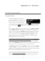
TRANSMITTING AND RECEIVING DATA .......................................................................................................................................................141
Setting Up the Serial Port ..........................................................................................................................................................................141
Dumping Data and Receiving Data Dumps...............................................................................................................................................142
Controlling One H8000FW from Another H8000FW ........................................................................................ 143
Sending A Program From One the H8000FW to Another.................................................................................... 144
Sequencing With MIDI.............................................................................................................................................................................145
CONNECTING USER-SUPPLIED CRYSTALS AND EXTERNAL CLOCKS ..........................................................................................................147
SERVICE AND START-UP OPTIONS ................................................................................................................................................................148
Fixing Internal Memory Problems .......................................................................................................................... 148
Fixing PCMCIA SRAM Memory Card Problems...................................................................................................................................150
Changing the Internal Battery.....................................................................................................................................................................151
Clear Setup................................................................................................................................................................................................152
Software Version and Accessories...............................................................................................................................................................153
Start-Up Options ......................................................................................................................................................................................154
CONNECTING AES 11 THRU 18 TO THE H8000FW....................................................................................................................................156
APPENDIX B-USING THE H8000FW WITH A COMPUTER ___________________________________________ 157
MAKING CONNECTIONS BETWEEN THE H8000FW AND THE COMPUTER. .............................................................................................158
SETTING THE SAMPLE RATE AND BUFFER SIZE FOR THE SYSTEM .............................................................................................................158
SYNCHRONIZING CONNECTED AUDIO DEVICES .........................................................................................................................................159
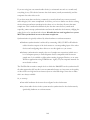
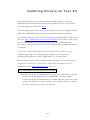
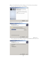
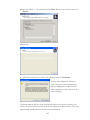
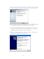
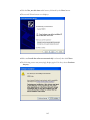
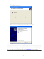
INSTALLING DRIVERS ON YOUR PC _____________________________________________________________ 161
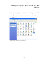
CONFIGURING THE H8000FW FOR PC OUTPUT ___________________________________________________ 167
CONFIGURING THE H8000FW FOR THROUGHPUT ....................................................................................................................................168
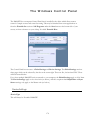
THE WINDOWS CONTROL PANEL _______________________________________________________________ 170
DEVICE SETTINGS ...........................................................................................................................................................................................170
Device Type____________________________________________________________________________________ 170
Device nickname ________________________________________________________________________________ 171
Status 171
Measured Sampling Rate ___________________________________________________________________________ 171
Receiver Status__________________________________________________________________________________ 171
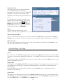
GLOBAL SETTINGS - BUS PAGE .....................................................................................................................................................................171
Master 171
Sample Rate ___________________________________________________________________________________ 171
Sync Source ____________________________________________________________________________________ 171
Buffer Size ____________________________________________________________________________________ 172
Unique ID ____________________________________________________________________________________ 172
PAL, Driver version _____________________________________________________________________________ 172
GLOBAL SETTINGS - ADVANCED PAGE .......................................................................................................................................................172
WDM Enabled_________________________________________________________________________________ 172
Sample Rate Change Restriction ______________________________________________________________________ 172
Operation Mode_________________________________________________________________________________ 172
In/Out Speaker Configuration _______________________________________________________________________ 172
Set WDM Channel Maps__________________________________________________________________________ 173
GLOBAL SETTINGS - DPC PAGE....................................................................................................................................................................174
TROUBLESHOOTING WINDOWS SYSTEMS _______________________________________________________ 175
INSTALLING DRIVERS ON YOUR MACINTOSH ___________________________________________________ 177
CONFIGURING THE H8000FW FOR MACINTOSH OUTPUT _______________________________________ 180
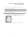
VIEWING THE H8000FW’S CONFIGURATION .............................................................................................................................................180
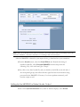
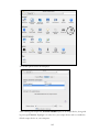
SETTING UP THE H8000FW FOR DEFAULT AUDIO OUTPUT ...................................................................................................................181
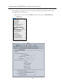
CONFIGURING THE H8000FW FOR OUTPUT WITH LOGIC PRO ...............................................................................................................183
ROUTING AUDIO BETWEEN LOGIC PRO AND THE H8000FW ______________________________________ 185
CREATING AN AGGREGATE AUDIO DEVICE...............................................................................................................................................185
ROUTING AUDIO TO THE H8000FW ...........................................................................................................................................................187
CONFIGURING LOGIC PRO FOR H8000FW INPUT AND OUTPUT.............................................................................................................188
AN EXAMPLE OF USING LOGIC PRO WITH THE H8000FW.......................................................................................................................189
Step-by-Step Descriptions of the Routing Process Flow ________________________________________________________ 191
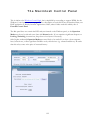
THE MACINTOSH CONTROL PANEL_____________________________________________________________ 192
TROUBLESHOOTING MAC SYSTEMS _____________________________________________________________ 193
ELECTRICAL SPECIFICATIONS __________________________________________________________________ 194
WARRANTY INFORMATION _____________________________________________________________________ 196
INDEX _________________________________________________________________________________________ 199
IMPORTANT SAFETY INFORMATION
• Before powering up the unit, check that the voltage selector on the back panel is set
correctly.
• Do not remove any covers or panels from the unit when the power is connected.
• No operator access to the internals of the unit is permitted - servicing must be
performed by qualified personnel only.
• The unit must not be operated with a damaged or ungrounded power cord.
• Suitable ventilation must be provided for the unit at all times. In particular, the rear
and side vents must not be obstructed. It is best if there is an inch or more
clearance between the top of the H8000FW and the bottom of the units above
and below.
How to Use This Manual
This manual applies to the Eventide H8000FW. For convenience, this and other members
of the H8000FW family may be referred to as H8000FW except where the H8000 differs
from the H8000FW. Most of the information in this manual also applies to H8000 and
H8000A when running software version 5.2 or later.
The first and second chapters of this manual are the most important ones. The first is the
Overview and Quickstart section. In it you will find essential information regarding the
front panel, the back panel, and the general structure of the H8000FW. After these
preliminaries are out of the way, you’ll start using the H8000FW and learning the basic
methodologies that you will employ whenever you use the H8000FW.
The Overview and Quickstart section is not meant to be complete. It’s meant to get
you up and running fast, circumventing thornier issues in favor of speed. If you would
like to know more about a particular topic discussed in this chapter, look to the abundant
references contained therein. They’ll point you to "chunkier" discussions in the remainder
of the manual.
Ideally, we would have you read through the Overview and Quickstart section with the
H8000FW in front of you, following the examples. After you finish the Quickstart
section, we’d have you play with the H8000FW for a while. Once the initial "new box
euphoria" wears off a bit, we’d have you sit down and read the Operation section. A true
appreciation and mastery of the H8000FW cannot be obtained without reading the
manual! We’d have you consult the appendices only when you need specific, technical
information. Finally, when you need to find information days, weeks, months, and years
down the road, we’d have you use the comprehensive Table of Contents and Index.
In particular, a good understanding of The Comprehensive Input / Output Scheme on page 51
and Program Load, Save, Delete, Etc. on page 117 and beyond are necessary to get the best
from the H8000FW. In order to use MIDI Program Change messages it is necessary to
understand Loading a Program Via a MIDI Program Change Message as described on page 120.
For information about using the H8000FW with a PC or Mac see Using the H8000FW
with a computer.
2
O
O vv ee rr vv ii ee w
w aa nn dd Q
Q uu ii cc kk ss tt aa rr tt
The Big Picture
The Eventide H8000FW is a programmable, multi-channel, multipurpose, 96kHz-capable,
dual or monolithic digital signal processor (DSP), 24 bit digital audio signal processor with
UltraShifter™ capability. That’s a lot of adjectives! It is the successor to a long, proud
line of digital signal processors that stretches back to a time when most audio
manufacturers didn’t know digital audio from Morse code.
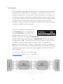
The H8000FW is loaded with features that put it in a class by itself. It has 12 AES/EBU
digital inputs and outputs, eight ADAT digital inputs and outputs, two S/P DIF digital
inputs and outputs, and four analog inputs and outputs, as well as 16 channels or FireWire
for connection to a PC or Mac and very comprehensive routing capabilities for
controlling them. The H8000FW houses two independent signal processors, each having
eight inputs and eight outputs (imaginatively dubbed "DSP A" and "DSP B"). The two
processors can be run in parallel, in series, or in any mutant variation thereof. In addition,
the H8000FW can run "monolithic programs" that use the processing resources of both
DSP A and B to run just one large program.
The variety and depth of the programs that the H8000FW possesses are truly amazing,
from lush reverbs, to choruses, to flanges, to delays, to pitch shifters, to dynamics, to
EQs, to filters, to distortions, to synthesizers, to samplers, to ring modulators, and
everything in-between. The H8000FW can do it all. And if that’s not enough, DSP A
boasts nearly three minutes of sample time in addition to the 44 seconds of delay time
found on both DSP A and DSP B!
And for the user who is interested in making his or her own programs (if the huge number
of factory programs aren’t enough!), the H8000FW continues the "modular programming
paradigm" that made the DSP4000 and its offspring famous. Programs are composed of
individual building blocks, or "modules," that allow the user to create original programs.
Inspiration and creativity are given no bounds. . .
As you read this manual, it may be easy to "lose sight of the forest for the trees." Always
bear in mind the following:
3
• The H8000FW houses two independently running DSPs (digital signal processors).
They are lovingly referred to as "DSP A" and "DSP B." Although they are both
always running, you can only view the parameters for one DSP at a time. Use the
PROCESSOR A/B key to toggle the display between the two DSPs. (Both DSPs
can be combined to run a single, "monolithic" program - see below.)
• Each DSP runs "programs" that are stored in the system. "Programs" are the
algorithms that manipulate your audio. With the exception of "large sampler
programs" and some "long delay" programs, any program can be run on either
DSP. Like two separate effects boxes, the parameters for the program running on
DSP A are totally independent of the parameters for the program running on DSP
B. Like two separate effects boxes, you can connect the outputs of one DSP to
the inputs of the other, or use them completely independently.
• Some processing-intensive programs are designed to run on the resources of both
DSPs. These "monolithic" programs use the input/output routing of DSP A.
While a monolithic program is running, all parameters for DSP B disappear.
• DSP A and DSP B each have eight "virtual" inputs and outputs, which can be
patched to the eight main inputs, each other, or any of their outputs.
See the inserted routing guide for complete routing details.
Never lose sight of the above facts!!! They are the foundation upon which we will build our understanding!!!
4
Knobs, Keys, and Jacks
If this is your first time learning the H8000FW, don’t be put off by some of the rather indepth descriptions that will follow; they exist for your future reference (once you
understand the H8000FW and need a quick bit of information). For now, concentrate on
the names of the various knobs and jacks. Their use will be explained progressively
throughout the rest of this manual.
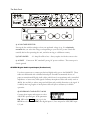
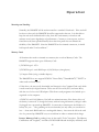
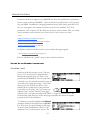
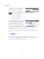
The Front Panel
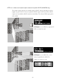
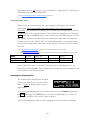
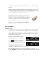
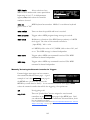
A) Level Meters
These measure the eight signals selected for input, DSP A's eight
inputs, DSP B's eight inputs, DSP A's eight outputs, DSP B's eight outputs, or the eight
main outputs.
→ See The Level Meters on page 74.
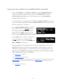
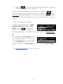
B) System sampling rate and external sync indicator
The top four LEDs display the system sampling rate of the H8000FW: 96kHz, 88.2kHz,
48kHz, or 44.1kHz. When solidly lit, they indicate that the system sampling rate is exact
(+/- 0.05%). When blinking, they indicate that the system sampling rate is between one of
the fixed rates (the LED corresponding to the nearest sampling rate blinks). The bottom LED, EXT,
reflects the current external sync status.
→ See Understanding the "System Sampling Rate and External Sync Indicator" When Using the Internal
Clock on page 85.
→ See Understanding the "System Sampling Rate and External Sync Indicator" When Using the External Clock
on page 89.
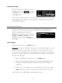
C) BYPASS Press this key to bypass or mute the H8000FW. This key behaves differently
depending on the settings made on the bypass menu page in the LEVELS area.
→ See Bypassing and Muting on page 92.
5
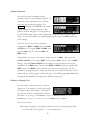
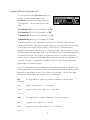
D) Bypass Status LEDs
A illuminated = DSP A is bypassed
B illuminated = DSP B is bypassed
both A and B blinking = system is bypassed
→ See Bypassing and Muting on page 92.
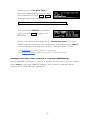
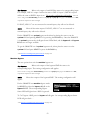
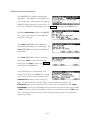
These four keys select the menus or events described immediately
E) SOFT KEYS
above them on the bottom line of the display.
→ See Understanding the Display and SOFT KEYS on page 16.
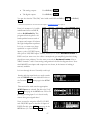
F) THE DISPLAY The display tells you what’s going on. In the upper left-hand corner
of the display is either the letter "A" or "B" or nothing at all. "A" indicates that what is
shown on the display reflects the status of DSP A. Similarly, "B" indicates that what is
shown on the display reflects the status of DSP B. When neither letter is shown, the
H8000FW is running a "monolithic program" that uses the processing resources of DSP
A and DSP B. (Note: the menu pages in the BYPASS, LEVELS, and SETUP areas have
some displays that are common to both DSPs. In these areas, the "A" or "B" is irrelevant.
However, in the PROGRAM, PARAMETER, and Patch Editor areas, menu pages are
DSP specific.) The remainder of the top line displays the name of the program running
on the currently displayed DSP and the current display area you’re working in. The
bottom line is dedicated to the four SOFT KEYS directly below the display. The middle
section of the display changes depending on what you’re doing!
→ See Understanding the Display and SOFT KEYS on page 16.
G) PROCESSOR A/B
Press this key to toggle the display between the status of DSP
A and DSP B. The upper left-hand corner of the display changes when you press this
key; the "A" toggles to "B" and vice versa. Both DSPs are always running, but the display
only shows the parameters pertaining to one of them at a time. If you're running a
"monolithic program," this button does nothing.
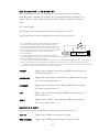
H) PROGRAM/ROUTING Press this key briefly to access program functions such as
loading, saving, deleting, etc. The DSP you are loading into or saving from is referred to
in the left-hand corner of the display ("A" or "B"). To load into or save from the other
DSP, press the PROCESSOR A/B key. If you load a "monolithic program" (indicated by a
roman numeral "II" next to its name), it will effectively load into DSP A, and DSP B will
disappear. If you load a "normal" program next, it will load into DSP A, and the "Thru'"
program will be loaded on DSP B.
→ See Program Load, Save, Delete, Etc. on page 117.
6
Press and hold this key for one second to access the Routing Storage area where "routing
configurations" are loaded and saved.
→ See Signal Flow Example on page 66.
Press and hold this key again for one more second to access the Setup Storage area where
"setup configurations" are loaded and saved.
→ See Storing and Loading Setups on page 139.
Press and hold this key again for one more second to access the Usergroup Storage area
where "usergroup" files may be renamed or deleted.
→See Using User Groups to Organize Useful Programs on page 45.
→See Miscellaneous Setup Options on page 140 to change the "one second hold time" required to enter
the above areas.
I) PARAMETER/PATCH EDIT
Press this key briefly to access parameters for the
programs that are running. The parameters shown are for the program running on the
DSP referred to in the left-hand corner of the display ("A," "B," or nothing at all for
monolithic programs). To see the parameters for the program running on the other DSP,
press the PROCESSOR A/B key.
Press and hold the PARAMETER key for one second to access the Patch Editor. The
patch shown is for the program running on the DSP referred to in the left-hand corner of
the display ("A," "B," or nothing).
→ See the separate Programmer’s Manual for Patch Editor information.
→ See Miscellaneous Setup Options on page 140 to change the "one second hold time".
J) SELECT Press this key briefly to select something highlighted by the cursor or to load
a program on the PROGRAM screen.
Press and hold this key for one second to set up a remote control for whatever parameter
is highlighted on the display.
→ See Remote Controlling Parameters on page 113.
→ See Miscellaneous Setup Options on page 140 to change the "one second hold time".
K) CURSOR KEYS Press these keys to move the cursor on the display. The RIGHT
CURSOR key moves the cursor right, the LEFT CURSOR key moves the cursor left, the
UP CURSOR key moves the cursor up, and the DOWN CURSOR key moves the cursor
down. (We only break from this convention in the case of loading programs, where the
left and right cursor keys do some more interesting stuff!)
→ See Using the Cursor Keys, the SELECT key, the NUMERIC KEYPAD, and the KNOB on page 19.
7
L) THE KNOB
highlighted.
Spin the KNOB to change the value of whatever parameter is
→ See Using the Cursor Keys, the SELECT key, the NUMERIC KEYPAD, and the KNOB on page 19.
→ To change the "one second hold time," alter the "key hold" parameter on the [misc] menu page in the
SETUP area (you may have to press the SETUP key several times to find it).
M) BUSY LED
If a Memory Card is in place, this LED illuminates when data is being
written to the card. Don’t remove the Memory Card if this LED is lit! If no Memory
Card is in place, this illuminates when data is present at the MIDI In port or at the serial
port. Use the latter feature to troubleshoot communication problems between the
H8000FW and the rest of the world.
N) MEMORY CARD SLOT Insert a Memory Card here to add new programs or to save
your own.
→ See Memory Cards on page 49.
O) MEMORY CARD RELEASE
press it if the BUSY LED is lit!).
Press this key to release the Memory Card (but don’t
P) The NUMERIC KEYPAD
Use the numbers, decimal point, and minus sign to enter numeric values or to enter
numeric text in a text field.
CXL "Cancels" the last entered digit. It’s like the backspace key on a computer.
Use these keys to increment or decrement a parameter’s value. When
entering the name of a program, the × key toggles between capital to lower-case letters
and the Ø key toggles between "insert" and "overwrite" modes.
×/Ø KEYS
ENT (Enter) After you’ve entered a numeric value with the NUMERIC KEYPAD, press ENT
to enter it. In many contexts, ENT behaves just like the SELECT key.
→ See Using the Cursor Keys, the SELECT key, the NUMERIC KEYPAD, and the KNOB on page 19.
Q) POWER Flip this switch to bring the H8000FW to life! When the power is off the
unit is bypassed, i.e., most audio inputs are connected to their corresponding audio
output.
R) LEVELS Pressing this key accesses menus for metering and levels.
→ See Controlling Levels on page 74.
S) SETUP Pressing this key accesses menus for routing, digital configuration, MIDI
configuration, service utilities, data dump utilities, and program advance options.
8
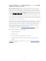
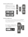
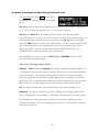
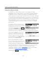
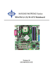
The Back Panel
OPTIONS
a
b
c
WORD CLOCK
l
m
i
MIDI
SP/DIF
h
f
d
e
k
o
n
q
p
j
g
a) AC VOLTAGE SELECTOR
Line up the dot with the triangle so that your preferred voltage is up. It is absolutely
essential that you select the voltage corresponding to your local AC power! Check this
carefully before first powering the unit, and after moving to a different country.
b) FUSE HOLDER
A 1-Amp Slow Blow fuse. Always replace it with the correct value.
c) AC PORT Connect an IEC standard 3-prong AC power cord here. The center post is
chassis ground.
AES/EBU Digital Audio Input/Output (Professional)
Use these connectors to connect professional digital audio gear to the H8000FW. These
cables are differential with a shielded twisted pair. Eventide recommends the use of
purpose-manufactured Digital Audio cables, which have low capacitance and a controlled
impedance to better carry AES signals. Ordinary microphone cables will usually work at
48kHz, but are likely to reduce range and add jitter and possibly distortion to the signal. It
is unlikely that long lengths of microphone cable will prove satisfactory for 96kHz
operation.
d) AES/EBU INPUT AND OUTPUT JACKS
Connect these inputs and outputs to other
AES/EBU-specified gear. If the parameter
DIN 1/2 on the inputs menu page in the
SETUP area is set to AES/EBU, then digital inputs 1/2 are accepted at AES/EBU input
1/2 jack.
9
Note that AES/EBU 1/2 can be used as sync sources on the H8000 and H8000A, but
not on the H8000FW.
→ See Digital Setup on page 80.
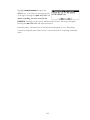
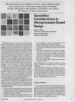
e) ANALOG AUDIO INPUT AND OUTPUT JACKS
The H8000FW’s XLR analog audio output jacks are male. Pin #1 is ground. Pin #2 is
+phase (hot) and pin #3 is -phase.
To "unbalance" the jack, use pins #1 and #3 as ground and use pin #2 as "hot." Be
aware that this will reduce the maximum output level by 6dB, so you
should usually reduce the output gain by 6dB to compensate.
1
2
⇒See
1/4"
Controlling the Level of the Analog and Digital Outputs on page 78.
3
If either pins #2 or #3 are unconnected, you will get more noise
than signal !
1
2
3
The H8000FW’s analog inputs accept either mono or stereo 1/4" connectors or balanced
XLR connectors. The H8000FW’s XLR input connectors are female. Pin #1 is ground.
Pin #2 is +phase (hot) and pin #3 is -phase. These may be connected to an unbalanced
input as described above.
To "unbalance" the XLR or 1/4" jack, use both pins #1 and #3 as ground and use pin
#2 as "hot." If either pins #2 or #3 are unconnected, you will get more noise and
hum than signal !
These may be used as both line and guitar inputs, depending on the input level setting.
Using a "mono" jack will correctly unbalance the input.
→ See Controlling the Level of the Analog and Digital Inputs on page 75.
S/P DIF Digital Audio Input/Output (Consumer)
S/P DIF is a consumer digital audio standard, with two audio channels encoded into a
single connector. Use these connectors to hook up the H8000FW to CD players, DAT
recorders, and other audio gear using this format. The connectors are two-conductor
RCA jacks. Your plug should have the shield connected to the sleeve with the single
shielded conductor connected at the tip.
10
Eventide recommends the use of professional quality cables made of RG-59/U coaxial
cable. Ordinary "hi-fi" type leads will probably prove inadequate. Eventide does not
recommend the use of S/PDIF at sample rates above 48kHz.
f) S/P DIF 1/2 INPUT AND OUTPUT JACKS
To enable the S/P DIF digital input 1/2, set DIN 1/2
on the inputs menu page in the SETUP area to S/P
DIF. This will disable AES1/2.
Note that these connectors can be used as sync sources on the H8000 and H8000A, but
not on the H8000FW.
→ See Digital Setup on page 80.
g) S/P DIF 3/4 INPUT AND OUTPUT JACKS
To enable the S/P DIF digital input 3/4, set DIN
11/12 on the inputs menu page in the SETUP area to
S/P DIF. This will disable AES11/12. The input
circuitry for S/P DIF 3/4 allows better performance than S/P DIF 1/2 and will operate
better at 96kHz or with long leads.
h) FOOT PEDAL JACKS 1 AND 2
Stereo 1/4" connectors. The sleeve is ground reference, the ring is +5 volts (source), and
the tip is an analog signal from 0 to 5 volts. Connect either foot switches, foot pedals, or
control voltage sources to these inputs to modulate parameters or to trigger events
(including remote program loads).
→ See Foot Pedals 1 and 2 on page 94.
i) RELAY JACK
Two relays are connected to this stereo 1/4" connector. They can be controlled from
suitable programs, allowing the H8000FW to drive real-world equipment, and can switch
up to 1A at 30V dc. Relay #1 is connected between ring and sleeve, while Relay # 2 is
connected between ring and tip. All of these connections are electrically isolated from the
H8000FW. See the separate Programming Manual for information on controlling the
relays.
j) OPTICAL INPUT AND OUTPUT JACK
These send and receive digital audio to and from other ADAT-capable devices, using a
standard "light-pipe" connector. They also support SMUX operation, carrying four
channels at 88.2 or 96kHz. To use signals from the ADAT input, select them at the
11
inputs menu page in the SETUP area. To route signals to the ADAT output, select them
at the outputs menu page in the SETUP area.
These jacks may also be used as optical-type S/P
DIF connectors. The optical input may be
assigned to one pair of AES11/18, which will
disable that pair as AES inputs. If AES11/12 is
selected as an optical input it cannot also be selected as an electrical S/P DIF input so the
DIN11/12 control is disabled.
The optical output may be fed from any one pair
from AES11/18. Clearly, if either of these
connectors is used for S/P DIF the
corresponding ADAT signals will be disabled.
k) MIDI
MIDI is used for instrument-to-instrument digital communications. The H8000FW sends
and receives Eventide system exclusive messages that allow a MIDI sequencer or foot pedal
(among other things) to remote control the H8000FW. In addition, the H8000FW may
respond to standard MIDI messages and may output standard MIDI messages. The
H8000FW has three MIDI ports:
- the H8000FW accepts (and processes) MIDI messages received at the MIDI In
port. The connector is "7 pin" and can also send MIDI messages to a suitably equipped
system. A normal "3 pin" MIDI cable can be used as a standard MIDI input.
IN
OUT - the H8000FW sends MIDI messages to other devices via the Out port. MIDI messages
are also sent out the serial port if they are "enabled."
THRU - Any MIDI information received at the MIDI In port is echoed directly to the
MIDI Thru port regardless of the H8000FW’s configuration (as long as the H8000FW is
powered up) .
With the Memory Card removed, the BUSY LED on the front panel illuminates whenever a MIDI message is received at the
MIDI In port. Note: If the serial port is "enabled" and MIDI is "enabled," a command received over either the serial port or
the MIDI In port causes the port not receiving the command to be ignored until the command is complete.
→ See MIDI Setup on page 95.
l) EVE/NET
RJ45 jack for use with Eve/Net remote controllers. See the Eventide Web Site
http://www.eventide.com for more information on Eve/Net. Do not connect this jack
to an Ethernet network or electrical damage may result.
12
m) SERIAL PORT
An IBM PC type RS232 connector that looks like a modem or printer to a connected
computer. Connect a "9 pin" serial cable to this port to transfer information to and from
a personal computer. Do not use the "null modem" type of cable designed for file transfer
between two computers - it will not work.
With the Memory Card removed, the BUSY LED on the front panel illuminates whenever a message is received at the serial
port. Note: If the serial port is "enabled" and MIDI is "enabled," a command received over either the serial port or the
MIDI In port causes the port not receiving the command to be ignored until the command is complete.
→ See Setting Up the Serial Port on page 141.
n) FIREWIRE CONNECTORS
Two identical IEEE-1394 FireWire connectors. Typically one is connected to a PC or
Mac, and the other is available for “daisy-chain” connections to other FireWire devices or
may be left unconnected.
Note: while FireWire is specified as being “hot-swappable”, meaning that connectors may
be plugged and un-plugged with power applied, Eventide recommends that this NOT be
done, and that where possible FireWire connections be only changed when all equipment
is powered down.
o) AES11/18 input and output connector
This DB25 connector carries the input and output signals for AES/EBU signals 11 to 18.
See Connecting AES 11 thru 18 to the H8000FW on page 156.
p) WORD CLOCK INPUT AND OUTPUT JACKS
The H8000FW sends a clock signal from its word clock output which can be used to
synchronize other equipment to the H8000FW. The H8000FW can also slave to another
device’s word clock output.
q) STATUS LEDS
These two LEDs indicate the status of the FireWire subsystem. The top LED should be
lit when a FireWire cable is connected. The lower one should flash from time to time to
show activity, especially when a connected device becomes locked or unlocked. If it
flashes rapidly and continuously, a bad connected device or connection is indicated.
13
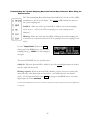
Getting Around and Altering Parameters
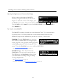
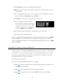
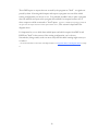
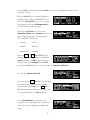
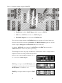
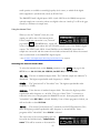
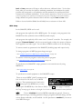
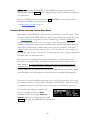
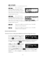
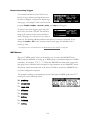
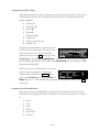
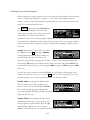
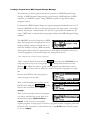
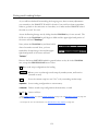
Adjusting the Brightness and Contrast of the Display
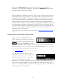
Before we begin to describe the H8000FW’s
interface, we ought to make sure you can see the
display! To adjust the contrast of the display, press
the SETUP key four times, then press the leftmost SOFT KEY under the display menu.
Turn the KNOB to adjust contrast or press the DOWN CURSOR key and turn the KNOB to
adjust brightness.
The "Areas" of the H8000FW
The H8000FW’s interface is divided into several functional "areas." You access each area
by pressing its key. You’ll know which area you’re in because the LED next to its key
illuminates (except for the BYPASS area, but that one’s obvious). The areas are:
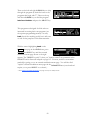
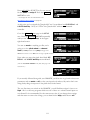
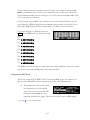
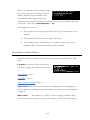
PROGRAM Press the PROGRAM key to access this
area. Inside you’ll find utilities for sorting programs,
loading programs, saving programs, deleting programs,
and grouping programs of your choosing into "user
groups." Press the PROGRAM key to access additional SOFT KEYS.
→ See Program Load, Save, Delete, Etc. on page 117.
ROUTING Storage Press and hold down the
PROGRAM key for one second to access this area.
The LED next to the PROGRAM key blinks. Here
you’ll find utilities for loading, saving, or deleting
"routing configurations."
→ See Signal Flow Example on page 66.
→ To change the "hold time," see Miscellaneous Setup Options on page 140.
14
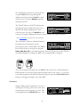
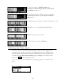
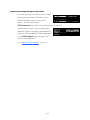
SETUP Storage
Press and hold down the
PROGRAM key again for one second to access this
area. The LED next to the PROGRAM key blinks.
Inside you’ll find utilities for loading, saving, or
deleting "setup configurations."
→ See Storing and Loading Setups on page 139.
→ To change the "hold time," see Miscellaneous Setup Options on page 140.
Press and hold down the PROGRAM key again for one second to
access this area. The LED next to the PROGRAM key blinks. Inside you’ll find utilities
for renaming or deleting "User Groups."
USERGROUPS
→ See Using User Groups to Organize Useful Programs on page 45.
Press the PARAMETER key to
access this area. Here you’ll find the parameters for
the currently loaded programs. Continue pressing the
PARAMETER key to access additional SOFT KEYS (if
available).
PARAMETER
→ See Parameters on page 133.
The PARAMETER key also gives access to the built-in
Patch Editor. Press and hold down the PARAMETER
key for one second to access this area. The LED next
to the PARAMETER key blinks. The Patch Editor
allows you to create your own effects from scratch or to customize programs that already
exist.
→ See the separate Programmer’s Manual for more information on the Patch Editor.
→ To change the "hold time," see Miscellaneous Setup Options on page 140.
Press the LEVELS key to access this area.
Inside you’ll find level and Level Meter parameters.
LEVELS
→ See Controlling Levels on page 74.
Press the SETUP key to access this global,
"catch-all" area. Inside you’ll find routing parameters,
digital setup controls, global MIDI setup, global
"external" setup, display contrast/brightness, the pedal
jacks’ setup, dump data utilities, next/previous program advance, and miscellaneous
service utilities. Press the SETUP key more than once to access additional SOFT KEYS.
SETUP
15
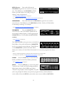
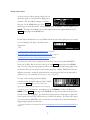
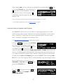
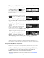
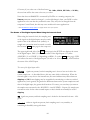
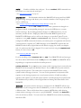
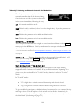
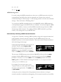
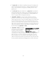
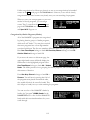
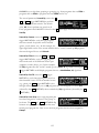
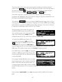
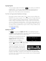
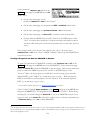
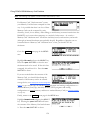
Understanding the Display and SOFT KEYS
Every "area" in the H8000FW makes use of the display, so understanding the display is
critical. A generic screen of the sort typically found in the PARAMETER area is shown
below. It exemplifies various aspects of the display that remain constant no matter what
area of the H8000FW you’re in.
First, in the upper left-hand corner of the screen is either the letter "A," the letter "B," or
the beginning of the program name This is the "DSP Display Indicator." If it reads "A,"
then everything else on a "DSP sensitive" screen is in reference to DSP A. If it reads "B,"
then everything else on a "DSP sensitive" display is in reference to DSP B. Press the
PROCESSOR A/B key to toggle the display between the two DSPs. The screens in the
PROGRAM, PARAMETER, and Patch Editor are "DSP sensitive." Both DSPs are always
running, but the display only shows the parameters for one of them at a time. The "DSP Display
Indicator" lets you know which one you’re modifying. Look to it often.
If there is no "A" or "B" in the upper left-hand corner of the screen, the H8000FW is
running a "monolithic program." Monolithic programs use the signal processing resources
of both DSPs. They use the routings for DSP A. While a monolithic program is loaded,
DSP B effectively disappears.
The remainder of the upper left-hand corner of the screen always shows the name of the
program currently running on the DSP referred to by the "DSP Display Indicator." In
16
the example shown above, we’re running a program "1210 Chorus" on DSP A. The
upper right-hand corner of the screen always describes the menu page you’re looking at.
In the example shown above, we’re looking at the "chorus 2 params" menu page.
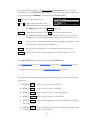
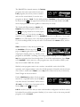
Situated along the bottom of the display are the so-called "SOFT KEYS." The four
physical keys located below the display select menu pages or events corresponding to
these SOFT KEYS. (They’re called "soft" because their function changes depending on
context.) The "More Soft Keys" indicators are the little arrows next to the first and last
SOFT KEYS. They indicate that if you press the "area" key you used to access the current
display again, you will access more SOFT KEYS. The arrows are meant to imply that more
pages exist in a nether-world beyond the display. . .
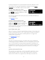
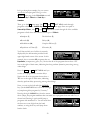
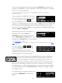
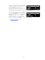
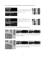
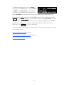
For example, press the SETUP key to see the
"More Soft Keys" indicators.
Press the SETUP key again to get more SOFT
KEYS.
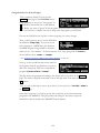
Press the SETUP key a few more times to return to the original set of SOFT KEYS.
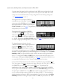
A "Stacked" SOFT KEY (shown on the format and pedals menu pages above) indicates
that if you repeatedly press the "stacked" SOFT KEY, you will access more menus. The
graphic is meant to imply that there are more pages lying "below" the "top" one.
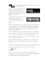
For example, repeatedly press the SETUP key
until you see the stacked SOFT KEY midi . Press
midi .
Press it again to get a second menu page.
17
Press it again to get a third menu page.
Press it twice more to return to the original menu page.
Pressing a SOFT KEY repeatedly that is not stacked puts the H8000FW into "self-destruct"
mode. Just kidding. It has no effect.
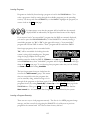
When you press a SOFT KEY, it becomes highlighted. The middle section of the screen is
a menu page corresponding to that highlighted SOFT KEY. Use the cursor keys to "move
around" on the menu page. Use the KNOB, the NUMERIC KEYPAD, and the SELECT key
to change and enter values.
→ See Using the Cursor Keys, the SELECT key, the NUMERIC KEYPAD, and the KNOB on page 19.
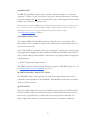
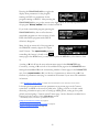
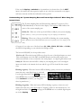
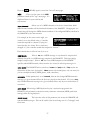
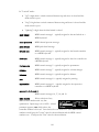
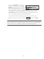
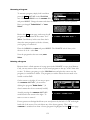
Before moving on, we ought to say that not all SOFT KEYS are menu pages. Some SOFT
KEYS are "triggers." A "trigger" is a key that triggers an event, get it? You’ll always know
the difference between menu page SOFT KEYS
and trigger SOFT KEYS because menu page SOFT
KEYS are rectangular, whereas trigger SOFT KEYS
are hexagonal. On this screen Operate and
info are menu pages, and <On/Off> is a trigger.
18
Using the Cursor Keys, the SELECT key, the NUMERIC KEYPAD, and the KNOB
We use the CURSOR keys, the KNOB, the SELECT key, and the NUMERIC KEYPAD to
navigate and manipulate the menu pages found in the PARAMETER, Patch Editor,
LEVELS, BYPASS, and SETUP areas. We’ll discuss their use in the PROGRAM and
Routing Storage areas in a bit.
Use of the cursor keys is straightforward. The LEFT and RIGHT CURSOR keys move the
cursor left and right, respectively. The UP and DOWN CURSOR keys move the cursor up
and down, respectively. (Go figure...)
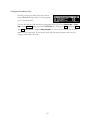
Use the KNOB, NUMERIC KEYPAD, or the ×/Ø
keys to alter the value of a numeric parameter.
For example, spin the KNOB on this screen to
change the value of Mix or enter a new value
directly with the NUMERIC KEYPAD (pressing ENT when you’re done).
Use the KNOB or the ×/Ø keys to alter the value
of a text parameter. For example, spin the
KNOB or press the × key to change Shape from
Sine to Triangle on this screen.
Numeric parameters and text parameters cover 99% of the parameters you’ll see in the
H8000FW, but there are a few more esoteric parameters you’ll encounter. One such
oddball is the "trigger" parameter. You place the cursor over a trigger parameter, and
trigger it by pressing SELECT. It will trigger something (no doubt fascinating) to happen.
Other oddballs include "Taps" and "Graphics."
→ See System Tempo on page 134.
→ See Graphics and Curves on page 137.
→ The left and right cursor keys behave differently than you might expect in the PROGRAM area. Please see
Loading Programs on page 38 for a brief introduction, and Loading Programs on page 125 for a more
detailed discussion.
→ See wheel speed on page 140.
19
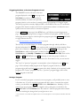
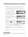
Ganged Parameters
In some cases there are multiple, related
parameters that are usually adjusted together. To
make such "mass adjustments" easy, a feature
exists that gangs parameters together. The
outputs menu page in the SETUP area contains
a good example of ganged parameters. The
purpose of this menu page is to assign signals to
the AES/EBU digital outputs. Such assignments are typically made in quad or stereo
gangs. So, all four parameters are initially ganged together. Spin the KNOB and all four
values change.
Now, let’s say you only want to change the
assignments to DIG1 and DIG2. Press the DOWN
CURSOR key to "un-gang" DIG3 and DIG4. Now
spin the KNOB; only the values for DIG1 and
DIG2 change.
Going further, let’s say you only want to change the value of DIG1. Again, press the
DOWN CURSOR key to "un-gang" DIG2. Now, spin the KNOB - only the value of DIG1
changes. Press the DOWN CURSOR key repeatedly to cycle through the various gang
possibilities: next DIG2 alone is selected, then DIG3 and DIG4 are ganged together, then
DIG3 is alone, then DIG4 is alone, and lastly we arrive at our starting point - all four
parameters are ganged together. Gangs are much easier to use than to describe, so take a
minute and play with the gangs on this menu page. You will find gangs sprinkled liberally
throughout the H8000FW as their presence facilitates many tasks.
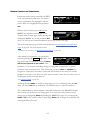
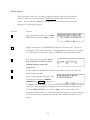
Entering or Changing Text
In some menus, it will be necessary to enter or
change text. For example, you will often change
text when saving a new program. The method
by which this is done is straightforward, albeit a
bit tedious. To play along, go to the PROGRAM area and press the <Save as> SOFT KEY. (You may have to press the
PROGRAM
key a second time to see it.) Move the cursor over the rename field and press SELECT.
Here’s how it works:
• The upper-left portion of the display contains the text that’s being changed. Here
we’ve entered "I Can Type Fas..." - we’re not quite done.
20
• The CURSOR keys take you around the virtual keyboard.
• SELECT enters the currently selected letter (equivalent to actually pressing a key on a
real keyboard).
• The Ø key toggles between "insert" and "overwrite" modes. Alternatively, you can
place the cursor over Ovr/Ins and press SELECT.
• The KNOB moves the insert/overwrite point on the top row.
• The × key toggles between capital and
lower-case letters and gives you access to
very special characters such as "!", "@",
and "&". Alternatively, you can place the
cursor over Caps and press SELECT.
• The numeric keypad enters numbers, a decimal point, or a minus sign.
• CXL will delete the current character.
When you are finished naming the thing that needed naming, place the cursor over Enter
and press SELECT (or use the ENT key on the keypad). If you change your mind and
don’t want to name the thing that you thought needed naming, place the cursor over Quit
and press SELECT.
QuickStart Or "Nearly Instant Gratification"
All right, all right! Areas, displays, SOFT KEYS, parameter this, scroll that. . . BUT WHAT
CAN IT DO? Let’s cut to the chase and get you up and running! Besides, if you played
with the box a good deal before moving on to the finer points of operation, those finer
points will stick better to the ol’ gray matter. . .
Here are the steps we will take:
First, we’ll connect the H8000FW to the rest of your gear.
• On page 25, we’ll route signals between all of those inputs, outputs, and DSPs you’ve
been reading so much about.
• On page 37, we’ll set the input levels so that things don’t distort.
• On page 38, we’ll learn how to "mute" the H8000FW in the event of feedback.
21
• On page 41, we’ll run programs on DSP A and DSP B and we’ll run "monolithic
programs." Moreover, we’ll "tweak" their parameters.
• Finally, on page 44, we’ll learn how to save the programs you’ve "tweaked" for future
use.
HOOKING UP AND INTERNAL ROUTING
Before we concentrate on what happens inside the H8000FW, we ought to get it hooked
up to the rest of your rack.
→ See The Back Panel on page 9 for information on the jack types and their specifications.
Hook up the analog inputs to suitable output
sources, such as an analog mixer’s effect sends
or the outputs of a preamplifier. The
connections may be made with either balanced
XLR connectors or unbalanced 1/4" connectors. You can plug a guitar into the 1/4"
jacks, but you will need to turn up the input gain. This happens at the "bottom" inputs
menu page in the LEVELS area.
→ See Setting Input Levels on page 37.
• Hook up the balanced analog outputs to suitable input recipients, such as an analog
mixer or an amplifier.
• Hook up the AES/EBU, S/P DIF, and/or ADAT digital inputs to suitable output
sources, such as a computer interface or a keyboard with digital outputs.
• Hook up the digital outputs to suitable input recipients, such as a computer interface
or a sampler.
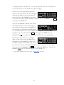
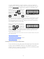
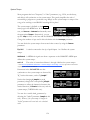
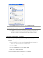
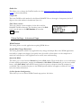
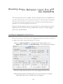
You can specify whether the S/P DIF and
AES/EBU 1/2 output signal uses the
"consumer" or "professional" protocol at the
"second" format menu page in the SETUP area. To select the "consumer" protocol set
DOUT 1/2 to S/P DIF. To select the "professional" protocol set DOUT 1/2 to AES/EBU.
(H8000 display shown; H8000FW is slightly different.)
To be clear, the signal assigned to digital outputs 1/2 will come out both the AES/EBU
1/2 port and the S/P DIF port regardless of your choice. Your choice simply defines the
digital protocol the signal will use. Both AES/EBU 1/2 and S/P DIF use the same protocol
as defined on this menu page. Use the professional (AES/EBU) protocol unless you have
22
a compelling reason to do otherwise ... you are a professional, aren't you ? Eventide does
not recommend the use of S/P DIF above 48kHz sampling.
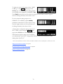
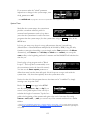
Unless you’re only using the analog inputs and
outputs, you’ll need to make sure all of the digital
devices in your studio or rack are slaved to the
same clock source. The H8000FW can generate
its own clock at 44.1kHz, 48kHz, 88.2kHz, or 96kHz as selected by Source on the clock
menu page in the SETUP area.
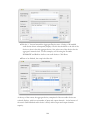
If you use the H8000FW’s internal clock, be sure
that the digital devices that are connected to it
derive their clock signals from the H8000FW. If
you are unable to synchronize AES/EBU inputs
1-4 or S/P DIF inputs 1/2, turn on the H8000FW’s sample rate conversion (SRC)
algorithm on the "second" and "third" clock menu pages in the SETUP area. The
H8000FW does not have sample rate conversion for AES11-18 or the ADAT inputs.
Depending on the particulars of your digital
setup, you may wish to slave the H8000FW to
another device. The H8000FW can slave to the
S/P DIF 3/4 input, the AES/EBU inputs 11/12,
13/14, 15/16, 17/18, or the ADAT and FireWire inputs as well as a Wordclock signal.
These are selected by Source on the clock menu page in the SETUP area. Note that the
H8000FW cannot slave to AES/EBU inputs 1-4 or S/P DIF 1/2.
→ To read about the digital setup in more detail, see Digital Setup on page 80.
23
Things to Know about Routing
When you are ready, see The Comprehensive Input / Output Scheme for more details. Until then …
• The effects engine (the DSP section) of the H8000FW has eight inputs and outputs
• Only 8 inputs can be connected to the effects engine
• Only 8 outputs can be connected from the effects engine
• The analog inputs can only be used as input channels 1-4 (7-8 on H8000)
• The analog outputs are always connected as output channels 1-4 (7-8 on H8000)
• The AES XLR inputs can only be used as input channels 5-8 (1-8 on H8000)
• The AES XLR outputs are always connected as output channels 5-8 (1-8 on H8000)
• S/P DIF 1/2 in can replace AES 1/2 in
• S/P DIF 1/2 out is driven with the same signal as AES 1/2 out
• ADAT out can be fed from the effects engine or from the ADAT inputs
• In addition, for the H8000FW
• S/P DIF 3/4 in can replace AES 11/12 in
• S/P DIF 3/4 out is driven with the same signal as AES 11/12 out
• ADAT1-8 out can be fed from the effects engine or from the ADAT, AES11-18 or
FireWire inputs
• AES11-18 out can be fed from the effects engine or from the ADAT, AES11-18 or
FireWire inputs
• FireWire outputs can be fed from the effects engine or from the ADAT or AES1118 inputs
• FireWire outputs can not be fed directly from FireWire inputs
24
LOADING ROUTING CONFIGURATIONS
As was stated in the Overview, the H8000FW houses two separate DSP engines. DSP A is
always running a program and DSP B is always running another program or they "combine
their forces" to run one large program (monolithic mode). When using both processors
separately, the program running on DSP A does not necessarily have anything to do with the
program running on DSP B, and the program running on DSP B does not necessarily have
anything to do with the program running on DSP A! (The display can only show the
parameters for one of them at a time - use the PROCESSOR A/B key to toggle between
displays.)
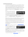
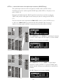
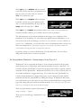
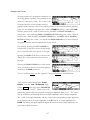
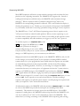
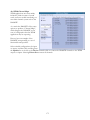
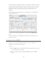
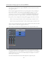
When running "monolithic" programs, DSP B
effectively disappears. The monolithic program
uses the routing configuration for DSP A. When
you are done with the monolithic program and
load DSP-specific program, DSP B’s previous routings will be restored - it will "reappear."
You can identify monolithic programs in the PROGRAM area by a Roman Numeral "II" next
to their name (e.g., DynoMyPiano_Ambience and Piano & Vocal Halls in this screen
shot).
While the functioning of DSP A is quite independent of DSP B and vice versa, we can route
signals between them. Each DSP can accept eight input signals and produce eight output
signals. The signal routing between the various ins and outs and the two DSPs is
comprehensive and can be manually configured in just about any way imaginable. However,
for the purposes of this "Instant Gratification" section, we’ll stick to a sample of the routing
configurations that come as presets in the H8000FW. (Besides, you’ll probably use these
preset configurations most of the time because they cover the most obvious and necessary
routing configurations.)
→ To learn how to manually configure the routing configuration, see The Comprehensive Input / Output
Scheme on page 51.
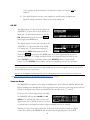
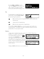
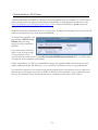
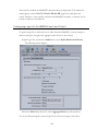
To access the preset routing configurations, press
and hold down the PROGRAM key for one second
to enter the Routing Storage area. The LED next
to the PROGRAM key will begin to blink and the
upper right-hand corner of the display will read "Routings." Use the UP and DOWN
CURSOR keys to place the cursor over the routing configuration you would like to load and
then press SELECT. Below, we describe many of the preset routing configurations in English
and complement that description with a block diagram. The routing configuration "name" as
saved in the H8000FW precedes each description.
→ To change the "one second hold time," see Miscellaneous Setup Options on page 140.
25
For a simple Analog in Analog out routing, load “Analog A->B.” The remainder of the
routing configurations will be discussed in the next section.
26
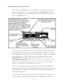
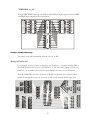
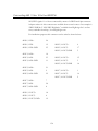
FACTORY ROUTING CONFIGURATIONS
Notes on the following configurations:
• The input block and output block shown below are just “binding posts” to connect to –
they don’t change the signal.
• References to AES11-18, SPDIF3/4 and FIREWIRE in the following text only
apply to the H8000FW.
• In most of the following routings ADAT out, AES11-18 out and FIREWIRE1 out
are also all connected in parallel to the output block – the outputs shown in the
diagram vary with the function of the routing, but all the above are connected.
• FIREWIRE2 in and out are not used in most of these routings.
• SPDIF1/2 in may be used in place of AES1/2 by setting the DIN 1/2 control
appropriately.
See DIN 1/2 allows the selection of either AES/EBU or S/P DIF on page 63.
• SPDIF3/4 in may be used in place of AES11/12 by setting the DIN 11/12 control
appropriately. You should use SPDIF3/4 rather than SPDIF 1/2 if you want to
sync to it or use it at 96kHz.
See DIN 11/12 allows the choice of either AES/EBU or S/P DIF for AES11/12. (H8000FW only) on pag 63.
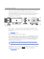
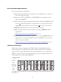
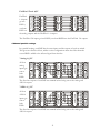
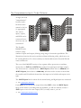
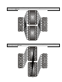
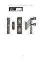
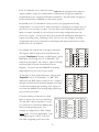
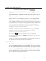
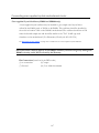
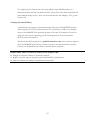
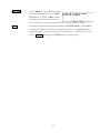
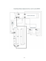
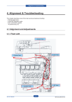
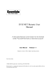
4 Channel series Routings
With a series routing, the signal goes into DSP A and has an effect added, then the
effected signal goes to machine B, where another effect is added, both to the original
signal and also the effect from DSP A. This is useful if DSP A is, say, a coloration and
DSP B is a reverb, but may be less appropriate if they are, say, both pitch shifters as the
shifted signal from A will be shifted again by B.
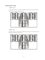
"Analog A->B"
27
analog
outputs
AES1-4
outputs
output block
DSP B
DSP A
input block
AES1-4
inputs
analog
inputs
All four
1
1
1
1
1
1
1
1
1
1
2
2
2
2
2
2
2
2
2
2
analog
3
3
3
3
3
3
3
3
3
3
inputs go
4
4
4
4
4
4
4
4
4
4
1
5
5
5
5
5
5
5
5
1
into DSP
2
6
6
6
6
6
6
6
6
2
A, the
3
7
7
7
7
7
7
7
7
3
4
8
8
8
8
8
8
8
8
4
output
from DSP A goes into DSP B, the output from DSP B goes into both the analog outputs
and AES 1-4.
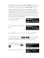
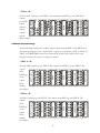
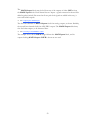
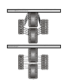
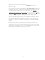
"AES4 A->B"
analog
outputs
AES1-4
outputs
output block
DSP B
DSP A
input block
AES1-4
inputs
analog
inputs
All four AES1-4 inputs go into DSP A. The outputs from DSP A go into DSP B, the
outputs
1
1
1
1
1
1
1
1
1
1
from DSP
2
2
2
2
2
2
2
2
2
2
B feed
3
3
3
3
3
3
3
3
3
3
4
4
4
4
4
4
4
4
4
4
both the
1
5
5
5
5
5
5
5
5
1
analog
2
6
6
6
6
6
6
6
6
2
3
7
7
7
7
7
7
7
7
3
outputs
4
8
8
8
8
8
8
8
8
4
and the
digital outputs.
8 Channel series Routings
All the following routings take 8 inputs and pass them through DSP A, then DSP B and
then feed the outputs via the “output block.” Again, all of the analog, AES1-4, AES11-18,
ADAT and FIREWIRE1 outputs are connected in parallel to the output block, even
though for clarity only one set of outputs is shown.
output block
DSP B
DSP A
input block
ADAT inputs
All eight ADAT inputs go into DSP A. The outputs from DSP A go into DSP B. The
outputs
1
1
1
1
1
1
1
1
1
1
from
2
2
2
2
2
2
2
2
2
2
3
3
3
3
3
3
3
3
3
3
DSP B go
4
4
4
4
4
4
4
4
4
4
to the
5
5
5
5
5
5
5
5
5
5
6
6
6
6
6
6
6
6
6
6
output
7
7
7
7
7
7
7
7
7
7
block,
8
8
8
8
8
8
8
8
8
8
feeding
the outputs.
ADAT outputs
"ADAT A->B"
28
output block
DSP B
DSP A
input block
AES11-18 inputs
All AES11-18 inputs go into DSP A. The outputs from DSP A go into DSP B. The
outputs
1
1
1
1
1
1
1
1
1
1
from
2
2
2
2
2
2
2
2
2
2
3
3
3
3
3
3
3
3
3
3
DSP B go
4
4
4
4
4
4
4
4
4
4
to the
5
5
5
5
5
5
5
5
5
5
6
6
6
6
6
6
6
6
6
6
output
7
7
7
7
7
7
7
7
7
7
block,
8
8
8
8
8
8
8
8
8
8
feeding
the outputs.
AES11-18 outputs
"AES8 A->B"
"FireWire1 A->B"
1
2
3
4
5
6
7
8
1
2
3
4
5
6
7
8
1
2
3
4
5
6
7
8
1
2
3
4
5
6
7
8
1
2
3
4
5
6
7
8
1
2
3
4
5
6
7
8
FireWire1 outputs
1
2
3
4
5
6
7
8
output block
1
2
3
4
5
6
7
8
DSP B
1
2
3
4
5
6
7
8
DSP A
1
2
3
4
5
6
7
8
input block
FireWire1 inputs
All FireWire1 inputs go into DSP A. The outputs from DSP A go into DSP B. The
outputs from DSP B go to the output block, feeding the outputs.
Stereo Dual Machine Routings
The following routings configure the H8000FW as two separate stereo units.
1
2
3
4
5
6
7
8
1
2
3
4
5
6
7
8
1
2
3
4
1
2
3
4
analog
outputs
1
2
3
4
1
2
3
4
AES1-4
outputs
1
2
3
4
1
2
3
4
output block
1
2
3
4
5
6
7
8
DSP A
1
2
3
4
5
6
7
8
DSP B
1
2
3
4
1
2
3
4
input block
AES1-4
inputs
analog
inputs
“Analog Dual Stereo”
Analog inputs 1&2 are sent to DSP A, the output of which is sent to the first two analog
and digital outputs. Analog inputs 3&4 are sent to DSP B, the output of which is sent to
analog and digital outputs 3&4.
1
2
3
4
5
6
7
8
1
2
3
4
5
6
7
8
1
2
3
4
1
2
3
4
analog
outputs
1
2
3
4
1
2
3
4
AES1-4
outputs
1
2
3
4
1
2
3
4
output block
1
2
3
4
5
6
7
8
DSP A
1
2
3
4
5
6
7
8
DSP B
1
2
3
4
1
2
3
4
input block
AES1-4
inputs
analog
inputs
“AES4 Dual Stereo”
AES/EBU inputs 1&2 are sent to DSP A, the output of which is sent to the first two
analog and digital outputs. AES/EBU inputs 3&4 are sent to DSP B, the output of which
is sent to analog and digital outputs 3&4.
29
4 channel Dual Machine Routings
The following routings configure the H8000FW as two separate 4 channel units. If a dual
stereo preset, e.g. “1030 2 Stereo Verbs” is loaded in each DSP, this will give 4
independent effects.
1
2
3
4
5
6
7
8
1
2
3
4
5
6
7
8
1
2
3
4
1
2
3
4
analog
outputs
1
2
3
4
1
2
3
4
AES1-4
outputs
DSP A
DSP B
AES1-4
inputs
input block
analog
inputs
1
1
1
1
The four
2
2
2
2
analog
3
3
3
3
4
4
4
4
inputs
1
1
5
5
and
2
2
6
6
3
3
7
7
outputs
4
4
8
8
use DSP
A. The four AES1-4 inputs and outputs use DSP B.
output block
"Analog&AES 8 Track A,B"
"ADAT 8 Track A,B"
DSP B
input block
ADAT inputs
The last
four
ADAT
inputs go
into DSP
B, out from DSP B into the last four ADAT outputs.
1
2
3
4
1
2
3
4
1
2
3
4
5
6
7
8
1
2
3
4
1
2
3
4
1
2
3
4
5
6
7
8
1
2
3
4
5
6
7
8
1
2
3
4
5
6
7
8
ADAT outputs
1
2
3
4
1
2
3
4
1
2
3
4
5
6
7
8
1
2
3
4
5
6
7
8
AES11-18 outputs
1
2
3
4
5
6
7
8
output block
1
2
3
4
5
6
7
8
output block
1
2
3
4
5
6
7
8
DSP A
The first four ADAT inputs go into DSP A, out from DSP A into the first four ADAT
outputs.
DSP B
1
2
3
4
1
2
3
4
input block
AES11-18 inputs
AES111
1
1
14 inputs
2
2
2
3
3
3
go into
4
4
4
DSP A,
5
5
5
6
6
6
out from
7
7
7
DSP A to
8
8
8
the analog
outputs and the AES11-14 outputs.
DSP A
AES8 8 Track A,B"
The AES15-18 inputs go into DSP B, out from DSP B into the AES15-18 outputs.
30
1
2
3
4
5
6
7
8
1
2
3
4
5
6
7
8
1
2
3
4
5
6
7
8
FireWire1 outputs
1
2
3
4
1
2
3
4
output block
DSP B
input block
FireWire1 inputs
1
1
1
1
FireWire1
2
2
2
2
1-4 inputs
3
3
3
3
4
4
4
4
go into
1
5
5
5
DSP A,
2
6
6
6
3
7
7
7
out from
4
8
8
8
DSP A to
the analog outputs and the FireWire1 1-4 outputs.
DSP A
FireWire 8 Track A,B"
The FireWire1 5-8 inputs go into DSP B, out from DSP B into the FireWire1 5-8 outputs.
4 Channel parallel routings
In a parallel routing, each DSP has the same inputs and the outputs of each are mixed.
This gives two discrete effects, unlike a series configuration where the effect from the
second DSP is added to the effected signal from the first.
AES1-4
outputs
output block
DSP A
DSP B
input block
AES1-4
inputs
analog
inputs
All four
1
1
1
1
1
1
1
1
2
2
2
2
2
2
2
2
analog
3
3
3
3
3
3
3
3
inputs get
4
4
4
4
4
4
4
4
1
1
1
5
5
5
5
1
sent to
2
2
2
6
6
6
6
2
both
3
3
3
7
7
7
7
3
4
4
4
8
8
8
8
4
DSPs.
The first four outputs of each DSP are summed before being sent to the analog and
AES1-4 outputs.
analog
outputs
"Analog A||B"
31
AES1-4
outputs
output block
DSP A
DSP B
input block
AES1-4
inputs
analog
inputs
All four
1
1
1
1
1
1
1
1
2
2
2
2
2
2
2
2
AES1-4
3
3
3
3
3
3
3
3
4
4
4
4
4
4
4
4
inputs get
1
1
1
5
5
5
5
1
sent to
2
2
2
6
6
6
6
2
3
3
3
7
7
7
7
3
both
4
4
4
8
8
8
8
4
DSPs.
The first four outputs of each DSP are summed before being sent to the analog and
AES1-4 outputs.
analog
outputs
"AES4 A || B"
8 Channel parallel routings
"ADAT A || B"
1
2
3
4
5
6
7
8
1
2
3
4
5
6
7
8
1
2
3
4
5
6
7
8
1
2
3
4
5
6
7
8
1
2
3
4
5
6
7
8
1
2
3
4
5
6
7
8
ADAT outputs
1
2
3
4
5
6
7
8
output block
1
2
3
4
5
6
7
8
DSP A
1
2
3
4
5
6
7
8
DSP B
1
2
3
4
5
6
7
8
input block
ADAT inputs
All eight ADAT inputs go into DSP A and DSP B, all eight outputs from both DSP A
and DSP B are summed at the output block.
"AES8 A || B"
1
2
3
4
5
6
7
8
1
2
3
4
5
6
7
8
1
2
3
4
5
6
7
8
32
1
2
3
4
5
6
7
8
1
2
3
4
5
6
7
8
1
2
3
4
5
6
7
8
AES11-18 outputs
1
2
3
4
5
6
7
8
output block
1
2
3
4
5
6
7
8
DSP A
1
2
3
4
5
6
7
8
DSP B
1
2
3
4
5
6
7
8
input block
AES11-18 inputs
All AES11-18 inputs go into DSP A and DSP B, all eight outputs from both DSP A and
DSP B are summed at the output block.
"FIREWIRE A || B"
1
2
3
4
5
6
7
8
1
2
3
4
5
6
7
8
1
2
3
4
5
6
7
8
1
2
3
4
5
6
7
8
1
2
3
4
5
6
7
8
1
2
3
4
5
6
7
8
FireWire1 outputs
1
2
3
4
5
6
7
8
output block
1
2
3
4
5
6
7
8
DSP A
1
2
3
4
5
6
7
8
DSP B
FireWire1 inputs
1
2
3
4
5
6
7
8
input block
All eight FIREWIRE1 inputs go into DSP A and DSP B, all eight outputs from both DSP
A and DSP B are summed at the output block.
Complex FireWire Routings
These are for use with workstation software on a PC or Mac.
Analog & FireWire AB
Four channels are sent from the workstation over FireWire1 1-4 and pass through DSP A,
then DSP B and are then sent out on FireWire1 1-4. The four analog inputs are sent over
FireWire1 5-8. In addition, the 8 ADAT input channels are sent out over FireWire2.
33
1
2
3
4
5
6
7
8
15
16
17
18
SP/DIF
coax
1
2
3
4
5
6
7
8
1
2
1
2
SP/DIF
opto
1
2
3
4
AES out
1
2
3
4
5
6
7
8
SP/DIF
coax
1
2
3
4
5
6
7
8
3
4
1
2
3
4
5
6
7
8
FireWire2 out
1
1
2
2
3
3
4 DSP 4
5
B 5
6
6
7
7
8
8
1
2
3
4
5
6
7
8
Analog out
1
2
3
4
5
6
7
8
11
12
13
14
FireWire1 out
1
2
3
4
5
6
7
8
1
2
3
4
5
6
7
8
1
2
3
4
AES/EBU out
AES/EBU in
1
2
3
4
1
1
2
2
3
3
4 DSP 4
5
A 5
6
6
7
7
8
8
Main out
15
16
17
18
Main in
Analog in
1
2
3
4
ADAT out
1
2
3
4
5
6
7
8
11
12
13
14
ADAT in
AES in
3
4
FireWire2 in
SP/DIF
opto
1
2
3
4
5
6
7
8
1
2
SP/DIF
coax
SP/DIF
coax
1
2
FireWire1 in
Thus the H8000FW is used as a 4 channel A/D and also provides two 4 channel effects
(which would typically be used as an insert) as well as an 8 channel ADAT input feed.
ADAT & AES8 I/O
There is a lot going on here. FireWire1 in is connected to ADAT out, ADAT in is
connected to FireWire1 out, AES 11-18 in are connected to FireWire2 out, while
FireWire2 in is connected to AES 11-18 out. In addition, DSP A and B are fed in series
from the analog and AES4 inputs.
34
1
2
3
4
5
6
7
8
15
16
17
18
SP/DIF
coax
1
2
3
4
5
6
7
8
1
2
1
2
SP/DIF
opto
1
2
3
4
AES out
1
2
3
4
5
6
7
8
SP/DIF
coax
1
2
3
4
5
6
7
8
3
4
1
2
3
4
5
6
7
8
FireWire2 out
1
1
2
2
3
3
4 DSP 4
5
B 5
6
6
7
7
8
8
1
2
3
4
5
6
7
8
Analog out
1
2
3
4
5
6
7
8
11
12
13
14
FireWire1 out
1
2
3
4
5
6
7
8
1
2
3
4
5
6
7
8
1
2
3
4
AES/EBU out
AES/EBU in
1
2
3
4
1
1
2
2
3
3
4 DSP 4
5
A 5
6
6
7
7
8
8
Main out
15
16
17
18
Main in
Analog in
1
2
3
4
ADAT out
1
2
3
4
5
6
7
8
11
12
13
14
ADAT in
AES in
3
4
FireWire2 in
SP/DIF
opto
1
2
3
4
5
6
7
8
1
2
SP/DIF
coax
SP/DIF
coax
1
2
FireWire1 in
So, the H8000FW is performing the role of an 8 channel dual machine effects unit, while
at the same time it is offering 32 channels of I/O to the workstation.
The I/O Identifier
While each DSP has eight inputs and eight outputs, it’s not necessarily the case that every
program will utilize all eight inputs or all eight outputs of the DSP it’s running on. Every
program is unique and uses only the number of inputs and outputs that are necessary for
its function. For instance, a program that synthesized sound would not need any inputs!
A program that modulated one stereo signal with another would need four inputs (two for
the carrier and two for the modulator) but only two outputs (for the result of the
modulation). Again, the function of a program determines how many inputs and outputs
are utilized on the DSP running the program.
Notice that to the right of every program name
in the PROGRAM area is a two-digit number
(press the PROGRAM key to get there). This
two-digit number is known as the "I/O
Identifier." In the case of the program "BasicRoom" shown to the right, the two digit
number is "24." In the case of the program "Compressor_8" shown to the right, the
two-digit number is "88." The first digit indicates how many inputs are utilized, and the
second digit indicates how many outputs are utilized. If the "I/O Identifier" for a
program were "13," DSP input 1 would be used while inputs 2 through 8 were dead, and
DSP outputs 1, 2, and 3 would be used while outputs 4 through 8 were dead. A program
will utilize the same number of inputs and outputs regardless of whether it is loaded on
DSP A or DSP B.
→A small number of programs have no I/O identifier. See .
If the I/O Identifier is not visible on page 71 for more information.
35
Those DSP inputs or outputs that are not used by the program are "dead" - no signals are
passed by them. Knowing which inputs and outputs a program uses can affect which
routing configuration you choose to use. You probably wouldn’t want to place a program
that only utilized two inputs after a program that utilized four outputs because two of
those outputs would be connected to "dead" inputs. (Of course, it wouldn’t hurt anything if you did, but
the signals at the two outputs connected to "dead" inputs would be "lost.") This scenario is depicted in the
diagram above.
It’s important for you to think about which inputs and which outputs from DSP A and
DSP B are "dead" in the context of the routing configuration you’ve chosen.
Nevertheless, things usually work out more easily than this brief warning might cause you
to believe!
→ For more information on this topic, including examples, see Programs’ Effect on Routing Decisions on page
71.
36
Setting Input Levels
As we’re sure you know, getting a high, but not
distorted, signal at every point in a signal path is
essential. The Level Meters help us to achieve
this goal. In the LEVELS area go to the meter
menu page to reach this screen. Adjust Source (with the KNOB or the INC/DEC keys) to
inputs. The eight Level Meters now reflect input levels of the signals defined on the
inputs menu pages in the SETUP area.
In this cursory introduction, we only fiddle with the levels at the inputs but, rest assured,
you can change levels almost anywhere in the
signal path.
→ See:
Controlling the Level of the Analog and Digital Inputs on page 75.
Input Levels, Wet/Dry Ratios, and Output Levels for Each DSP on page 77.
Controlling the Level of the Analog and Digital Outputs on page 78.
Of course, it’s always best to optimize levels at their source (leaving the H8000FW’s
boost/cut at 0dB). But if you can’t, then go to the inputs menu page in the LEVELS
area. If you’re using the analog inputs, press it twice so that only the analog input levels
are shown. Here you can boost/cut the analog inputs by +30dB/-90dB before they are
digitally converted - setting the gain before the converters gives the best characteristics.
(H8000 menu page shown, H8000FW has adjustments for all four analog inputs.)
You can cut the analog inputs after digital
conversion and the digital inputs by 0db/-100dB
on the first inputs page (this screen will may look
different depending on your routing configuration and will definitely
look different if you have an H8000FW). Assuming you set the Source of the Level Meters to
inputs on the meter menu page in the LEVELS area, the meters reflect the input levels
after the boost/cut is applied. You want the loudest portions of the signal to approach,
but not reach, the red "clip" LED at the top of the Level Meters. If you do clip a signal,
you won’t hurt the H8000FW, but you may hurt your chances for career advancement - a
clipped signal typically sounds nasty.
→ For more information on setting input levels see Controlling the Level of the Analog and Digital Inputs on
page 75.
37
EFFECTING THINGS
"The effect on your affect of the H8000FW’s effects will positively affect your popularity."
-Anonymous
"Panic" Muting
In a moment you’ll be loading and playing with
programs, but before you do let it be said that
the H8000FW can produce LOUD sounds with
very little warning in some of the programs in
some situations. It would be nice to have a "panic" key to press in such a situation. Let’s
arrange things so that pressing the BYPASS key mutes all of the H8000FW’s outputs. Go
to the bypass menu in the LEVELS area (you may have to press the LEVELS key a few
times to see it). Change the value of the system parameter to mute as shown above
(with the KNOB or the INC/DEC keys). Now, press the BYPASS key. The A and B LEDs
begin to blink - you’ve muted the H8000FW. To un-mute, press the BYPASS key again.
→ For more information see Bypassing and Muting on page 92.
Loading Programs
Assuming you’ve loaded an appropriate routing
configuration, the H8000FW should be ready to
process! All that remains is to load a monolithic
program or to load a program into each DSP.
To load a program, enter the PROGRAM area. The two "normal" menu pages you
immediately find here, list and Criteria , work together to give you access to the
H8000FW’s hundreds of programs in a way that suits your needs. In this section, we’ll
only focus on two parameters on the Criteria menu page, Sort By and Search By. Of
the two, Search By is the most important parameter to understand.
→ The remaining parameters are discussed in Loading Programs on page 38.
You will see that each program has a three- or
four-digit number and a name. The program
number has two parts - the last two digits are a
number between 0 and 99, the remaining digits
are the bank number. The bank is a loose grouping of related programs, whose name
appears briefly at the top right of the screen when a program is selected by moving onto
it. The screen on the right shows that the selected program is part of a bank of
"Distortion Tools."
38
Let’s go through an example. Say you want to
use a delay-based program. First, go to the
Criteria menu page in the PROGRAM area and
set Search By to Effect and Sort By to
Number.
Then, go to the list menu page. The < - - and - - > SOFT KEYS search through
programs as defined by Search By on the Criteria menu page. Since we opted to
Search By Effects, the < - - and - - > SOFT KEYS search through all of the available
programs to find those that contain certain types of Effects:
•Samplers (S)
Pitch shifters (P)
•Reverbs (R)
Delays (D)
•Modulations (M)
Complex Effects (C)
•Equalizers or Filters (E)
dYnamics (Y)
You’ll know which set of effects is currently
displayed by the information provided in the
upper right-hand corner of the screen. In this
example, the set contains 35 programs that use
Dynamics (compressors, gates, etc.). Notice that all of the programs shown have a "Y"
icon to the right of their name, indicating that they perform dynamics processing, among
other things.
Press the < - - or - - > SOFT KEYS until you
see the set of programs that contain delays.
Notice that all of the programs shown have a
"D" icon to the right of their name, indicating
that they perform delay processing, among other things.
Now, you can use the left and right CURSOR
keys (not the SOFT KEYS we’ve been discussing!)
to jump through the programs by "century."
Pressing the right CURSOR key from the screen
above jumps from program numbers that start with 2xx to programs that start with 3xx, as
shown here! Pressing it again would jump to
programs with numbers 4xx. You will recall that
the first one or two digits form the bank
number, so using these keys will jump from
bank to bank.
39
Use the KNOB or the up and down CURSOR keys to move the highlighted section of the
screen up or down.
Press the SELECT key to load the highlighted
program. Once you do, the H8000FW moves
you to the PARAMETER area so you can tweak
the program. Notice that 8 Diatonicshifts is
now the currently loaded program!
Back in the PROGRAM area, you can also
Search By Source, where Source refers to the
type of input the program was designed for.
The "searchable" sources are:
• Guitar
Vocals
• Drums
Keyboard
• Special FX
Surround
Press the < - - or - - > SOFT KEYS to flip
through programs designed for these different
Sources. Here we see 50 programs that were
designed for use with Drums. The CURSOR
keys and the KNOB behave just as they did when we Searched By Effects.
You can also Search By Src+FX.
In this mode, the < - - SOFT KEY flips through
the different sources (here we see programs
designed for use with Gtr). The - - > SOFT
KEY flips through the different effect types (here
we see programs that use a Dly algorithm).
If you Sort By Name, as shown here, the
programs are no longer displayed in numerical
order, but rather are displayed in alphabetical
order.
40
See? Alphabetical order! Now, pressing the left
or right CURSOR keys jumps through the
alphabet. Pressing the right CURSOR key here
would cause us to jump to Reverb programs
that begin with "C".
The "Speed" indicator (a little 96) indicates that
this program can be loaded and run for use at
88.2kHz and 96kHz sampling rates. In the
screen shown to the right, only Basilica could
not be run at higher sampling rates because it does not have the "Speed" indicator.
→ See Sampling Rates on page 81 for more information.
The "monolithic" indicator (a Roman Numeral
II) indicates that this program uses the
processing resources of both DSP A and DSP B.
In the screen shown to the right, the program
Dtune_VDly_Hall_EQ is a monolithic program. Note the "II" next to its name. Think of
monolithic programs as loading into DSP A and causing DSP B to disappear.
Any "non-monolithic" program that you SELECT will load into the currently displayed
DSP (referred to by the letter in the upper left-hand corner of the screen). If you want
to load the program into the DSP not currently displayed, press the PROCESSOR A/B key.
Doing so will toggle the display to the other DSP.
Parameters
Simply loading programs probably won’t prove
satisfying for too long; you’ll want to mess with
the parameters on the programs you load. This
is accomplished in the PARAMETER area. Very
41
little can be said generally about what you’ll find in the PARAMETER area because every
program in the H8000FW is a unique "algorithm." Each unique algorithm (i.e., program)
calls for its own unique parameters.
→ To learn more about the "algorithmic" nature of the H8000FW’s programs, read the separate
Programmer’s Manual.
A huge number of the H8000FW's LFO's, delay
times, reverb decays, etc., are designed to synch
to a system tempo defined on the tempo menu
page in the SETUP area. Say you're working on a
song that’s at 130 BPM. Simply set the system tempo to 130 and most of the H8000FW's
LFO's delay times will be appropriate for the song. No more calculators. You can also
derive the system tempo from a MIDIclock signal applied to the H8000FW's MIDI input.
Simply set Source to Midiclock.
Parameters that synch to the system tempo are
identified by "t_" such as "t_rate" and
"t_fmrate" and are adjusted in musical terms
such as "whole note" and "dot 1/8." You will
find them in the PARAMETER area of most programs.
→ See System Tempo on page 134
→ Some parameters, such as delay loops, use the system timer. They are also denoted by "t_". See System
Timer on page 135.
You will usually find an info or about menu
page in the PARAMETER area. In it, you will
find general information about what the
program does along with any notes concerning
special parameters or "non-obvious things."
The parameters displayed in the PARAMETER area pertain to the program
running on the currently displayed DSP. That might be DSP A, DSP B, or
neither if the H8000FW is running a monolithic program. The letter in the
upper left-hand corner of the display indicates which is the case. If the program name is
displayed without A: or B:, the program is monolithic. Assuming you’re not running a
monolithic program, to fiddle with the parameters for the program running on the DSP
not currently displayed, press the PROCESSOR A/B key. Doing so will toggle the display
to the DSP you want.
For example, here we’re adjusting parameters for
the program "1980s Rack" that is loaded on
DSP A.
42
Pressing the PROCESSOR A/B key toggles the
display from parameters for the program
running on DSP A to parameters for the
program running on DSP B. After pressing the
PROCESSOR A/B key, we get the screen to the right. Now, we can adjust parameters for
the program "Whirly Mellow" that is loaded on DSP B.
If you load a monolithic program, pressing the
PROCESSOR A/B key has no effect because
monolithic programs use the resources of both
DSPs. Monolithic programs make DSP B
effectively disappear.
Many, but by no means all, of the programs in
the H8000FW currently support an "expert
mode" feature. The expert mode parameter
controlling this feature is found on the misc
menu page in the SETUP area (you may have to press the SETUP key a few times to find
it).
A setting of 0 hides all but the most relevant menu pages in the PARAMETER area.
Conversely, a setting of 9 reveals all of the available menu pages in the PARAMETER area.
Settings between 0 and 9 reveal an increasing number of menu pages in the PARAMETER
area. Leave expert mode at 9 if you like lots of parameters to tinker with, at 0 if you
find lots of parameters annoying, or somewhere in-between if your tastes fall somewhere
in-between.
→ See Miscellaneous Setup Options on page 140 for information on the other keys on this screen.
It should also be mentioned that any parameter on any menu page can be "remote
controlled" via MIDI or the rear foot pedal jacks. Telling you how to do this entails
discussing voluminous topics, such as setting up MIDI globals, setting up foot pedal
globals, and navigating a "remote control" menu page. Such a discussion wouldn’t be in
keeping with the concept of this Quickstart section.
→ If this really piques your interest, go ahead and read:
Setting Up the External Controllers on page 94.
External Modulation and Trigger Menu Pages on page 98.
Remote Controlling Parameters on page 113.
43
"Tweaking" and Saving "Tweaks"
Different sets of parameter values for a single program are said to be different "tweaks" of
that program. As you play with the parameters on the preset programs, you are
"tweaking" those preset programs. For instance, let’s say you want a program that mimics
the frequency response of your neighbor’s
television as heard through your wall. You want
to "tweak" the parameters of a filter program in
order to get the correct frequency response.
First, load the program "Filter_Q."
Do some long calculations involving
transmission coefficients and dispersion laws to
arrive at the proper filter cutoff frequency and
resonance. Enter them. Notice the asterisk "*" that appears after the name. This is to tell
you that the program has been changed and that you will lose the changes if you don't do
a save.
→ See Saving a Program on page 129.
To avoid going through the entire arduous math the next time you want to mimic the
frequency response of your neighbor’s television, you should save your tweaks as a new
program. Press the PROGRAM key to enter the program area.
Press the PROGRAM key a second time and then
press the Save SOFT KEY. Check that there is
enough Space and then place the cursor over
the rename field and press SELECT.
Use the fancy typewriter to give your tweak an
endearing name. Then place the cursor over
Enter and press SELECT to return to the Save
menu page.
→ To learn how to enter text, see Entering or Changing Text on page 20.
Turn the KNOB on the top line to select an
unoccupied program slot. Then place the cursor
over save and press SELECT!
44
After selecting save, you can verify that your program is now listed under the list menu
page in the PROGRAM area. Note that there is a
U to the left of the I/O Identifiers - this shows
that this was saved as a User Program. A C
would indicate that the program was saved on a
Memory Card.
Now, you can load your tweak and feel edgy and irritated even when the neighbors are on vacation!
→ To read about using Memory Cards, see Memory Cards on page 49.
Using User Groups to Organize Useful Programs
The H8000FW contains an easy to use facility for organizing programs that you find
useful. You may want to keep a "collection" of your favorite programs. You may want to
keep a "collection" of effects that were used on a particular project. You may want to
keep a "collection" of programs for use during a show.
→See Categorized by You (User Groups) on page 120 for more info.
Go to the usergrp menu page in the PROGRAM
area. There are twenty groups in which we can
collect programs, ten stored internally U and ten
on a Memory Card C. Let’s say we want to
collect the currently loaded program, Seethy Two Reverb, in Group3. Simply move the
cursor to "Loaded Program" and hit SELECT. This will put the name in the top row (or,
you could use the knob or keypad to find it, but this is easier). Then move to the second
row and turn the KNOB until Group3 appears and press SELECT! This will change out to
in and vice-versa. The Usergroup will be saved automatically every time a change is made.
Now for quick access to your collections, set
Search By to User Grp on the Criteria menu
page in the PROGRAM area.
Go to the list menu page and use the < - - and
- - > SOFT KEYS to find Group3. There’s the
Seethy Two Reverb!
45
You can also change the names of the groups to
something more useful than "group." Press and
hold the PROGRAM key until you see the
Routing Storage area. Do it again until you see
the Setup Storage area. Do it again! Now you’ll see all the Usergroups!
To rename a group, highlight it with the KNOB.
Then tap the PROGRAM key so you can see the
<rename> SOFT KEY. Press the <rename> key
and use the typewriter to enter a better name.
When you’re finished, use the Enter key to save your chosen name!
→See Entering or Changing Text on page 20
46
Wrap Up
So, there you have it. The procedure we followed in this Quickstart section is more or
less the procedure you will follow whenever you use the H8000FW. First, you will
determine an appropriate routing configuration for the task at hand and either load it
from the Routing area or make it from scratch (you’ll learn how in the Operation guide).
Then, you’ll load appropriate programs into DSP A and DSP B being mindful of the
"I/O Identifiers" and their bearing on the routing configuration or you’ll load a
monolithic program. This may be an over-simplification! You may very well select appropriate
programs for the task at hand and then determine an appropriate routing configuration for those
programs! Once the routing configuration is set and the programs are loaded, you’ll
probably "tweak" the parameters on those programs to fit the situation. When you’re
done using a program, you'll probably save your "tweak" for future use.
Doing this much will give you an appreciation of the horsepower under the hood of the
H8000FW. But only doing this much won’t give you an appreciation of the amazing
versatility of the H8000FW. In addition to simply loading routing configurations, you can
manually configure things any way you like.
→ See The Comprehensive Input / Output Scheme on page 51.
In addition to altering levels at the inputs, you can alter and monitor levels at any point in the
signal path.
→ See Controlling Levels on page 74.
4
Programs and routing configurations can be saved to and loaded from removable Memory
Cards, as well as internal memory.
→ See Memory Cards on page 49.
4
In addition to using system bypass, DSP A and DSP B can be muted or bypassed
independently of each other.
→See Bypassing and Muting on page 92.
4
In addition to loading programs from the front panel, programs can be loaded remotely
via MIDI program change messages or external "triggers."
→ See Loading a Program Remotely on page 125.
The digital inputs and outputs have comprehensive sample rate and word length
parameters to complement any digital installation.
→ See Digital Setup on page 80.
Any parameter anywhere in the H8000FW can be "remote controlled" via MIDI or the
rear panel foot pedal jacks 1 and 2.
→ See Setting Up the External Controllers on page 94, External Modulation and Trigger Menu Pages on page
98, and Remote Controlling Parameters on page 113.
47
Existing programs can be altered or entirely new programs can be created in the Patch
Editor.
→ See the separate Programmer’s Manual.
48
O
O pp ee rr aa tt ii oo nn
Mounting and Handling
Normally, the H8000FW will be rack mounted in a standard 19 inch rack. If the rack will
be taken on the road, the H8000FW should be supported at the rear. It is advisable to
keep the rack well ventilated and in a dry, dust-free environment, so that heat and
moisture won’t cause degradation of performance. Contrary to some reports, we have
found that soda/beer splashed liberally about the front panel does not enhance the
reliability of the H8000FW. Since the H8000FW has few internal connectors, it should
hold up well under "road conditions."
Memory Cards
All functions that work on internal user memory also work on Memory Cards. The
H8000FW supports three types of Memory Card:
1) PCMCIA type 1 ATA.
2) PCMCIA type 1 static RAM up to 4,194,304 bytes (4 megabytes).
3) Compact Flash (using a suitable adaptor).
The H8000FW does not support PCMCIA "Linear Flash," "SmartMedia™," "XM™" or
other cards not listed above.
Of the above, the most easily obtainable (and cheapest) is the Compact Flash card, which
is used extensively in digital cameras. These can also be read by PCs (and some Macs)
with the use of a low cost USB adaptor. This allows saved programs to be backed up or
organized on the computer.
A PCMCIA static RAM Memory Card will not maintain memory if the battery dies or if
the battery is removed. To change the battery without losing information, change it while
it's plugged into a powered-up H8000FW. A conservative estimate puts the lifetime of a
battery at a year. . . Like gambling on the stock market, bet only what you can afford to
lose. . . Some static RAM cards use a rechargeable battery - these must be left in the card
slot of a powered-up H8000FW every now and then in order to maintain their charge.
Insert a Memory Card by pushing it into its slot until it "locks" into place. The Memory
Card Release will "lengthen," and with a PCMCIA SRAM card the display will briefly read
49
Checking "Memory Card". . or Checking "GTR Library". . or (generally) Checking
"whatever-the-name-of-this-card-is". .
Remove a Memory Card by pressing the Memory Card Release - but don’t remove a
Memory Card when the BUSY LED is lit! A program that was loaded from a Memory
Card continues to run even if the Memory Card is subsequently removed. The Memory
Card only needs to be in place during PROGRAM and Routing Storage area functions such
as loading, Save , update , remove , etc. The BUSY LED is used to indicate that a Memory Card is being
written to. However, if there is no Memory Card in place, the BUSY LED indicates data at the MIDI In port or the serial
port. You may want to use this latter feature during a session that requires periodic use of a Memory Card. Simply insert the
Memory Card when you need to load something from it or save something to it. Remove it when you are done loading or saving,
and the BUSY LED will be available for "data indication."
When a Memory Card is inserted, the H8000FW may report that the card is not formatted
and offer to format it. If the Memory Card has already been formatted and the format
question is presented, then there is a problem. Try removing and re-inserting the card.
Try blowing on the business end of the card like an old Atari 2600 game (no spittle!).
Formatting will erase all programs and banks on the card!
→ To manually format a Memory Card, see Fixing PCMCIA SRAM Memory Card Problems on page 150.
Note: Like fine china, Memory Cards are fragile:
•
Treat them with respect.
•
Don’t lie to them.
•
Don’t store them on your dashboard or in your toaster.
•
Avoid shocking them with static electricity (or any kind of electricity for that
matter).
→ For information about Memory Card problems and how to fix them, see Fixing PCMCIA SRAM Memory
Card Problems on page 150.
2
50
1
1
2
2
3
3
4 DSP 4
5
B 5
6
6
7
7
8
8
1
2
3
4
5
6
7
8
1
2
3
4
5
6
7
8
1
2
3
4
5
6
7
8
1
2
3
4
1
2
3
4
5
6
Analog out
AES/EBU out
1
2
3
4
5
6
7
8
1
2
3
4
ADAT out
1
2
3
4
5
6
7
8
1
1
2
2
3
3
4 DSP 4
5
A 5
6
6
7
7
8
8
Main out
All right, the word
"comprehensive"
has been used a
bit much in this
manual so far, but
it’s appropriate!
The various
inputs, outputs,
and DSPs can be
connected in just
about any way you
can think of!
Main in
The Comprehensive Input / Output Scheme
The Eventide
H8000FW series
can have a large
number of inputs and outputs, allowing a huge range of connection possibilities. The
illustrations shown in this section are derived from the Routing utility, which runs on any
PC running Windows 95 or above and may be downloaded from the Eventide Web Site,
www.eventide.com
The core of the H8000FW consists of two separate effects processors or machines,
shown above as DSP A and DSP B. Each of these has eight inputs and eight outputs.
Also shown are two “terminal blocks”, MAIN Inputs (shown above as Main in) and
MAIN Outputs (shown above as Main out), which are used to connect to them from
the outside world. Each block shown above has inputs on its left side and outputs on its
right.
The MAIN Inputs block is where all the external analog and digital inputs are connected.
⇒ See Configuring the Main Inputs
Each DSP may be fed from any output from either DSP or from the MAIN Inputs
block. In the interest of avoiding annoying feedback, you will not normally connect a
DSP’s input to one of its own outputs, but if you really want to, you can …
⇒ See Configuring the DSP input sources
51
The MAIN Outputs block may be fed from any of the outputs of either DSP or from
the MAIN Inputs block. Each channel has two inputs - signals connected to then will be
added together (mixed). Be aware that if two peak level signals are added in this way, it
can overload the outputs.
⇒ See Configuring the MAIN Outputs
The first four channels of MAIN Outputs feeds four analog outputs, as shown. Similarly,
the second four channels feed four AES/EBU outputs. The MAIN Outputs block may
also feed other outputs, to be discussed later.
⇒ See Connecting to the H8000FW’s outputs
The example above shows DSP A being fed from the MAIN Inputs block, and its
outputs feeding MAIN Outputs. DSP B is shown as not used.
52
1
2
3
4
5
6
7
8
1
1
2
2
3
3
4 DSP 4
5
A 5
6
6
7
7
8
8
1
1
2
2
3
3
4 DSP 4
5
B 5
6
6
7
7
8
8
1
2
3
4
5
6
7
8
Main out
1
2
3
4
5
6
7
8
Main in
This example shows DSP A and DSP B running in parallel, both being fed from Main in and their outputs
being mixed at Main out.
1
2
3
4
5
6
7
8
1
2
3
4
5
6
7
8
1
1
2
2
3
3
4 DSP 4
5
A 5
6
6
7
7
8
8
1
1
2
2
3
3
4 DSP 4
5
B 5
6
6
7
7
8
8
53
1
2
3
4
5
6
7
8
Main out
1
2
3
4
5
6
7
8
Main in
This example shows DSP A and DSP B running in series with Main in feeding DSP A which feeds DSP B,
whose outputs feed Main out.
1
2
3
4
5
6
7
8
1
2
3
4
5
6
7
8
1
1
2
2
3
3
4 DSP 4
5
A 5
6
6
7
7
8
8
1
1
2
2
3
3
4 DSP 4
5
B 5
6
6
7
7
8
8
1
2
3
4
5
6
7
8
1
2
3
4
5
6
7
8
Main out
1
2
3
4
5
6
7
8
Main in
This example shows DSP A and DSP B as two separate four channel units, with DSP A using the first four
channels and DSP B using the second four.
1
2
3
4
5
6
7
8
1
2
3
4
5
6
7
8
1
1
2
2
3
3
4 DSP 4
5
A 5
6
6
7
7
8
8
1
1
2
2
3
3
4 DSP 4
5
B 5
6
6
7
7
8
8
54
1
2
3
4
5
6
7
8
1
2
3
4
5
6
7
8
Main out
1
2
3
4
5
6
7
8
Main in
This example shows DSP A and DSP B entirely bypassed, with Main in feeding Main out, with alternate
channels exchanged.
1
2
3
4
5
6
7
8
Routing Configuration
Because of the large numbers of routing options
and possible configurations, routings are most
usefully loaded as presets, which can be accessed
by pressing and holding the PROGRAM key. In those cases where the factory-supplied
routings are not sufficient, time may be saved by picking the nearest one and making such
modifications as are required. The result can then be saved under a new name. For
completeness, a description of each routing option follows.
All the individual routing pages are accessed
from the main SETUP page.
Connecting real world inputs to the H8000FW
Different versions of the H8000FW support a wide range of possible inputs, as described
in the chart below. Be aware that, as described above, when using either effects unit
(DSP), the external inputs must be connected to the MAIN Inputs block. This limits the
number of channels that can feed the effects units to eight, the number of inputs to the
MAIN Inputs block. In many cases, external inputs may be connected to external
outputs without this limitation, as described later.
H8000
H8000A
H8000FW
Analog
2 channels
4 channels
4 channels
AES/EBU
8 channels
4 channels
12 channels
ADAT
8 channels
8 channels
8 channels
FireWire
16 channels
CONFIGURING THE MAIN INPUTS
The MAIN Inputs block is used as a binding post to select the inputs that are to be fed to
DSP A or DSP B. Each unit in the H8000FW series has a number of default inputs,
which only connect to the corresponding input of the MAIN Inputs block as shown
below:
The other inputs may be connected to any channel of the MAIN Inputs block.
⇒ See Further input options to select SPDIF 1&2 or Analog 1&2 on the H8000.
55
N Inputs channel
1
H8000 input
AES/EBU 1 / SPDIF 1
H8000A input
Analog 1
H8000FW input
Analog 1
2
AES/EBU 2 / SPDIF 2
Analog 2
Analog 2
3
4
5
6
7
8
AES/EBU 3
AES/EBU 4
AES/EBU 5
AES/EBU 6
AES/EBU 7 / Analog 1
AES/EBU 8 / Analog 2
Analog 3
Analog 4
AES/EBU 1 / SPDIF 1
AES/EBU 2 / SPDIF 2
AES/EBU 3
AES/EBU 4
Analog 3
Analog 4
AES/EBU 1 / SPDIF 1
AES/EBU 2 / SPDIF 2
AES/EBU 3
AES/EBU 4
1
2
3
4
1
2
3
4
5
6
7
8
1
2
3
4
5
6
7
8
Main in
Analog in
1
2
3
4
5
6
7
8
AES/EBU in
1
2
3
4
5
6
7
8
1
2
3
4
ADAT in
1
2
FireWire2 in
SP/DIF
opto
1
2
3
4
5
6
7
8
11
12
13
14
15
16
17
18
SP/DIF
coax2
1
2
3
4
5
6
7
8
1
2
1
2
FireWire1 in
1
2
3
4
5
6
7
8
AES in
AES/EBU in
1
2
3
4
Main in
Analog in
1
2
3
4
ADAT in
SP/DIF
coax1
Thus, using the H8000FW as an example, the fifth channel of MAIN Inputs (shown to
the right of the inputs) may be connected to the first channel of AES/EBU in (the
corresponding default input), or any channel of AES in, FireWire1 in or FireWire2 in or
ADAT in.
1
2
3
4
5
6
7
8
The MAIN Inputs block is configured using the inputs menu under the
SETUP key. This example shows:
•
Analog in 1 and 2 connected to MAIN Inputs 1 and 2
•
ADAT in 1 and 2 connected to MAIN Inputs 3 and 4
•
AES/EBU in 1 and 2 connected to MAIN Inputs 5 and 6
•
ADAT in 1 and 2 connected to MAIN Inputs 7 and 8
56
1
2
3
4
1
2
3
4
5
6
7
8
1
2
3
4
5
6
7
8
Main in
Analog in
1
2
3
4
AES/EBU in
Any DSP input may be fed from any of the
MAIN Inputs block outputs, or from any
output of either DSP. Note that the MAIN
Inputs block’s channel names change to show
what is connected to it – in the example below it
is connected to Analog in 1-4 and AES/EBU in
1-4.
ADAT in
CONFIGURING THE DSP INPUT SOURCES
1
2
3
4
5
6
7
8
1
1
2
2
3
3
4 DSP 4
5
A 5
6
6
7
7
8
8
1
1
2
2
3
3
4 DSP 4
5
B 5
6
6
7
7
8
8
CONFIGURING THE MAIN OUTPUTS
Here we have DSP A 1-4 and DSP B 1-4 feeding
Main output channels 1-4 (Analog). This means that,
for example DSP A out 1 and DSP B out 1 are mixed
together to feed Main out 1.
1
1
2
2
3
3
4 DSP 4
5
A 5
6
6
7
7
8
8
1
1
2
2
3
3
4 DSP 4
5
B 5
6
6
7
7
8
8
57
1
2
3
4
5
6
7
8
Main out
The main outputs may be fed from any DSP output or from any of the MAIN Inputs.
Up to two signals may be connected to each output. There are two pages - one for
channels 1-4, feeding the main Analog outputs as shown above, and another for channels
5-8, feeding the main AES/EBU outputs.
1
2
3
4
5
6
7
8
1
1
2
2
3
3
4 DSP 4
5
B 5
6
6
7
7
8
8
58
1
2
3
4
5
6
7
8
SP/DIF
1
2
3
4
5
6
7
8
1
2
1
2
Analog
1
2
3
4
5
6
7
8
1
2
3
4
5
6
7
8
AES/EBU out
1
2
3
4
5
6
7
8
1
1
2
2
3
3
4 DSP 4
5
A 5
6
6
7
7
8
8
Main out
1
2
3
4
5
6
7
8
1
2
3
4
5
6
7
8
Main in
1
2
3
4
5
6
7
8
ADAT out
ADAT in
AES/EBU in
Here we have DSP A 5-8 feeding MAIN Output channels 5-8 (Digital)
Connecting to the H8000FW’s outputs
Different versions of the H8000FW support a wide range of possible outputs, as
described in the chart below. Be aware that, as described above, the external outputs must
be fed from the MAIN Outputs block.
The available outputs are:
Analog
2 channels
4 channels
4 channels
H8000
H8000A
H8000FW
AES/EBU
8 channels
4 channels
12 channels
ADAT
8 channels
8 channels
8 channels
FireWire
16 channels
CONFIGURING THE OUTPUTS
The MAIN Outputs block is used as a “binding post” to select the outputs that are to
be fed from DSP A or DSP B. Each unit in the H8000FW series has a number of default
outputs, which are always connected to the corresponding output of the MAIN Outputs
block as shown below:
MAIN
Outputs
channel
1
2
3
4
5
6
7
8
H8000 output
AES/EBU 1 and
AES/EBU 2 and
AES/EBU 3
AES/EBU 4
AES/EBU 5
AES/EBU 6
AES/EBU 7 and
AES/EBU 8 and
SPDIF 1
SPDIF 2
Analog 1
Analog 2
H8000A output
Analog 1
Analog 2
Analog 3
Analog 4
AES/EBU 1 and SPDIF 1
AES/EBU 2 and SPDIF 2
AES/EBU 3
AES/EBU 4
H8000FW output
Analog 1
Analog 2
Analog 3
Analog 4
AES/EBU 1 and SPDIF 1
AES/EBU 2 and SPDIF 2
AES/EBU 3
AES/EBU 4
The remaining (non-default) outputs may be connected to any of the MAIN Outputs
channels, or to any of the non-default external inputs, with the exception that FireWire
outputs may not be directly connected to FireWire inputs. The H8000FW example below
shows that ADAT out 1 may be connected to any MAIN Outputs channel, or any ADAT
in channel. The permanently connected default outputs are also shown.
The outputs are configured using the outputs menu under the SETUP key. There is one
page for each output block, including the MAIN Outputs described earlier.
Here is an example of a mixture of signals feeding the
ADAT outputs. The other blocks are shown below as
unconnected in the interest of clarity.
59
A
5
6
7
8
1
1
2
2
3
3
4 DSP 4
5
B 5
6
6
7
7
8
8
1
2
3
4
5
6
7
8
1
2
3
4
5
6
7
8
1
2
3
4
AES/EBU out
5
6
7
8
1
2
3
4
5
6
7
8
ADAT out
1
2
3
4
5
6
7
8
Main out
ADAT in
1
2
3
4
5
6
7
8
1
2
3
4
5
6
7
8
Main in
AES/EBU in
1
2
3
4
Note that on software V4.6 and earlier, the Main out
block signals are named according to the
corresponding default output.
60
•
FireWire1 in feeds the MAIN Inputs, which connect to DSP A.
•
DSP A feeds DSP B which feeds the MAIN Outputs.
•
The MAIN Outputs are connected to FireWire2 out.
1
2
3
4
5
6
7
8
15
16
17
18
Thus we have 8 input channels on FireWire1 which go through the 2 effects blocks one
after the other and are sent back up FireWire2. The MAIN Outputs signals also feed the
default outputs Analog out and AES/EBU out in the normal way.
In addition, AES11-18 in are connected to ADAT out, and ADAT in is connected to
AES11-18 out, both without any effects processing.
The drawing above has a lot going on and may be a little hard to read, so it might be more
helpful to look at the routing screens that produce it.
Here we can see that FireWire1 channels 1 to 8
are connected to MAIN Inputs
DSP A gets its inputs from MAIN Inputs, with
the signals renamed to show what is connected to
MAIN Inputs, i.e. FireWire 1 to 8.
DSP B gets its inputs from the outputs of DSP
A.
61
SP/DIF
coax
1
2
3
4
5
6
7
8
1
2
1
2
SP/DIF
opto
1
2
3
4
AES out
1
2
3
4
5
6
7
8
SP/DIF
coax
1
2
3
4
5
6
7
8
3
4
1
2
3
4
5
6
7
8
FireWire2 out
1
1
2
2
3
3
4 DSP 4
5
B 5
6
6
7
7
8
8
1
2
3
4
5
6
7
8
Analog out
1
2
3
4
5
6
7
8
11
12
13
14
FireWire1 out
1
2
3
4
5
6
7
8
1
2
3
4
5
6
7
8
1
2
3
4
AES/EBU out
AES/EBU in
1
2
3
4
1
1
2
2
3
3
4 DSP 4
5
A 5
6
6
7
7
8
8
Main out
15
16
17
18
Main in
Analog in
1
2
3
4
ADAT out
1
2
3
4
5
6
7
8
11
12
13
14
ADAT in
AES in
3
4
FireWire2 in
SP/DIF
opto
1
2
3
4
5
6
7
8
1
2
SP/DIF
coax
SP/DIF
coax
1
2
FireWire1 in
Here is a complete example using the H8000FW.
The first four channels of MAIN outputs (those
connected to the default Analog outputs) get their signals
from DSP B channels 1 to 4.
The second four channels of Main out (those connected to
the default Digital outputs) get their signals from DSP B
channels 5 to 8.
The ADAT outputs are directly connected to AES inputs 11 to 18.
AES outputs 11 to 17 are fed from the ADAT inputs.
FireWire1 outputs are not connected.
FireWire2 outputs are fed from Main out.
Further Input and Output options
There are a number of alternative inputs and outputs, which may take the place of the
normal ones. For example, all members of the H8000 family have an S/P DIF input on
an RCA connector that may be used in place of AES/EBU 1&2. These options may be
controlled from the Input/Output Options page under inputs on the SETUP menu.
Just hit the inputs soft key until you get there.
The screen below is for the H8000FW but a similar page appears on all members of the
family.
62
DIN 11/12 Allows the Choice of Either AES/EBU or S/P DIF for AES11/12.
63
1
2
3
4
1
2
3
1
2
3
4
5
6
7
8
Main in
1
2
3
1
2
3
4
5
6
7
8
1
2
3
4
5
6
7
8
Main in
AES/EBU in
n
1
2
1
2
3
4
AES/EBU in
1
2
n
When set to S/P DIF the first 2 default
digital inputs are S/P DIF 1/2 and the
first AES/EBU XLR connector is not
used.
SP/DIF
When set to AES/EBU the first 2 default
digital inputs are AES/EBU and the S/P
DIF inputs are not used.
SP/DIF
DIN 1/2 Allows the Selection of Either AES/EBU or S/P DIF for the First Digital Input Pair.
1
2
3
4
5
6
7
8
OPTO in – controls the function of the optical input connector (H8000FW only)
The optical input connector on the rear panel is normally used for ADAT. It may
alternatively be used to send an optical S/P DIF input, called OPTO 1/2 in place of one
pair of AES11-18.
Doing this will disable both the ADAT input block (since there is nowhere to plug the
ADAT cable) and the AES signals for the chosen pair (since it is being used for OPTO
1/2).
1
2
3
4
1
2
3
4
5
6
7
8
1
2
3
4
5
6
7
8
Main in
1
2
3
4
1
2
3
4
5
6
7
8
Main in
Analog in
AES/EBU in
ADAT in
1
2
3
4
5
6
7
8
1
2
3
4
5
6
7
8
Analog in
1
2
3
4
5
6
7
8
1
2
3
4
AES/EBU in
3
4
1
2
3
4
5
6
7
8
1
2
3
4
ADAT in
1
2
FireWire2 in
SP/DIF
opto
SP/DIF
opto
SP/DIF
coax
FireWire1 in
1
2
3
4
5
6
7
8
FireWire2 in
11
12
13
14
15
16
17
18
3
4
SP/DIF
coax
1
2
1
2
FireWire1 in
AES in
1
2
11
12
13
14
15
16
17
18
SP/DIF
coax
AES in
SP/DIF
coax
Note also that this control supersedes the DIN 11/12 control, so that if OPTO in is set
to AES 11/12, DIN 11/12 has no function and will be disabled. This is because if
AES11/12 is being used for OPTO, it cannot be used for either AES or S/P DIF.
1
2
3
4
5
6
7
8
1
2
3
4
5
6
7
8
When OPTO in is set to ADAT, the optical input connector
is used for ADAT input, and AES inputs 11-18 are available.
OPTO 1/2 are, of course, not available.
When OPTO in is not set to ADAT, the optical input
connector is used for OPTO 1/2 (optical S/P DIF) input,
and the selected AES inputs are replaced by it and thus not
available.
All ADAT inputs are, of course, disabled.
64
OPTO out – allows use of optical output connector for optical S/P DIF (H8000FW only)
SP/DIF
opto
SP/DIF
coax
3
4
SP/DIF
coax
1
2
SP/DIF
opto
11
12
13
14
15
16
17
18
AES out
1
2
1
2
3
4
5
6
7
8
FireWire2 out
1
2
3
4
5
6
7
8
OPTO out is set to AES13/14, so it is
1
2
3
4
5
6
7
8
11
12
13
14
15
16
17
18
3
4
AES out
1
2
3
4
5
6
7
8
SP/DIF
coax
driven in parallel with AES13/14.
FireWire2 out
1
2
3
4
5
6
7
8
DIF out cannot be used.
FireWire1 out
1
2
3
4
1
2
OPTO out is set to ADAT, so optical S/P
SP/DIF
coax
1
2
3
4
1
2
FireWire1 out
Analog out
AES/EBU out
ADAT out
1
2
3
4
5
6
7
8
Analog out
1
2
3
4
5
6
7
8
1
2
3
4
AES/EBU out
1
2
3
4
5
6
7
8
1
2
3
4
ADAT out
1
2
3
4
5
6
7
8
Main out
1
2
3
4
5
6
7
8
Main out
The optical output connector is normally used for ADAT. It may optionally be used to
supply one pair of AES 11-18 as an optical S/P DIF output. In this case all the ADAT
outputs are unavailable (ADAT connector unavailable). The selected AES output pair is
still available.
65
ADAT out cannot be used.
Signal Flow Example
Now that you’re familiar with the actual menu pages employed in signal routing, let’s run
through a realistic, but fairly involved signal routing. Four main steps are required for
routing any configuration:
•
Select "sources" for the Main in "input block" at SETUP / inputs .
•
Select "sources" for DSP A’s inputs at SETUP / dsp A .
•
Select "sources" for DSP B’s inputs at SETUP / dsp B .
•
Select "sources" for the Main out "output block" at SETUP / outputs . (Recall
that the analog and AES/EBU outputs are always fed from here.)
Optionally:
•
Select "sources" for the ADAT outputs at SETUP / outputs (third menu page).
For the H8000FW:
•
Select "sources" for AES11/18 outputs at SETUP / outputs (fourth menu page).
•
Select "sources" for FIREWIRE1 outputs at SETUP / outputs (fifth menu page).
•
Select "sources" for FIREWIRE2 outputs at SETUP / outputs (sixth menu
page).
Once the routing is configured, you can, at your discretion, change levels at:
•
The analog inputs. Use LEVELS / inputs
•
Use the "bottom" menu page for pre-A/D adjustments.
•
Use the "top" menu page for post A/D adjustments (note – using the pre-A/D control will
give a better signal).
•
The digital inputs.
Use LEVELS / inputs.
•
The inputs to DSP A.
Use LEVELS / dsp A .
•
The inputs to DSP B.
Use LEVELS / dsp B .
•
The outputs of DSP A.
Use LEVELS / dsp A .
•
The outputs of DSP B.
Use LEVELS / dsp B .
66
•
The analog outputs.
Use LEVELS / output.
•
The digital outputs.
Use LEVELS / output.
You can also alter the "Wet/Dry" ratio inside each DSP at LEVELS / dsp A or LEVELS /
dsp B .
→ These levels parameters are discussed at length in Controlling Levels on page 74.
Now, let’s assume we’ve loaded a
multichannel effect on DSP B,
such as 8*10 Grafic Eq. This
program effectively places a 10band equalizer between each of
its inputs and outputs. It behaves
like eight independent equalizers.
Let’s say you want to use these
equalizers on a pair of ADAT
inputs, a pair of S/P DIF inputs,
and a pair of AES/EBU inputs. Further, assume you’ve loaded Backward Garden on
DSP A and you want to use it to effect a monophonic, pre-amplified guitar that’s being
played into stereo cabinets. You also want to record the Backward Garden effect to
ADAT channels 7 and 8. Our routing configuration looks like the diagram above. Note
that H8000FW extra inputs and outputs are not shown, in the interest of making it
remotely readable.
Let’s run through how we’d actually set this up!
Starting with the input block, we need to make
sure the S/P DIF inputs are enabled. Do this at
the "bottom" inputs menu page in the SETUP
area.
Then we need to make sure the appropriate
MAIN Inputs are selected. Do this at the "top"
inputs menu page in the SETUP area. We’re not
planning on using input 2 so it doesn’t really
matter what gets assigned there!
Now, we need to assign the ADAT, S/P DIF,
and AES/EBU inputs to the first six inputs of
DSP B. Do this at the DSP B menu page in the
SETUP area (it’s "below" the DSP A menu
67
page!). Strictly speaking, assigning silence (-----------) to the last two inputs isn’t really
necessary since we don’t plan to use those outputs …
Now, we need to assign analog input 1 to DSP
A’s inputs 1&2. Do this at the DSP A menu page
in the SETUP area. Again, assigning silence to
the remaining inputs isn’t necessary because
Backward Garden only has two "live" inputs (its "I/O identifier" is 22).
Cool. Let’s assign the analog outputs now at the
outputs menu page in the SETUP area. We want
DSP A outputs 1&2 at analog out 1&2 to send to
the stereo cabinet. Although we’re not actually
using analog outputs 3&4, we still need to assign DSP B outputs 1&2 to them so that the
ADAT outputs can “tap” these signals.
Now let’s assign the AES/EBU outputs at the
outputs menu page. The first four AES/EBU
outputs are DSP B outputs 3-6. Recall that the
S/P DIF outputs simply "tap" AES/EBU
outputs 1/2, in this example, dsp B out 3 and dsp B out 4.
Finally, let’s assign the appropriate signals to the
ADAT outputs. Do this at the "bottom"
outputs menu page in the SETUP area. Notice
that ADAT inputs are also connected to the
ADAT channels that we weren’t interested in using (3 through 6). We probably didn’t
need to … H8000FW owners can set up AES11-18 and the FIREWIRE outputs in the
same way.
And that’s it! Once you get the hang of it, making custom routing configurations is no
sweat! When you are happy with things, don’t forget to save the routing (see next section).
Storing and Loading Routing Configurations
Nevertheless, you don’t have to wrestle with all those parameters every time you want to
change the routing configuration. As you’ll recall, in the Overview and Quickstart
section we used the Routing Storage area for loading entire routing configurations in one
go. In addition to loading the preset routing configurations that came with the
H8000FW, you can also save your own configurations for future use.
→ Block diagrams and descriptions of the preset routing configurations can be found in Loading Routing
Configurations on page 25.
68
Access the Routing Storage area by holding down the PROGRAM key for one second.
The LED next to the PROGRAM key will begin to blink and the upper right-hand portion
of the screen will read "Routings." Here we find several SOFT KEYS:
list Lists the routing configurations.
Å and Æ
Jumps between decades or the
alphabet depending on the status of
the Sort by parameter in the Criteria menu page.
Criteria
Determines the behavior of the list . Will routing configurations be
presented numerically or alphabetically? Will you be able to view "factory"
configurations? "User" configurations? Configurations on Memory Cards?
Save
Saves routing configurations without overwriting original configuration. You
have the option to rename the configuration.
update
Saves routing configurations to User Memory with a single key press.
remove
Deletes the selected routing configurations from User Memory or Card.
These SOFT KEYS behave exactly as they do in the PROGRAM area.
→ See Loading Programs on page 125, Saving a Program on page 129, and Deleting a Program on page
132 for more details.
→ To change the one second hold time," see Miscellaneous Setup Options on page 140.
The parameters on the following routing and levels menu pages are saved in the Routing
Storage area:
•
SETUP / dsp A
used to assign "sources" for DSP A.
•
SETUP / dsp B
used to assign "sources" for DSP B.
•
SETUP / inputs
used to assign "sources" to the "input block."
•
SETUP / outputs used to assign "sources" to the outputs.
•
SETUP / format
used to define digital protocols for AES/EBU and S/P DIF
inputs and outputs.
•
LEVELS / dsp A
used to adjust the Wet/Dry mix for DSP A, the output levels
for DSP A, and the input levels for DSP A.
69
•
LEVELS / dsp B
used to adjust the Wet/Dry mix for DSP B, the output levels
for DSP B, and the input levels for DSP B.
Notice that the analog and digital input levels located on the LEVELS / inputs menu
page and the analog and digital output levels located on the LEVELS / output menu page,
are not saved in the Routing Storage area. This is because these are usually set according
to the external signal sources and destination, and not changed according to the preset or
routing..
Loading a Routing Remotely Via MIDI
To load a routing remotely, make sure MIDI is
enabled, program load is on, and omni
mode is off on the midi menu page in the
SETUP area. Routings will load in response to
program change messages on the MIDI channel that corresponds with base channel +
2.
In the example above, base channel is set to
1. So, if we send the program change message
"12" on MIDI channel 3 (1 + 2), we would load
the routing Analog B->A. You can also load
programs on DSP A using (base channel + 0) and on DSP B using (base channel +
1).
→ See Loading a Program Remotely on page 125 for more details.
70
Programs’ Effect on Routing Decisions
As you’ll recall from the Quickstart section, to
the right of every program name in the
PROGRAM area there are two digits called the
"I/O Identifier." On the screen shown to the
right:
"Q*10 Grafic Eq" has an "I/O Identifier" of "44"
"O*5 Grafic Eq" has an "I/O Identifier" of "88"
"Gaspodes Dly_2" has an "I/O Identifier" of "32"
"Gaspodes Dly_M" has an "I/O Identifier" of "22"
To understand why the "I/O Identifier" is necessary, we must first understand that,
although each DSP has eight inputs and eight outputs, it is not necessarily the case that all
of those inputs and outputs will be used by a given program. As has been stated
elsewhere in this manual, each program is a unique algorithm. The particulars of a given
algorithm dictate how many inputs and outputs will be used, just as they dictate what sorts
of parameters are used. For example, a program that acted as a synthesizer would not
need any inputs. A program that turned a mono signal into a pseudo-quad signal would
only need one input. A program that modulated one stereo signal with another stereo
signal would only need two outputs.
So, the "I/O Identifier" tells us at a glance how many inputs and outputs a program uses.
The first digit refers to the number of active (live) inputs to the program, and the second
digit refers to the number of active (live) outputs to the program. The way these digits
correspond to actual inputs and outputs is as you would expect:
0x
the program has no inputs. It could be an oscillator or sound effects
generator.
1x
input 1 is live; inputs 2, 3, ..., 8 are dead.
2x
inputs 1 and 2 are live; inputs 3, 4, ..., 8 are dead.
and so on!
x0
the program has no outputs. Perhaps it's a spectrum analyzer.
x1
output 1 is live; outputs 2, 3, ..., 8 dead.
x2
outputs 1 and 2 are live; outputs 3, 4, ..., 8 are dead.
and so on.
71
If the I/O Identifier is not visible, this means either that the program has no inputs or
outputs (unlikely, except for a small number of information-only presets) or that the
program file does not contain I/O Identifier information - this will usually only apply to
presets obtained from a DSP4000 or other earlier system.
For example, the setup shown to the right is bad news.
The inputs to DSP A will never be heard because the
program "VocalVerb 2" doesn’t use DSP inputs 3 and 4!
Remember, the first digit in its "I/O Identifier," "2,"
means that only inputs 1 and 2 are live. Inputs 3 through
8 are dead (they’re shown as dotted circles in the
diagram). You won’t hurt the H8000FW by hooking
things up this way, but you won’t pass audio!
To the right, we have another bad scene. The program
"Big Voice" has an "I/O Identifier" of "22." That
means that only DSP outputs 1 and 2 are live. Outputs 3
through 8 are dead, but in the block diagram to the right,
it is these dead outputs that are being used. Again, you
won’t hurt the H8000FW by hooking things up this way,
but you won’t pass audio!
72
1
2
3
4
5
6
7
8
1
2
3
4
5
6
7
8
DSP A
running
“Big
Voice”
I/O = 22
1
2
3
4
5
6
7
8
1
2
3
4
5
6
7
8
DSP A
running
“Vocal
Verb 2”
I/O = 28
1
2
3
4
5
6
7
8
1
2
3
4
5
6
7
8
ANA1
ANA2
ANA3
ANA4
DIG1
DIG2
DIG3
DIG4
You are actually only using inputs 1/2 and outputs 1/2
Input block
Of course, making a connection to a dead
input or output is not necessarily a bad thing.
You can make "dead connections" as long
as you don’t fool yourself into thinking that
they’re actually passing signals. For
example, you might want to filter a simple
stereo signal. You’ll use digital inputs 1 and
2 and digital outputs 1 and 2. You don’t
care what’s happening on the rest of the
Input block
Be mindful of the "I/O Identifiers" when you select your programs and routing
configurations. You won’t want to make connections to dead inputs or outputs unless you
plan not to use those dead inputs or outputs! You may find yourself frequently ignoring dead
inputs or outputs, especially if you load quad or octal routing configurations but only
process stereo signals. As long as you don’t fool yourself into thinking the dead inputs or
outputs are passing audio, everything is OK! Let’s look at a few examples of routing
configurations that rely on connections to dead inputs and outputs and, because of that
reliance, fail to do any business.
1
2
3
4
5
6
7
8
1
2
3
4
5
6
7
8
DSP A
running
“Stereo
Filter”
I/O = 22
1
2
3
4
5
6
7
8
1
2
3
4
5
6
7
8
ANA1
ANA 2
ANA 3
ANA 4
DIG1
DIG2
DIG3
DIG4
digital inputs and outputs. You load the program "Stereo Filter" with an "I/O
Identifier" of "22."
For convenience, you load the routing configuration "AES 8 track A only," which makes
connections as shown above. Connections are in fact made to the dead inputs 3 through
8 and the dead outputs 3 through 8, but it doesn’t matter in this case. You aren’t
attempting to pass signals on these "dead connections" ! You’re only using the live inputs
1 and 2 and the live outputs 1 and 2. Again, making a "dead connection" isn’t a bad thing
as long as you don’t fool yourself into thinking that it’s actually passing a signal!
The moral? Not all the inputs and outputs on a given DSP are necessarily live. Exactly
how many are live depends on the program that is being run. To prevent signals from
becoming "lost," keep the "I/O Identifier" and its impact on your routing configuration
in mind!
Before we leave this section, we should mention that, although we just asked you to
always keep the "I/O Identifier" in mind, you will seldom need to alter a chosen routing
configuration to suit a program in practice. You’ll find that things tend to work out better
than the "bad news" examples above might lead you to believe!
73
CONTROLLING LEVELS
The Level Meters
Now that you’re comfortable routing signals in
the H8000FW, we can explore the Level Meters.
Once you understand the Level Meters, you can
adjust levels along the signal path. There are
eight individual meters to the left of the display. By altering the Source parameter on the
meter menu page in the LEVELS area, you can change the point in the signal path that
the meters measure. Your choices are:
measure the level at the input block (as defined on the inputs menu page in
the SETUP area). In post-fade mode, the meters reflect level cuts made on the inputs
menu page in the LEVELS area. In pre-fade mode, the meters do not reflect these cuts.
inputs
machine in measures the level at the inputs to the currently displayed DSP. To measure
the level at the inputs to the DSP not currently displayed, press the PROCESSOR A/B key.
In post-fade mode, the meters reflect level cuts made on the dsp A or dsp B menu
page in the LEVELS area. In pre-fade mode, the meters do not reflect these cuts.
measures the level at the outputs to the currently displayed DSP. To
measure the level at the outputs to the DSP not currently displayed, press the
PROCESSOR A/B key. In post-fade mode, the meters reflect level cuts made on the dsp
A or dsp B menu page in the LEVELS area. In pre-fade mode, the meters do not reflect
these cuts.
machine out
measure the level at the AES/EBU outputs (H8000) or at the analog and
AES/EBU outputs (H8000A, H8000FW). The S/P DIF output level is equivalent to
AES/EBU 1/2 and in the H8000 the analog output level is 7/8. The ADAT output levels
depend on which outputs were assigned to which ADAT outputs. The levels reflect cuts
made on the outputs menu page in the LEVELS area (there is no post-fade/pre-fade
distinction when monitoring the outputs).
outputs
The order parameter determines the order of
signals. Usually you will leave this at 1-4, 5-8.
Your other option is to "flip" the first and last
four inputs/outputs on the meters: 5-8, 1-4.
This is mostly useful for viewing an 8-channel signal on an Eve/Net™ remote with 4channel metering.
74
The parameter decay time determines how long the meters take to go from full
"deflection" to zero measuring an impulse. The parameter peak hold determines how
long the meters hold their highest reading.
The Level Meters are useful for two reasons. First, you can use them to verify that your
internal gain structure is in good shape. You generally want to keep levels near, but not
touching, the red clip LED. To achieve this, it’s always better to boost or cut an output.
Only if a signal level cannot be optimized by an output boost/cut should you resort to
altering an input level! Second, the Level Meters can be used to troubleshoot routing
problems. If, for example, you hear nothing at the output of the H8000FW, and you think
your signal path goes from the analog inputs to DSP B to DSP A to the digital outputs,
you can use the Level Meters to check that signal exists at every point along the way. The
point in the path at which the signal "dies" will clue you in to what routing or level
parameter has been set incorrectly.
→ Don’t forget about the "I/O Identifier" when troubleshooting. See Programs’ Effect on Routing Decisions on
page 71.
Controlling the Level of the Analog and Digital Inputs
Signals come into the H8000FW from the
outside world via the input block. Adjust the
boost/cut of each of these eight inputs on the
inputs menu page in the LEVELS area. Such
boost/cuts will often be made in "gangs." However, you can boost/cut any of the eight
inputs independently of the others by pressing the DOWN CURSOR key. Note: These settings
are not saved or loaded with routing configurations in the Routing Storage area.
→ See Ganged Parameters on page 20 for more about "gangs."
The "top" menu page (shown above for the
H8000FW) makes cuts of 0dB to 100dB in the
digital domain. Any cuts made to the analog
input on the "top" page are after digital
conversion. The "bottom" menu page (shown to the right for the H8000) makes analog
boosts/cuts of +30dB/-90dB in the analog domain before conversion. Except in rare
instances, it is usually preferable to optimize the analog input signal level on the "bottom"
menu page, that is, in the analog domain.
75
To monitor the input levels, go to the meter
menu page in the LEVELS area. Change Source
to inputs. Select post-fade if you would like
to monitor levels after the aforementioned cuts.
Select pre-fade if you would like to monitor levels before the aforementioned cuts.
It is possible to overdrive an input to the H8000FW, decrease that overdriven level at the
inputs page, and show no clipping on the Level Meters when viewing post-fade! To avoid
such a situation, it is advisable that you boost/cut the signals coming into the H8000FW
at their source. Doing so also results in a better gain structure! The moral? Use the
boost/cut on the inputs page only as a last resort.
→ Note: All of the parameters discussed in this section can be "remote controlled" via MIDI or the foot pedal
jacks. To learn how, read:
Setting Up the External Controllers on page 94.
External Modulation and Trigger Menu Pages on page 98.
Remote Controlling Parameters on page 113.
76
Input Levels, Wet/Dry Ratios, and Output Levels for Each DSP
You can control the input level for each input of each DSP, the wet to dry ratio of each
"channel" of each DSP, and the output level for each output of each DSP. All of these
settings are saved and loaded with a routing configuration in the Routing Storage area.
→ See Signal Flow Example on page 66.
The input level for each input of DSP A is
controlled on one of the many "stacked" dsp A
menu pages in the LEVELS area. You can cut the
input signal from 0 to -100 dB. By pressing the
DOWN CURSOR key to "un-gang" the parameters, cuts can be made on single inputs
independently of the others.
The input level for each input of DSP B is
controlled on the dsp B menu page located
"below" the dsp A menu page in the LEVELS
area. Again, you can cut the input signal from 0
to -100 dB. By pressing the DOWN CURSOR key to "un-gang" the parameters, cuts can
be made on single inputs independently of the others.
To change the wet to dry ratio for each
"channel" of DSP A, find the appropriate menu
page in the dsp A menu page "stack" in the
LEVELS area. At 100%, the signal coming out
of an output is completely processed. At 0%, the signal coming out of an output is
identical to the signal applied to the corresponding input. For example, if you set A OUT2
Wet/Dry to 0%, the signal at DSP A output 2 will be the same as the signal at DSP A
input 2. A setting between 0% and 100% mixes the processed and input signals as you
would expect. Pressing the DOWN CURSOR key "un-gang" the parameters and allows you
to control the Wet/Dry ratio of any "channel" independently of the others.
Use of the word "dry" may cause some confusion. Normally, if you set an effects box to
"dry," the output of the box is the same as its input. However, the "Wet/Dry" control on
the H8000FW is not at the box level, it’s at the DSP level. To understand the
ramifications of this, pretend we’re sending a signal from the "inputs block" to DSP B.
The program loaded on DSP B is a dense reverb and the OUTx Wet/Dry parameters for
all eight outputs of DSP B are set to 100% (the output is totally processed). Now, let’s
say you connect all eight outputs of DSP B to the inputs of DSP A. That would mean
that the signals at the inputs to DSP A are reverberant. Now, let’s say you set the OUTx
Wet/Dry parameters for all eight outputs of DSP A to 0% (not processed at all). DSP
77
A’s outputs would be identical to its inputs: reverberant - not the sort of signal we’d
normally call "dry" ! The important thing to realize is that the Wet/Dry ratio control for
each DSP is relative to that DSP. It might be better thought of as a "Wet/Bypass" ratio!
The Wet to Dry ratio control for DSP B can be
found on the appropriate dsp B menu page
located "below" the dsp A menu page in the
LEVELS area. To access the dsp B menu page,
either press the dsp A SOFT KEY a few times or press the PROCESSOR A/B key. The
dsp B menu page operates just as the dsp A menu page does.
It is worth noting that the Wet/Dry controls do not operate as normal "balance controls."
From 100% wet to 50% wet/dry the wet signal reduces while the dry signal is constant.
The opposite applies from 50% down to 0%. This gives a more useful control function,
with no 6dB dip or peak at the center setting.
Finally, we can cut the level of each output of
each DSP if we so desire. This is done on the
appropriate dsp A or dsp B menu pages in the
LEVELS area. The dsp B menu page is located
"below" the dsp A menu page. Output levels can be cut from 0 to -100 dB. By pressing
the DOWN CURSOR key to "un-gang" the parameters, individual output levels can be
adjusted independently of the others.
→ Note: All of the parameters discussed in this section can be "remote controlled" via MIDI or the foot pedal
jacks. To learn how, read:
Setting Up the External Controllers on page 94.
External Modulation and Trigger Menu Pages on page 98.
Remote Controlling Parameters on page 113.
Controlling the Level of the Analog and Digital Outputs
You can control the level of the analog outputs and the digital outputs. These adjustments
are made to match the H8000FW's output levels to other equipment, and would not
normally be used as level controls. You should leave these levels set at 0dB where possible
in order to get the best possible audio performance.
78
To adjust the level of the outputs from -100dB
to 0dB, go to the output menu page in the
LEVELS area. If you’re using the analog outputs
on an H8000 (not an H8000A or H8000FW), Out
7 and Out 8 control the level before digital to analog conversion. Unless you have a good
reason for doing otherwise, leave these at zero!
If you’re using the analog outputs on an
H8000FW (not an H8000), explicit analog
parameters control the level before digital to analog
conversion. Again, unless you have a good reason
for doing otherwise, leave these at zero!
A better place to adjust the analog output level 90 to 3 dB is on the "bottom" outputs menu
page in the LEVELS area. These adjustments are
made after the digital to analog conversion. Making
your adjustments "post D/A" will generally result in lower noise and distortion than
making them "pre D/A."
→ Note: These parameters can be "remote controlled" via MIDI or the foot pedal jacks. To learn how, read:
Setting Up the External Controllers on page 94.
External Modulation and Trigger Menu Pages on page 98.
Remote Controlling Parameters on page 113.
79
Digital Setup
Note to H8000FW users: many of the screen shots in this section are taken from the
H8000. Your screens will differ insofar as you have four plus eight AES/EBU inputs and
outputs, not eight. This discrepancy shouldn’t matter.
DIGITAL SETUP OVERVIEW
Before we look at the H8000FW’s digital setup in detail, let’s take in the "big picture."
•
The H8000FW sports twelve AES/EBU inputs/outputs, two S/P DIF
inputs/outputs, and eight ADAT input/outputs as well as 16 channels of
FireWire.
•
All of the H8000FW’s analog to digital conversion and digital to analog
conversion is 24 bit.
•
Only eight external inputs can be connected to DSP A and B.
•
Whatever signal is sent to AES/EBU output 1/2 is also sent to S/P DIF output
1/2.
•
Whatever signal is sent to AES/EBU output 11/12 is also sent to S/P DIF output
3/4.
•
The H8000FW assumes that signals at the digital inputs are 24-bit. No harm
occurs if the input is in fact less than 24-bit; subsequent processing will usually fill
the lower bits.
•
The system sampling rate is derived from either an internal clock or an external clock.
•
The internal clock rates supplied by the H8000FW include 44.1kHz, 48kHz,
88.2kHz, 96kHz (note that 32kHz and 44.059kHz are not supplied).
Unless the sample rate conversion option is ON ("bottom" page under [clock] in the SETUP area), you must ensure that
any signal at the AES/EBU 1-4 inputs or S/P DIF 1-2 inputs is synchronized to the system sampling rate.
You must always ensure that ADAT and AES11-17 inputs are synchronized to the system sampling rate – these have no
available sample rate conversion.
•
On the H8000FW, the external clock may be taken from AES/EBU inputs 1117, S/P DIF inputs 3/4 or the ADAT or FireWire inputs. If they are used,
AES/EBU inputs 1-4 and S/P DIF inputs 1/2 must be synchronized to the
80
system sampling rate, from wherever it is derived, or sample rate conversion must be
enabled.
•
The digital outputs are at the system sampling rate, and all analog to digital and
digital to analog conversion is done at the system sampling rate.
S/P DIF
The digital inputs 1/2 are received at either the
AES/EBU 1/2 input jack or the S/P DIF 1/2
input jack. To select between the two, use the
DIN 1/2 parameter on the "bottom" inputs
menu page in the SETUP area.
The digital outputs 1/2 are sent out at both the
AES/EBU 1/2 output jack and the S/P DIF
1/2 output jack. To select between the two
formats, use the DOUT 1/2 parameter on the
"bottom" format menu page in the SETUP area. To be clear, signals will be present at
both the AES/EBU 1/2 output and the S/P DIF 1/2 output, but they can only be one
format. S/P DIF selects a "consumer" format while AES/EBU selects a "professional"
format. Use the AES/EBU format unless you have a compelling reason to do otherwise.
Note: The digital inputs 1/2 need not be assigned to the same protocol as the digital outputs 1/2. In other
words, digital inputs 1/2 can be received at the AES/EBU 1/2 input jack and digital outputs 1/2 can be sent
via the S/P DIF protocol, or vice-versa.
Similarly, on the H8000FW, S/P DIF inputs 3/4 can be used in place of AES 11/12. Their protocols are fixed.
→See DIN 11/12 allows the choice of either AES/EBU or S/P DIF for AES11/12.
on page 63.
SAMPLING RATES
The H8000FW can operate over a range of sampling rates, from 32kHz to 100kHz. Because the
higher sampling rates demand more of the signal processing resources, some large presets will not
operate at the higher rates. These are identified by the absence of the "96" symbol.
If one (or two) of these large presets is loaded,
the H8000FW will not allow Int 88.2 or Int
96kHz to be selected and will not lock to any
digital source above 50kHz. It may be necessary
to unload both A and B presets before a higher sampling rate can be selected.
Similarly, if one of these higher clock rates is selected, or the system is locked to a digital
source above 50kHz, the H8000FW will not allow these larger programs to be loaded.
81
In effect, the H8000FW has two "speeds," a bit
like gear ratios on a car. In the normal (lower)
speed range, all presets can run, but only
sampling rates between 32kHz and 50kHz may
be used.
In the higher speed range, some presets cannot run (those which do not have the "96"
symbol beside their name on the program screen (e.g., Quad*16 Grafic Eq and
Stereo*32 Grafic Eq in this screen shot), but the whole sampling rate range may
be used.
Note that because the ADAT protocol does not support the higher sampling rates, ADAT inputs and outputs
are unusable at 88.2kHz and 96kHz on the H8000 and H8000A.
The H8000FW (but not H8000, H8000A) supports the SMUX protocol, allowing the
ADAT inputs to pass four channels at 96kHz.
The System Sampling Rate – A Digital Audio Primer
All digital audio systems operate by expressing the value of the audio signal at any instant
in time as a (digital) number. This number is sampled (recalculated) at regular very short
intervals. The rate at which the value is sampled is known as (wait for it) the sample rate,
sometimes known as a clock.
All the internal parts of the H8000FW family (including the A/D and D/A converters
and the digital outputs) run at a single sample rate, known as the system sampling rate. This
rate may be determined either by an internal clock, or by a single external input. If any
external input is used as an audio source, it must have exactly the same sample rate as the
system sampling rate, or things will get out of step, causing one or more of the digital
values to be lost. This will result in clicks or distortion – a bad thing. For example, at a
sample rate of 96kHz, an 0.001% difference (10 parts per million – more accurate than
most clock sources) will cause a (probably faint) click about every second.
A very small difference in sample rates, as in the example above, results in slipping,
meaning that the sample points “slip” past each other in time. Depending on how severe
the sample rate difference is, the results may be inaudible (slight clicks will be ‘masked’ by
the signal) but will be avoided by all those interested in audio quality.
Since it is unlikely that pure chance will allow any two or more external signals to have
exactly the same sample rate, it is necessary to synchronize (lock) them, meaning that the
external signals derive their sample rate from some common reference. This may be either
a signal from the H8000FW itself, or an external signal feeding the H8000FW. It is good
82
studio practice to establish a central high quality clock source, to which all the digital
audio equipment is synchronized, usually by Word Clock.
The H8000FW family’s digital inputs AES1-4 (and AES5-8 on the H8000) incorporate
optional sample rate conversion, where new digital values are “made up” to fill in the gaps
caused by a difference in sample rates.
Using the Internal Clock
When you use the "internal" clock, the system
sampling rate will be that of the internal clock.
Unless sample rate conversion is on ("bottom"
page under clock in the SETUP area), slipping will
occur on any digital inputs unless they are externally locked to one of the H8000's digital
outputs. The ADAT (and AES11-18 and FireWire on the H8000FW) inputs have no
sample rate conversion and thus cannot be used with an internal clock unless the external
unit is synchronized to the H8000FW's digital outputs.
→ See The Status of The Digital Inputs When Using the Internal Clock on page 84.
Selecting the Internal Clock’s Rate
To select the internal clock, set the Source parameter on the clock menu page in the
SETUP area to Int 44.1 kHz, Int 48.0 kHz, Int 88.2 kHz, or Int 96.0 kHz:
The rate of standard compact disks. The "44.1kHz sample rate indicator" is
illuminated. The highest reproducible audio frequency is ~20kHz.
44.1 kHz
The "professional" or "broadcast" rate. The highest reproducible audio
frequency is ~22kHz.
48 kHz
Twice the rate of standard compact disks. This raises the highest possible
reproducible audio frequency to ~40 kHz. The cost of these "20k +" overtones is a
reduction in the size of the programs the H8000FW can run. Some programs will be
"unloadable" when 88.2 kHz is selected. Similarly, if one of these programs is loaded, you
will not be able to select 88.2 kHz.
88.2 kHz
The current "professional rate," commonly used in DVD production. This
raises the highest possible reproducible audio frequency to around 44kHz. Some
programs will be "unloadable" when 96 kHz is selected.
96 kHz
The actual value of the system sampling rate can
be read in the field that reads, "Sample Rate:
xxxxx." This will be accurate to the nearest Hz.
83
Of course, if you select one of the fixed rates (44.1 kHz, 48 kHz, 88.2 kHz, or 96 kHz),
the actual rate will be the same as the rate you select.
Note that when an H8000FW is connected by FireWire to a running computer, the
Source parameter cannot be changed – you should change it from your DAW or other
application to be sure that they remain the same. They may also be changed from the
computer Control Panel, but this may cause trouble with some applications.
→ See Miscellaneous Setup Options on page 140 for other sync options.
The Status of The Digital Inputs When Using the Internal Clock
When using the internal clock, the sampling rates
of the signals at the digital inputs must be exactly
equal to that of the internal clock (unlikely) or
sample rate conversion must be turned on under
the "bottom" clock menu page in the setup area.
The upper right-hand side of the clock menu page in the SETUP area displays the status
of the digital inputs. DIN 1/2 reflects the status of the digital inputs 1/2 (either
AES/EBU 1/2 or S/P DIF 1/2 depending on DIN 1/2 on the inputs menu page). DIN
3/4 reflects the status of the digital inputs 3/4 and so on. Not surprisingly, ADAT reflects
the status of the ADAT input.
The status of the digital inputs will be
signals are present, but their sampling rate is close to but not locked to the
system sample rate. As described above, this may cause clicks or distortion. When the
external signal is very close to the internal rate, the status indicator may flicker between
slipping and OK. Some slipping may be acceptable for monitoring or other non critical
applications, but in general, the greater the difference between the system sample rate and
that of the digital input, the greater the distortion. Of course, you can always just turn on
the sample rate converter for the AES/EBU 1-4 and S/P DIF 1-2 inputs. No sample rate
conversion exists for the other external inputs so these should not normally be used if
slipping.
slipping
OK signals are present, and their sampling rate is locked to the internal clock rate. All is
good !
either no signals are present, their sampling rate is very unstable, or
something is dreadfully wrong with them.
unlocked
84
If the words slipping or unlocked are in parentheses (as shown above for the ADAT
inputs), this means that the respective inputs are not routed (not connected to any inputs
and hence unused) and that the indication can be ignored.
Understanding the "System Sampling Rate and External Sync Indicator" When Using the
Internal Clock
The "System Sampling Rate and External Sync Indicator" is the box of five
LEDs immediately to the left of the display. The top four LEDs indicate the
status of the system sampling rate:
Solidly Lit: When one of the top four LEDs is solidly lit, the system sampling
rate is exact (+/- 0.05%) (the LED corresponding to the system sampling rate will illuminate).
Blinking: When one of the top four LEDs is blinking, the system sampling
rate is between one of the fixed rates (the LED corresponding to the nearest sampling rate will
blink).
Of course, if you select one of the fixed rates (44.1 kHz, 48 kHz, 88.2 kHz, or 96 kHz),
the LED corresponding to your selection should light solidly.
The bottom LED, EXT, has four possible states:
Not lit at all: When the bottom LED is not lit at all, none of the digital inputs are routed.
This would happen only if the DSP A and DSP B inputs and the main outputs were
either unconnected or only connected to the analog inputs - no digital signals whatsoever!
Solidly lit: When the bottom LED is solidly lit, the sampling rates of all routed digital
inputs are locked to the internal clock rate and all is good. This should be the normal
state.
Blinking regularly: When the bottom LED is blinking regularly, at least one (and maybe
more than one) routed digital input is unlocked.
Use the right-hand side of the clock menu page
in the SETUP area to see which digital inputs are
in fact unlocked. As before, you can ignore
those in parentheses ( ).
Blinking irregularly: When the bottom LED is blinking irregularly, at least one (and
maybe more than one) routed digital input is "slipping" relative to the internal clock. Use
the right-hand side of the clock menu page in the SETUP area to see which digital inputs
are in fact slipping.
85
Digital inputs that are not routed (i.e., are not connected to "inputs block" or AES outputs)
will not affect the status of the EXT LED.
→ See The Comprehensive Input / Output Scheme on page 51.
Using an External Clock
When you use the "external" clock, the system sampling rate will be that of the external
digital signal. The system sampling rate is the sampling rate used for all internal
processing. The external clock’s sampling rate is derived from the digital inputs shown in
the table below, or the word clock input. Unless sample rate conversion is on ("bottom"
clock menu page in the SETUP area), you must ensure that AES/EBU inputs 3/4 (and 58 on H8000), if used, are synchronized to the selected clock input. Since no sample rate
conversion exists for the ADAT, AES 11-17 and FireWire inputs, you must ensure that
they are either synchronized to the source of the external clock or are in fact the source of
the clock.
→ See Miscellaneous Setup Options on page 140 to enable/disable Word Clock input.
→ See the H8000FW FireWire Interface section for more information on using the H8000FW with a PC or Mac.
H8000
H8000A
H8000FW
AE S1/2
AE S1/2
AES11-17
SPDIF 1/2
SPDIF 1/2
SPDIF 3/4
OPTO 1/2
ADAT
ADAT
ADAT
Note: If the clock source is "unlocked" (not connected to a valid digital source), the
external clock will be invalid. If the external clock is invalid, the system sampling rate will
revert to the last valid internal clock rate.
Selecting the External Clock
The external clock is derived from the inputs
shown in the table above, or the word clock
input. It cannot be derived from any other
digital inputs.
To set the system sampling rate to the external clock’s rate, set the Source parameter on
the clock menu page in the SETUP area to one of the available options. (S/P DIF and
OPTO will be available if selected under the [inputs] menu page).
The system sampling rate will now be the sampling rate of the selected external input.
86
Alternatively, you can use Word Clock as a
clock source. H8000/H8000A users must enable
Word Clock before use, on the misc or clock
menu pages respectively in the SETUP area.
Word Clock is always enabled on H8000FW, so it need not be enabled.
Then you can select WORDCLK as the external
clock source on the clock menu page in the
SETUP area.
The rate of the external clock is displayed in the "Sample Rate: xxxxx" field. In the
example shown two screens above, the actual frequency of the external signal is 48001Hz.
External sampling rates can range from ~30kHz to 53kHz and 61kHz to ~99kHz.
→ See Sampling Rates on page 81 for information on speed modes.
→ See Word Clock Termination on page 90 for information on connecting Word Clock.
Selecting a clock source when connected to a computer (H8000FW only)
When an H8000FW is connected to a computer by FireWire, the clock source is set by the computer
and the source control on the H8000FW is disabled. This is because it is important that the
computer and the H8000FW remain synchronized.
87
The Status of the Digital I/Os When Using the External Clock
The right-hand side of the clock menu page in
the SETUP area displays the status of the digital
inputs.
DIN 1/2 reflects the status of the digital inputs 1/2 (either the AES/EBU 1/2 input jack or
the S/P DIF 1/2 input jack depending on IN 1/2 on the [inputs] menu page).
DIN 3/4 (and DIN 5-8 on the H8000) reflect the status of the remaining XLR
AES/EBU inputs. If you intend to use these inputs, you must ensure that these inputs are
synchronized to the external clock source, as shown by the OK indication on the right
hand side. ADAT reflects the status of the ADAT inputs - you must ensure that the ADAT
inputs are synchronized to the external clock source if they are being used. Typically,
when using ADAT, your clock source will be either the ADAT signal itself, or a
WORDCLOCK to which the ADAT is also synchronized.
The H8000FW also shows the status of AES11-18 and FIREWIRE 1-2 – the same
synchronization requirements apply.
The status of the digital inputs will be:
slipping
DIN 1/2 will read slipping if its sampling frequency changes suddenly or if
it is unstable. This means that signals are present, but they are not synchronized with the
external clock input. The greater the discrepancy between the external clock and the
input, the greater will be the distortion. Slight slipping can be acceptable in non-critical
applications, as the occasional clicks it produces are often masked by the source material.
Better, however, to enable sample rate conversion where available and be rid of it.
OK the input is synchronized to the external clock source and everything is cool.
no signals are present, the signals’ sampling rate is changing suddenly, the
signals’ sampling rate is very unstable, or something is dreadfully wrong with the signals.
unlocked
The sampling rate at the digital outputs will be the same as the sampling rate of the
external clock (which is the system sampling rate in external ). A/D and D/A conversion
will be done at this rate.
88
Understanding the "System Sampling Rate and External Sync Indicator" When Using the
External Clock
The "System Sampling Rate and External Sync Indicator" is the box of five LEDs
immediately to the left of the display. The top four LEDs indicate the status of
the system sampling rate:
Solidly lit: When one of the top four LEDs is solidly lit, the system sampling
rate is exact (+/- 0.05%) (the LED corresponding to the system sampling rate will
illuminate ).
Blinking: When one of the top four LEDs is blinking, the system sampling rate
is between one of the fixed rates (the LED corresponding to the nearest sampling rate will
blink ).
Use the "Sample Rate" field on the clock
menu page in the SETUP area to see the actual
sampling rate (e.g., 48001Hz in the example to
the right).
The bottom LED, EXT, has two possible states:
Solidly lit: When the bottom LED is solidly lit, all of the routed digital inputs are locked
and all is right with the world.
Blinking regularly: When the bottom LED is blinking regularly, at least one (and maybe
more than one) routed digital input is unlocked (i.e., not synchronized to the external
clock). Use the right-hand side of the clock menu page in the SETUP area to see which
digital inputs are in fact unlocked.
To check which digital inputs are routed, consult the routing menu pages discussed in Routing Configuration
on page 55.
89
Sample Rate Conversion (SRC)
In general you need to make sure that any digital inputs are synchronized to the system
sampling rate.
If for any reason you cannot synchronize the
AES/EBU 1-4 (1-8 on H8000) or S/P DIF 1/2
digital inputs to the system sampling rate, use
sample rate conversion (SRC). The sample rate
conversion pages are the "bottom" menu pages under clock in the SETUP area. By
turning SRC Mode on for the appropriate digital input, the H8000FW will adjust the
input sampling rate to match the system sampling rate. The sample rate before conversion
is displayed in the Input SR x/x field. In this example, our internal clock rate is 48kHz.
The SRCs are converting these 44.1kHz inputs to 48kHz.
The sample rate conversion algorithm is of a high quality and its presence is normally
undetectable without the use of expensive test equipment. Nevertheless, the true
audiophile will try to synchronize the input devices to the H8000FW without using
sample rate conversion in order to achieve the best possible results.
Note that sample rate conversion is only available on the above inputs – other digital
inputs need to be locked if they are used.
Word Clock Termination
Any cable has a characteristic impedance that should be matched to both the signal source and
destination impedance for best results with high speed sharp edged signals such as Word
Clock. This becomes more important with longer cables.
Most Word Clock signals are generated with 50 Ohm source impedance, whereas the
BNC cables used to connect to them may have 50 or 75 Ohm impedances – clearly the
former are to be preferred.
So, we have covered the source and the cable – what about the destination ? If we only
have a single destination it is easy – the destination must also be 50 Ohm – this is ensured
by the use of termination. An input will be either terminated meaning its impedance is set
to 50 Ohm, or un-terminated meaning it has a high impedance that will not load the cable.
With multiple destinations only the one at the end of the cable
needs to be terminated – intermediate destinations need not and
should not be terminated, as long as the “stub length” of the cable
to them is short. These should be connected by the use of a BNC
“T” connector or splitter attached directly to their inputs so as to
90
ensure the shortest possible stub length. Using multiple terminations is wrong, both because
twice 50 Ohm in parallel gives 25 Ohms (wrong !) and also because it increases loading on
the source.
H8000 and H8000A are shipped with termination in place meaning that they can be used
at one end of a Word Clock cable without changes. To use them in the middle of a chain
the termination should be disconnected by removing the black jumper on the
motherboard directly behind the Word Clock connector.
H8000FW has no internal termination and can be used in the
middle of a Word Clock cable without change. To use it at the
end of a chain, external 50 Ohm termination must be applied. To
do this, you will need a BNC T piece as shown above and a 50
Ohm terminator as shown on the right. These may be supplied
with the H8000FW or obtained from one of many suppliers.
Connect the T piece to the Word Clock input, the cable end to
one side and the terminator to the other.
WORD LENGTH (BITS)
Input Word Length
As mentioned in the introduction to this section, the H8000 assumes that the signals at
the digital inputs are all 24-bit. Things work out regardless of the actual word length of
the input signals because, for example, the 16 bits in a 16 bit signal correspond to the 16
"most significant" bits in a 24 bit signal. The 8 "least significant" bits are left "blank," to
be filled in by subsequent processing.
If, however, the device sending the H8000
digital signals supports the protocol, you can see
the word length at the inputs to the H8000. Go
to the format menu page in the SETUP area.
The fields on the left display the input word
length (16 bits, 24 bits, and two unlocked signals
in this case). The H8000 user can display and
change these settings on Digital channels 1-8,
while H8000A and H8000FW can only show channels 1-4.
If the input bits are unknown as in the case of an S/P DIF input, the field reads, quite
logically, "unknown." If a digital input is unlocked (not valid or not connected), the field
will read "**."
91
Output Word Length
The indicated output word length can be set on
the right-hand side of the format menu page in
the SETUP area. Your choices for output bits
are: 16, 20, or 24.
Unless a special "dithering" preset is in use, this setting will not indicate the actual output
word length, but may be useful for external equipment. S/PDIF outputs do not support
this word length indication.
Bypassing and Muting
Sometimes you’ll find it necessary to bypass the H8000FW using the BYPASS key. A
number of bypassing options exist in the
LEVELS area. There are two "levels" of bypass,
system and machine. System refers to the
H8000FW as a whole, whereas machine refers
to each DSP.
System Bypass
The three options that exist for system bypass are:
rly bypass Uses relays to "hardwire" each input to its corresponding output, i.e., analog
input 1 is connected to analog output 1, digital input 3 is connected to digital output 3,
etc. This may well NOT be the same as the current routed configuration. For example, if
Analog in 1 is routed to Digital out 3, this will differ from the connection when bypassed.
Be aware of the following:
•
When the H8000FW is powered down, it is in rly bypass state.
•
Because relay bypass directly connects the unit following the H8000FW to that
preceding it, the resulting impedance changes can cause a click or change in
output level.
•
Because the 1/4" analog inputs have no corresponding 1/4" analog outputs, rly
bypass effectively mutes those analog inputs that are mated with 1/4" plugs.
ADAT, AES11-17 and FIREWIRE are not bypassed in this state.
92
Makes each output of each DSP the same as its corresponding input.
For example, DSP A’s output 2 will be the same as DSP A’s input 2, DSP B’s output 4
will be the same as DSP B’s input 4, etc. The routing configuration still applies. This is the
dsp bypass
same as setting all the OUTx Wet/Dry parameters on the [dsp A] and [dsp B] menu pages in the LEVELS area to 0%,
except that the output levels cannot be changed.
If ADAT, AES11-17 etc are connected to external inputs, they will not be affected.
Mutes all the main outputs. If ADAT, AES11-17 etc are connected to
external inputs, they will not be affected.
mute
Put the H8000FW into system bypass mode either by placing the cursor over the
system field and pressing SELECT or by pressing the BYPASS key. Once the H8000FW
is in system bypass mode, the Bypass Status LEDs blink, and the bypass A and bypass
B fields are no longer available.
To get the H8000FW out of system bypass mode, either place the cursor over the
system field and press SELECT or press the BYPASS key.
→See Remote Controlling the Bypass Functions on page 112.
Machine Bypass
The two options that exist for machine bypass are:
Makes each output of the bypassed DSP the same as its
corresponding input. The routing configuration still applies.
dsp bypass
This is the same as setting all the OUTx Wet/Dry parameters on the [dsp x] menu page in the LEVELS area to 0%,
except that the output levels cannot be changed.
mute
Mutes the outputs of the bypassed DSP. The routing configuration still
applies.
Put the H8000FW into machine bypass mode
by SELECTing either the bypass A field or the
bypass B field. The corresponding Bypass
Status LED will light when a DSP is bypassed.
To "un"-bypass a DSP, press its bypass x field again. Its corresponding Bypass Status
LED will grow dark . . .
→See Remote Controlling the Bypass Functions on page 112.
93
External Controllers
External controllers are inputs to the H8000FW that allow the modification of parameters
from a source outside the H8000FW. These include the foot pedal jacks 1 and 2, the relay
jack, and MIDI. In addition to changing parameters such as delay times, pitch shift, LFO
rate, etc., in programs, the external controllers can be used to modulate "box" level
parameters, such as input levels, Wet/Dry mix, and even screen contrast. (Why you would
want to modulate screen contrast is not obvious, but it's nice to know you can!)
→ See:
Setting Up the External Controllers on page 94.
External Modulation and Trigger Menu Pages on page 98.
Remote Controlling Parameters on page 113.
In addition, external controllers can be used to advance through programs.
→ See Loading a Program Remotely on page 125.
Here we will discuss the "global" setup of these external controllers.
SETTING UP THE EXTERNAL CONTROLLERS
Foot Pedals 1 and 2
Each foot pedal jack accepts a stereo ("tip-ringsleeve") 1/4" connector (see diagram below).
Between the ring and sleeve is a fixed 5 volts
provided by the H8000FW. The foot pedal that
is hooked up to the jack and returned between the
tip and the sleeve alters that voltage. The pedals
menu page in the SETUP area allows you to
calibrate the foot pedal jacks for the particular
foot pedals you are using. The "top" menu page
calibrates jack 1, and the "bottom" menu page
calibrates jack 2 (just press the pedals SOFT KEY to toggle between the two). The
horizontal bar graph at the top of the menu page represents the current foot pedal
position relative to the calibration.
To calibrate your pedal, highlight the Calibrate
parameter with the cursor and press the SELECT
key. Rock your foot pedal through its full range
of motion, from full minimum ("heel") to full
maximum ("toe"), and then press any key. The
94
heel and toe parameters will jump to reflect their new, calibrated values. You’re done.
Now, when you use that foot pedal to modulate parameters, the minimum foot pedal
position will correspond to no modulation and the maximum foot pedal position will
correspond to maximum modulation. If you want the opposite to occur (maximum foot pedal
position corresponding with no modulation and minimum foot pedal position corresponding with maximum modulation),
simply calibrate the pedal as discussed above and then swap the heel and toe values.
Pedals to be used with the H8000 should ideally have a resistance of about 10K.
MIDI Setup
In the H8000FW, MIDI can be used:
with programs that explicitly call for MIDI signals. For example, some programs in the
H8000FW act like synthesizers that a MIDI keyboard can play.
with programs that explicitly call for some sort of "external" controller. For example, the
program "External Detune" calls for an external signal to adjust the amount of detune
that is applied to an audio signal. You can direct a MIDI controller to do the adjusting.
To remote control any parameter in the H8000FW (including input and output levels).
To change programs via MIDI program change messages.
→ See Loading a Program Via a MIDI Program Change Message on page 126.
5
To advance to the next program or select the previous program.
→ See Triggering the Next or Previous Program to Load on page 129.
5
To synchronise the H8000FW's tempo generator to an external source by using
MIDIclock.
→ See System Tempo on page 134.
To synchronize external equipment to the H8000FW's tempo.
There are several MIDI "global" parameters that
bear on how all of the above uses of MIDI
function. These parameters are found on the
midi menu page in the SETUP area (you may
have to press the SETUP key a few times to find it). The midi menu page is "stacked";
the "top" menu page is shown to the right. Let’s look at each parameter in turn, shall we?
If set to disabled, all received MIDI commands are ignored. However,
MIDI output messages, including parameter changes, program load, bank change, and the
various dump commands, are still enabled. Set this parameter to enabled if you want to
receive MIDI messages.
MIDI
95
Enables or disables the serial port. If set to enabled, MIDI commands can
be received at or sent from the serial port.
serial
→ See Setting Up the Serial Port on page 141.
This determines whether the H8000FW will accept and obey MIDI
program change messages and allows you to select the number of the Usergroup to be
used as a MIDI map.
program load
→ See Loading a Program Via a MIDI Program Change Message on page 126.
If set to old or new, then every time a parameter is changed or a
program is loaded, a corresponding message is sent out the MIDI port as a system
exclusive message. By recording parameter changes to a MIDI sequencer, you can
automate your mix-downs. Simply play back the recorded MIDI sequence at the
H8000FW’s MIDI input, and you will see the changes you recorded "played" by the
sequencer (assuming MIDI is enabled and system exclusive is on). However, if you manage to
configure the MIDI connections between your various pieces of equipment such that the
"system exclusive, sequence out" MIDI messages of the H8000FW loop back into the
H8000FW without delay, digital demons will unleash a raging fury inside your helpless
unit. So, make sure that doesn’t happen! If you aren’t actively using the sequence out
feature, it’s wise to leave it off.
sequence out
→ See Sequencing With MIDI on page 145.
If you're recording a fresh sequence out, use new. Your H8000FW will send messages
in a more robust ASCII format than the old protocol. Select old if the H8000FW will be
responding to a sequence recorded in the earlier protocol.
system exclusive If set to on, then any system exclusive message that is received by the
H8000FW will be accepted and dutifully obeyed. If set to off, then all system exclusive
messages will be ignored. This switch does not prevent the H8000FW from sending
system exclusive messages, however. You can use this parameter in conjunction with
sequence out by leaving sequence out on and system exclusive off while recording a
sequence, and sequence out off and system exclusive on while playing the sequence back.
This eliminates the possibility of those digital demons dancing their mean dance in the
H8000FW!
All system exclusive messages to and from this the H8000FW will have this
device ID. If you’re using more than one H8000FW, you can set each one’s device ID to
a different value. This would let them share a common MIDI chain, while allowing
system exclusive messages to be sent to a specific H8000FW. Normally, the device ID is
left at 1, the factory default. You can control one H8000FW from another by matching
their device IDs.
device ID
96
Press the midi SOFT KEY again to reveal the "second" menu page.
This is just the same as the MIDI
parameter found on the "top" menu page. It’s
duplicated here for your comfort and
convenience.
MIDI
Selects one of 16 MIDI channels to be the base channel from which
MIDI channel numbers will be calculated elsewhere in the H8000FW. Changing the base
channel value will change the MIDI channel numbers of all configured MIDI controllers in
the H8000FW by the same amount.
base channel
For example, in the screen on the right, base
channel is set to the default value of 1 and the
controller responds to channel 3, being two
more than the base channel. If base channel was
changed to 5, the controller would then respond to channel 7.
Base channel has no effect if omni is set to on.
If this is on, then a MIDI message on any channel is accepted and
dutifully obeyed by every MIDI message recipient in the H8000FW. This keeps things
simple in simple setups. If this is off, then every MIDI recipient in the H8000FW
specifies which MIDI channel (offset from the base channel) it will accept messages on.
omni mode
note mode The H8000FW allows selection of mono and poly mode. Poly means one
channel has all the notes (keyboards). Mono means each channel plays only one note, but
you have multiple channels (MIDI guitars, wind controllers).
If this parameter is set to channel, then the last changed MIDI aftertouch
message on a given channel affects all the notes played on that channel. If it’s set to key,
then a MIDI aftertouch message on a given channel affects only the note with which it is
associated.
pressure
pitch bend When using a MIDI keyboard to play a synthesizer program in the
H8000FW, this parameter controls how many semitones a maximum MIDI pitch bend
message shifts the original pitch.
The lower the value of this parameter, the slower the H8000FW will
transmit MIDI messages. This can be useful if the device being sent to is "unhappy" with
faster rates.
sysex speed
97
midiclk out Will make the H8000FW output a MIDI clock signal that represents its
internal tempo (SETUP/ tempo ). This is a high accuracy signal to which other equipment
can synchronize.
That’s it for MIDI globals. If you press the midi SOFT KEY one more time, you’ll see
parameters pertaining to the serial port’s setup.
→ See Setting Up the Serial Port on page 141.
EXTERNAL MODULATION AND TRIGGER MENU PAGES
Many aspects of the H8000FW’s operation can be controlled by "external" signals. These
"external" signals include MIDI signals and signals at the rear panel foot pedal jacks 1 and
2 (see External Controllers on page 94 to set these controllers up). External "modulation"
involves altering a parameter value over a range of values. For example, you could
modulate a delay from 5 milliseconds to 25 milliseconds. At different points in time, the
delay will be 5 milliseconds, 25 milliseconds, and all of the values in-between. An external
"trigger," on the other hand, has only two states. It is not continuous. For example, you
could trigger a gate to open. The gate can be either open or closed. A trigger switches the
parameter from one state to the other.
The various external modulation and trigger menu pages you will encounter are all
variations on a common theme. Although the length of this section might lead you to
think otherwise, all you’re really doing on these menu pages is selecting the external
controller that will modulate or trigger a parameter. If the external controller you select
involves MIDI, then you will also have to deal with MIDI channels and (possibly) MIDI
control numbers. This adds length to our discussion, but it shouldn’t add complexity.
In the case of external modulation menu pages, we’re doing one more thing: we’re scaling
the external controller to suit the range of modulation we would like. Again, the concept
is simple, but we’ll have to get a little wordy in the process of describing it. Apologies . . .
For the sake of providing an example, we’re
going to externally modulate the knob
parameter found in the program Interface
Modules. To load it, set the parameters on the
Criteria menu page in the SETUP area as shown here.
98
Then use the left and right CURSOR keys to skip
through the programs by their first letter to the
programs that begin with "i". Then use the up
and down CURSOR keys to find the program
Interface Modules and press the SELECT key.
This program was designed for folks who are
interested in creating their own programs (see
the separate programming manual). As such,
knob doesn’t do anything useful, but it will serve
us well for the purposes of this demonstration.
With the cursor highlighting knob on the
inputs menu page in the LEVELS area, press
and hold the SELECT key until the external
modulation menu page shown to the right
appears. The "SELECT key trick" is how you "remote control" any parameter in the
H8000FW and is discussed in depth on page 113. For now, we have a convenient
method for getting you to an external modulation menu page. You will also find
"explicit" external modulation menu pages in the PARAMETER area (ones that don’t
require you to press SELECT to see them!) .
→ See Remote Controlling Parameters on page 113 if you’re really curious.
99
"Manually" Selecting an External Controller for Modulation
The first parameter, mode, selects the actual
external controller that will do the modulating.
Our choices are as follows (some are discussed
in the section immediately following this one):
off No external modulation at all.
high This isn’t really a modulator (it doesn’t evolve through time). It pins the parameter at
its highest modulation value.
mid This pins the parameter at its middle modulation value.
low This pins the parameter at its lowest modulation value.
assign 1, 2, ..., 8, Trig 1&2
These are "placeholders" that are assigned to actual external modulators on the external
menu page in the SETUP area. Until you understand the concept of "redirection"
discussed below don’t pay any attention to these.
→ You can read about redirection in The Concept Behind "Redirection" - External Assigns 1-8 and Trigs 1 & 2
on page 108.
The input from the pedals at the rear panel foot pedal jacks 1 and 2.
These jacks are setup on the pedals menu page in the SETUP area.
pedal 1 & 2
→ See Foot Pedals 1 and 2 on page 94 to "set them up."
tip 1 & 2, ring 1 & 2, and tip & ring 1 & 2
When a pedal input is used as a switch input, it can operate in one of two modes,
supporting either 2 switches or 3 switches. If any controller references "tip&ring" for a
given socket, that socket will be in "3 switch" mode, otherwise it will be in "2 switch"
mode.
In "2 switch" mode:
•
"tip" is high when a switch connected between tip and sleeve is closed.
•
"ring" is high when a switch connected between ring and sleeve is closed.
To give an added control input, a third switch may be connected so as to connect both tip
and ring to sleeve. This will require a 2 pole switch or a few diodes. Alternatively, the
same results may be obtained by pressing the first two switches simultaneously to simulate
the third switch. (See drawing on page 103.)
100
In "3 switch" mode:
•
"tip" is high when a switch connected between tip and sleeve is closed and the
third switch is open.
•
"ring" is high when a switch connected between ring and sleeve is closed and the
third switch is open.
•
"tip&ring" is high when the third switch is closed.
mod wheel
MIDI control message 1 - typically assigned to the mod wheel on a
MIDI keyboard.
chan pressure
MIDI channel pressure message.
pitch wheel
MIDI pitch bend message.
breath con
MIDI control message 2 - typically assigned to the breath controller
on a MIDI keyboard.
foot con
MIDI control message 4 - typically assigned to the foot controller on
a MIDI keyboard.
Portamento
MIDI control message 5 - typically assigned to portamento.
volume
MIDI control message 7 - typically assigned to volume changes.
balance
MIDI control message 8 - typically assigned to balance.
pan
MIDI control message 10 - typically assigned to panning.
expression
MIDI control message 11 - typically assigned to the expression
controller on a MIDI keyboard.
general 1, 2, 3, and 4
MIDI control messages 16, 17, 18, and 19.
Allows selection of any
MIDI control number with very fine
quantization. Input range is 0 to 16383. A third
parameter appears, con, which selects the
controller number to be used. Your choices for con are 0 to 31. The MIDI control
number con will pass the "coarse" value for the modulation and the MIDI control
number con + 32 will pass the "fine" value for the modulation.
MIDI double
101
Allows selection of any
MIDI control number with coarse quantization.
Input range is 0 to 127. A third parameter
appears, con, which selects the controller
number to be used.
MIDI single
MIDI keyboard note number. Middle C on an 88 note keyboard
gives a value of "60."
note on
note switch
Turns on when the specified midi note is received.
MIDI program
Triggers when a MIDI program change message is received.
MIDI Clock
Modulates as a function of the BPM (beats per minute) of a MIDI
clock signal. The value of this external controller is:
( input BPM) / 480 = value
so 120BPM yields a value of 0.25, 96BPM yields a value of 0.2, and
so on. This MIDI message is channel-independent.
MIDI start
Triggers when a MIDI start command is received. This MIDI
command is channel-independent.
MIDI stop
Triggers when a MIDI stop command is received. This MIDI
command is channel-independent.
"Manually" Selecting the External Controller for Triggers
External trigger menu pages are less common
than external modulation menu pages. A good
example of one is the nextprog menu page in
the SETUP area (you may have to press the
SETUP key several times to find it). As on external modulation menu pages, mode
selects the external controller that will do the triggering. Our options are:
off
No triggering at all.
trig 1 & 2
These are "placeholders" that are assigned to actual external
controllers on the external menu page in the SETUP area. Until
you understand the concept of "redirection" discussed below, don’t
pay any attention to these.
→ You can read about redirection in The Concept Behind "Redirection" - External
Assigns 1-8 and Trigs 1 & 2 on page 108.
102
tip 1 & 2, ring 1 & 2, and tip & ring 1 & 2
When a pedal input is used as a switch input, it can operate in one of two modes,
supporting either 2 switches or 3 switches. If any controller references "tip&ring" for a
given socket, that socket will be in "3 switch" mode, otherwise it will be in "2 switch"
mode.
In "2 switch" mode:
"tip" is high when a switch connected between tip and sleeve is closed.
"ring" is high when a switch connected between ring and sleeve is closed.
To give an added control input, a third switch may be connected so as
to connect both tip and ring to sleeve. This will require a 2 pole
switch. (Refer to Drawing). The drawing represents the connections
that need to be made with the wires that are connected to the tip, ring,
and sleeve. Alternatively, the same results may be obtained by pressing
the 2 switches simultaneously to simulate the third switch.
tip
ring
sleeve
In "3 switch" mode:
•
"tip" is high when a switch connected between tip and sleeve is
closed and the third switch is open. If you're using two switches, "tip" is high when the switch between tip and sleeve is closed
but the switch between ring and sleeve is open.
•
"ring" is high when a switch connected between ring and sleeve is closed and the third switch is open. If you're using two
switches, "ring" is high when the switch between ring and sleeve is closed but the switch between tip and sleeve is open.
•
"tip&ring" is high when the third switch is closed. If you're using two switches, "tip&ring" is high when the switch between
tip and sleeve is closed and the switch between ring and sleeve is closed.
damper
Triggers when a damper control message (MIDI control message 64)
is received with damper = 1.
portamento
Triggers when a portamento control message (MIDI control message
65) is received with portamento = 1.
sostenuto
Triggers when a sostenuto control message (MIDI control message
66) is received with sostenuto = 1.
soft
Triggers when a soft control message (MIDI control message 67) is
received with soft = 1.
hold 2
Triggers when a "hold 2" control message (MIDI control message
69) is received with "hold 2" = 1.
general 5, 6, 7, and 8
Triggers when a general 5-8 MIDI control message is received with value = 1.
note on
Triggers when a MIDI note message is received.
MIDI program
Triggers when a MIDI program change message is received.
103
mod 1, 2, 3, and 4
Triggers when the mod 1, 2, 3, or 4 parameter passes 50%.
Allows selection of any
single byte MIDI control number. When a
control value of 50% of full range is received, a
trigger will occur. The trigger is reset when a
value of less than 50% is received. A third parameter appears, con, which selects the
controller number to be used.
MIDI single
Allows selection of any
double byte MIDI control number. When a
control value of 50% of full range is received, a
trigger will occur. The trigger is reset when a
value of less than 50% is received. A third parameter appears, con, which selects the
controller number to be used.
MIDI double
MIDI start
Triggers when a MIDI start command is received. This MIDI
command is channel-independent.
MIDI stop
Triggers when a MIDI stop command is received. This MIDI
command is channel-independent.
External Controller Selection
Parameters Common to Both External Modulation and External Trigger Menu Pages.
For all of the above MIDI messages, except for
those involving "MIDI clock," if omni is set to
on on the midi menu page in the SETUP area,
then the MIDI message will be accepted on any
channel. Although you can highlight the channel parameter here, you cannot change it
from omni. You must go to the midi menu page in the SETUP area to change it.
If omni is set to off on the midi menu page in
the SETUP area, then the second parameter on
the screen, channel, selects which MIDI
channel the MIDI message will be accepted on
(relative to the base channel found on the midi menu page in the SETUP area). If the
value of base + x is greater than 16, the result "wraps" around. For example, if base
channel were set to 10, and channel were set to base + 12, the actual MIDI channel
used would be
104
10 + 12 = 22
22 - 16 = 6 SIX!
MIDI Running Status
It’s worth noting that MIDI commands are often sent on a MIDI connection only if the
command being sent differs from the last command sent. Between the occasional
command messages are data messages. A data message pertains to the last sent command
message. These are known as "Running Status."
You could send a MIDI command message to the H8000FW with the MIDI parameter
on the [midi] menu page in the SETUP area set to disabled. If you then change the MIDI
parameter to enabled, you must re-send the MIDI command message before the MIDI
data messages will be accepted. Try sending a different MIDI command to get things
started, or try cycling power on your MIDI source.
Automatically" Selecting a MIDI External Controller
As opposed to "manually" selecting a MIDI controller, along with its proper channel and
control number, a feature exists that "captures" the first MIDI message sent to the
H8000FW and uses it as the external controller. This works on both external modulation
and external trigger menu pages.
On the upper right-hand side of the screen, you
will find a function called Capture Midi.
Highlighting this parameter and pressing the
SELECT key puts the H8000FW in "Capture"
mode. The mode parameter reads "CAPTURE."
The next type of MIDI message received by the H8000FW will be used for the mode
parameter, and the MIDI channel that it is received on will be used for the channel
parameter. Of course, if you are in omni mode, the channel parameter will remain
omni regardless of what channel the message is received on. To exit "Capture" mode without
"capturing," just press the SELECT key again.
For example, if on the screen above (set to
"Capture" mode) we send a pitch bend message,
the screen to the right results. The mode is set
to pitch wheel.
At this point, we have discussed all of the parameters that are relevant to selecting an
external controller for modulation and triggering. If the external controller you would like
105
to use doesn’t involve MIDI, simply select it with the mode parameter. If the external
controller you would like to use does involve MIDI, you have a choice. You can explicitly
enter it with the mode parameter, selecting the proper channel and, if you’ve chosen
MIDI double or MIDI single, selecting the con number. Alternatively, you can use the
Capture Midi feature, sending the MIDI signal you would like to modulate or trigger
with from your MIDI source and letting the H8000FW figure out the mode, channel,
and con.
Note: To aid in troubleshooting, you can use the BUSY LED as a "MIDI chaser." With the Memory Card
removed, any MIDI signals sent to the H8000FW at the MIDI In port cause the BUSY LED to flash. If you’re trying
to send MIDI messages to the H8000FW, but the BUSY LED isn’t flashing when you do (and the Memory Card is
removed), you know something is wrong with the connections outside the H8000FW!
Scaling the External Controller
The remaining parameters on the external modulation menu page pertain to scaling the
selected external controller to suit the range of modulation desired.
The horizontal bar graph on the bottom of the
left-hand side of the screen displays the current
value of the controller you selected in mode on
a scale of approximately 1 to 100. Use this bar
graph to visually confirm that the external controller you have selected is actually "finding
its way" to this menu page. If you manipulate your external controller and this bar graph
doesn’t change, something is wrong! To see how this works, if you select "mode: pitch
wheel," jiggle the pitch wheel on your keyboard and then leave it alone, you will see the
screen shown above. The bar graph reads 50.00, halfway between full minimum and full
maximum.
If you pull the pitch wheel all the way down,
you’ll get the screen to the right. The bar graph
reads 0.00, full minimum. Similarly, if you crank
the pitch wheel all the way up, the bar graph
reads full maximum.
The next parameter we come to is range. After all this discussion you may have
forgotten that what you’re actually doing is modulating a parameter, but that is what you’re
doing. And parameters come in all shapes and sizes (like people). For example, you must
be able to modulate a delay time from 5 milliseconds to 25 milliseconds with a full rock of
the foot pedal just as you must be able to modulate a pitch shift from 0 cents to minus
4800 cents with a full rock of the foot pedal. The range parameter allows us to do just
that.
106
With range set to +200, the external controller’s range corresponds to the full range of
the parameter’s values (different types of parameters will have different "full ranges"), which in this case is
from -100 to +100. However, with various settings of range, the parameter being
modulated (knob in this case), and the external controller doing the modulation, it is
possible to "pin" the parameter being modulated at its minimum or maximum values.
That’s what’s going on in the example to the right.
With the pitch wheel all the way down, the value
of knob is 100.
With the pitch wheel all the way up, the value of
knob is 100! That’s no good.
Adjust the value of the parameter being
modulated to remedy this situation (see further
examples below). In this case you’re going to
manually change the value of knob to 0 while
the pitch wheel is idle (at 50%).
Because you did this and because range is set to
+200, the parameter now "behaves."
See how it behaves? Oh, behave! Behave!
Note: It is also possible to set range to a negative value. Doing so allows the value of the parameter being
modulated to decrease while the external controller is increasing.
The range describes how the parameter will
respond to the external controller. Smaller values
result in small changes; larger values result in
larger changes. When type is set to absolute
and the external controller is all the way down, the parameter will take on its minimum
value, 0 % in this case.
When type is set to absolute and the external controller is all the way up, the parameter
will take on a value determined by range, 66 % in this case.
107
When type is set to unipolar and the external
controller is all the way down, the parameter will
take any value you select. Here you selected
10%. Let's call this the origin.
When type is set to unipolar and the external
controller is all the way up, the parameter will
take on a value determined by the origin and the
range. Here 10% plus 66% = 76 %.
When type is set to bipolar, the parameter takes on the value of the origin when the
external controller is halfway up (or halfway down if you're a pessimist).
The final parameter on the external modulation menu page is just a duplicate of the
parameter you’re modulating. Its value reflects the applied external modulation, so you
can see the result of all your futzing as you futz (the external modulation’s value will be ADDED to the
parameter’s value). Additionally, you can adjust the value of the parameter while you futz as we
did in the example above. If you modulate a gang of four or more parameters, they will not be shown on the
external modulation menu page because there isn’t enough room to fit them all!
In practice, scaling is even more flexible than we've described here. It's one of those
things that's much easier to do than to describe!
The Concept Behind "Redirection" - External Assigns 1-8 and Trigs 1 & 2
"Redirection" allows a program developer to use an external controller in his program,
while allowing one to assign which actual external controller is used at a later time. An
external controller "placeholder" is used in the program, and you fill in a specific external
controller for that "placeholder." Redirection also allows you to select a "placeholder" on
an external modulation or trigger menu page. If you select the same "placeholder" on
several external modulation or trigger menu pages, you can change the actual external
controller that fills that "placeholder" by making one change. If redirection didn’t exist,
you would need to go to each and every one of those external modulation or trigger menu
pages and change the actual external controller manually. Wow ! That’s pretty abstract. If it doesn’t
make sense yet, read through this section and then re-read this paragraph.
There are eight external assignment "placeholders":
assign 1, assign 2, ..., assign 8.
There are two external trigger "placeholders": trig 1
and trig 2.
108
These "placeholders" are selected as the mode
on external modulation or trigger menu pages
littered throughout the H8000FW. For example,
assign 3 can be assigned here. . .
And here. . .
And here. . .
And anywhere. . . You see that a single "placeholder" can modulate or trigger many
different parameters.
A single "placeholder" is "filled" by an actual
external controller at one place: the external
menu page in the SETUP area. A single
"placeholder" is "filled" by only one actual
external controller. In the example screen shown to the right, the actual external controller
mod wheel has been selected to "fill" the "placeholder" assign 3.
Now all of the "and here. . ." example screens shown above would actually be modulated
by the mod wheel!
Moreover, the value in parentheses above,
(low), would change to (mod wheel).
The external menu page is "stacked." Press
the external SOFT KEY repeatedly to cycle
through menu pages for assign 1, assign 2, assign 3,
..., assign 8, trig 1, and trig 2. These menu pages
behave just like those that were discussed in External Modulation and Trigger Menu Pages on page
98, except that there is no range parameter. This makes sense because a single
"placeholder" can be selected to externally control a multitude of parameters. "Scaling" is
done on the external modulation or trigger menu pages littered throughout the H8000FW
that have as their mode the "placeholder."
109
So, "redirection" allows you to configure your external modulation and trigger menu
pages to suit the particulars of your studio/rack setup. Let’s say you frequently use a foot
pedal, the pitch wheel, the mod wheel, and MIDI controller 10 (pan) to do external
modulations and MIDI Note On and MIDI Start to do external triggers. Instead of
explicitly assigning all of these external controllers on external modulation and trigger
menu pages in the programs that you save, you could instead assign assign 1, assign 2, assign
3, ..., assign 8, trig 1, and trig 2. Then go to the external menu page in the SETUP area
and assign the foot pedal to assign 1, the pitch wheel to assign 2, the mod wheel to assign 3,
MIDI controller 10 to assign 4, MIDI note on to trig 1, and MIDI start to trig 2.
Here are the benefits: If you take the H8000FW on the road or to another studio and
need to use different external controllers, you don’t have to re-edit all of the programs you
use. Instead, just reassign the "placeholders." If you get a new sequencer that has
different "convenient" controllers than the ones you’ve been using, you don’t have to reedit all of the programs you use. Instead. . . All right. You get the idea.
We should run through an example to make sure you’re clear about what’s going on here.
While you're going to use placeholders to modulate system-level parameters, you would
normally use them to modulate parameters in programs such as feedback, chorus level,
pitch shift, etc.
Let’s highlight the first digital input on the
inputs menu page in the LEVELS area (in this
case the first digital input is S/P DIF in 1).
Remember to press the DOWN CURSOR key to "un-gang" parameters.
→ See Ganged Parameters on page 20 for more about "gangs."
Press and hold the SELECT key for one second.
The menu page to the right appears.
→ To change the "one second hold time," see
Miscellaneous Setup Options on page 140.
Set the mode to assign 3. Press the *done*
SOFT KEY to save the assignment and return to
the inputs menu page in the LEVELS area.
Next, let’s highlight A OUT4 Wet/Dry on the
dsp A menu page in the LEVELS area.
Remember to press the DOWN CURSOR key to
"un-gang" parameters.
110
Press and hold the SELECT key for one second.
Set the mode to assign 3. Press the *done*
SOFT KEY to exit.
→ To change the "one second hold time," see
Miscellaneous Setup Options on page 140.
At this point, we’ve assigned the "placeholder" mod 3 to modulate both S/P DIF in 1 and
A OUT4 Wet/Dry. Now, let’s "fill in" this "placeholder" with an actual external
controller.
Go to the external menu page in the SETUP
area. Press the external SOFT KEY repeatedly
until you see "assign 3 setup" in the upper
right-hand corner.
You can set mode to anything you like; we’re
going to set it to pitch wheel on channel
omni (the omni parameter on the [midi] menu page in the
SETUP
area needs to be set to off in order to assign a specific channel ).
Now, when you move the pitch wheel both S/P
DIF in 1 and A OUT4 Wet/Dry are modulated!
(Select the MIDI base channel on the [midi] menu page in the
SETUP area.)
If you actually followed along with your H8000FW, you’d be wise to go back to these two
parameters and set mode to off, so that your input levels and wet/dry ratios don’t start
doing freaky things in response to the pitch wheel in the future!
The very first time you switch on the H8000FW, you will find that assigns 1-8 are set to
high - this is so that any programs which use one of these as a volume control input are
not silenced. It is recommended, for the same reason, that, if you change these settings
and then want to remove the change, you set them back to high, rather than to off.
111
Remote Controlling the Bypass Functions
It is often necessary to be able to remote control
the system bypass function. For this reason a
special controller has been set up for this
purpose. It can be found under
SETUP/external. Press this key a few times until you come to it.
Another way to remote control system bypass,
which also applies to machine A and machine B
bypass, is to use the SELECT and hold approach
on the LEVELS/bypass page, treating it as if it
were any other parameter.
→ See Remote Controlling Parameters on page 113.
112
REMOTE CONTROLLING PARAMETERS
Parameters can be remote controlled via MIDI
or the rear panel foot pedal jacks. To remote
control a parameter, first highlight it with the
cursor. Here we’ve highlighted the parameter
mix.
With the cursor in place, press and hold the
SELECT key until the screen changes to the
"remote control" menu page. After pressing and
holding the SELECT key on the parameter mix
above, we arrive at the external modulation menu page shown to the right.
This is the same menu page we discussed interminably in External Modulation and Trigger Menu
Pages on page 98. We won’t rehash it here.
→ To change the "hold time," see Miscellaneous Setup Options on page 140.
After making an assignment, you can exit this
screen by pressing the *done* SOFT KEY. You
may notice that the H8000FW flashes "Control
will be lost if preset is not saved" if the
parameter you are remote controlling belongs to a program (as opposed to a "global"
parameter such as an input level). This means that you must <save> or <update> the
program to ensure that your remote control will still be there the next time you load the
program. Of course, if you don’t care if the remote control is there the next time you load
the program, then don’t worry about it!
→See Saving a Program on page 129.
Assuming that the mode on the above menu page was set to something other than off
when you exited, mix will be underlined. This indicates that it is remote controlled.
The underline blinks to add an element of fun and excitement to the H8000FW’s display
and to cheer you up when you’re feeling glum. You can return to the remote control
menu page by highlighting delay and holding the SELECT key again. If you change the
mode to off on the "remote control" menu page, delay will no longer be underlined and
nothing will blink. How sad.
113
Remote Controlling Triggers
As we mentioned before, some soft keys are
known as triggers because pressing them causes
an action to happen, as opposed to displaying a
menu page. An example of this is shown in the
program Simple Sampler. <record>, <play>, and stop are all triggers.
To remote one of the triggers, press and hold
the soft key for about a second. This will then
bring up the remote control screen described
above, allowing you to choose how you want to
control it. The flashing underbar indicates that this key is remotely controlled. If you
change the mode to off on the "remote control" menu page, the underline will, of
course, go away.
→ To change the "one second hold time," see Miscellaneous Setup Options on page 140.
MIDI GROUPS
The use of "MIDI groups" allows an alternative way to control the H8000FW from
MIDI, with the minimum of setting up. A MIDI group is a numbered sequence of MIDI
controllers, for example, 70,71,72 .. 77. When the H8000FW has been told to respond to
this group, these controllers will correspond to the parameters on the H8000FW's screen.
This allows a multi-controller such as the Peavey PC1600 to control the H8000FW with
very little configuration required.
For example, referring to the parameter screen at the right, the MIDI group from 70-77
would give you the following results:
70: predelay
71: decay time
72: room size
73: diffusion
74: hi decay
75: hi freq
76: lo decay
77: lo freq
114
Each parameter would be controlled over its full range - for example, in this preset lo
freq has a minimum value of 10 (Hz) and a maximum value of 1000 (Hz). This means
that the minimum MIDI value (0) would give you 10 (Hz) and the maximum MIDI value
(127) would give you 1000 (Hz).
In this example, using a MIDI single controller, the resolution will be limited to the 128
steps offered by MIDI, meaning that the minimum change possible is (1000-10)/128 or
about 8Hz. MIDI double controllers (numbered 0 to 31) will give better resolution.
If you then changed to a different screen, say
DSP A in the LEVELS area, the following would
apply:
70: A OUT1 Wet/Dry
71: A OUT2 Wet/Dry
72: A OUT3 Wet/Dry
73: A OUT4 Wet/Dry
74: A OUT5 Wet/Dry
75: A OUT6 Wet/Dry
76: A OUT7 Wet/Dry
77: A OUT8 Wet/Dry
The MIDI group will continue to control whichever screen is displayed. This looks useful:
how do we set up such a MIDI group ? All will become clear ….
Configuring the MIDI Group
The last key in the SETUP/MIDI "stack" controls the MIDI group. This operates just
like any of the H8000FW's other controller screens, with some added features:
•
The parameters on this screen cannot
be controlled by way of the MIDI
group. There's a reason for this. The
controller number con is the first
controller number in the group. This is most usefully set up by MIDI capture.
→ See page 98 for more on MIDI capture.
115
•
The group size is the number of controllers in the group. For example, in the
screen at the right, the group is from 70 to 77. This is a useful location for the
group, as these controllers are unassigned by the MIDI specification and not
generally used.
•
The active con displays the number from 1 to group size of any member in
the group that changes. This is useful as a way of checking that the group is set
up correctly and is acting on received MIDI signals. It will display 0 as shown
above if no group member has changed since power-up.
•
If operation is normal, the external controller will directly control the
parameters on the current screen. This sounds right, but can cause problems
when moving from screen to screen. For example, suppose you are using a faderbased controller like the Peavey 1600, and you push the fader all the way up to
control, say, a vibrato depth. Then you switch to another screen where the same
fader controls the master output level. The minute you touch the fader, the level
will go way up, and the floor will be covered with bits of loudspeaker. This can
be prevented by setting operation to sticky.
•
If operation is sticky, each member
in the group can only be changed by
moving the controller through its
current position. The value will then
stick and respond to further movements of the controller. Looking at the top
right of the screen, you will see a small horizontal thermometer. The arrow
shows the direction to move the controller to pass through the current value,
while the vertical bar is the position of the current value. Once the current value
has been reached the thermometer will disappear and you will have full control.
116
Program Load, Save, Delete, Etc.
"...the H8000FW is like a jungle gym for sine waves..."
-Anonymous
Programs are the "algorithms" used by the DSPs to process signals. Programs are stored in
the H8000FW in the same way that files are stored on your computer’s hard drive. Instead of
using a hard drive, however, the H8000FW uses RAM memory, either internally or on a card.
The load times are much faster and the unit is more durable and quieter than it would be were
a hard drive to be used.
When you want to use one of the H8000FW’s programs, you "load" it. When using both
DSPs, there are two programs that are "loaded" (or "running") on the H8000FW: one on
DSP A and the other on DSP B. (Of course, if you want to, you can run the same program on
both DSPs. There will be two "instances" of that program running, and the parameter values
set for one will not affect those of the other.) All of the "non-monolithic" programs in
memory are available to either DSP (except for "large sampler programs" and some "long
delay" programs - these can only be loaded on DSP A).
"Monolithic" programs use the resources of both DSPs. As such, only one monolithic
program can run at a time, and it uses the routing configuration of DSP A.
You can save a program that is running in two ways:
The first is to use Save - you won’t overwrite the old version of the program.
The second way to save a program is to <update> it - this performs a "one-click" write to
User (internal) Memory.
Of course, you can delete a program from memory if you wish (you will quickly find out
that you cannot delete the presets that came with the H8000FW).
Categorizing Programs
The H8000FW comes with over one thousand factory programs, on top of any that you
may save to User Memory or Memory Card. Many hundreds - and each one is unique! To
help make finding a useful program for a given situation easy, each program is categorized
in several different ways. These categories form a powerful "database" which is one of the
key features of the H8000FW. We discuss the different ways to quickly locate the right
effect for your application below and recommend that you make an effort to understand
this section fully - the time taken will be well spent.
117
Categorized by Effects Type
Although each program is unique, all programs can be categorized broadly by the types of
effects that they contain. This is useful in that it allows you to compare programs with
similar capabilities:
•
•
•
•
•
•
•
•
Samplers (S)
Pitch shifters (P)
Reverbs (R)
Delays (D)
Modulations (M)
Complex (C)
Equalizers and Filters (E)
dYnamics (Y)
Programs can and usually do contain more than
just one of these effects types. The letters to the
right of the names above are the shorthand
notation as shown on the list menu page in the
PROGRAM area. Here, Kick/SnareReplacer is a complex (C) preset that uses samplers
(S), delays (D), equalizers (E), and dYnamics (Y). Kill The Guy only uses modulations (M)
and equalizers/filters (E).
When you save your own programs or your own
tweaks of factory programs, you can assign
effects "flags" yourself on the effects menu
page in the PROGRAM area. Here the Pitch and
Delay flags are on - a "P" and "D" will appear next to this program’s name on the list
menu page.
Categorized by Intended Source
Many (but not all) of the H8000FW’s programs have been categorized by what source
material they were designed for. This is in addition to their effects type! The list of sources
is:
•
•
•
•
•
•
Guitar
Vocals
Drums
Keyboard
Special Effects
Surround
118
Unlike categorization by effects type, there is no way to see categorization by intended
source on the list menu page in the PROGRAM area. However, as we will see shortly,
categorization by source becomes very handy once you start searching for programs.
When you save your own programs or your own
tweaks of factory programs, you can assign
source "flags" yourself on the sources menu
page in the PROGRAM area. Here the Vocals
and Special FX flags are on.
Categorized by Similar Programs (Banks)
All of the H8000FW’s programs are categorized
by placing them in groups of similar programs,
which we’ll call "banks." You may have noticed
that most programs have a four-digit number
associated with them. The first two numbers define the bank that a program belongs to.
Here One Time Rhyno belongs to bank 66. One Way Phaser belongs to bank 36.
Onirica Ritmica belongs to bank 13.
If you move the cursor on this menu page, the
upper right-hand corner will briefly display the
bank name for the highlighted program. Here
One Time Rhyno belongs to bank 66 - Virtual
Racks. The banks provide a loose grouping for related programs, with a name indicating
their nature of function.
Here One Way Phaser belongs to bank 36 Phasers. You will note in passing that if all of
the programs were placed in numerical order,
they would effectively be sorted by banks! This
fact will prove handy once you start searching for programs.
You can see a list of the H8000FW’s banks by
loading the "program" H8000 Banks. In the
PARAMETER area is a list of all the H8000FW’s
banks with their associated numbers for you to
scroll through.
119
Categorized by You (User Groups)
This is extremely handy! You can use the
usergrp menu page in the PROGRAM area to
assign programs to any of ten "user groups" in
U ser Memory and another ten on the Memory
C ard. Maybe you want to "group" all the programs associated with a certain project for
ease of access later on. Maybe you want to keep track of programs you really like.
First use the KNOB on the top line to select the group you want to change.
Then, to find a place to put it, use the KNOB on
the third line (Prog Chng). If you want to use
this Usergroup as a MIDI Map, this number is
the MIDI Program change number, otherwise,
think of it as a “slot number”. To find an unused “slot”, keep going until the Preset in
the second line shows <none> or <empty>.
→ See Loading a Program Via a MIDI Program Change Message on page 126.
Now, go to the second line and use the wheel or
the keypad to find the program that you want to
add to the Usergroup. Here we’ve included the
program 4_ReverseTetra in Group7.
This line shows the programs according to the Search and Sort options on the Criteria
page. The wheel or keypad can be used to move through them in the same way as on the
list screen.
A tip - it's easier to find things by name using the knob if you have previously set Sort By to Name on
the Criteria page.
Note that Usergroup 1 is a Factory group, with a selection of the more interesting
programs in the H8000FW. This group cannot be changed. The names of presets
included in it can be found in the H8000FW Presets Manual.
120
Categorized by Recent Use
We will go into more detail in the next section,
but the H8000FW keeps track of what programs
you’ve recently loaded.
You can find this list (and reload those programs from it) by setting Search By to User
Grp on the Criteria menu page in the PROGRAM area. Then go to list and use the < - and - - > SOFT KEYS to find the Most recent list - this is the first list in this section think of it as Usergroup 0. If you mostly work with the same programs, this saves you
having to find them every time.
121
Searching for and Loading Programs
Before reading this section, please be sure to have read and fully understood the preceding
section, "Categorizing Programs" on page 117. This section and its predecessor are
worthy of study, as they make finding the right program for your work much quicker and
easier. You would probably like that ..
The Criteria menu page in the PROGRAM area
lets you search for programs based on their
effects type, intended source, bank, and several
other criteria. Let’s dissect each of these
parameters in turn. Note that the programs displayable (and thus loadable) at any time are
the result of the combination of the setting of these controls. Also, any program, whether
visible under the current settings or not, may be displayed by entering its number on the
keyboard.
Sort By determines how the results of a search
are displayed on the list menu page. Number
sorts programs by their four-digit number. As
was discussed in the previous section, this
effectively groups similar programs into "banks." All four of these programs begin with
the two digits 30, which is the "Multi-effects" bank! Use the left and right CURSOR keys
to jump from bank to bank (e.g., from program 30xx to program 31xx to program 32xx
and so on).
You can also type a number in with the KEYPAD - you will jump to the program whose
number comes closest to the one you typed. Tip - when you use the keypad, if you enter
the exact number, you can select programs that are not otherwise visible.
Sort By Name sorts programs alphabetically.
This is a handy way to find a program if you
know its name. Use the left and right CURSOR
keys to skip through programs alphabetically
(e.g., from programs that begin with D to programs that begin with E to programs that
begin with F and so on).
Sort By Effects sorts programs based on their
fundamental effects types. As shown here, all of
these programs use pitch shifters (P), delays (D),
and modulators (M). If you were to use the
KNOB to scroll up or down, you would find other groupings. Use the left and right
122
CURSOR keys to skip from grouping to grouping (e.g. from programs that use PDM to
programs that use RDM to programs that use PRDM and so on).
The second parameter, Search By, causes the <
- - and - - > trigger SOFT KEYS to perform
searches using different criteria. The default
value, All, doesn’t perform any search at all.
Every program in the H8000FW is listed on the list menu page in the order defined by
Sort By.
Search By Source causes the < - - and - - >
trigger SOFT KEYS to cycle through programs
that were created for specific source material
(guitar, vocals, drums, etc.). In this example, the
upper right-hand corner of the screen indicates that a "search" turned up 63 programs
that were designed for use with Vocals.
Search By Effect causes the < - - and - - >
trigger SOFT KEYS to cycle through programs
that contain each of the different effects types
(samplers, reverbs, delays, etc.). In this example,
all 708 programs that the "search" turned up use a Delay (D) algorithm. Pressing the - > trigger SOFT KEY would display programs that use a Modulation (M) algorithm.
Search By Src+FX causes the < - - trigger
SOFT KEY to cycle through programs based on
their intended source. Given an intended source
(e.g., guitar), the - - > trigger SOFT KEY cycles
through effects types. Here you see 40 programs that were designed for vocals (Vcl)
(selected by the < - - SOFT KEY) that contain delay (Dly) algorithms (selected by the - > SOFT KEY).
Search By User Grp causes only programs that
have been assigned to a selected "user group" to
be shown. The < - - and - - > SOFT KEYS flip
between user groups 1 through 10 and the most
recently used program list. Here we see the four programs that have been assigned to
Group7.
123
The H8000FW has internal memory for Factory
programs (those that came with the unit) and
User programs (those that you have tweaked
and saved or created afresh). It can also save
programs on Memory Cards. Use the third parameter, Location, to filter which programs
are shown on the list menu page based on where they are saved (the default value, All,
shows all programs are shown regardless of where they are saved).
The fourth and fifth parameters, Inputs and
Outputs, filter which programs are shown on
the list menu page based on how many inputs
or outputs they use. Your choices are any (any
number of i/o’s), stereo (2 or 3 i/o’s), quad&2+2 (4 or 5 i/o’s), 5.1 (6 or 7 i/o’s), and
octal (8 i/o’s). This allows you to only display programs suitable for your application, i.e.
if you are working in 5.1 you may not want to be bothered with stereo effects, and viceversa.
Show determines if only those programs that
are loadable will be shown on the list menu
page or if any program will be shown. If you are
using higher sampling rates (e.g., 96kHz), some
programs are unloadable. Assuming you’re using a higher sampling rate, with Show set to
any, these programs have lines through them. To avoid this unpleasantness, leave Show
set to loadable. In the same way, some programs may only be loaded on DSP A, and
may not be loaded if DSP B is selected.
Similarly, some programs come in two versions: a monolithic version for 88/96k
operation, and a single machine version for 44/48k operation. Normally only the relevant
one of these is visible, but if Show is set to any, both of these can be seen, as shown by
'Static' Flanger in the screen above.
Finally, Machines determines if only programs
that run on a single DSP will be shown (A & B),
only those that are "monolithic" will be shown
(II A only), or if both sorts of programs will be
shown (any) on the list menu page.
A & B is useful if you know that you want a dual machine configuration and don't wish to
be bothered by monolithic programs. Similarly, if you want to only see the most powerful
programs, set it to II A only.
124
Loading Programs
Programs are loaded by first selecting a program to load in the PROGRAM area. You
select a program to load by sorting through the available programs (see the preceding
section). Use the up and down CURSOR keys or the KNOB to highlight the program you
want to load on the list menu page.
It’s important to note that the program will be loaded into the currently
displayed DSP as indicated by the upper left-hand corner of the display.
If you want to load a "non-monolithic" program into the DSP not currently displayed,
you need to press the PROCESSOR A/B key. If the H8000FW is currently running a
monolithic program (no "A:" or "B:" in the upper left corner), a "non-monolithic"
program will load into DSP A and the "Thru'" program will be loaded into DSP B.
Some larger programs, those not marked with a
"96," will be unavailable for loading when the
system is using a high sampling rate. Programs
using the (large) Sampler and Longdelay
modules cannot be loaded on DSP B. If Show is set to any on the Criteria menu page
in the PROGRAM area, these "unloadable" programs will be displayed with a line through
them on the list menu page. To avoid seeing these programs when they can’t be loaded,
set Show to the default setting loadable.
The last few programs that were loaded are also
saved in the "Most recent" group. This means
that you can quickly revisit the programs that
you are currently using, without having to look
through all the programs to find them again. You can find this list (and reload those
programs from it) by setting Search By to User Grp on the Criteria menu page in the
PROGRAM area. Then go to list and use the < - - and - - > SOFT KEYS to find the
Most recent list - it is actually the first Usergroup and is maintained by the system.
Loading a Program Remotely
There are two ways to load programs remotely. The first is via a MIDI program change
message, and the second is by triggering the H8000FW to load the next or previous
program in the current bank. Let’s discuss them in turn, shall we?
125
Loading a Program Via a MIDI Program Change Message
The normal way to load a program remotely is by means of a MIDI Program Change
message. A MIDI Program Change message can be sent by a MIDI keyboard, a MIDI
sequencer, or a MIDI foot pedal. Using a MIDI foot pedal on stage makes loading
programs a breeze.
Unfortunately, MIDI Program Change only supports programs numbered from 0 to 127.
Since the H8000FW has well over a thousand programs, each with a three- or four-digit
number, this presents a small problem. One way one to get around this limitation is by
using a "MIDI map" to translate between program numbers with MIDI Program Change
numbers.
The H8000FW can use its Usergroups as MIDI
maps. Each program in a Usergroup can have a
Program Change number associated with it, so
that if this number is sent by a MIDI controller,
that program will be loaded. If a program exists in both 48kHz and 96kHz versions, the
one most appropriate to the current sample rate setting will be chosen.
→ See Categorized by You (User Groups) on page 120.
This is extremely handy! You can use the usergrp menu page in the PROGRAM area to
assign programs to any of ten "user groups" in U ser Memory and another ten on the
Memory C ard. Maybe you want to "group" all the programs associated with a certain
project for ease of access later on. Maybe you want to keep track of programs you really
like.
First use the KNOB to select the group you
want to change on the top line.
Then, to find an empty place to put it, use the
KNOB on the third line ( Prog Chng) until the
Preset in the second line shows <none> or
<empty>.
Then, on the second line, choose the program
you want to include in the group. Here we’ve
included the program 4_ReverseTetra in
Group7. You’ll see that you can usefully
organize programs via user groups! To remove a program from the Usergroup, either turn
the wheel at the second line to select another one, or type 0 ENT on the numeric keypad
to set it to <empty>.
126
The second line of this screen shows the programs according to the Search and Sort
options on the Criteria page. The wheel or keypad can be used to move through them in
the same way as on the list screen. A tip - it's easier to find things by name using the
knob if you have previously set Sort By to Name on the Criteria page.
Note that Usergroup 1 is a Factory group, with a selection of the more interesting
programs in the H8000FW. This group cannot be changed. The presets included in it can
be found in the H8000FW Presets Manual.
The third line, Prog Chng allows you to assign a MIDI Program Change value (0-127) to
each program in a Usergroup. This allows Usergroups to be used as MIDI maps, enabling
their members to be loaded via MIDI program change messages. If you are not using the
Usergroup as a MIDI map, think of this as a "slot" number.
The bottom line of this screen also appears on
the SETUP/MIDI screen (shown below) and
tells you which group is the current active MIDI
map. If the selected group (Group 7 in the
example shown above) is the active one, it will show (MIDI map).
In order for the MIDI map feature to be
operational, the parameter MIDI on the first
midi menu page in the SETUP area must be set
to enabled, and the parameter MIDI map on
that menu page must be set to the number of the Usergroup that you wish to use as the
MIDI map. The default setting is that of the Factory Usergroup, group 1.
If no MIDI map is selected (none), the program
loaded by a MIDI program change message will
be in the same bank as the one currently selected
on the visible DSP.
For example, the PROGRAM screen to the right
shows that program 1410 is currently selected for
DSP A. This means that the current bank is 14,
covering programs from 1400 to 1499. If a MIDI
program change message of 32 is received, the H8000FW will load program 1432 into
DSP A.
If the parameter omni mode is set to on, the program will be loaded into the current
DSP.
127
Alternatively, if omni mode is off, a MIDI
Program Change message sent using the base
channel will cause the program to be loaded in
DSP A, while a MIDI Program Change message
sent using the channel one greater than the base channel will cause the program to be
loaded in DSP B. The system will be switched to A or B as appropriate, just as if the
PROCESSOR A/B button were pressed. The normal rules of course apply, so that if you
try to load a "monolithic" program, it will always load into DSP A.
Note that MIDI Controller #0 (Bank Change) will allow you to set the bank remotely.
All the above parameters are found on the "second" midi/ext menu page in the SETUP
area.
Note: To aid in troubleshooting, you can use the BUSY LED as a "MIDI chaser." With the Memory Card
removed, any MIDI signals sent to the MIDI In port cause the BUSY LED to flash. If you’re trying to send MIDI
Program Change messages to the H8000FW, but the BUSY LED isn’t flashing when you do (and the Memory
Card is removed!), you know something is wrong with the connections outside the H8000FW.
128
Triggering the Next or Previous Program to Load
The H8000FW can also advance to the next
program displayed on the list menu page in the
PROGRAM area (relative to the one that is
currently loaded), or return to the previous
program (relative to the one that is currently loaded) upon receipt of a "trigger" signal.
This will act upon the currently displayed DSP, or both DSPs in the case of a monolithic
program. This feature is mainly useful for live performances where it is desired to move
quickly from one known effect to another in sequence.
On the nextprog menu page in the SETUP area, you’ll find an external trigger menu
page. The "top" menu page selects a trigger to load the next program, and the "bottom"
menu page selects a trigger to load the previous program (press the nextprog SOFT KEY
to toggle between the two).
→ See External Modulation and Trigger Menu Pages on page 98.
The best way to use this feature is to load the programs through which you’d like to
advance beforehand. Use Save to save each one with a successively higher number. Then
place each of them in a single "user group" by using the user grp menu page in the
PROGRAM area while each program is loaded. On the Criteria menu page in the
PROGRAM area, set Sort By to Number and set Search By to User Grp. Then use the
< - - and - - > SOFT KEYS on the list menu page to select the group to which you
assigned your programs. Manually load the first one. From there on out, you can use the
trigger!
The "next" or "previous" program is constrained to what is displayed on the list menu
page. If the currently loaded program is the "highest" program in the list, a "next"
program trigger will load the lowest program in the bank. Similarly, if the currently loaded
program is the "lowest" program in the list, a "previous" program trigger will load the
highest program in the bank.
Saving a Program
If you’ve tweaked a program or created your own program, you’ll probably want to store
it for future use. If you’ve tweaked a program and don’t want to overwrite the original
version, you should use the Save SOFT KEY in the PROGRAM area. Similarly, if you’ve
created your own program, there is no original version, and again you should use the
Save SOFT KEY in the PROGRAM area. The asterisk '*' after the program name reminds
you that something has changed and you might want to save.
→ If you do want to overwrite the original version of a saved program, use the <update> SOFT KEY discussed
below.
129
The program you are saving is the one running
on the currently displayed DSP. If you would like
to save the program running on the DSP not
currently displayed, press the DSP A/B key
before pressing <save>.
Pressing the Save SOFT KEY results in the screen shown on the right.
The first line allows you to select which "slot" the program will be saved in. If you select
an "occupied" slot, the H8000FW will ask if you want to overwrite that program when
you place the CURSOR over save and press SELECT. If you select yes, the overwritten
program is gone! The second line allows you to save to Internal memory or Card
memory. Placing the CURSOR over rename and pressing SELECT allows you to rename
the program (as described on page 20). Place the cursor over the save line and press the
SELECT key to go ahead with the save. If you chicken out, simply leave this menu page
without SELECTing save.
On the right-hand side of the screen you can see both how large the current program is,
and how much space is available at the location selected by where.
Once you have saved the program, it will appear
on the list menu page with a "U" (for User) or
"C" (for Card) at the right- hand side of the
screen to help you distinguish your saved
programs from factory programs. Here Robot Voice is a "user program."
130
Copying Programs
To copy a program, simply load it and then use Save to save it where you would like the
program copied to. You can copy a program from one place in internal memory to
another, from one place on a Memory Card to another, from internal memory to a
Memory Card, or from a Memory Card to internal memory.
The "Size" of a Program and Its Ramifications for Storage
Finite things overrun the world we inhabit. There is a limit to the space available in the
H8000FW for the storage of programs. Not everything is perfect. Roughly 460 kilobytes
of space is available for storing your programs internally. A program typically requires
between 1 kilobyte and 20 kilobytes of space for storage. In the worst case that means
you can store 30 programs in internal memory. A more realistic number might be 100. If
that’s not enough for you, don’t despair! You can save programs on Memory Cards that
can contain as much as 256,000 kilobytes of space! And if you fill up one Memory Card,
you can always get another.
→ See Memory Cards on page 49.
Updating a Program
Like Save , when you press the <update> SOFT KEY, you are updating the program
running on the currently displayed DSP. (If you want to update the program running on
the DSP not currently displayed, press the DSP A/B key.)
Updating saves any new parameter tweaks that
you’ve made to a user program. Press the
<update> SOFT KEY. If a program with the
same number exists in User Memory, a
confirmation page comes up. The U shows you that you are updating the version in User
Memory – a C would indicate it is on a Memory Card.
This feature is particularly useful if you want to
"tweak" a factory program - just one key press
will save your tweak with the same name and
number, and it will always be displayed together
with the factory program. This is possible because the H8000FW allows up to three
programs for each number - one factory, one user, and one on a card. Strictly speaking,
you can have four, as both monolithic and non-monolithic versions of Factory programs
may have the same number.
131
Renaming a Program
To rename a program, simply load it and then
press the Save SOFT KEY in the PROGRAM
area. Place the CURSOR over the rename field
and press SELECT. Change the name and select the Enter button to exit the typewriter.
Here you changed "Robot Voice" to "new
Voice."
Back at the Save menu page, make sure the old
program name is present in the correct "slot" 269 in User Memory in this case. Since that’s
where the same program is with the old name,
you’re going to overwrite it!
Place the CURSOR over save and press SELECT. The H8000FW asks if what you’re
about to do is ok... select Yes.
Now the program has the new name, new
Voice.
Deleting a Program
Because there is a finite amount of storage space in the H8000FW or on a given Memory
Card, you may want to delete some of your stored programs to free up "room" from time
to time. To delete a program, go to the PROGRAM area and place the cursor over the
program you would like to delete. The program you wish to delete does not need to be
loaded on either DSP.
On the screen to the right, if you were to press
the <remove> SOFT KEY, you would be
deleting the program "Robot Voice." (It
doesn’t matter that it’s not currently loaded!)
Actually pressing the <remove> SOFT KEY
would result in the screen to the right. To
remove or not to remove?
Factory presets are distinguished from your saved presets by the lack of a "U" at the righthand side of the screen. You can’t delete any of the factory presets. That’s why
<remove> is scratched out when a factory program is highlighted on the list menu page.
132
Parameters
"I can’t tell you what a parameter is, but I’ll know it when I see it."
Court
--US Supreme
The PARAMETER area is special in that the menus change to reflect the options available
in the currently running program (on the currently displayed DSP ). The number of
menu pages and their content vary from program to program. Consequently, very little
can be said about parameters generally. But that’s not much of a liability; parameters are
easy to understand as you encounter them.
*
For the sake of your sanity, it’s important to
remember that the parameters you are messing
with in the PARAMETER area belong to the
program running on the currently displayed DSP*. For example, on the screen to the right
you’re messing with parameters for the program "Tiled Room" that is running on DSP B.
Continuing our example, pressing the
PROCESSOR A/B key toggles the display to DSP
A. Now you’re messing with parameters for the
program "Dinosaur Legs" that is running on
DSP A.
Many, but not all, of the programs in the H8000FW support an "expert mode" feature.
The expert mode parameter controlling this
feature is found on the misc menu page in the
SETUP area (you may have to press the SETUP
key a few times to find it). A setting of 0 hides all
but the most relevant menu pages in the PARAMETER area. Conversely, a setting of 9
reveals all of the available menu pages in the PARAMETER area. Settings between 0 and 9
reveal a proportionate amount of menu pages in the PARAMETER area.
Leave expert mode at 9 if you like lots of parameters to tinker with, at 0 if you find lots
of parameters annoying, or somewhere in-between if your tastes fall somewhere inbetween.
While most parameter types are self-explanatory, there are a few special types that deserve
specific mention.
If the upper left-hand corner of the screen reads “A,” the “currently displayed DSP” is DSP A. If the upper left-hand corner of
the screen reads “B,” the “currently displayed DSP” is DSP B. Both DSPs are always running, but only the parameters for one of
them can be displayed at a time.
*
133
System Tempo
Most programs that have "frequency" or "time" parameters (e.g., LFOs, reverb decays,
and delays) will synchronize to the system tempo. This greatly simplifies the task of
customizing a program to a particular song. Simply set the system tempo to tempo of the
song you're working on and BAM! Everything falls in place!
The system tempo is defined on the tempo
menu page in the SETUP area. In the simplest
case, set Source to Internal and manually enter
the appropriate Tempo. Alternatively, you can
tap the <tap> soft key to the beat and the H8000FW will calculate the tempo for you.
Change the number of taps used in this calculation with the Average parameter.
You can derive the system tempo from several other sources by using the Source
parameter:
Tip 1&2
A switch connected to the tip of pedal inputs 1 or 2 defines the system
tempo.
Midiclock A MIDIclock signal sent from a sequencer to the H8000FW's MIDI input
defines the system tempo.
ext1-8
The value of external modulators 1 through 8 defines the system tempo.
→ See The Concept Behind "Redirection" - External Assigns 1-8 and Trigs 1 & 2 on page 108 for information
regarding the external modulators.
Parameters in the PARAMETER area that
synchronize to the system tempo are denoted by
"t_" before their name, such as "t_length."
Notice that changing t_length (or any t_
parameter) changes the corresponding length
parameter to reflect the interaction between the
musical duration (1/8 note in this case) and the
system tempo (78 BPM in this case).
You can also override the t_ parameter by
adjusting the "naked" parameter (length in this
case). However, if the system tempo is changed, the
"naked" parameter will revert back to its calculated
value!
134
If you want to make the "naked" parameter
impervious to changes in the system tempo, turn
the t_ parameter to off.
→ See midiclk
out on page 98 to see how to synchronize other equipment to this tempo setting.
System Timer
Much like the system tempo, the system timer
provides a common reference point for
measure-based parameters such as loop times
(note that the system timer is used in far fewer
programs than the system tempo). Set the system timer using the timer soft key in the
SETUP area.
Let's say you want to use loops in a song with measures that are 2 seconds long
(MeasureTime = BeatsPerMeasure multiplied by 60 divided by BPM). Using this nifty
formula or some prior knowledge, you can simply set the Time parameter to 2.00 sec.
Alternatively, with Source set to soft key and Mode set to restart, you can tap the
<run> softkey at the beginning and end of a measure and the H8000FW will calculate the
time for you.
Now load up a loop program such as "Reich
Loops 2." The loop time is automatically set to
the system timer (notice the lower left corner!)
You can use the timer equals parameter to
define how many bars the timer will equal. Not all loops are set up to work with the
system timer - only those that explicitly show the system timer value.
Notice also that all of the programs that use the timer can be "overridden" by simply
entering a new loop time value.
Back to the timer menu page in the SETUP
area. By setting Source to tip 1 or tip 2, you
can use a foot pedal in place of the soft key to
calculate the length of a measure. Tap the foot
pedal at the beginning of the measure and again at the end of a measure. By setting
Source to ext1, ext2, ..., ext8, you can use any of the external modulators in a similar
fashion.
→ See The Concept Behind "Redirection" - External Assigns 1-8 and Trigs 1 & 2" on page 108 for information
regarding the external modulators. See Foot Pedals 1 and 2 on page 94 for more information regarding the
foot pedals.
135
By setting Mode to continue, successive
"taps" of the Source (be it the soft key, a foot
pedal, or whatever) will simply extend the
current system timer without resetting it to zero.
Taps
Several programs use a tapped delay line. For a
particular "tap," the UP and DOWN CURSOR
keys select among three parameters:
dly
Adjusts the delay position of a particular tap (the number of milliseconds
before the tap).
lvl
Adjusts the level of a particular tap.
pan
Adjusts the stereo pan position of a particular tap.
Use the LEFT and RIGHT CURSOR keys to select the particular tap for which you’re
adjusting parameters. The graphic to the right of the parameters represents the delay
position and level of every tap in the bunch.
Textblocks
All right, maybe a "textblock" isn’t really a parameter, but you’ll find it hiding among
parameters, so we might as well discuss it here.
You’ll typically find these creatures on an info
menu page in the PARAMETER area. As the
name suggests, this is just a block of text that you
can read for your own enlightenment. If all of the text fits on the screen, that’s the end of
the story. If, however, all of the text doesn’t fit on
the screen, you’ll see a double-headed arrow to
the left of the text.
Turning the KNOB scrolls the text so you can read the rest.
136
Graphics and Curves
Several programs use an interface reminiscent of
an analog graphic equalizer. Two parameters are
used: an x value and a y value. The x value is the
horizontal position of the currently selected
graphical point, and the y value is the vertical position of the currently selected graphical
point. In our example to the right, the x value is 12500 Hz, and the y value is 12.6 dB.
With the cursor in the y field (as shown above), the LEFT and RIGHT CURSOR keys
change the x value, while the KNOB and NUMERIC KEYPAD change the y value. With the
cursor in the x field, the LEFT and RIGHT CURSOR keys, the KNOB, and the NUMERIC
KEYPAD all change the x value. Use the UP and DOWN CURSOR keys to move between
the graphic interface and other parameters on the screen.
For example, pressing the LEFT CURSOR key
several times on the above screen would change
the x value and result in the screen to the right.
Spinning the KNOB on the above screen would
change the y value and result in the screen to
the right.
Pressing the DOWN CURSOR key on the screen
above would move the cursor from the graphic
interface to the Mast parameter.
"Curve" modules behave just like "graphics," but their function is a little different.
Here we have loaded the program "Band
Distort" from the "Inst - Distortion" bank.
On the curves menu page in the PARAMETER
area, we find two "curves." Think of the audio
signal being processed by this program as ranging in amplitude from -1 to 1. The "curve"
sets up an arbitrary relationship between the input amplitude and the output amplitude.
The x value is the input amplitude, and the y value is the corresponding output amplitude.
In the example above, an input amplitude of -1.0 results in an output amplitude of 0.480. By making the input amplitude slightly different from the output amplitude, you
can obtain a subtle distortion.
137
We could get a little wackier. How about
making an input amplitude of 0.667 result in an
output amplitude of -0.5? No sweat. By
making the input amplitude radically different
from the output amplitude, you can obtain a "garbage compactor" distortion.
138
Storing and Loading Setups
As you will have deduced from reading the foregoing text, there are many adjustments
you can make to the H8000FW. Wouldn't it be nice if you could save them somewhere,
either to get back to the same state at a later date, or to make another H8000FW behave
the same as yours? You can!
Access the Routing Storage area by holding down the PROGRAM key for one second. The
LED next to the PROGRAM key will begin to blink and the upper right-hand portion of
the screen will read "Routings."
Next, release the PROGRAM key and then hold it
down for another second. Now, you have
reached the Setup Storage Area and the upper
right-hand portion of the screen will read
"Setups."
Here we find seven SOFT KEYS which in general behave as they do in the PROGRAM
area, except that PROCESSOR A/B has no effect.
list Lists saved setup configurations for loading.
Criteria
Allows you to sort through saved setups by number, name, and location
(internal or card).
Save
Saves the current setup in a new "slot" or by overwriting another setup.
<update>
Saves routing configurations to user memory.
<remove> Deletes stored setup configurations from memory or card.
Å and Æ
Arrow soft keys.
→ See Loading Programs on page 38, Saving a Program on page 129, and Deleting a Program on page 132
for more details.
→ To change the "one second hold time," see Miscellaneous Setup Options on page 140.
139
There is one difference between saving a Setup
and saving a Program. It is possible to choose
whether, when the setup is reloaded, it will
automatically load the programs that were
loaded when it was saved. This brings the machine state as close as possible to that when
it was saved. To do this, set with programs to yes.
A few things to be aware of:
•
The programs are not saved as part of the setup, so they must still exist on the
machine.
•
The current routing is always saved as part of the setup.
•
After loading a setup, a small number of non-critical settings, such as screen
brightness, will not be restored until the system is restarted.
Miscellaneous Setup Options
This menu contains a number of assorted setup options that are unrelated to the other
pages.
Key hold is the time for which a key must be
held down to trigger Key Hold functions, such
as:
Routing Storage on page 14
Setup storage on page 15
Remote Controlling Parameters on page 113
Expert mode allows more or less information to be displayed on certain programs, as
well has hiding some warning messages, depending on its setting. For more information,
see page 43.
this controls how "quickly" the wheel changes parameters. High
values result in quick changes; low values in slow changes - 100% is the normal setting.
wheel speed
140
A
A pp pp ee nn dd ii xx A
A -- U
U tt ii ll ii tt ii ee ss
Transmitting and receiving Data
Setting Up the Serial Port
The serial port can be used to transmit data
between the H8000FW and a computer. It is an
IBM PC type RS232 connector, which looks like
a modem or printer to a connected computer.
You can set up the serial port’s parameters on the "third" midi menu page in the SETUP
area. Repeatedly press the midi SOFT KEY until you see the menu page shown to the
right.
The first parameter, serial, determines whether the serial port is enabled or disabled.
If set to disabled, messages will neither be sent out the serial port nor accepted at the
serial port. The second parameter, baud rate, determines the speed at which messages
will be sent out the serial port and the speed at which the H8000FW expects to receive
messages at the serial port. Similarly, data bits, stop bits, and parity all describe
aspects of the messages sent out the serial port and aspects of the messages that the
H8000FW expects to receive at the serial port.
For things to work properly, these last four parameters must be set to the same values on
both the H8000FW and the machine connected to the serial port. Higher baud rates
result in faster transmission times, but most machines have a ceiling above which errors
occur. So, set the baud rate to the highest value you can on both the H8000FW and the
machine connected to its serial port that results in error-free transmissions.
The data bits are normally set at 8, the stop bits are normally set at 2, and the parity is
normally set at none. You should only need to stray from these values if the device the
H8000FW is communicating with is constrained to some other values. If that is the case,
change the values on the H8000FW to match the other device.
To aid in troubleshooting, the BUSY LED will illuminate when data is transferred at the
serial port, provided no Memory Card is in place. If the serial port is "enabled," messages sent out the
MIDI Out port are also sent out the serial port. Note: If both the serial port is "enabled" and MIDI is "enabled," a
141
command received over either the serial port or the MIDI In port causes the port not receiving the command to be ignored until
the command is complete.
The pin-out for the serial port is:
1 DCD
2 RXD
6 DSR
3 TXD
7 RTS
4 DTR
8 CTS
5 gnd
9 nc
For most applications, only pins 2, 3, and 5 need to be connected.
Dumping Data and Receiving Data Dumps
You can "dump" data from the H8000FW for
external storage or for use in another
H8000FW. To dump, go to the dump menu
page in the SETUP area. The dumped data will
be system exclusive and will be sent out the MIDI Out port and the serial port. None of
the MIDI parameters on the midi menu page in the SETUP area has any bearing on
dumps except for the device ID. The device ID is used as part of the system exclusive
messages in the dump. While the dump is occurring, a running display of the number of
bytes sent is presented for those keeping score at home. You can reload the dumped
information into the H8000FW by presenting it at the MIDI In port or the serial port
(provided system exclusive is set to on and MIDI is set to enabled on the [midi] menu page in the SETUP area).
Let’s look at the five "types" of dumps.
dump program
This function dumps the currently running program on the DSP
referred to by the upper left-hand corner of the screen(press the DSP A/B
key to toggle the display). If received at the MIDI In port or at the serial
port, the H8000FW will load the received program into the currently
displayed DSP (press the DSP A/B key to toggle the display).
dump setup
This function dumps the state of the H8000FW, covering all of the
parameters covered in the SETUP area except for routings.
142
dump files
This function dumps all setups, programs, and routings stored in internal
memory. Note: The factory presets are not dumped by this function. If received at the
MIDI In port or at the serial port, the H8000FW will erase all of your
saved setups and saved programs and replace them with the received
setups and programs. (Note: The current setup and the currently
running programs will not be altered.)
dump card
This function dumps all setups and programs stored on the Memory
Card. If received at the MIDI In port or at the serial port, the
H8000FW will erase your Memory Card and replace its contents with
the received setups and programs. If there is no Memory Card in
place or if the Memory Card is too small, the incoming data is
ignored.
dump internal
This function dumps the contents of the internal memory. This is
the same as using dump files, dump setup, and dump program
for each DSP. It dumps all the setups and programs stored in
internal memory, along with the current setup and the programs
running on DSP A and DSP B. If received at the MIDI In port or at
the serial port, the H8000FW will replace all of its setups and
programs, load the two new programs on their respective DSPs, stop
all operations and start as if from power-up, using the new setup and
programs.
If the device to which you sent the dump has the ability to send it back again (such as a
sequencer), you can use this as a way to "back up" your H8000FW.
WARNING: If, for any reason, this dump gets corrupted in some way and you send it back to the H8000FW,
you will lose all the information you are trying to back up, as well as the H8000FW's contents. If you do a
"backup" in this way, especially to a computer, it would be a good idea to do it twice, to two separate files,
and then to compare the files. If they are identical, it’s a good indication that the data sent from the
H8000FW has been recorded accurately.
Controlling One H8000FW from Another H8000FW
The H8000FW can send system exclusive messages detailing all changes to its parameters,
both effects-program specific and SETUP values. The H8000FW is designed so that a
sequencer can receive and then play back these values to the same the H8000FW, but we
can also use this feature to slave one H8000FW to another.
To slave one H8000FW to another:
143
set the parameter sequence out found on the
midi/ext menu page in the SETUP area to off
on the "slave."
•
On the same menu page, set the
parameter sequence to new on the "master."
•
On the same menu page, set the parameter MIDI to enabled on both units.
•
On the same menu page, set system exclusive to on for both units.
•
On the same menu page, set device ID to a common value for both units.
•
Connect either the MIDI Out port of the "master" to the MIDI In port of the
"slave" or connect their serial ports. (Using the serial ports will require a special
null modem cable, with pin 2 of each end connected to pin 3 at the other, and vice
versa.)
Now, changes made on the "master" are echoed on the "slave." Be sure to leave
sequence out to off on the "slave" or MIDI "feedback" will lock up the H8000FWs in a
very bad sort of way.
Sending A Program From One the H8000FW to Another
To send a program from one H8000FW to another, turn sequence out to off on the
midi/ext menu page in the SETUP area on both H8000FWs. On the same menu page,
change the device ID of each the H8000FW so that they agree. Then connect their serial
ports or connect the MIDI Out port of the "sender" to the MIDI In port of the
"receiver." Make sure the program you would like to send is running on the currently
displayed DSP∗ on the "sender" (press the DSP A/B key to toggle the display). Make sure that the
DSP you would like to run the program on in the "receiver" is the currently displayed
DSP * (press the DSP A/B key to toggle the display).
→ To read about using the serial ports, see Setting Up the Serial Port on page 141.
On the "sender," highlight dump program on the dump menu page in the SETUP area
and press the SELECT key. The program will be loaded on the "receiver." Before doing
anything else, you should change the device ID of one of the H8000FWs so that it is no
longer the same as the device ID of the other. Failure to do so could cause problems later
if sequence out gets set to on on both H8000FWs!
* If the upper left-hand corner of the screen reads “A,” the “currently displayed DSP” is DSP A. If the upper left-hand corner of
the screen reads “B,” the “currently displayed DSP” is DSP B. Both DSPs are always running, but only the parameters for one of
them can be displayed at a time.
144
Sequencing With MIDI
Most MIDI sequencers will receive system exclusive messages and store them for later
playback on the originating instrument. The H8000FW fully supports this. Instead of
sending keyboard presses and knob turns, the H8000FW sends "parameter change
messages." When a sequencer sends a "parameter change message" back to the
H8000FW, the corresponding parameter is adjusted. This is true whether the display is
showing the parameter or not. Further, you can operate the front panel of the H8000FW
as you normally would while it’s receiving "parameter change messages" from a sequencer.
The H8000FW uses a "new" ASCII-based sequencing protocol that is superior to the
"old" protocol found on earlier Eventide products. When you turn sequencing on, you
can select which of these protocols to use. Unless you're reading an old sequence or have
to ensure compatibility with older machines, we suggest you use the "new" protocol.
To actually sequence, set sequence out (on the
midi menu page in the SETUP area) to new.
Every time a parameter is changed, a
corresponding message is sent out the MIDI
Out port and the serial port as a system exclusive message. By recording parameter
changes to a MIDI sequencer, you can automate your mixdowns.
Simply play back the recorded MIDI sequence at the H8000FW’s MIDI In, and you will
see the changes you recorded "played" by the sequencer (assuming MIDI is enabled,
system exclusive is on, the programs that were loaded when the sequence was recorded
are loaded during playback on their respective DSPs, and the device ID set during
recording is set during playback). However, if you manage to configure the MIDI
connections between your various pieces of equipment such that the "system exclusive,
sequence out" MIDI messages of the H8000FW loop back into the H8000FW without
delay, digital demons will unleash a raging fury inside your helpless H8000FW. So, make
sure that doesn’t happen! If you aren’t actively using the sequence out feature, it’s wise
to leave it off. Leave sequence out on and system exclusive off while recording a
sequence, and sequence out off and system exclusive on while playing the sequence back
unless you require the "echo" feature discussed below..
All adjustments made to the H8000FW while the parameter sequence out is set to on
are sent out the MIDI Out port and the serial port (not including Patch Editor
commands). This includes any changes received at the MIDI In port. If the MIDI
sequencer is sending data to the H8000FW and receiving data from the H8000FW at the
same time, it will receive an "echo" of the commands it sends to the H8000FW. This
means that if you change something on the H8000FW while sequencing (and echoing),
145
then your changes will also be sent with the echo information to the sequencer. This
might be useful for editing or touching-up a sequence.
The sequence out capability can also be used to allow one H8000FW to control another.
Connect the MIDI out from the master to the MIDI in of the slave, and the slave will
follow the master. Similarly, connect the MIDI thru of the slave to the MIDI in of a third
H8000FW, and it too will follow the master.
146
Connecting user-supplied crystals and external clocks
User-supplied Crystal Oscillators (H8000 and H8000A only)
A user-supplied crystal oscillator may be installed to give sample rates beyond those
offered by the H8000, such as 32kHz or 44.056kHz. This oscillator should be installed in
the socket at location Y401 on the H8000's motherboard. The oscillator should run at 256
times the desired sample rate and should be similar to the "Fox" 1100E type used
elsewhere on the motherboard. (Fox Electronics, Florida, tel: 813 693 1554.)
See Miscellaneous Setup Options on page 140 to enable the use of User-supplied Crystal Oscillators.
Since this socket connects directly to the H8000's internals, incorrect usage may damage the
H8000's circuitry and is NOT covered by the Warranty.
Pin Connections (based on 14 pin DIP socket)
(1) no connection
(8) output
(7) Ground
(14) 5v at 100mA maximum
147
Service and Start-Up Options
Fixing Internal Memory Problems
The H8000FW uses solid-state memory circuits to store programs, the routing
configuration, and setup. These circuits use a long-life battery to keep them alive while
the H8000FW is turned off. Whenever the computer in the H8000FW updates that
memory, it performs an operation called a "checksum" and stores the result. A checksum
is a calculation whose result characterizes what is stored in memory. A second run of the
checksum calculation should result in the same characterization, if the memory hasn’t changed.
When the H8000FW is turned on, it runs a checksum calculation on the memory and
compares the result against the stored result. If there is a discrepancy, the H8000FW
reports an error.
In the unlikely event that an "internal memory
checksum error" occurs, there may be a critical
problem with what is stored in memory. The
service function fix internal on the service
menu page in the SETUP area will remove the checksum error by forcing the new
checksum result to be saved. This will not get rid of the corruption in the data, however.
After pressing the SELECT key on the above
menu page, you will arrive at the menu page
shown to the right. If you want to go ahead
with the procedure, press the <yes> SOFT KEY.
Otherwise, press the <no> SOFT KEY.
Now, you can assume that the "checksum
error" was no big deal, get a cup of coffee, and
go back to work (not advised), OR you can
assume something nasty is going on and take
immediate action (advised). Assuming you take the latter (smart) course of action, the
first thing you’ll want to do is to save all of your important programs, routing
configurations, and setups to a card (see Copying Programs on page 131) or to an external
storage device (see Dumping Data and Receiving Data Dumps on page 142 ).
Then return to the service menu page in the SETUP area.
148
Highlight format internal and press the
SELECT key. You’ll arrive at the screen shown
to the right. Pressing the <yes> SOFT KEY will
delete everything you have stored in the
H8000FW, returning it to the state in which it left the factory. Do not do this lightly.
Pressing the <no> SOFT KEY will abort the mission.
Internal memory "checksum errors" should occur infrequently, if ever. Should they
occur more frequently than "almost never," contact Eventide, as something is definitely
amiss.
149
Fixing PCMCIA SRAM Memory Card Problems
Note - the following only applies to PCMCIA static RAM memory cards.
If a Memory Card "checksum error" occurs,
your Memory Card has been corrupted in some
way. It is possible that there is no loss of data.
Memory Cards can be corrupted by static
electricity, shock, a loose battery, older siblings, a weak battery, incorrect insertion into the
H8000FW, use in some other computer, or a myriad of other causes. As a result, a
Memory Card "checksum error" should not immediately send your heart into your mouth
(although an internal checksum error probably should). Regardless of whether you are
concerned about a Memory Card "checksum error" or not, you should "fix" the
checksum.
Go to the service menu page in the SETUP
area.
Highlight fix card and press the SELECT key.
Press the <yes> SOFT KEY to force the new
checksum result to be saved. If data is in fact
corrupted, this will not fix it. Press the <no>
SOFT KEY to abort.
If you are worried about the contents of the
Memory Card, you should either dump the
contents of the memory card to an external
storage device (see Dumping Data and Receiving Data
Dumps on page 142) OR copy all valuable internal programs and routing configurations to a
different Memory Card, copy the faulty Memory Card’s programs and routing
configurations to internal memory and then to another Memory Card (see Copying Programs
on page 131).
Finally, return to the service menu page in the SETUP area.
Highlight format card and press the SELECT
key. Pressing the <yes> SOFT KEY will erase
the contents of the Memory Card and reformat
it. Press the <no> SOFT KEY to abort.
150
You might also put a label on the card (using adhesive tape, indelible marker, etc.)
indicating the date and that a problem occurred. Keep track of this kind of problem and
make multiple backup copies. Have you been introduced to Mr. Murphy? He’s got this
law that says . . .
Changing the Internal Battery
A small button-type battery is mounted internally and powers the H8000FW's memory
when the power is off. This should last about five years before it needs to be changed,
longer if the H8000FW is left powered up much of the time. The number of hours for
which the unit has been operating, powered and unpowered, can be found under
SETUP/service/information.
This battery should be replaced by a qualified technician only since it must be replaced
when the H8000FW is powered up in order to preserve the internal memory contents.
Contact your Eventide Service Center to have this battery replaced.
IMPORTANT SAFETY NOTICE FOR LITHIUM BATTERY:
Danger of explosion if battery is incorrectly replaced.
Replace only with same or equivalent type recommended by manufacturer.
Dispose of battery according to manufacturer's instructions.
151
Clear Setup
At the factory, all of the adjustable parameters
in the H8000FW are set to nominal values
called "factory defaults." To return these
parameters to their "factory defaults," go to the
service menu page in the SETUP area. The parameters affected include:
¾ everything in the BYPASS area.
¾ everything in the LEVELS area.
¾ everything in the SETUP area.
Highlight clear setup and press the SELECT
key. Pressing the <yes> SOFT KEY will replace
current parameter values with the "factory
defaults." Unless you saved your setup before
pressing <yes>, it will disintegrate into digital dust (see Storing and Loading Setups on page
139). Press the <no> SOFT KEY to abort. If the H8000FW ever gets "buggy," try using
clear setup before you do anything more "drastic."
Alternatively, you can clear the internal setup by holding down the SETUP key during
startup.
-> See Start-Up Options on page 154.
If the system detects that a new version of software has been installed, it will ask you if
you wish to perform a clear setup - you should almost always answer yes, as the old
setup may not be compatible with the new software.
152
Software Version and Accessories
The H8000FW has expansion and upgrade
capabilities. "Information" menu pages allow
you to keep track of what options are inside an
H8000FW without having to open the box. To
access the "information" menu pages, go to the service menu page in the SETUP area.
Highlight information and press the SELECT
key to get a screen that looks something like
the screen to the right.
The <more> SOFT KEY reveals additional
information pertaining to the current page. The
<less> SOFT KEY returns from the additional
information.
The <next> SOFT KEY advances to the next
menu page, <last> returns to the previous
menu page, and <exit> returns to the service
menu page in the SETUP area.
One important piece of information to be
found in this area is your H8000FW's Electronic
Serial Number, which is the first 8 digits of the
Hardware ID number on the screen to the
right. You may be asked for this by a dealer or an Eventide representative. The
Time/Date figures are not currently used, so their values are unimportant. The Hours
total/power refer to the total number of hours that have elapsed since the unit was built
(1248 in this case), and the total number of hours the unit has been powered (206 in this
case). A brand-new unit may show as many as 300 powered-up hours to cover burn-in
and factory testing.
153
Start-Up Options
There are several "secret keys" that can be depressed during startup to perform special
functions. These keys should be pressed and held down during the second "start-up
screen" - the one with the " H8000FW" in large text. You can release the key once the
appropriate "special screen" appears.
Special Key
Function
-
Erase the Memory Card. Press the <Yes>
SOFT KEY to go ahead or <No> to abort.
CXL
Bypass start self tests. The H8000FW will skip from "Powering On..." directly to
"Initializing." When the "Initializing..." message appears, you can let go of the CXL
key. This facility is a timesaver to allow the H8000FW to powerup more quickly.
5
Run factory self test programs (do not
play with these, as some can erase
internal memory, setup, and
programs.)
2
Used to update the H8000FW's software using a Memory Card or the Windowsbased Oupdate program.
8
Clear internal programs and setup. This
key does the same thing as format
internal on the service menu page in
the SETUP area. The purpose of this special key is to initialize the unit at the factory,
and to fix a memory problem that might prevent the unit from working correctly.
Press the <Yes> SOFT KEY to go ahead or <No> to abort. The need for this
operation should be quite rare. If problems arise that require its use more that once,
the factory should be contacted. Be aware that this command will delete all User
presets.
154
PROGRAM
Loads "Mute" into both DSPs instead of
their current programs. Press the <Yes>
SOFT KEY to go ahead or <No> to abort.
This function is used in the event that
one of the last-run programs caused the unit to lock up, usually at startup.
setup
Clears the internal setup and resets parameters in BYPASS, SETUP, and LEVELS to
their factory default values. This is an excellent first step if your H8000FW starts
acting funny (but you don't know why, 'scuse me while I...). Alternatively, you can
use the service menu page in the SETUP area to clear the setup.
155
Connecting AES 11 thru 18 to the H8000FW
AES/EBU signals 11 to 18 are connected by means of a DB25 multi-pin connector.
Adaptor snakes for this connector are available from several sources. One example is
“DB25-XLR M+F AES/EBU DigiSnake,” available from Digidesign Inc’s on-line
store, reachable from http://www.digidesign.com.
For installation purposes this connector can be wired as shown below:
AES11/12 IN+
24
AES11/12 IN-
12
AES13/14 OUT +
4
AES11/12 IN GND
25
AES13/14 OUT -
17
AES13/14 OUT GND
5
AES13/14 IN+
10
AES13/14 IN-
23
AES15/16 OUT +
15
AES13/14 IN GND
11
AES15/16 OUT -
3
AES15/16 OUT GND
16
AES15/16 IN+
21
AES15/16 IN-
9
AES17/18 OUT +
1
AES15/16 IN GND
22
AES17/18 OUT -
14
AES17/18 OUT GND
2
AES17/18 IN+
7
AES17/18 IN-
20
AES17/18 IN GND
8
AES11/12 OUT+
18
AES11/12 OUT -
6
AES11/12 OUT GND
19
156
A
A pp pp ee nn dd ii xx B
B -- U
U ss ii nn gg tt hh ee H
H 88 00 00 00 FF W
W w
w ii tt hh aa
cc oo m
m pp uu tt ee rr
This section of this manual covers use of the H8000FW with a PC or a Macintosh.
If you don’t plan to use your H8000FW with a computer you don’t need to read it unless
interested. We apologize to those readers already familiar with the following subject
matter.
Before the H8000FW can be used to connect to a PC or Mac, suitable device driver
software must be installed as described in the following chapters. The necessary software
will be found on the included “H8000FW Drivers” CD. The purpose of these drivers is to
tell the computer about the H8000FW and how to talk to it.
From time to time the drivers will be upgraded and new ones available at www.eventide.com.
These are currently available to registered owners only, so be sure to send in the enclosed
registration card.
You should also be aware that in many cases new drivers must be installed in tandem with
associated new H8000FW software so be sure to read all relevant release notes before
installing updates.
The H8000FW can be set as a sound device on any PC running Windows XP (service
pack 2 or later is recommended) or any Mac running OSX 10.4 or later. For serious
multichannel use a fast computer will be necessary, such as a 2.4GHz or faster PC or a G5
Mac or better.
The H8000FW can be used with any application that supports Core Audio, ASIO or
WDM devices. This will usually be a DAW application such as Logic, ProTools, Cubase
or Nuendo. An example of the use of the H8000FW with Logic is provided later in this
document but otherwise, questions about the operation and configuration of these
applications should be referred to their manufacturer’s support personnel. Eventide is not
able to provide such support for non-Eventide applications.
There a few general issues that will apply to the use of the H8000FW with any
workstation application or computer. Among these are:
•
Making connections between the H8000FW and the computer.
•
Setting the sample rate and buffer size for the system.
•
Synchronizing connected audio devices.
157
Making connections between the H8000FW and the computer.
All recent Macs and many PCs support FireWire. Those PCs that do not support FireWire
can usually be upgraded with an inexpensive plug-in card.
The H8000FW is connected to the computer using an IEEE1394A FireWire cable which
is widely available from computer stores and typically ranges in length between 3 and 15
feet. Cables longer than 15 feet (4.5m) are not supported by FireWire without the use of
special adaptors. This cable can be connected to either FireWire connector on the
H8000FW, allowing the other one to connect to a following FireWire device if desired.
While FireWire is designed to be hot-pluggable (meaning that it can be connected to
powered-on systems), Eventide recommends that where possible it be connected between
units when their power is switched off. The reason for this is to avoid certain rare
conditions which can damage the unit being connected.
Setting the sample rate and buffer size for the system
A number of settings can be made that affect the performance of your system. The first of
these is sample rate, which is the rate at which the audio is converted from the analog world
to discrete digital values (or the other way around). This is usually expressed in kHz or
samples per second.
The sample rate is normally defined by the computer operating system or by the
workstation application and can be set from a menu or dialog box. See the manual for
your application to find out how to change the sample rate. You should not change the
sample rate directly from the H8000FW when it is connected to the computer as this can
cause problems for some applications – change it on the computer and the computer will
automatically change the H8000FW setting where necessary. Higher sample rates give
better audio performance but use more disk space for recording and place heavier
demands upon the computer.
The buffer size setting determines the latency of the system. Latency in this context is a
measure of the delay introduced by sending audio to and from a computer and an external
device such as the H8000FW.
To help explain this, an analogy may be helpful. Picture a large pile of coal representing
the digital information stored in the computer. Each piece is one digital value. The job
here is to fill buckets (the buffers) with coal from the pile, and pass them to a colleague
who then empties them into a chute leading to the outside world. The chute must be kept
partially full but not allowed to overflow. The chute may be thought of as the feed to an
158
external digital to analog converter feeding a speaker, while the passing of the buckets
represents the FireWire connection.
So, if the chute becomes empty the speaker will pop or click, while if it overflows things
may get in the wrong order. It also takes time for any given piece of coal to get from the
pile to the chute, as the buckets have to be filled and emptied before this can happen. This
time is the latency mentioned above.
It will be apparent that the size of the buckets directly affects the latency, as smaller
buckets can be filled and emptied more quickly. But, to avoid the chute becoming empty
(bad!), they will have to be passed more quickly, which may be tiring. So, there is probably
an optimum size for these buckets, to provide a good compromise between the latency on
one side, and the energy requirement (computer power) needed to pass them.
Enough of coal for now. The latency is usually almost directly proportional to the buffer
size, but the use of small buffers requires more computer power. The default setting is
usually a good compromise, but if low latency is important and you have a fast computer
it may pay to reduce it.
Some simple math for those so inclined: if you are running at 48kHz, a 1024 sample
buffer will introduce a latency in the order of 1024/48000 seconds, or 21mS
(milliseconds). So, to send and return to a FireWire device will take 42mS, which is
noticeable. Those systems that offer delay compensation can resolve the problem painlessly,
but otherwise the use of smaller buffers is worth considering.
Synchronizing connected audio devices
For audio purposes, a computer can be thought of as a device that shuffles processed data
between its disk drives, memory and peripherals. As such, it neither has nor needs the
concept of a sample rate (except for calculating delays or filters and such-like). This
concept only becomes necessary when it is necessary to output audio to or from the
outside world, in which case it is set by the hardware conversion devices.
Things become more complex when you have more than one device that cares about the
sample rate because if a device gets data at the wrong sample rate it will have to drop
samples or insert extra samples to keep up. This will cause clicks or distortion, depending
on its severity. To avoid this, we allow one device, known henceforth as the clock master, to
define the sample rate and any other devices have to follow its lead.
159
If you are using just one external audio device (or an internal one such as a sound card)
everything is easy. This device becomes the clock master (usually automatically) and the
computer does what it has to do.
If you have more than one device, commonly a sound card and one or more external
audio thingies, life is more complicated. As before, you have to define one device as being
the clock master and must synchronize the others to it so that they all run at the same
sample rate. This is made more difficult by the fact that some devices (sound cards
especially) cannot accept synchronization and must be made the clock master, obliging the
other devices to be synchronized to them. All audio devices used together in a system
MUST be synchronized to run at the same sample rate.
Synchronization is typically achieved by either hardware or software measures:
• Hardware synchronization is achieved by connecting AES, S/P DIF or Wordclock
cables from the outputs of the clock master to a corresponding input of the other
devices and configuring these devices to use this signal as a sync source.
• Software synchronization employs the use of sample rate conversion (which uses a
lot of computer power) to make disparate devices compatible with the master
sample rate. It is available on Macs when creating Aggregate Devices, or on some
Windows applications using WDM drivers. Again, see your computer manuals for
more details on these.
The FireWire link contains a sample clock to which the H8000FW can be synchronized if
all other approaches fail, but this is not recommended except as a last resort as the quality
of this clock is not high and it can increase jitter or other bad things. Note that on Macs
this is not always available.
So, to sum up:
• One audio hardware device must be configured as the clock master
• Any other audio devices in the system must be synchronized to the clock master by
(preferably) hardware or software means.
160
II nn ss tt aa ll ll ii nn gg D
D rr ii vv ee rr ss oo nn Y
Yoo uu rr P
PC
C
This section describes how to install the software drivers required to operate the
H8000FW Multi-Channel Effects System with your Windows XP or Vista-based PC.
Those hip Mac people should skip ahead.
If you are updating your drivers with new ones, read the release notes supplied with the
update. If an H8000FW update is also required, perform this before continuing.
Your Windows-XP or Vista should have the latest service packs installed. If you are not
sure, go to http://update.microsoft.com/windowsupdate to check that your PC is up to
date. We recommend that you keep your machine up to the standard Microsoft
specification – we cannot guarantee results with outdated, beta or experimental versions
of Windows.
You may see cosmetic differences between the screens below and those on your
computer, depending on its settings and operating system. You may also see
interchangeable references to either “H8000 Audio” or “Eventide Dice.”
Before starting, be sure your PC is equipped with a Firewire port. If your PC did not come
equipped with a Firewire port, you must purchase a Firewire PCI card and install it. See the
recommendations under Check your FireWire Card on page 175.
Leave the FireWire cable unconnected at this time.
• Locate the drivers file, EventideInstaller.exe (setup.exe on older drivers). This will
either be on the CD supplied with your H8000FW or contained within a
compressed zip file downloaded from the Eventide Web site. If the latter, open
(extract) the zip file and copy the .exe file to your hard disk. The latest version of
the driver can always be found on the Web Site.
161
•Run the EventideInstaller.exe file by clicking on it. You will see the screen below.
The long number after “Dice” may be different.
•Follow the instructions and hit Next ..
•Unless you
have a real reason to do otherwise, accept the suggested folder and hit next. If you
get “Folder Exists” message, answer “Yes”.
162
•Leave the “Create a ..” box checked and hit Next. When you see the box below, hit
Install.
• Please wait ….
•
After about a minute you will see the following screen. Hit Continue ….
(For the easily frightened - Windows
Logo testing has various requirements
that are inappropriate for professional
audio equipment so these drivers do not
need to comply).
A browser window will also open, showing the release notes for this version of the
drivers. These show the issues resolved by this and previous driver releases. They may
appear rather technical but can provide useful information.
163
•After about a minute, you will see the box below. You MUST restart your computer
before continuing, but need not do it immediately if you have other work to do.
• Insert the Firewire cable into your PC’s Firewire port, and the H8000FW’s Firewire
port, which is located directly to the right of the AC power cord port.
• Turn on the Eventide H8000FW. (Windows XP will generate a two-tone audio
signal when it recognizes a Firewire connection. Similarly, when a connection is
disabled or broken, it will sound a reverse two-tone signal).
• Windows will automatically detect that a new hardware device is connected., and
display the first New Hardware Wizard screen:
164
•Click the No, not this time radio button, followed by the Next button.
• The second Wizard screen now displays:
• Make sure Install the software automatically is selected, then click Next.
• The following screen may annoyingly display again. If it does, select Continue
Anyway.
165
•The installation now proceeds ……
• When the driver is successfully installed, the following screen displays:
Now click Finish. All done. Time for a nice cup of tea.
Note: If for any reason the drivers did not install properly, unplug your Firewire cable from your PC, wait
several seconds, and insert it again. You will be prompted by the New Hardware Wizard to insert your drivers
CD as outlined above. Go through the process again until you receive the Windows confirmation message
that all drivers were successfully installed. If this fails, go to the Troubleshooting section on page 175.
166
C
C oo nn ff ii gg uu rr ii nn gg tt hh ee H
H 88 00 00 00 FF W
W ff oo rr P
PC
C
O
O uu tt pp uu tt
Once all software drivers have been installed, perform the following steps to enable PC
output through the H8000FW.
• Go to Windows’ Control Panel, and double-click Sound and Audio Devices
(below):
• The following tabbed screen now displays:
167
• Select the Audio tab, then, for Default Device, select Eventide Dice Audio.
Warning: If this option does not display in the Default Device’s drop-down list, the software drivers were not
properly installed. Please reinstall the drivers, as described in the previous chapter.
• Click Apply. This action establishes the H8000FW as the primary output device and
overrides your installed sound card. (In this example, it overrides C-Media Wave
Device; on your machine, it will be whatever sound card is installed on your PC.)
Configuring the H8000FW for Throughput
Follow these steps to enable throughput between your PC or Macintosh and the
H8000FW:
• From the H8000FW’s front panel, press the Processor A/B control button until A:
displays in the upper left corner of the front panel’s screen.
• Next, press Program.
• Now, from the H8000FW’s keypad, enter 12, then ENT.
• Finally, press the Select control button.
These actions enable throughput on DSP channel A of the H8000FW.
168
To enable throughput on DSP channel B, repeat the steps outlined above, except when
selecting the channel using the Processor A/B control button, select B: instead of A:.
Otherwise, all other procedures are identical.
You must also configure throughput from the H8000FW’s Routing screen.
To access the Routing screen,
• Press the Program control button until it flashes; the Routing screen now displays.
• From the H8000FW’s keypad, enter 14, then ENT.
• Finally, press the Select control button.
The HW8000FW is now configured to playback audio from your PC.
To test if your connection works, go ahead and play an audio file from your PC. (For
instance, go to My Music > Sample Music, and play either of the short audio clips there.)
After you have selected an audio clip, the LED indicators on the left side of the
H8000FW’s front panel will light, indicating it’s receiving the signal. Of course, if speakers
are connected to the H8000FW you’ll hear the output, too.
169
TT hh ee W
W ii nn dd oo w
w ss C
C oo nn tt rr oo ll P
P aa nn ee ll
The H8000FW has a computer Control Panel that is installed by the driver which allows remote
control of sample sources and some fine tuning. This may be launched from some applications or
from the Eventide Inc section of All Programs under the Start button at the bottom left of your
screen, or from a shortcut on your desktop. It’s called Eventide Dice.
The Control Panel has two areas – Global Settings and Device Settings. The Global Settings area has
three pages which can be selected by the tabs at the center right. These are Bus, Advanced and DPC. These
will be discussed below.
If you have multiple H8000FW units connected to your computer, the Global Settings apply to all of them.
The Device Settings apply to the selected unit (see below), with the exception that Sample Rate and Sync
Source settings only apply to the Master unit (see below).
Device Settings
Device Type
This will always be Eventide H8000FW.
170
Device nickname
This allows you to enter an amusing nickname
for your H8000FW. These will only be
meaningful if you have more than one H8000FW
connected – at this time you can click on the
nickname of each unit (by the green indicator) to
select it.
It is allowable (but not greatly sensible) to give
multiple units the same nickname. You can tell
which is which by looking at SETUPclock – the
Master unit (see below) will have the displayed
Sample Rate (see below), while the non-Master
(slave) unit(s) will be set to FIREWIRE1.
Status
This shows the Lock status of the selected
machine. It should always be Locked – if not, find and fix the problem before continuing.
Measured Sampling Rate
This shows the measured sample rate of the selected machine. The Master unit should match the Global
Settings value (see below). Any slave (non-Master) units may display a slightly different value – this is OK.
Receiver Status
This shows the FireWire received Lock status of the selected machine. It should always be Locked – if not,
find and fix the problem before continuing.
Global Settings - Bus Page
Master
If you only have one H8000FW connected, this will always be the Master. Note that in this context, Master
only refers to the computer-H8000FW FireWire link – the H8000FW may itself be synchronized to another
source.
If you have more than one H8000FW connected, one of them will be selected as the Master and the others
will be automatically slaved to it.
Sample Rate
The sample rate of the Master H8000FW may be set from here. If you change this, be sure that it matches
your application or DAW project. In particular, WDM applications react badly to external sample rate
setting changes.
If the lock indication to the right of this value does not say Locked, there is a problem that must be
resolved before continuing.
Sync Source
This allows you to change the sync source of the Master H8000FW remotely. If you select anything other
than Internal, it is wise to first be sure that the chosen source is solid. The AES11/12 setting should also be
used when DIN11/12 is set to SPDIF3/4 on the inputs screen.
171
Buffer Size
This allows you to change the FireWire buffer size. See Setting the sample rate and buffer size for the
system for more information.
Unique ID
This is the FireWire serial number for the Master H8000FW. Due to the magic of computers, the last 5
digits are the serial number in hexadecimal (base-16).
PAL, Driver version
These are software version numbers for the driver and the
H8000FW FireWire firmware. The first three parts of the PAL
version are the same as the SDD Version shown under
SETUPservice.
Global Settings - Advanced Page
WDM Enabled
This setting allows use with applications requiring WDM drivers.
Sample Rate Change Restriction
This setting determines which if any applications may change the Sample Rate. Some WDM applications
react badly to sample rate changes, but equally it may be useful to allow them to set the sample rate to
match the loaded project. ASIO applications are usually more understanding.
Operation Mode
This allows you to select between Normal and various Safe modes. These modes allow you to trade latency
for more reliable performance, ranging from Normal to Safe Mode 3. Normal will give the lowest added
latency, while Safe Mode 3 will increase latency but be less prone to dropouts when the computer is
overloaded. This is described in places as the WDM Operation Mode, but applies to all drivers. See DPC
below for further information.
In/Out Speaker Configuration
These allow you to set various WDM Channel map options. See below.
172
Set WDM Channel Maps
WDM applications are often mainly
inclined to think in terms of sound
cards, and have trouble interfacing to a
true multi-channel system such as the
H8000FW.
As a result the H8000FW offers some
options to produce “Channel Maps”,
which disguise the H8000FW as the
sort of configuration that the WDM
application may be expecting.
Here we have an example of the
H8000FW masquerading as a set of
Surround Sound speakers.
Select suitable configurations for input
or output, and then click and drag from
the Speaker list at the left to the Device channels table to connect the H8000FW channels to the WDM
outputs or inputs. Selecting Direct Out connects all channels.
173
Global Settings - DPC Page
A Deferred Procedure Call (DPC) is a Windows driver mechanism that can consume a lot of CPU time at
critical periods, which can reduce the performance and reliability of audio applications and drivers. (See
http://en.wikipedia.org/wiki/Deferred_Procedure_Call for technical information). WDM systems are
particularly sensitive to such problems.
Problems caused may include drop-outs, or in serious cases, Locking and Unlocking of the system. This will
often be accompanied by relay clicks from the H8000FW.
To analyze these problems, this
page includes a DPC Latency
checker which can help
analyze the delays introduced
by DPCs.
If you temporarily enable this
and let it run for long enough
for any problems to have
occurred, then move the cursor over the Recommended WDM Operation Mode field, you will be given
a description of the computer’s performance.
If there are problems, you will be recommended to change the Operation Mode. Be aware that the safer
(higher numbered) modes will add latency, so you should try and find the source of any problems first.
You should also check that your system has the latest Network drivers. In particular, the use of Microsoft
Outlook with an Exchange server (but not POP3 or IMAP) has been reported to cause significant latency
increase. It is desirable to keep all network activities to a minimum when doing critical sessions.
174
TT rr oo uu bb ll ee ss hh oo oo tt ii nn gg W
W ii nn dd oo w
w ss ss yy ss tt ee m
m ss
In most cases, the Windows drivers will install correctly, and everything will be fine. If the
system does not operate as expected, here are a few things to try.
1) Manually uninstall any existing drivers. To uninstall a functioning driver, connect the
H8000FW Firewire cable to your PC and power up the H8000FW. Look at Control
Panel/System Properties/Device Manager under “Sound video and game controllers”.
You should see an entry called either “Eventide Dice” or “H8000FW”.
Right-click on this entry and select “Uninstall”.
Then, hit the “Start” button at the bottom left of the screen and move the mouse over
“All Programs”. If you see an entry called either “H8000 Drivers” or “Eventide Inc”
move the mouse over this and click on “Uninstall …”. Answer “Yes” or “OK” where
appropriate.
Then, disconnect the FireWire cable and re-install the drivers as described in Installing
Drivers on Your PC.
2) Check your FireWire card. First, look at Control Panel/System Properties/Device
Manager under “IEEE 1394 Bus host controllers”, or similar. You should see the
name of the manufacturer of the chip set used on the card, which should be described
as “OHCI compliant”. Further information may be available on the card
manufacturer’s Web Site (hard to find for “no-name” cards).
175
Eventide recommends cards using a Texas Instrument chip set. In particular, the
following chip sets are not recommended for use with H8000FW:
Manufacturer
NEC
Part Number
Notes
D72873GC
NEC
May fail if too many
channels or other
FireWire traffic
D72874GC
NEC
uPD72874
VIA VT6306
Will work but with
reduced performance
If you suspect that the FireWire card may be causing problems - consider replacing it –
they are cheap and widely available. Symptoms may include erratic behavior or problems
when using a lot of channels, or when using other devices on the same FireWire bus.
3) If you are using WDM drivers (low-cost applications on Windows), make sure that the
sample (clock) rate of the H8000FW is the same value as that of your project. This will
usually be one of the “internal” values.
4) Perform the DPC Latency Test described on page 174, and change the Operation Mode if
recommended.
5) If possible, disconnect all network cables from your computer. Otherwise, try to prevent
any network activity during important playback.
6) These drivers allow 64 bit operation on either Windows XP or Vista, but this is not
commonly used and is not supported by Eventide.
176
II nn ss tt aa ll ll ii nn gg D
D rr ii vv ee rr ss oo nn Y
Yoo uu rr M
M aa cc ii nn tt oo ss hh
This section describes how to install the software drivers required to operate the
H8000FW Multi-Channel Effects System with your Macintosh. Note that the HW8000FW
is compatible only with OSX 10.4 (Tiger) or later.
The driver is contained in a file called Eventide.dmg. This may be either on a CD or
downloaded from the Eventide Web Site. The latest drivers are always available from the
Support section of the Web Site.
The version numbers displayed (i.e. 3.2.0 etc) may differ from those you see during the
installation. Depending on the driver version, the H8000FW may be known to the
computer as either H8000 or Eventide Dice.
Make sure that the H8000FW is either powered down or its FireWire cable is
disconnected.
Once you have located the dmg file, double-click it to view the contents.
A loading notification window briefly displays, then the following two files,
Eventide_*.pkg and EventideUninstaller, display:
Double-click Eventide _*.pkg to proceed.
• The first installation screen now displays:
177
• The Release Notes show information about the current release – this is often rather
technical. Click Continue to proceed.
• The next installation screen (below) prompts you for the destination drive for the
H8000FW drivers:
Note that if your Macintosh has more than one hard drive, the H8000FW drivers must be installed to your boot
drive.
178
• Click Install to proceed.
• Next, a window displays to inform you that a restart is required after the installation
process is concluded:
• Click Continue Installation.
The installation process now begins. A status bar displays the progress of the installation.
After the install completes, a prompt displays to restart your computer (next page):
• Click Restart to restart your computer and conclude the installation.
179
C
C oo nn ff ii gg uu rr ii nn gg tt hh ee H
H 88 00 00 00 FF W
W ff oo rr
M
O uu tt pp uu tt
M aa cc ii nn tt oo ss hh O
Once all software drivers have been installed, perform the following steps to enable
Macintosh audio output via the H8000FW.
Note: Before proceeding, be sure your Firewire connection between the Macintosh and the H8000FW is
established, and the H8000FW is configured to pass audio.
Viewing the H8000FW’s Configuration
To view the configuration of the H8000FW, click Show All from the Sounds screen to
return to System Preferences. Then click H8000FW from the Other category (below):
The following screen displays, which lists the device settings for the H8000FW:
180
Note: Initially, the Available Devices, Device Nickname, and Master Device will read something cryptic like
“MyProduc12345456.” Feel free to rename it to something a little more descriptive.
After the H8000FW is selected as your output device, go ahead and test your connection.
• From the Sounds screen, select the Sound Effects tab. Beneath the listing of
installed sound files, select Eventide H8000FW from the drop-down list
following “Play Alerts and Sound Effects Through.”
• Now, click on any listed sound file, and you should see the LEDs on the left side of
the front panel light up; this reflects that the signal has been received and is being
processed by the H8000FW. Of course, if you have speakers connected, you’ll
hear the output as well.
Setting Up the H8000FW for Default Audio Output
• Click on the System Preferences icon; when its window displays, select Sound:
181
The Sound options screen now displays:
After selecting the Output tab, Eventide H8000 displays as an output device, along with
its port type, Firewire. Highlight it to select it as your output device and to override the
default output device on your computer.
182
Configuring the H8000FW for Output with Logic Pro
If you wish to use Logic Pro as your audio editing and authoring platform in tandem with
the H8000FW, do the following:
• Open Logic Pro, and from the Audio drop-down menu, select Audio Hardware
and Drivers:
The following screen displays:
183
• From the Core Audio tab, be sure the Enabled checkbox is selected, and Eventide
H8000FW is selected as your driver.
• You now will be prompted to restart your computer for the new settings to take
effect.
184
R
R oo uu tt ii nn gg A
A uu dd ii oo B
B ee tt w
w ee ee nn LL oo gg ii cc P
P rr oo aa nn dd
tt hh ee H
H 88 00 00 00 FF W
W
This section describes how to establish a functional interface between the H800FW and
Logic Pro, which permits you to seamlessly route audio to and from either environment.
The final section provides the logical overview of the process, and includes a process
diagram for you to better grasp the steps involved.
Because Logic Pro supports only one core audio device at a time, and because only one
sample clock can be in effect, we must combine audio sources into a single, aggregate
audio source, described below.
Creating an Aggregate Audio Device
Before you proceed, you must first create an aggregate audio device that allows Logic Pro
to employ more than a single audio interface. To do this,
• Select your Macintosh HD icon. When the Finder window displays, go to
Applications > Utilities > Audio MIDI Setup. The following screen displays:
• From the Audio drop-down menu, select Open Aggregate Device Editor.
• The following window now displays (below). It is from here that you designate
which audio input devices to include in the new aggregate.
185
• Click the “+’ button beneath the Aggregate Devices area. A listing of all installed
audio device drivers subsequently displays. Click in the checkbox to the left of the
device to select it for this aggregate device. Also select one of the devices for the
aggregate’s internal clock. For this example, we’ll be using the Eventide
HW8000FW and Built-in Audio as our audio devices. Click Done
• When we’re finished, the setup looks like this:
At the top of the screen, the aggregate device, comprised of the two audio devices we
selected, displays, with its total number of input and output channels. At the bottom of
the screen each individual audio device is listed, with its input and output channels
capacity.
186
Note that the sequence the devices are listed is a very important consideration. As Built-in
Audio precedes Eventide H8000FW in the listing, it consequently reserves the first two of
the total 18 audio channels for the Built-in Audio device, leaving channels 3-18 for the
H8000FW. This will be of paramount importance when routing the audio to the
H8000FW.
After all parameters for the Aggregate Device are established, your Audio MIDI Setup
screen will display like this:
You may view the setup of the Aggregate Device by clicking the Configure Device
button.
For more information on creating Aggregate Audio Devices, consult Help from your
Macintosh’s menu bar.
Routing Audio to the H8000FW
Now that you have created an Aggregate Audio Device, you must configure the
H8000FW to accept and generate audio signals.
To do this
• Press the Program button on the H8000FW’s front panel until it blinks. Check to be
sure the Routing screen is displaying.
• Using the front panel’s keypad, enter 20, then ENT. Finally, press the Select
button.
187
These actions establish the H8000FW’s internal routing configuration.. The number 20
routing preset on the H8000FW, Firewire 8Track AB, supports 8-track input and
output: channels 1-4 are routed to and from the H8000FW’s machine A, channels 5-8 are
routed to and from its machine B.
Configuring Logic Pro for H8000FW Input and Output
To permit Logic Pro to send and receive audio from the H8000FW, you must change to
audio its settings to recognize the aggregate audio device we just created.
• Open Logic Pro, and from its Audio menu, select Audio Hardware & Drivers.
The following screen displays:
• From the Driver drop-down list, select Aggregate Device (as shown above).
You now will be prompted to restart Logic Pro for the new settings to take effect.
188
An Example of Using Logic Pro with the H8000FW
The following example illustrates using the H8000FW as both an insert and a bus effect
with Apple’s Logic Pro 7.
We are using the aggregate audio device we set up in the previous section, consisting of
Built-in Audio (channels 1 and 2) and the Eventide H8000FW (channels 3-18). The
routing preset we have selected on the H8000FW is 20, Firewire 8 Track AB, which is
preset to process channels 1-4 using its machine A, and channels 5-8 using machine B.
In Logic Pro, we have configured the routing with the aggregate audio device as follows:
• Audio 1 receives input in channels 1 and 2, and sends output to channels 1 and 2;
• Audio 2 receives input from channels 7 and 8, and sends output to channels 1 and 2.
Audio 1 also has an insert plug-in that routes output to channels 3 and 4, and a bus, which
outputs to channels 7 and 8 on the aggregate audio device.
These settings are reflected in the following illustration of the Logic Pro Mixer screen:
The following diagram provides the logical overview of the routing between Logic Pro,
the aggregate audio device, and the H8000FW. Each step, numbered 1-10 in the diagram,
is duly described in the next section. The numbers display in the diagram at or near the
initiation point of the process.
Note that each directional line between entities represents a single stereo pair.
189
190
Step-by-Step Descriptions of the Routing Process Flow
The audio source from the hard drive is sent to Audio 1. Once it is received, it encounters
the I/O plug-in insert, a plug-in that routes the audio to an external audio device.
The insert outputs the audio to channels 3 and 4 of the aggregate audio device, since
channels 1 and 2 are reserved for final speaker output.
The aggregate audio device subsequently sends the output from its channels 3 and 4 to the
H8000FW’s input channels 1 and 2. As the aggregate audio device’s first two channels are
internal audio, its input channels 3 and 4 correlate to the H8000FW’s channels 1 and 2, its
channels 5 and 6 with the H8000FW’s channels 3 and 4, and so on. As defined in its
Routing Preset 20, the H8000FW’s DSP machine A processes channels 1-4; its DSP
machine B process channels 5-8.
Processing is performed to the audio on the H8000FW, and the processed audio is output
from its channels 1 and 2 to the aggregate audio devices input channels 3 and 4.
The audio is now input back to I/O plug-in on Audio 1. The audio now proceeds to
encounter the bus we inserted.
The bus routes the audio and sends one stream to the Audio 1 output and a second stream
to the Bus 1 input.
The bus audio is subsequently sent to the aggregate audio device’s channels 7 and 8
outputs, as defined in the Logic Pro session.
From here, it is routed to the H8000FW’s input channels 5 and 6.
Processing is performed on the audio using the H8000FW’s machine B, after which it is
sent through the H8000FW’s output channels 5 and 6 back to the aggregate audio device
input channels 7 and 8.
This audio stream now is routed to Audio 2, as defined in the Logic Pro session.
Finally, outputs from Audio 1 and Audio 2 are mixed, as defined in the Logic Pro session,
and returned to the aggregate audio devices output channels 1 and 2, which are in fact the
speakers. All that’s now left to do is listen.
191
TT hh ee M
M aa cc ii nn tt oo ss hh C
C oo nn tt rr oo ll P
P aa nn ee ll
This is similar to the Windows Control Panel, but is simplified by not needing to support WDM. See the
Windows Control panel section on page 170 for a description of each field. It may be launched from your
DAW application or directly from the Applications folder, where it hides under the unlikely title of
Eventide Control Panel.
The Mac panel does not contain the DPC analyzer featured on the Windows panel, so the Operation
Mode must be set by trial and error. Start with Normal mode. If you experience significant dropouts or
Locking/Unlocking in normal use, drop down a level (more if necessary).
Safer (higher numbered) Operation Modes are more likely to be needed if you have a slow computer,
heavy network use, or have significant FireWire use by other devices (e.g. external hard drives). Be aware
that this safety comes at the price of increased latency.
192
TT rr oo uu bb ll ee ss hh oo oo tt ii nn gg M
M aa cc ss yy ss tt ee m
m ss
o Where possible, disconnect network cables or avoid network use during critical playback.
o If you encounter dropouts or Locking/Unlocking, use the Control Panel (see above) to change the
Operation Mode to a safer setting .
o Using FireWire drives as well as the FireWire audio interface (e.g. that to the H8000FW) should be
avoided.
o Since much of the I/O on a Macintosh is performed in software, you need one of the faster CPUs
to do serious multi-channel work.
o Using the H8000FW with Windows running under bootcamp prior to OS 10.5 is not
recommended.
193
E
E ll ee cc tt rr ii cc aa ll S
S pp ee cc ii ff ii cc aa tt ii oo nn ss
Sample Rates
96kHz, 88.2kHz, 48kHz, 44.1kHz or external.
Frequency Response
Sample Rate
+0/-0.1dB
+0/-3.0dB
44.1kHz
20Hz-20Khz
5Hz-21Khz
48kHz
20Hz-22kHz
5Hz-23kHz
88.2kHz
20Hz-41kHz
5Hz-42kHz
96kHz
20Hz-44kHz
5Hz-46kHz
Digital Inputs/Outputs
H8000FW
AES with SRC
and relay
bypass 44.196kHz
4
Additional
AES 44.196kHz
8
S/P DIF (uses
AES channels)
ADAT
44.1/48 kHz
2 44.1-48 kHz
2 44.1-96kHz
8
Analog Input (XLR Balanced Inputs)
Impedance
Full Scale Input Level
Dynamic Range
Signal to Noise Ratio
THD+N
Crosstalk
>20kOhm, bridging
26dBu
>110dB
>110dB, A-weighted
<0.002% @ 1Khz, -3dBFS
<-100db @ 20 Hz to 20kHz, -1dBFS
Analog Output
Impedance
Full Scale Output Level
Dynamic Range
Signal to Noise Ratio
THD+N
Crosstalk
<50 Ohm
26dBu
>110dB
>110dB, A-weighted
<0.002% @ 1Khz, -3dBFS
<-100db, 20 Hz to 20kHz, -1dBFS
194
SMUX
88.2/96 kHz
4
FIREWIRE
44.1-96kHz
16
Remote Control Inputs
Up to 2 foot pedals (or 0-5V control inputs), or 6 foot switches, or combination.
Remote Control Outputs
2 isolated relay closures, rated at 1A 30VDC.
MIDI Connections
5 pin DIN output and thru
7 pin DIN input with output capability
Memory Card Interface
68 pin PCMCIA 2.0/JEIDA 4.0 for data storage. Supports the following:
PCMCIA type 1 SRAM cards
PCMCIA ATA cards
Compact Flash™ cards with suitable adaptor.
Factory Preset Capabilities (at 48k sampling)
Pitch shifting:
Compressor/limiter:
Equalization:
Sampling with time compression:
Digital delay:
up to 16 channels
up to 16 channels
up to 128 bands parametric single input, 16 bands at 8 channels
up to 174 seconds mono
up to 87 seconds mono in addition to sampler
Power
100 watts 100-125V, 220-240V, AC 50/60Hz
Size
Inches:
Cm:
3.5h x 19w x 12.5d
8.9h x 48.3w x 31.7d
Weight:
12 pounds (5.5 Kg) net
17 pounds (8Kg) shipping weight
All specifications are subject to change or improvement at any time without notice or obligation.
195
W
W aa rr rr aa nn tt yy II nn ff oo rr m
m aa tt ii oo nn
WARRANTY INFORMATION
MODEL
LIMITED WARRANTY
The above-identified Eventide unit covered by this warranty is built to exacting quality standards and should give years of trouble-free service. If
you are experiencing problems which are not cleared up in this manual, your recourse is this warranty.
What the warranty does and does not cover
Eventide Inc. warrants the above-identified unit to be free from defects in workmanship and material under normal operation and service for a
period of one year from the date of purchase, as detailed below. At our discretion within the warranty period, we may elect to repair or replace the
defective unit. This means that if the unit fails under normal operation because of such defect, we will repair the defective unit at no charge for
parts or labor. We also assume a limited responsibility for shipping charges, as detailed below.
The warranty does not extend beyond repair or replacement as stated herein and in no event will we be responsible for consequential
or incidental damages caused by any defect, and such damages are specifically excluded from this warranty. Our sole obligation is to
repair or replace the defective unit as described herein.
The warranty DOES NOT COVER any damage to the unit regardless of the cause of that damage. The unit is a complex piece of equipment that
does not react well to being dropped, bounced, crushed, soaked or exposed to excessively high temperatures, voltages, electrostatic or
electromagnetic fields. If the unit is damaged for these or similar causes, and the unit is deemed to be economically repairable, we will repair it and
charge our normal rates.
The warranty DOES NOT COVER shipping damage, either to or from Eventide. If you receive a new unit from us in damaged condition, notify
us and the carrier; we will arrange to file an insurance claim and either repair or exchange the unit.
If you receive a new unit from a dealer in damaged condition, notify the dealer and the carrier.
If we receive the unit from you with apparent shipping damage, we will notify you and the carrier. In this case, you must arrange to collect on any
insurance held by you or your carrier. We will await your instructions as to how to proceed with the unit, but we will charge you for all repairs on
damaged units.
Who is covered under the warranty
The warranty applies to the original purchaser of a new unit from Eventide or an Authorized Eventide Dealer. Demo units are also covered by
this warranty under slightly different circumstances (see below). Units that are used, or have been used as part of a rental program, are not
covered under any circumstances.
It is your responsibility to prove or to be able to prove that you have purchased the unit under circumstances which effect the warranty. A copy
of your purchase invoice is normally necessary and sufficient for this.
If you have any questions about who is an Authorized Eventide Dealer, call us.
Units with the serial number plate defaced or removed will not be serviced or covered by this warranty.
When the warranty becomes effective
The one-year warranty period begins on the day the unit is purchased from an Authorized Eventide Dealer or, if the unit is drop-shipped from
Eventide, on the day shipped, plus a reasonable allowance for shipping delays. This applies whether or not you return your warranty registration
form.
196
When we receive a unit, this is how we determine whether it is under warranty:
1. If the unit was shipped from our factory within the past calendar year, we assume that it is under warranty unless there is evidence to
the contrary, such as its having been sold as used or rented, etc..
(c) 1999, 2000, 2003 Eventide Inc.
2. If the unit was shipped from our factory more than a calendar year ago, we assume it is not under warranty unless:
a) There is a warranty registration form on file showing that it has been purchased within the past year under
appropriate conditions.
b) You send a copy of your purchase invoice indicating warranty status along with the unit.
3. If the unit was used as a demo, the warranty runs from the date that it was received by the dealer. The original purchaser gets the
unexpired portion of that warranty.
When you send a unit for repair, you should indicate whether or not you believe it to be under warranty. If you do not say the unit is under
warranty, we will charge you for the repair and we will not refund unless the charge was caused by an error on our part. If you believe the unit to
be under warranty and you do say it is but we disagree, you will not incur any charges until the dispute is resolved.
Reading the above, you can see that it is to your advantage to send in the warranty registration form when you purchase the unit. If we know who
you are, we can send you updates and notifications, and advise you of our new products. It will also enable you to receive pre-shipment of certain
parts.
Who performs warranty work
The only company authorized to perform work under this warranty is Eventide Inc., Little Ferry, New Jersey. While you are free to give personal
authorization to anyone else (or to work on it yourself), we will not honor claims for payment for parts or labor from you or from third parties.
However, we and our dealers do try to be helpful in various ways:
1. Our dealers will assist, usually without charge during the warranty period, in:
a) determining whether there is a problem requiring return to the factory, and
b) alleviating user error or interconnection problems that may be preventing the unit from operating to its full capability.
2. We are available for telephone consultation if the dealer is unable to assist.
3. If a part is found to be defective during the warranty period and you wish to replace it yourself, we will normally ship the part
immediately at no charge, provided your warranty registration form is on file. We reserve the right to request that the defective part be returned to
us.
Shipping within the 50 United States
You are responsible for getting the unit to our door at no cost to us. We cannot accept collect or COD shipments.
We will return the unit to you prepaid, at our expense, using an expeditious shipping method, normally United Parcel Service. In areas not served
by UPS we will ship by US Mail.
If you are in a hurry and want us to use a premium shipping method (such as air express, next day air, etc.), be sure you tell us and agree to pay
shipping charges collect. If you specify a method that does not permit collect or COD charges, remit sufficient funds to prepay shipping.
Shipping outside the 50 United States
If you purchased the unit from a dealer in your country, consult with the dealer before returning the unit.
If you wish to return the unit to us, please note the following:
1. The unit must be prepaid to our door. This means that you are responsible for all shipping charges, including customs brokerage
and duties. When a unit is shipped to us it must be cleared through United States Customs by an authorized broker. You must make
arrangements for this to be done. Normally, your freight forwarder has a branch in the United States which can handle this transaction. We can
arrange to clear incoming shipments for you. If you want our assistance, you must notify us before shipping the unit for repair, giving full details
of the shipment, and including a minimum of $250.00 in US funds to cover the administrative and brokerage expenses. Any balance will be
applied to the repair charges or refunded. If a balance is due to us, we will request a further prepayment.
197
2. All shipments will be returned to you collect. If this is impossible because of shipping regulations or money is due us, we will request
prepayment from you for the appropriate amount.
3. All funds must be in $US. Payment may be made by check drawn on any bank in the US, or by telegraphic funds transfer to our
bank. If you send US currency, be sure that it is sent by a method you can trace, such as registered mail. If you wish to pay by Letter of Credit, be
sure that it affords sufficient time for work to be performed and the L/C negotiated, and that it is free from restrictive conditions and
documentation requirements.
4. We reserve the right to substitute freight carriers. Although we will attempt to honor your request for a specific carrier, it is
frequently necessary to select a substitute because of difficulties in communication or scheduling.
This warranty gives you specific legal rights and you may also have other rights which vary from location to location.
(c) 1999, 2000, 2003 Eventide Inc.
198
II nn dd ee xx
**, input bits, 92
“2 switch” mode, 101
“3 switch” mode, 102
44.1 kHz, 86
48 kHz, 86
88.2 kHz, 86
96 kHz, 86
A/C cord, 9
A/D conversion, 89
rate of, 82
about menu page, 42
ADAT jacks, 11
no ADAT 96kHz, 11
AES/EBU. See also Digital inputs and outputs
jack 1/2
input selecting, 82
output selecting, 82
specs., 9
AES/EBU jacks, 9
Analog inputs
"unbalancing" XLRs, 10
adjusting level of, 76
hooking up, 22
measuring the level of, 75
Analog outputs
"unbalancing", 10
hooking up, 22
level control, 79
measuring the level of, 75
asterisk, 130
Atari 2600, 50
automating mixdowns, 97
banks
selecting when saving programs, 44
baud rate. See serial port
beer, effect on H8000, 49
bits
input, 81, 92
input less than 24 bit, 81, 92
input, display, 92
least significant, 92
most significant, 92
output, 81, 93
unknown, 92
blinking, underline, 114
brightness, adjusting the, 14
bugs
first course of action, 154
what to do if a particular program crashed H8000, 157
Busy LED
location, 8
Memory Card write indicator, 8
MIDI In / Serial port indicator, 8, 107, 129, 142
Bypass area, 93
accessing, 5
Bypass Status LEDs, 94
blinking, 6, 94
location, 6
solidly lit, 6, 94
bypassing, 93
actually bypassing DSPs, 94
actually bypassing system, 94
dsp bypass, 94
machine, 94
muting, 38, 94
panic muting, 38
rly bypass, 93
system bypass options, 93
w/ power off, 8
career advancement, 37
checksum, 150, 151, 152
contrast, adjusting the, 14
controllers. See external controllers
controlling one H8000 w/ another, 145
conversion, A/D or D/A. See A/D or D/A conversion
copying programs, 132
crashing
reformatting internal memory, 156
what to do if a particular program crashed H8000, 157
creating your own programs. See Patch Editor area
cursor
moving, 7, 19
Cursor keys
location, 7
use, 19
curves, type of parameter, 138
Cxl key
location, 8
D/A conversion, 89
rate of, 82
dead DSP ins/outs, 73, See routing and I/O Identifier
examples of, 73
O.K. use of, 73
deleting programs, 133
deleting routing configurations, 70, 140
device ID, 143
factory default, 98
selecting, 98
use, 98
digital demons, 97, 98, 147
avoiding, 147
Digital inputs, 81
adjusting level of, 76
effect on external clock, 87
hooking up, 22
OK, 86, 89
reading the status of, 85, 89
slipping, 86, 89
unlocked, 86, 89
Digital outputs, 81
hooking up, 22
level control, 79
sampling rate of, 82
display
adjusting cont./bright., 14
gen. description, 16
distortion
intentional, 138
overdriving inputs, 77
dry, confusing use of word, 78
199
DSP A/B key
location, 6
use, 6, 16, 41, 42, 75, 126, 143
DSP Display Indicator, 16
areas where pertinent, 16
gen. description, 16
DSPs
both running, 25
difference between, 4, 118
input levels of, 78
measuring the input level of, 75
measuring the output level of, 75
monolithic, 4
output levels of, 79
wet/dry ratio, 78
where is DSP B?, 16
dumping data, 143
files, 144
internal, 144
Memory Cards, 144
program, 143, 146
setup, 143
Electronic Serial Number, 155
Ent key
location, 8
entering text, 20
errors
first course of action, 154
EveNet jack, 12
expert mode, 43, 134
Ext LED
meaning of during external clock sync, 90
meaning of during internal clock sync, 86
external clock, 87
display of rate, 88, 90
range of acceptable rates, 88
selecting, 88
source of, 87
external controllers
def., 95
global setup, 95
external modulation
def., 99
external modulation menu pages
automatically selecting controller, 106
bar graph, 107
basic idea of, 99
explicit, def., 100
manually selecting controller, 101
MIDI capture, 106
mode, explanation of options, 101
scaling, 107
scaling, use, 107
use, 101
external storage device. See dumping data
external trigger
def., 99
use in loading programs, 130
external trigger menu pages
manually selecting controller, 103
mode, explanation of options, 103
use, 103
External trigger menu pages, 103
factory self test programs, 156
foot pedal. See foot pedal jacks
foot pedal jacks, 95
calibrating, 95
inverting min & max settings, 96
location, 11
specs., 95
use, 95
Foot pedal jacks
specs., 11
formatting internal, 150, 151, 156
fuse location & specs., 9
gain structure, 76, 77
ganged parameters. See parameters
graphics, type of parameter, 138
H8000
controlling one H8000 w/ another, 145
digital implementation overview, 81
gen. description, 3
gen. procedure for using, 47
info about, 155
overview, 3
hard drive, 118
high speed mode, 126
I/O Identifier, 35, 72, See also routing
def., 35, 72
examples of, 36, 72, 73
Inc/Dec keys
location, 8
use, 19
info menu page, 42
inputs. See Analog or Digital inputs
internal clock, 84
rate, choices, 81, 84
rate, selecting, 84
reading actual rate, 85
selecting, 84
internal memory checksum error, 150
"fixing", 150
formatting internal, 150, 151, 156
internal memory, formatting, 150, 151, 156
Knob
location, 8
use, 19
Level Meters
calibration, 76
decay time of, 76
location, 5
peak hold of, 76
pts. in sig. path at which to monitor, 51, 75
use, 76
levels
changing input, 37
possible pts. in signal path to change, 51, 67
Levels area
accessing, 8
gen. description, 15
Levels key
location, 8
lightning flash, 126
loading data (from ext. device), 143
files, 144
internal, 144
Memory Cards, 144
program, 143
setup, 143
loading programs, 41, 126
loading programs on stage, 127
loading programs remotely, 127
loading routing configurations, 70, 140
Longdelay
200
module, 126
Memory Cards
care of, 50
checksum error, 152
fixing, 152
reasons for, 152
dumping data from, 144
erasing, 156
formatting, 50, 152
inserting, 50
loading data to, 144
memory maintenance, 49
removing, 50
slot location, 8
use of, 49
memory size
internal, 132
of typical program, 132
menu pages
info, about, 42
name of the current on display, 17
Menu Pages
selecting, 18
Meters. See Level Meters
MIDI
7-pin cable, 12
as external controller, 95
base channel, selecting, 98
base channel, use, 98
calculating channel of receipt, 105
capture, 106
clock, 99
double, def., 102
enabling receipt of msgs., 97
global parameters, 96
groups, 115
In port, 12
In port data indicator. See Busy LED
note mode, selecting, 98
note mode, use, 98
omni, 105
omni, selecting, 98
omni, use, 98
Out port, 12
pitch bend, selecting range, 99
port location, 12
pressure, selecting, 98
pressure, use, 98
program change msg., 127
accepting, 97
sources of, 127
sequencing, 97, 147
setup, 147
touching up, 147
single, def., 103
slowing transmission, 99
system exclusive msgs., 12, 97, 145, 147
system exclusive, accepting, 97
Thru port, 12
troubleshooting, 106
uses in H8000, 96
MIDI pedal board
supplying power to, 12
mod. See place holders
mod con. See redirection and place holders
mode. See external modulation or trigger menu pages
modulating parameters. See parameters
modulation. See external modulation
monolithic, 4, 16, 25, 126
mounting and handling, 49
mute. See bypassing
naming. See text
neighbor's television, 44
Numeric Keypad
location, 8
use, 19
OK. See Digital inputs
overdriving inputs, 77
panic muting, 38
Parameter area, 134
accessing, 7
gen. description, 15
use of DSP A/B key in, 134
Parameter key
location, 7
parameters
altering
numeric, 19
text, 19
curves, 138
expert mode, 43, 134
for which DSP?, 42
ganged, 20
graphics, 138
modulating, 95
modulating, "box" level, 95
remote controlling, 95, 100, 114
taps, 137
textblocks, 137
trigger, 19
underlined, 114
parameters saved in Routing Storage area, 71
Patch Editor area
accessing, 7
gen. description, 15
pedals. See foot pedal jacks
place holders, 101, 103, 109, See also redirection
filling, 110
mods, 110
scaling, 111
trigs, 110
Power switch
location, 8
Program area
accessing, 6
gen. description, 14
Program key
location, 6
programs. See monolithic
"unloadable" at high sampling rates, 85, 126
algorithmic nature of, 41, 72
banks, 120
copying, 132
deleting, 133
effects type, 118
how categorized, 118
intended source, 119
loading, 38, 41, 126
remotely, 127
remotely via MIDI pgm chg msg, 127
remotely via trigger, 130
which DSP?, 41
loading "Mute" at start-up, 157
most recent, 126
201
name of the current on display, 17
recently used, 122
renaming, 133
saving, 44, 130
reasons for, 130
saving vs. updating, 118
searching, 38, 123
sending to another H8000, 145
storage, 118
typical size, 132
updating, 132
use of DSP ins/outs, 35, 72, See I/O Identifier
user groups, 46, 121, 127
what to do if a particular program crashed H8000, 157
quotes
effect, affect, 38
jungle gym, 118
US Supreme Court, 134
RAM, 118
rates. See internal or external clock
redirection, 109, See also place holders
benefits of, 111
example, 111
mods, 110
trigs, 110
uses of, 109, 111
relay jack, 11, 95
remote controlling parameters. See parameters
renaming programs, 133
routing
"dead" inputs, 35, 72, 73
diagram, 51
example. See
examples, 67–69
main steps in, 67
troubleshooting, 76
un-routed digital inputs' effect on Ext LED, 87
routing configurations. See also routing and Routing Storage area
loading, 25
Routing Storage area
accessing, 7, 70, 140
deleting, 70, 140
gen. description, 14
loading, 25, 70, 140
parameters saved by, 71
saving, 70, 140
updating, 70, 140
RS232, 13, 142, See serial port
S/P DIF. See also Digital inputs and outputs
input
selecting, 82
output
selecting, 22, 82
specs., 10
S/P DIF jacks, 11
Sampler
module, 126
sampling rates
44.1 kHz
selecting, 84
48 kHz
selecting, 84
88.2 kHz
benefits of, 85
reduction in max. program size, 85
selecting, 85
96 kHz
benefits of, 85
reduction in max. program size, 85
selecting, 85
saving programs, 44, 130
saving routing configurations, 70, 140
scaling. See external modulation menu pages
secret keys, 156
Select key
location, 7
self destruct mode, 18
self tests, bypassing, 156
sequencing. See MIDI
serial port, 142
baud rate, 142
data bits, 142
enabling, 142
fast communications, 142
parity, 142
pin-out, 143
stop bits, 142
use, 142
Serial port
data indicator. See Busy LED
location, 13
setup
clearing, 154
Setup area
accessing, 8
gen. description, 15
Setup key
location, 8
Setup Storage area
gen. description, 15
signal flow, 51
slipping. See Digital inputs
slowing transmission, 99, 142
soda, effect on H8000, 49
Soft Keys
highlighted, meaning of, 18
location, 6
More Soft Keys indicators, 17
stacked, 17
triggers, 18
use, 17
speeding transmission, 99, 142
start-up options, 156
storage "space", internal, 132
storing data externally. See dumping data
sysex speed, 99
System Bypass key
location, 5
system exclusive msgs., 12, 97, 145, 147
system sampling rate, 87, 88
between fixed rates, display of, 86, 90
exact, display of, 86, 90
source of, 81
System sampling rate and external sync indicator
blinking, 5
location, 5
solidly lit, 5
System Sampling Rate and External Sync Indicator
def., 86, 90
meaning of when synced to internal clock, 86, 90
taps, type of parameter, 137
Tempo, system, 135
text
deleting, 8
202
entering, 20
textblocks, 137
Timer, system, 136
trig. See place holders
trigger. See external trigger
triggers
Soft Keys, 18
troubleshooting, 76
erratic behaviour
first course of action, 154
what to do if a particular program crashed H8000, 157
tweaks
def., 44
underlined parameters, 114
unknown input bits, 92
unlocked. See Digital inputs
updating programs, 132
updating routing configurations, 70, 140
user groups, 46, 121, 127
User-supplied Crystal Oscillators
connections, 149
voltage selection, 9
wet/dry ratio, 68, 94
word clock jacks, 13
word length. See bits
203