1
MITSUBISHI ELECTRIC
GOT 1000
MELSECNET/H Communication Unit
User's Manual
GT15
Art. no:
IB(NA)-0800350
01072007
Version D
MITSUBISHI ELECTRIC
INDUSTRIAL AUTOMATION
zSAFETY PRECAUTIONSz
(Always read these precautions before using this equipment.)
Before using this product, please read this manual and the relevant manuals
introduced in this manual carefully and pay full attention to safety to handle the
product correctly.
The precautions given in this manual are concerned with this product.
In this manual, the safety precautions are ranked as "DANGER" and "CAUTION".
DANGER
Indicates that incorrect handling may cause hazardous
conditions, resulting in death or severe injury.
CAUTION
Indicates that incorrect handling may cause hazardous
conditions, resulting in medium or slight personal
injury or physical damage.
Note that the
CAUTION level may lead to a serious accident according to the
circumstances.
Always follow the precautions of both levels because they are important to
personal safety.
Please save this manual to make it accessible when required and always forward
it to the end user.
A-1
[DESIGN PRECAUTIONS]
DANGER
z If a communication fails in data link, the faulty station holds the data link data
generated before the communication error. Create an interlock circuit in the
sequence program using the communication status information in order that
the system will operate safely.
Check the faulty station and the operation status during communication error
by referring to the relevant manuals.
z Some failures of cable or communication unit may cause the GOT to keep the
outputs on or off.
Create an external circuit for monitoring output signals that may lead to
serious accidents.
Failure to do so may cause mis-outputs or malfunctions, resulting in
accidents.
z If a communication error (including cable disconnection) occurs during
monitoring, the communication between the GOT and PLC CPU may be
interrupted and the GOT may be inoperative.
For bus connection : The PLC CPU is down and the GOT is inoperative.
For other than above: The GOT is inoperative.
When configuring a system including the GOT, the possibility of GOT
communication error must be considered; make sure the operation significant
for the system will be performed by switches on devices other than the GOT.
Failure to do so may cause mis-outputs or malfunctions, resulting in
accidents.
CAUTION
z Do not install the communication cables together with the main circuit or
power lines, or bring them close to each other. The distance of 100mm
(3.9inch) or more should be ensured. Failure to do so may cause
malfunctions due to noise.
[INSTALLATION PRECAUTIONS]
DANGER
z Be sure to shut off all phases of the external power supply used by the system
before mounting or removing this unit to/from the GOT.
Not doing so can cause a unit failure or malfunction.
A-2
[INSTALLATION PRECAUTIONS]
CAUTION
z Use this unit in the environment given in the general specifications of GT15
User's Manual.
Not doing so can cause an electric shock, fire, malfunction or product damage
or deterioration.
z When installing this unit to the GOT, fit it to the connection interface of the
GOT and tighten the mounting screws in the specified torque range.
Undertightening can cause a drop, failure or malfunction.
Overtightening can cause a drop, failure or malfunction due to screw or unit
damage.
z Do not directory touch the conductive part or electronic components of the
unit.
This may cause the unit to fail or malfunction.
[WIRING PRECAUTIONS]
DANGER
z Be sure to shut off all phases of the external power supply used by the system
before wiring.
Failure to do so may cause electric shock, product damage or malfunctions.
CAUTION
z Be careful not to let foreign matter such as dust or wire chips get inside the
unit. This may cause a fire, failure or malfunctions.
z Make sure to securely connect the cable to the connector of unit.
Incorrect connection may cause malfunctions.
z Make sure to fix communication cables and power cables to the unit by ducts
or clamps. Failure to do so may cause damage of the unit or the cables due to
accidental pull or unintentional shifting of the cables, or malfunctions due to
poor contact of the cables.
z Do not hold the cable by hand and pull it out from the unit.
When removing the cable from the unit, make sure to hold the connector by
hand and pull it.
Failure to do so may cause malfunctions or damage to the unit or cable.
z Solder the coaxial cable connector correctly.
Incomplete soldering may cause a malfunction.
A-3
[STARTUP AND MAINTENANCE PRECAUTIONS]
DANGER
z Do not touch the connector while power is on.
Failure to do so may cause electric shock or malfunctions.
z Before starting cleaning, always shut off GOT power externally in all phases.
Not doing so can cause a unit failure or malfunction.
CAUTION
z Do not disassemble or modify any unit.
This will cause failure, malfunction, injuries, or fire.
z Do not touch the conductive areas and electronic parts of thisunit directly.
Doing so can cause a unit malfunction or failure.
z Make sure to externally shut off all phases of the power supply before
cleaning the unit and retightening unit mounting screws.
Failure to do so may cause the unit to fail or malfunction.
Loose tightening may cause a fall of the unit, short circuits, or malfunctions.
Overtightening may damage the screws and/or the unit, resulting in a fall of
the unit, short circuits or malfunctions.
z Always make sure to touch the grounded metal to discharge the electricity
charged in the body, etc., before touching the unit.
Failure to do so may cause a failure or malfunctions of the unit.
[DISPOSAL PRECAUTIONS]
CAUTION
z Dispose of this product as industrial waste.
A-4
[TRANSPORTATION PRECAUTIONS]
CAUTION
z Make sure to transport the GOT main unit and/or relevant unit(s) in the
manner they will not be exposed to the impact exceeding the impact
resistance described in the general specifications of GT15 User's Manual, as
they are precision devices.
Failure to do so may cause the unit to fail.
Check if the unit operates correctly after transportation.
A-5
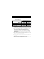
REVISIONS
* The manual number is noted at the lower right of the top cover.
Print Date
*Manual Number
Revision
Mar. 2006
IB(NA)-0800350-A First edition
May. 2006
IB(NA)-0800350-B Partial corrections
Chapter 2
Sep. 2006
IB(NA)-0800350-C Partial addition
Chapter 1
Addition
Compliance with the EMC and Low
Voltage Directives
Jul. 2007
IB(NA)-0800350-D Partial corrections
Compliance with the EMC and Low
Voltage Directives, Chapter 2, 4, 7
This manual confers no industrial property rights or any rights of any other kind,
nor does it confer any patent licenses. Mitsubishi Electric Corporation cannot be
held responsible for any problems involving industrial property rights which may
occur as a result of using the contents noted in this manual.
© 2006 MITSUBISHI ELECTRIC CORPORATION
A-6
CONTENTS
1. Overview ........................................................................................................ 1
2. Specifications ................................................................................................. 2
3. Part Names .................................................................................................... 4
4. Installation Procedure .................................................................................... 8
5. Precautions for Laying Cables ..................................................................... 10
5.1 Precautions for cable connection (GT15-J71LP23-25) ......................... 10
5.2 Precautions for cable connection (GT15-J71BR13) .............................. 12
6. Wiring Method .............................................................................................. 14
7. External Dimensions .................................................................................... 15
A-7
Manuals
The following shows manuals relevant to this product.
Detailed Manual
Manual number
(Model code)
Manual name
GT15 User's Manual
(Sold separately)
SH-080528ENG
(1D7M23)
(Sold separately)
SH-080532ENG
(1D7M26)
GOT1000 Connection Manual
Relevant Manuals
For relevant manuals, refer to the PDF manual stored within the drawing
Compliance with the EMC and Low Voltage Directives
When incorporating the Mitsubishi GOT into other machinery or equipment and
keeping compliance with the EMC and low voltage directives, refer to "EMC
AND LOW VOLTAGE DIRECTIVE" of GT15 User's Manual.
The CE logo is printed on the rating plate of the GOT, indicating compliance with
the EMC and low voltage directives.
A-8
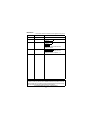
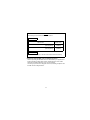
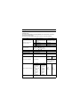
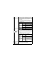
Packing List
The following items are included.
Model
GT15-J71LP23-25
GT15-J71BR13*1
Product
Quantity
MELSECNET/H communication unit
1
Mounting screw set (2 screws, 2 stickers)
2
Extend interface relay board
1
MELSECNET/H communication unit
1
F-type connector (A6RCON-F)
1
Mounting screw set (2 screws, 2 stickers)
2
Extend interface relay board
1
*1 : In the case of coaxial-type network system, terminal resistors must
be attached to both terminal stations of the network. The GT15J71BR13 does not include terminal resistors (A6RCON-R75:75 ).
Therefore, they should be prepared by the user.
A-9
1. Overview
This manual explains the GT15-J71LP23-25 and GT15-J71BR13 (hereinafter
referred to as MELSECNET/H communication unit).
The MELSECNET/H communication unit allows the GOT 1000 series to
function as a normal station (MELSECNET/H connection, MELSECNET/10
connection) in the MELSECNET/H network system (PLC to PLC network) and
MELSECNET/10 network system (PLC to PLC network).
Refer to GT15 User's Manual for GOT to which this unit can be installed.
When using the MELSECNET/H or MELSECNET/10 connection, make the
communication setting to perform communication with PLCs.
For system configuration when connecting the GOT to the MELSECNET/H or
MELSECNET/10 system, refer to GOT1000 Series Connection Manual.
1
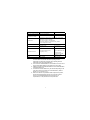
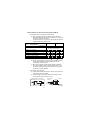
2. Specifications
The performance specifications of the MELSECNET/H communication unit are
indicated below.
The general specifications of the MELSECNET/H communication unit are the
same as those of the GOT.
For the general specifications of the GOT, refer to GT15 User's Manual. *1
Item
Maximum number of link
points per network
Maximum number of link
points per station
GT15-J71LP23-25
MELSECNET/H mode
MELSECNET/H Extended
mode*2
GT15-J71BR13
MELSECNET/H mode*2
LX/LY
8192 points
8192 points
LB
16384 points
8192 points
LW
16384 points
8192 points
• MELSECNET/H mode, MELSECNET/10 mode
{(B+Y)
8+(2
W)}
2000 bytes
{(B+Y)
8+(2
W)}
35840 bytes
• MELSECNET/H Extended mode
Communication speed
10Mbps/25Mbps*3
10Mbps
Communication method
Token ring method
Token bus method
Synchronous method
Frame synchronous
Type of transmission
channel
Double loop (Optical fiber cable)
Coaxial single bus
3C-2V:
300m
(984.3ft)
Total extension distance
Distance between stations*4
Accessible network range
30km (98430ft)
5C-2V:
500m
(1640.5ft)
Repeater module
(A6BR10, A6BR10-DC)
Maximum expansion is
2.5km (8203ft)
During 25Mbps
During 10Mbps
SI optical cables
:200m(656.2ft)
H-PCF optical
cables
:400m(1312.4ft)
Broad-band
H-PCF optical
cables
:1km(3281ft)
QSI optical
cables
:1km(3281ft)
SI optical cables
:500m(1640.5ft)
H-PCF optical
cables
3C-2V:
:1km(3281ft)
300m
Broad-band
(984.3ft)
H-PCF optical
cables
:1km(3281ft)
QSI optical
cables
:1km(3281ft)
5C-2V:
500m
(1640.5ft)
Only the MELSECNET/H or MELSECNET/10 network system
to which the GOT is connected
2
Item
GT15-J71LP23-25
GT15-J71BR13
Maximum number of groups 0 (No group specification)
Number of stations
connected to a network
63 stations
RAS functions
• Prevention of system down by switching the control station
• Loopback in case of error detection or cable disconnection
(Specific to GT15-J71LP23-25)
• Link channel check for the host station
• Abnormality detection by link special relay, resistor
• Various diagnostic functions
31 stations
Transient transmission
• N:N communication
Cable
Optical fiber cable
(Arranged by user*5)
3C-3V 5C-2V or
equivalent
2-core optical connettor plug
(Arranged by user*5)
BNC-P-3-NiCAu (For 3C2V)
BNC-P-5-NiCAu (For 5C2V)
Equivalent goods
(manufactured by DDK
Electronics., LTD.)
Applicable connectors
Internal current consumption 0.56A
0.77A
Weight
0.19kg (0.38lb)
0.18kg (0.36lb)
*1 : When installing an extension unit on the MELSECNET/H
communication unit, limit the maximum operating ambient
temperature by subtracting 5 degrees from operating ambient
temperature of the general specifications.
*2 : The mode of the MELSECNET/H communication unit can be set in
the Communication Settings of GT Designer2 or GOT utility.
*3 : 25Mbps is applied to the MELSECNET/H mode and MELSECNET/
H Extended mode only.
*4 : The distance between stations may be restricted depending on the
type of the cable or the number of connected stations. (Refer to
Section 5.1 (1), Section 5.2 (1).)
*5 : Please note that use of optical fiber cable requires the expertise,
special tools and dedicated connector for connection. Please
contact your local Mitsubishi Electric System Service or
representative, for the purchase of the required items.
3
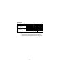
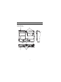
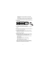
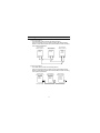
3. Part Names
The following describes part names and LED indications of the MELSECNET/H
communication unit.
1) GT15-J71LP23-25
5)
7)
5)
6)
8)
7)
1)
2)
4
4)
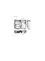
2) GT15-J71BR13
5)
7)
4)
5)
6)
8)
7)
1)
3)
5
No.
Name
Description
This indicates the status of the MELSECNET/H communication
unit and the communication status.
When the LED is lighted up, there are two display formats, one for
the normal mode and the other for the error mode.
(1) Normal Mode
If any communication error occurs in the normal mode, specify
the error cause by the [NETWK unit status display] screen.
Refer to GT15 User's Manual for details on the [NETWK unit
status display] screen.
LED name
RUN
L ERR.
SD
1)
Operation indicator
LED
SD
RD
RD
Status
Description
Off
The GOT is being reset.
Lighted up
The unit is in a normal status.
Off
The unit is in a normal status.
Lighted up
A communications error has
occurred.
Off
Data not transmitted.
Lighted up
Data are being transmitted.
Off
Data not received.
Lighted up
Data are being received.
(2) Error mode
When the RUN LED is blinking, the LED display format is the
error mode.In the error mode, if an error occurs, restart the
RUN
GOT.
L ERR.
If the error mode is not released after restarting the GOT, the
system alarm "460 Communication unit error" may has
occurred.
For system alarms, refer to GT15 User's Manual.
LED name
RUN
Status
Blinking
Description
Shows that it is in the error
mode.
Off Lighted up No error
L ERR.
Off
A starting error has not
occurred.
Lighted up
A starting error has occurred.
Off
A hard ware failure has not
occurred.
Lighted up
A hard ware failure has
occurred.
RD
2)
Connector (IN side,
OUT side)
Connector for connecting an optical fiber cable
(For GT15J71LP23-25 only)
6
No.
Name
Description
3)
Connector
(For GT15J71BR13 only)
4)
Interface connector Extension connector installed to a front extension unit or the GOT
5)
Extension
connector
Connector for attaching the F-type connector to connect coaxial
cables
Extension connector to which a back extension unit is installed
6)
Board fixing screw
Screws for fixing the extension interface relay board
7)
Mounting screw
Mounting screws fixed with a front extension unit or the GOT
8)
Rating plate
-
7
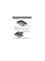
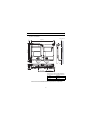
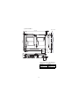
4. Installation Procedure
(1) Power off the GOT.
(2) Remove two extension unit covers of the GOT.
(3) Attach the extend interface relay board to the extend I/F-2 side on the
GOT.
After the installation, detach the connector cover from the extend
interface relay board.
For GT155 , the extend interface relay board is not needed.
(4) Fit the MELSECNET/H communication unit in the GOT case.
Remove the connector cover
4)
3)
(5) Fasten the MELSECNET/H communication unit by tightening its
mounting screws (4 places) with tightening torgue 0.36 to 0.48 N•m.
8
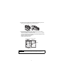
(6) Fasten the bus connection unit by tightening the board fixing screws (2
places) with the tightening torque of 0.36 to 0.48 N•m.
5)
6)
(7) When installing an extension unit on the unit that has been installed,
remove the connector cover and the sticker.
When not installing an extension unit on the unit that has been installed,
in order to avoid receiving electrostatic, stick accessory stickers to cover
the top of mounting screws (4 places).
Keep the connector cover fixed.
Keep the sticker stuck as it is.
Connector cover
Accessory sticker
Sticker
Accessory sticker
Point
Remove the screws that fixes the extend interface relay board before removing the unit.
(Above 6))
9
5. Precautions for Laying Cables
5.1 Precautions for cable connection (GT15-J71LP23-25)
(1) The distance between stations varies depending on the type of
optical-fiber cable used.
Distance between stations [m (ft.)]
Type
SI optical fiber cable
(Old type: A-2P- )
L type
H type
SI optical fiber cable
25Mbps
10Mbps
200 (656)
500 (1640)
100 (328)
300 (984)
200 (656)
500(1640)
H-PCF optical fiber cable
400 (1312)
1000(3281)
Broad-band H-PCF optical fiber cable
1000 (3281)
1000(3281)
QSI optical fiber cable
1000 (3281)
1000(3281)
(2) When connecting an optical-fiber cable, the following restrictions on the
bending radius must be observed.
For further details, contact Mitusubishi Electric System & Service Co.,Ltd.
(3) When laying the optical-fiber cable, do not touch the fiber core of the
cable connector or module connector, or let dirt or dust collect on it.
If oil from the hands, dirt or dust should adhere to the core, the
transmission loss will increase, causing a malfunction in the data link.
Do not remove the covers from the unit connectors without optical-fiber
cables connected.
(4) When attaching or detaching the optical-fiber cable to/from the unit, hold
the cable connector securely with the hands.
(5) Connect the cable connector and unit connector securely until you hear a
"click" sound.
(6) For connecting or removing the optical-fiber cables, be sure to shut off all
phases of the external power supplies used in the system.
10
(7) Please wire IN/OUT of the connector for the cable correctly.
After wiring, perform a loop test or station-to-station test or others to
confirm if the setting and wiring of GT15-J71LP23-25 have been done
properly.
For testing methods, refer to the following manuals.
• Type MELSECNET/10 Network system (PLC to PLC network)
Reference Manual
• For QnA/Q4AR MELSECNET/10 Network System
Reference Manual
• Q Corresponding MELSECNET/H Network System
Reference Manual (PLC to PLC network)
It might be generated that a baton abnormal passing cannot be
generated when miswiring and the downed bureau which cannot do the
loopback of an arbitrary bureau do the row again even by the reclosing of
the power supply.
11
5.2 Precautions for cable connection (GT15-J71BR13)
(1) Restrictions on the cable length between stations
(a) When connecting between the network modules, the cable
lengths indicated in the table below should be used according to
the number of stations connected.
A communication error may occur if a cable length other than the
lengths indicated in the table is used.
Number of stations connected
Station-to-station cable length
Cable type
2 to 9 stations
3C-2V
5C-2V
10 to 32 stations
3C-2V
5C-2V
(cable less than 1m (3.28 ft.) in
length cannot be used.)
0 to 1 m (3.28 ft.)
1 (3.28 ft.) to 5 m (16.4 ft.)
5 (16.4 ft.) to 13 m (42.65 ft.)
13 (42.65 ft.) to 17 m (55.77 ft.)
17 (55.77 ft.) to 25 m (82.02 ft.)
25 (82.02 ft.) to 300 m (984.25 ft.)
300 (984.25 ft.) to 500 m (1640.42 ft.)
: Allowed
: Not allowed
(b) If there is the possibility of an increase in the number of stations
due to system expansion, install the cables with advance
consideration of the restrictions.
(c) When using a repeater module (models A6BR10 or A6BR10DC), use the station-to-station cable length indicated by "10 to
32" stations, regardless of the number of stations connected or
the number of repeater modules.
(2) Precautions for laying cable
(a) Coaxial cables must be laid 100mm (3.9inch) or more apart from
power cables and control cables.
(b) Consider wiring using double-shielded coaxial cable in places
that are subject to large amounts of noise.
Double-shielded coaxial cable
Mitsubishi Cable ... 5C-2V-CCY
Enlarged view
of cable
Sheath
Sheath
Internal
conducter
Insulation External External
material conductor conductor
(Grounding)
Grounding
12
The 5C-2V connector plug is applicable to double-shielded
coaxial cable.
Connect the 5C-2V connector plug to the coaxial cable inside a
double-shielded coaxial cable. Ground the shielded part outside
a double-shielded coaxial cable as shown in the above figure.
(3) Double-shielded caoxial cables have the following restrictions on the
bending radius.
Cable type
Allowable bending radius
r [mm](in.)
3C-2V
23 (0.91)
5C-2V
30 (1.18)
Connector
A[mm](in.)
A
57.5 (2.46)
r
(4) Do not pull any of the connected coaxial cables.
This will cause a faulty contact, cable disconnection, or damage to
the unit.
(5) Make sure to connect a terminal resistor to both terminal stations of
the coaxial bus type network system.
(6) The F type connector has the possibility to extract a white oxide
according to the use enviroment.
However, there is no problem on the function because the oxide is
not generated in connected part.
(7) Please wire the cable correctly.
After wiring, perform a station-to-station test or others to confirm if
the setting and wiring of GT15-J71BR13 have been done properly.
For testing methods, please refer to following manuals.
• Type MELSECNET/10 Network system (PLC to PLC network)
Reference Manual
• For QnA/Q4AR MELSECNET/10 Network System
Reference Manual
• Q Corresponding MELSECNET/H Network System
Reference Manual (PLC to PLC network)
It might be generated that a baton abnormal passing cannot be
generated when miswiring and the downed bureau cannot do the
row again even by the reclosing of the power supply.
13
6. Wiring Method
(1) GT15-J71LP23-25
The optical fiber cable is wired in the following manner.
There is no problem even if not wiring in order of the station number.
Define a control station number and a normal station number according
to the system specifications.
Control station
Station number 1
Normal station
Station number 2
Normal station
Station number 3
QJ71LP
21-25
QJ71LP
21-25
GT15J71LP
23-25
OUT
IN
OUT
IN
OUT
IN
(2) GT15-J71LP23-25
The coaxial cable is wired in the following manner.
There is no program even if not wiring in order of the station number.
Define a control station number and a normal station number according
to the system specifications.
Control station
Station number 1
QJ71
BR13
Normal station
Station number 2
Normal station
Station number 3
QJ71
BR13
GT15J71LP
23-25
Terminal resistor
14
7. External Dimensions
(1) GT15-J71LP23-25
GOT main unit
7(0.28)
133 (5.24)
3
2.5
(0.1)
When the
connector is
connected
When the
connector is
connected
X
9.5
(0.37)
21.5
(0.85)
108 (4.25)
30.5 (1.2)
(3(0.12))
98 (3.86)
(0.12)
49.5 (1.95)
40.3(1.59)
Dimensions of X when the MELSECNET/H
communication unit is mounted to the GOT.
15", 10.4"
21(0.83)
12.1"
18(0.71)
8.4", 5.7"
23(0.91)
Unit:mm (inch)
*Please contact the Mitsubishi Electric System Service Corporation.
15
(2) GT15-J71BR13
GOT main unit
3(0.12)
When the
F type
connedtor
is connected
X
8.5
(0.33)
30.5 (1.2)
21.5 (0.85)
2.5 (0.1)
57.5
(2.26)
98 (3.86)
(12(0.47))
117 (4.61)
7(0.28)
133 (5.24)
17
(0.67)
Dimensions of X when the MELSECNET/H
communication unit is mounted to the GOT.
15", 10.4"
21(0.83)
12.1"
18(0.71)
8.4", 5.7"
23(0.91)
Unit:mm (inch)
16
24(0.94)
(3) Extend interface relay board
27.5(1.08)
64(2.52)
Unit:mm (inch)
17
MITSUBISHI ELECTRIC
HEADQUARTERS
EUROPEAN REPRESENTATIVES
EUROPEAN REPRESENTATIVES
MITSUBISHI ELECTRIC EUROPE B.V.
EUROPE
German Branch
Gothaer Straße 8
D-40880 Ratingen
Phone: +49 (0)2102 / 486-0
Fax: +49 (0)2102 / 486-1120
MITSUBISHI ELECTRIC EUROPE B.V. CZECH REPUBLIC
Czech Branch
Radlická 714/113a
CZ-158 00 Praha 5
Phone: +420 (0)251 551 470
Fax: +420 (0)251-551-471
MITSUBISHI ELECTRIC EUROPE B.V.
FRANCE
French Branch
25, Boulevard des Bouvets
F-92741 Nanterre Cedex
Phone: +33 (0)1 / 55 68 55 68
Fax: +33 (0)1 / 55 68 57 57
MITSUBISHI ELECTRIC EUROPE B.V.
IRELAND
Irish Branch
Westgate Business Park, Ballymount
IRL-Dublin 24
Phone: +353 (0)1 4198800
Fax: +353 (0)1 4198890
MITSUBISHI ELECTRIC EUROPE B.V.
ITALY
Italian Branch
Viale Colleoni 7
I-20041 Agrate Brianza (MI)
Phone: +39 039 / 60 53 1
Fax: +39 039 / 60 53 312
MITSUBISHI ELECTRIC EUROPE B.V.
SPAIN
Spanish Branch
Carretera de Rubí 76-80
E-08190 Sant Cugat del Vallés (Barcelona)
Phone: 902 131121 // +34 935653131
Fax: +34 935891579
MITSUBISHI ELECTRIC EUROPE B.V.
UK
UK Branch
Travellers Lane
UK-Hatfield, Herts. AL10 8XB
Phone: +44 (0)1707 / 27 61 00
Fax: +44 (0)1707 / 27 86 95
MITSUBISHI ELECTRIC CORPORATION
JAPAN
Office Tower “Z” 14 F
8-12,1 chome, Harumi Chuo-Ku
Tokyo 104-6212
Phone: +81 3 622 160 60
Fax: +81 3 622 160 75
MITSUBISHI ELECTRIC AUTOMATION, Inc.
USA
500 Corporate Woods Parkway
Vernon Hills, IL 60061
Phone: +1 847 478 21 00
Fax: +1 847 478 22 53
GEVA
AUSTRIA
Wiener Straße 89
AT-2500 Baden
Phone: +43 (0)2252 / 85 55 20
Fax: +43 (0)2252 / 488 60
TEHNIKON
BELARUS
Oktyabrskaya 16/5, Off. 703-711
BY-220030 Minsk
Phone: +375 (0)17 / 210 46 26
Fax: +375 (0)17 / 210 46 26
Koning & Hartman b.v.
BELGIUM
Woluwelaan 31
BE-1800 Vilvoorde
Phone: +32 (0)2 / 257 02 40
Fax: +32 (0)2 / 257 02 49
INEA BH d.o.o.
BOSNIA AND HERZEGOVINA
Aleja Lipa 56
BA-71000 Sarajevo
Phone: +387 (0)33 / 921 164
Fax: +387 (0)33/ 524 539
AKHNATON
BULGARIA
4 Andrej Ljapchev Blvd. Pb 21
BG-1756 Sofia
Phone: +359 (0)2 / 817 6004
Fax: +359 (0)2 / 97 44 06 1
INEA CR d.o.o.
CROATIA
Losinjska 4 a
HR-10000 Zagreb
Phone: +385 (0)1 / 36 940 - 01/ -02/ -03
Fax: +385 (0)1 / 36 940 - 03
AutoCont C.S. s.r.o.
CZECH REPUBLIC
Technologická 374/6
CZ-708 00 Ostrava-Pustkovec
Phone: +420 595 691 150
Fax: +420 595 691 199
B:TECH A.S.
CZECH REPUBLIC
U Borové 69
CZ-58001 Havlíčkův Brod
Phone: +420 (0)569 777 777
Fax: +420 (0)569-777 778
Beijer Electronics A/S
DENMARK
Lykkegårdsvej 17, 1.
DK-4000 Roskilde
Phone: +45 (0)46/ 75 76 66
Fax: +45 (0)46 / 75 56 26
Beijer Electronics Eesti OÜ
ESTONIA
Pärnu mnt.160i
EE-11317 Tallinn
Phone: +372 (0)6 / 51 81 40
Fax: +372 (0)6 / 51 81 49
Beijer Electronics OY
FINLAND
Jaakonkatu 2
FIN-01620 Vantaa
Phone: +358 (0)207 / 463 500
Fax: +358 (0)207 / 463 501
UTECO A.B.E.E.
GREECE
5, Mavrogenous Str.
GR-18542 Piraeus
Phone: +30 211 / 1206 900
Fax: +30 211 / 1206 999
MELTRADE Ltd.
HUNGARY
Fertő utca 14.
HU-1107 Budapest
Phone: +36 (0)1 / 431-9726
Fax: +36 (0)1 / 431-9727
Beijer Electronics SIA
LATVIA
Vestienas iela 2
LV-1035 Riga
Phone: +371 (0)784 / 2280
Fax: +371 (0)784 / 2281
Beijer Electronics UAB
LITHUANIA
Savanoriu Pr. 187
LT-02300 Vilnius
Phone: +370 (0)5 / 232 3101
Fax: +370 (0)5 / 232 2980
INTEHSIS srl
MOLDOVA
bld. Traian 23/1
MD-2060 Kishinev
Phone: +373 (0)22 / 66 4242
Fax: +373 (0)22 / 66 4280
Koning & Hartman b.v.
NETHERLANDS
Haarlerbergweg 21-23
NL-1101 CH Amsterdam
Phone: +31 (0)20 / 587 76 00
Fax: +31 (0)20 / 587 76 05
Beijer Electronics AS
NORWAY
Postboks 487
NO-3002 Drammen
Phone: +47 (0)32 / 24 30 00
Fax: +47 (0)32 / 84 85 77
MPL Technology Sp. z o.o.
POLAND
Ul. Krakowska 50
PL-32-083 Balice
Phone: +48 (0)12 / 630 47 00
Fax: +48 (0)12 / 630 47 01
Sirius Trading & Services srl
ROMANIA
Aleea Lacul Morii Nr. 3
RO-060841 Bucuresti, Sector 6
Phone: +40 (0)21 / 430 40 06
Fax: +40 (0)21 / 430 40 02
Craft Con. & Engineering d.o.o.
SERBIA
Bulevar Svetog Cara Konstantina 80-86
SER-18106 Nis
Phone:+381 (0)18 / 292-24-4/5
Fax: +381 (0)18 / 292-24-4/5
INEA SR d.o.o.
SERBIA
Izletnicka 10
SER-113000 Smederevo
Phone: +381 (0)26 / 617 163
Fax: +381 (0)26 / 617 163
AutoCont Control s.r.o.
SLOVAKIA
Radlinského 47
SK-02601 Dolny Kubin
Phone: +421 (0)43 / 5868210
Fax: +421 (0)43 / 5868210
CS MTrade Slovensko, s.r.o.
SLOVAKIA
Vajanskeho 58
SK-92101 Piestany
Phone: +421 (0)33 / 7742 760
Fax: +421 (0)33 / 7735 144
INEA d.o.o.
SLOVENIA
Stegne 11
SI-1000 Ljubljana
Phone: +386 (0)1 / 513 8100
Fax: +386 (0)1 / 513 8170
Beijer Electronics AB
SWEDEN
Box 426
SE-20124 Malmö
Phone: +46 (0)40 / 35 86 00
Fax: +46 (0)40 / 35 86 02
Econotec AG
SWITZERLAND
Hinterdorfstr. 12
CH-8309 Nürensdorf
Phone: +41 (0)44 / 838 48 11
Fax: +41 (0)44 / 838 48 12
GTS
TURKEY
Darülaceze Cad. No. 43 KAT. 2
TR-34384 Okmeydanı-Istanbul
Phone: +90 (0)212 / 320 1640
Fax: +90 (0)212 / 320 1649
CSC Automation Ltd.
UKRAINE
15, M. Raskova St., Fl. 10, Office 1010
UA-02002 Kiev
Phone: +380 (0)44 / 494 33 55
Fax: +380 (0)44 / 494-33-66
MITSUBISHI
ELECTRIC
FACTORY AUTOMATION
EURASIAN REPRESENTATIVES
Kazpromautomatics Ltd.
Mustafina Str. 7/2
KAZ-470046 Karaganda
Phone: +7 7212 / 50 11 50
Fax: +7 7212 / 50 11 50
CONSYS
Promyshlennaya st. 42
RU-198099 St. Petersburg
Phone: +7 812 / 325 36 53
Fax: +7 812 / 325 36 53
ELECTROTECHNICAL SYSTEMS
Derbenevskaya st. 11A, Office 69
RU-115114 Moscow
Phone: +7 495 / 744 55 54
Fax: +7 495 / 744 55 54
ELEKTROSTILY
Rubzowskaja nab. 4-3, No. 8
RU-105082 Moscow
Phone: +7 495 / 545 3419
Fax: +7 495 / 545 3419
NPP "URALELEKTRA"
Sverdlova 11A
RU-620027 Ekaterinburg
Phone: +7 343 / 353 2745
Fax: +7 343 / 353 2461
KAZAKHSTAN
RUSSIA
RUSSIA
RUSSIA
RUSSIA
MIDDLE EAST REPRESENTATIVES
ILAN & GAVISH Ltd.
24 Shenkar St., Kiryat Arie
IL-49001 Petah-Tiqva
Phone: +972 (0)3 / 922 18 24
Fax: +972 (0)3 / 924 0761
ISRAEL
AFRICAN REPRESENTATIVE
CBI Ltd.
Private Bag 2016
ZA-1600 Isando
Phone: + 27 (0)11 / 928 2000
Fax: + 27 (0)11 / 392 2354
SOUTH AFRICA
Mitsubishi Electric Europe B.V. /// FA - European Business Group /// Gothaer Straße 8 /// D-40880 Ratingen /// Germany
Tel.: +49(0)2102-4860 /// Fax: +49(0)2102-4861120 /// [email protected] /// www.mitsubishi-automation.com