1
Imagine3D Users Manual
Ultrasonic Simulation Software
i
.
UTEX Scientific Instruments Inc.
Imagine3D User’s Manual
.
TABLE OF CONTENTS
RELEASE NOTES ..........................................................................................................1
What’s New in Version 2.5.......................................................................................................................3
What's Changed in Version 2.5.................................................................................................................4
INSTALLING ...................................................................................................................5
Installation & Technical Support ..............................................................................................................7
Installation ................................................................................................................................................7
WHAT CAN I DO? ..........................................................................................................9
GETTING STARTED.....................................................................................................13
Getting Started -- Overview....................................................................................................................15
MAIN COMPONENTS...................................................................................................19
Overview of Different Document Types ................................................................................................21
Simulation Documents - Define your inspection....................................................................................22
Target Documents - Define your target's shape and material. ................................................................23
Probe Documents – Define your transmitter and receiver. .....................................................................24
Modes Documents - Define the sound modes to be displayed. ..............................................................25
Simple (2D) Editor– Probes, Modes and Raytracing View ....................................................................26
Simple (2D) Editor – Target View..........................................................................................................27
B-scan Documents - A plot of all arriving echoes over a scanned distance. ..........................................28
Material Properties Table - Edit material velocity, density and attenuation values................................29
Cross-Section Editor – Defines 2D profiles that can be extruded or revolved into 3D solids................30
Workspace Folders -- save everything so that you can continue your work later ..................................31
HOW DO I ? ..................................................................................................................33
Create New Documents (Simulation, Target, Probes, Modes) ...............................................................35
Create targets using only Imagine3D......................................................................................................35
Create targets from imported CAD drawings .........................................................................................36
Setup a DXF file for Import into Imagine3D..........................................................................................36
Create a Revolved or Extruded Cross-Section Part using a text file of points........................................37
Select Pulse Echo or Pitch Catch ............................................................................................................38
Configure an immersion transducer........................................................................................................39
Configure a contact transducer ...............................................................................................................39
Enable desired longitudinal and shear modes .........................................................................................40
Select a sound display mode (rays, wavefronts, beam or pulse).............................................................41
Define a ray’s color (used to highlight the mode type, medium type or generation)..............................42
Move the probe around the target ...........................................................................................................42
Adjust the viewing angle ........................................................................................................................43
Select the A-scan view............................................................................................................................43
Select the Text description view .............................................................................................................44
Produce a printed report..........................................................................................................................45
REFERENCE ................................................................................................................47
B-SCAN DOCUMENTS ................................................................................................49
FILE MENU-B-scan Document .............................................................................................................49
VIEW MENU – B-scan Document.........................................................................................................51
WINDOW MENU-B-scan Document ....................................................................................................51
RF B-SCAN WINDOW ..................................................................................................52
Ultrasonic Simulation Software Version 2.5
i
UTEX Scientific Instruments Inc.
Imagine3D User’s Manual
CROSS-SECTION EDITOR ..........................................................................................55
MATERIAL PROPERTIES DOCUMENT ......................................................................61
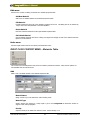
RIGHT CLICK CONTEXT MENU – Materials Table..........................................................................62
MODES DOCUMENT....................................................................................................65
FILE MENU – Modes Document...........................................................................................................65
EDIT MENU – Modes Document ..........................................................................................................67
VIEW MENU – Modes Document.........................................................................................................67
WINDOW MENU – Modes Document..................................................................................................68
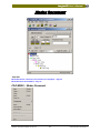
FILE TOOLBAR– Modes Document.....................................................................................................68
RIGHT CLICK CONTEXT MENU – Modes Document.......................................................................70
PROBE DOCUMENT ....................................................................................................71
FILE MENU – Probe Document ............................................................................................................71
EDIT MENU – Probe Document............................................................................................................73
VIEW MENU – Probe Document ..........................................................................................................73
WINDOW MENU – Probe Document ...................................................................................................73
FILE TOOLBAR– Probe Document ......................................................................................................74
ULTRASONICS TAB - Probe Document..............................................................................................75
Beam Cross-Section - Setup ...................................................................................................................76
RF Beam Cross-Section – Window ........................................................................................................77
WEDGE / COUPLING TAB – Immersion - Probe Document ..............................................................79
WEDGE / COUPLING TAB – Wedge - Probe Document ....................................................................79
ELEMENT TAB - Probe Document.......................................................................................................80
LOCATION TAB - Probe Document.....................................................................................................81
SIMPLE EDITOR...........................................................................................................83
FILE MENU – Simple Editor Raytracing View.....................................................................................84
EDIT MENU – Simple Editor Raytracing View ....................................................................................85
VIEW MENU – Simple Editor Raytracing View...................................................................................86
FORMAT MENU – Simple Editor Raytracing View.............................................................................88
TOOLS MENU - Simple Editor Raytracing View .................................................................................91
BEHAVIOR MENU – Simple Editor Raytracing View.........................................................................92
WINDOW MENU – Simple Editor Raytracing View............................................................................93
FILE TOOLBAR– Simple Editor Raytracing View...............................................................................93
VIEW TOOLBAR – Simple Editor Raytracing View............................................................................96
PROBE TOOLBAR – Simple Editor Raytracing View .........................................................................97
MAIN VIEWS TOOLBAR – Simple Editor Raytracing View ..............................................................98
CONTACT/IMMERSION TAB – Immersion – Probe Window Simple Editor Raytracing View ........98
CONTACT/IMMERSION TAB – Contact – Probe Window Simple Editor Raytracing View.............99
WEDGE TAB –Probe Window Simple Editor Raytracing View...........................................................99
ELEMENT TAB –Probe Window Simple Editor Raytracing View ....................................................100
LOCATION TAB –Probe Window Simple Editor Raytracing View...................................................101
VIEW CONTROL BAR- Simple Editor Raytracing View ..................................................................101
IMAGINE3D STATUS BAR – Simple Editor Raytracing View.........................................................102
RIGHT CLICK CONTEXT MENU – Simple Editor Raytracing View...............................................102
RIGHT CLICK CONTEXT MENU – Simple Editor A-scan View.....................................................103
RIGHT CLICK CONTEXT MENU – Probe Simple Editor Raytracing View ....................................103
RIGHT CLICK CONTEXT MENU – Modes Window Simple Editor Raytracing View ....................104
UTEX Scientific Instruments Inc.
ii
Ultrasonic Simulation Software Version 2.5
Imagine3D User’s Manual
.
SIMPLE EDITOR – TARGET VIEW............................................................................105
FILE MENU – Simple Editor – Target View .......................................................................................106
EDIT MENU – Simple Editor – Target View ......................................................................................107
VIEW MENU – Simple Editor – Target View .....................................................................................108
FORMAT MENU – Simple Editor – Target View...............................................................................109
TOOLS MENU - Simple Editor – Target View ...................................................................................109
BEHAVIOR MENU – Simple Editor – Target View...........................................................................110
WINDOW MENU – Simple Editor – Target View..............................................................................110
FILE TOOLBAR– Simple Editor – Target View.................................................................................111
VIEW TOOLBAR – Simple Editor – Target View..............................................................................111
PARTS TOOLBAR – Simple Editor – Target View............................................................................112
EDIT PARTS TOOLBAR – Simple Editor – Target View..................................................................112
RIGHT CLICK CONTEXT MENU – Simple Editor – Target View...................................................115
SIMULATION DOCUMENT.........................................................................................117
FILE MENU – Simulation Document ..................................................................................................118
EDIT MENU – Simulation Document..................................................................................................119
VIEW MENU – Simulation Document ................................................................................................121
FORMAT MENU – Simulation Document ..........................................................................................125
TOOLS MENU - Simulation Document ..............................................................................................128
BEHAVIOR MENU – Simulation Document ......................................................................................130
WINDOW MENU – Simulation Document .........................................................................................131
FILE TOOLBAR– Simulation Document ............................................................................................131
VIEW TOOLBAR – Simulation Document .........................................................................................134
PROBE TOOLBAR – Simulation Document.......................................................................................135
VIEW CONTROL BAR-Simulation Document...................................................................................135
IMAGINE3D STATUS BAR – Simulation Document ........................................................................136
RIGHT CLICK CONTEXT MENU – 3D View ..................................................................................137
RIGHT CLICK CONTEXT MENU – Text View ................................................................................137
RIGHT CLICK CONTEXT MENU – A-scan View ............................................................................138
RIGHT CLICK CONTEXT MENU – Probe in 3D View ....................................................................138
TARGET DOCUMENT ................................................................................................139
FILE MENU – Target Document .........................................................................................................140
EDIT MENU – Target Document.........................................................................................................142
VIEW MENU – Target Document .......................................................................................................143
FORMAT MENU – Target Document .................................................................................................145
TOOLS MENU - Target Document......................................................................................................145
BEHAVIOR MENU – Target Document .............................................................................................146
WINDOW MENU – Target Document ................................................................................................146
FILE TOOLBAR– Target Document ...................................................................................................147
VIEW TOOLBAR – Target Document ................................................................................................148
PARTS TOOLBAR – Target Document ..............................................................................................149
EDIT PARTS TOOLBAR – Target Document ....................................................................................150
VIEW CONTROL BAR-Target Document..........................................................................................154
IMAGINE3D STATUS BAR – Target Document ...............................................................................155
RIGHT CLICK CONTEXT MENU – Target Document .....................................................................155
INDEX ..............................................................................................................................I
Ultrasonic Simulation Software Version 2.5
iii
UTEX Scientific Instruments Inc.
Imagine3D User’s Manual
.
END-USER LICENSE AGREEMENT
UTEX Scientific Instruments Inc.
IMPORTANT--READ CAREFULLY: This UTEX Scientific Instruments Inc. ("UTEX") End-User License Agreement ("agreement") is a
legal agreement between you (either an individual or a single entity) and UTEX for the UTEX software product identified above
(Imagine3D) and may include associated media, printed materials and "online" or electronic documentation ("software"). By
installing, copying, or otherwise using the software, you agree to be bound by the terms of this agreement. If you do not agree
to the terms of this agreement, please do not install or use the software.
SOFTWARE LICENSE
The software is protected by copyright laws and international copyright treaties, as well as other intellectual property laws and
treaties. The software is licensed, not sold.
1. GRANT OF LICENSE
This agreement grants you the following rights:
a. Software Use. UTEX grants to you (either an individual or an entity) a non-exclusive, non-transferable license to make use of
the software on a single computer. If you have purchased a volume license, then you may use the software on the permitted
number of computers. For example, a "3 pak" license allows you to use the software on up to three computers.
b. Storage/Network Use. You may also store or install a copy of the software on a storage device, such as a network server,
used only to install or run the software on the computers identified in 1(a), over an internal network; however, you must acquire
and dedicate a license for each separate computer on which the software is installed or run from the storage device. A separate
UTEX hardlock key must be provided for every workstation where the Imagine3D software is installed. A license for the
software may not be used concurrently or on different computers. Other than for reason of a machine failure and/or hardware
upgrading, the license for the software cannot be transferred between workstations.
More than one person may use the software provided the software and hardlock key resides on a single dedicated workstation.
2. DESCRIPTION OF OTHER RIGHTS AND LIMITATIONS
a. Unless this product was licensed through an authorized UTEX reseller, the software cannot be resold, distributed or
transferred to another party.
b. Limitations on Reverse Engineering, Decompilation and Disassembly. You may not reverse engineer, decompile, or
disassemble the software, except and only to the extent that such activity is expressly permitted by applicable law
notwithstanding this limitation.
c. Rental. You may not rent, lease, or lend the software to other parties.
d. Support Services. UTEX may provide you with support services related to the software ("Support Services") provided you have
contracted with UTEX for a support and upgrade contract or if you require support within the first 60 days of receiving the
software. Use of Support Services is governed by the UTEX policies and programs, "online" documentation and/or other UTEXprovided materials. Any supplemental software code provided to you as part of the Support Services shall be considered part of
the software and subject to the terms and conditions of this agreement. With respect to technical information you provide to
UTEX as part of the Support Services, UTEX may use such information for its business purposes, including for product support
and development. UTEX will not utilize such technical information in a form that personally identifies you without permission.
e. Termination. Without prejudice to any other rights, UTEX reserves the right to terminate this agreement if you fail to comply
with the terms and conditions of this agreement. UTEX reserves the right to request all original Imagine3D material (including
the hardlock key) be returned to UTEX. UTEX may also terminate this agreement if you fail to pay in full the agreed purchase
price.
3. UPGRADES
If the software is labeled as an upgrade, you must be properly licensed to use a product identified by UTEX as being eligible for
the upgrade in order to use the software. Software labeled as an upgrade replaces and/or supplements the product that formed
the basis for your eligibility for the upgrade. You may use the resulting upgraded product only in accordance with the terms of
this agreement.
4. COPYRIGHT
All title to and copyrights in the software (including but not limited to any images and text incorporated into the software), the
accompanying printed materials and any copies of the software are owned by UTEX. The software is protected by copyright
laws and international treaty provisions. Therefore, you must treat the software like any other copyrighted material with the
exception that you may install the software on a single computer provided you keep the original solely for backup or archival
purposes. You may not copy the printed materials accompanying the software.
Ultrasonic Simulation Software Version 2.5
v
UTEX Scientific Instruments Inc.
Imagine3D User’s Manual
5. DUAL-MEDIA SOFTWARE
You may receive the software on more than one medium. Regardless of the type or size of medium you receive, you may use
only one medium that is appropriate for your single computer. You may not use or install the other medium on another
computer. You may not loan, rent, lease, or otherwise transfer the other medium to another user. Each installation of the
software requires its own hardlock key regardless of the media type.
6. U.S. GOVERNMENT RESTRICTED RIGHTS
The software and documentation are provided with restricted rights. Use, duplication, or disclosure by the Government is
subject to restrictions as set forth in subparagraph(c)(1)(ii) of the Rights in Technical Data and Computer Software clause at
DFARS 252.227-7013 or subparagraphs (c)(1) and (2) of the Commercial Computer Software-Restricted Rights at 48 CFR
52.227-19, as applicable.
7. EXPORT RESTRICTIONS
You agree that you will not and or do not intend to, directly or indirectly, export or transmit the software or related
documentation and technical data, or process, or service that is the direct product of the software, to any country to which such
export or transmission is restricted by any applicable U.S., Canadian or other State regulation or statute, without the prior
written consent, if required, of the Bureau of Export Administration of the U.S. Department of Commerce, or any other
government entity as may have jurisdiction over such export or transmission.
8. MISCELLANEOUS
This agreement is governed by the laws of the Province of Ontario and the parties agree to resolve any dispute exclusively in
the courts in Toronto, Ontario, Canada.
If this product was acquired outside the United States or Canada, local laws may apply.
Should you have any questions concerning this agreement, or if you wish to contact UTEX for any reason, please contact the
UTEX subsidiary serving your country, or write to: UTEX Scientific Instruments Inc., 2319 Dunwin Drive, Unit 8, Mississauga
Ontario, Canada, L5L 1A3
9. LIMITED WARRANTY
LIMITED WARRANTY. UTEX warrants that (a) the software will perform substantially in accordance with the accompanying
written materials for a period of sixty (60) days from the date of receipt and (b) any Support Services provided by UTEX shall be
substantially as described in applicable written materials provided to you by UTEX and UTEX support engineers will make
commercially reasonable efforts to solve any problem issues. To the extent allowed by applicable law, implied warranties on the
software, if any, are limited to sixty (60) days.
CUSTOMER REMEDIES. UTEX’ and its suppliers’ entire liability and your exclusive remedy shall be, at UTEX’ option, either (a)
return of the price paid, if any, or (b) repair or replacement of the software that does not meet UTEX’ Limited Warranty and that
is returned to UTEX with a copy of your receipt. This Limited Warranty is void if failure of the software has resulted from
accident, abuse, or misapplication. Any replacement software will be warranted for the remainder of the original warranty
period or thirty (30) days, whichever is longer. Outside the United States and Canada, neither these remedies nor any product
support services offered by UTEX are available without proof of purchase from an authorized source.
NO OTHER WARRANTIES. To the maximum extent permitted by applicable law, UTEX and its suppliers disclaim all other
warranties and conditions, either express or implied, including, but not limited to, implied warranties of merchantability, fitness
for a particular purpose, title and non-infringement, with regard to the software and the provision of or failure to provide
support services.
10. LIMITATION OF LIABILITY
To the maximum extent permitted by applicable law, in no event shall UTEX or its suppliers be liable for any special, incidental,
indirect, or consequential damages whatsoever (including, without limitation, damages for loss of business profits, business
interruption, loss of business information, or any other pecuniary loss) arising out of the use of or inability to use the software or
the provision of or failure to provide support services, even if UTEX has been advised of the possibility of such damages. In any
case, UTEX’ entire liability under any provision of this agreement shall be limited to the greater of the amount actually paid by
you for the software or US$5.00
UTEX Scientific Instruments Inc.
vi
Ultrasonic Simulation Software Version 2.5
Imagine3D Users Manual
.
Release Notes
Ultrasonic Simulation Software
1
UTEX Scientific Instruments Inc.
Imagine3D User’s Manual
.
What’s New in Version 2.5
Selection of objects
To move any object in Imagine3D, including probes, the object must first be selected. Objects can be selected
using the mouse by moving the cursor over the object and double-clicking it. Objects that are selected are shown
in bold lines and have black mouse handles. Ctrl-double-click allows you to select more than one object so that
they can be moved at the same time. Pressing the tab key changes the selected object. No object can be moved
or altered unless it is first selected.
Simple I2D View Editor
A new Simple View Editor provides the main elements of Imagine3D limited to a front top or side view. The
four windows include A-scan, Raytracing, Modes and Probe views. The Target can only be edited in the front
view.
Probe Reflections
The probe front surface and the sides of the wedge are now reflecting surfaces that allow you to fully simulate
probe and water multiples. Internal reflections inside the wedge are also modeled.
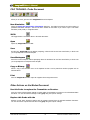
Gain buttons
Two new Gain buttons on the View Toolbar allow you to easily increase or decrease the A-scan gain in 3dB
steps.
Wedge Editor
The Edit Probe X-Sec button in the Probe document allows you to change the shape of the wedge using the
cross-section editor. You may add and change certain line segments. Wedge length, acceptance angle and
element size indicated in the Edit Probe dialog box are preserved.
Pulse Animation
Ray propagation can now be animated continuously. You may now specify time limits for the pulse animation
loop.
Importing of solids using SAT files
Imagine3D now provides .SAT file support using Spatial Technologies Inc. ACIS solid modeling engine. This is
the same solid modeling engine used by AutoCAD, CadKey and other major CAD packages (Some CAD packages
provide conversions from IGES and other formats to .SAT).
I3D Viewer files
Imagine3D can now create a viewer file (.i3d) that you can share with those who do not own Imagine3D.
Look for free viewer software that will be available for download from our website www.utex.com. The viewer
displays information about a simulation including the target, probe, A-scan and pulse animation. I3D viewer files
can be placed into Microsoft Word documents to provide accurate simulation information for technique
development and simulation reporting. I3D viewer files can also be opened as a full simulation by those who own
Imagine3D.
Probe Coupling Depth
The depth that a probe wedge overlaps the target can now be set using the Set Coupling Depth button on the
Probe Wedge tab or the Edit - Set Coupling Depth menu when editing a probe. This function simply makes
sure that the wedge is in full contact with the surface of a curved target by allowing you to specify the targetwedge overlap in the simulation.
Ultrasonic Simulation Software Version 2.5
3
UTEX Scientific Instruments Inc.
Imagine3D User’s Manual
What's Changed in Version 2.5
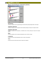
Dragging
In the Simulation View, the probes, labels, lines and coordinates can be dragged once selected. To select any
object, move the mouse cursor over that object and double-click. To select an additional object, move your
mouse over the new object and hold the Ctrl key while you double-click that object. When any object is selected,
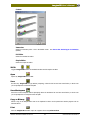
black handles appear which can be used to manipulate that object. The Probe handles allow the rotation of the
probe itself or rotation of the probe around the origin. The TAB key also allows users to individually select each of
the objects in the view. For labels and lines, the outside black handles allow you to resize an object. The mouse
cursor changes to indicate what will occur when the mouse button is depressed at the current location.
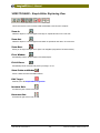
Grouping Objects
New group and ungroup buttons allow you to group the probes and labels together. The groups will move
according to the movement behavior properties of the object the mouse is over. You may make groups of
groups. The ungroup button ungroups and deselects all the objects in a group.
A-scan
You can now turn the wedge delay on or off. This sets the A-scan zero-point to either the surface of the probe or
the surface of the wedge. Dragable cursors have been added. These correspond to the current propagation time
(green line) or twice the propagation time (blue line). The cursors become active when animating a pulse or
when you have asked rays to end at a particular time. Also, the B-scan gate can now be hidden.
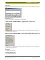
Cross-Section Editor
The cross-section editor now uses a grid control to display and edit the points in the cross-section. You can
edit the cross-section using the mouse on the display window or by typing directly into the grid to adjust the
points. The editor no longer automatically zooms the view to fit the cross-section.
Target Document
The list box now contains all of the target parts and indicates which are currently selected. The Parts Toolbar and
Edit Part toolbar allow easy access to commonly used functions. Target parts can now be selected, dragged,
resized and rotated using mouse clicks.
Surface Following
A transducer’s ability to “stick to” and align itself on curved surfaces when using a contact transducer has been
enhanced. Contact transducers can now follow almost any surface without jumping or losing contact with the
surface. Simulated inspections of curved surfaces, such as boilers or tubes, can be performed with little or no
“lift-off” occurring. Surface following is not active when spinning or rotating a probe.
Label, Line and Title Editing
Labels and titles can now have properties such as position, size and content edited rather than replaced. A line’s
length, position and color can also be edited.
UTEX Scientific Instruments Inc.
4
Ultrasonic Simulation Software Version 2.5
Imagine3D Users Manual
.
Installing
Ultrasonic Simulation Software
5
UTEX Scientific Instruments Inc.
Imagine3D User’s Manual
.
Installation & Technical Support
Welcome to Imagine3D Ultrasonic Simulation Software
Imagine3D 2.5 offers a large range of simulation options. To help you learn most effectively, this
documentation system offers on-line help topics, tutorial movies, sample simulations and a printed or PDF format
manual.
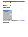
Installation
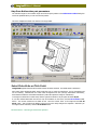
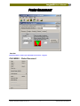
Imagine3D now has an "Auto Run" feature on the CD that launches a user interface. All of the installation
options are available through this interface. You can view the training movies and the manual without installing
Imagine3D. The manual is provided in a PDF (Adobe Acrobat) format so that it can be easily viewed online or
printed if necessary.
If you are installing for the first time, please insert the CD and choose the installation option from the
interface that appears. If you are upgrading to Version 2.5, please install Version 2.5 without removing your
previous version.
If you are installing Imagine3D Version 2.5 into a new folder location, proceed with the installation. Move your
existing .ray files to the new Version 2.5 folder. Delete any remaining old Imagine3D Version folders using
Windows Explorer.
If the Imagine3D CD does not launch automatically, browse the CD and run Launch.exe.
Support patch files will be available on our web site at www.utex.com
Free yearly upgrades and support are available to customers who have purchased I3DCoverage. For information
about Imagine3D coverage, please contact us at the address noted below.
Your Hardlock Key
The Hardlock key is a small (1-3/4" x 2-1/4") hardware device that prevents Imagine3D from being copied and
used illegally. This device, also known as a “Dongal”, attaches directly to your computer’s parallel port. The
printer is then attached to the Hardlock key. The Hardlock key does not interfere with printer operations.
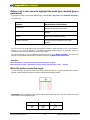
Minimum System Requirements:
Recommended System Requirements:
Pentium90
200MHz Pentium II or faster
32MB RAM
128MB RAM
VGA Graphics 1024x768 resolution or higher
VGA Graphics 1024x768 resolution or higher
Parallel Port (for hardlock key)
Parallel Port (for hardlock key)
Windows 95 v4.00.950b or later operating system
Windows 95, 98 or NT
If you experience problems, please contact us at:
UTEX Scientific Instruments Inc.
2319 Dunwin Drive, Unit 8
Mississauga, Ontario
Canada, L5L 1A3
Tel: (905) 828-1313
Fax: (905) 828-0360
E-mail: [email protected]
Ultrasonic Simulation Software Version 2.5
7
UTEX Scientific Instruments Inc.
Imagine3D Users Manual
.
What Can I Do?
Ultrasonic Simulation Software
9
UTEX Scientific Instruments Inc.
Imagine3D User’s Manual
.
Develop ultrasonic inspection techniques using real-world parts
Imagine3D was developed to solve a range of everyday problems encountered during ultrasonic inspections
from simple welds to the most difficult composite airframes. Imagine3D allows you to develop an inspection
technique with the benefit of understanding how potential problems such as shadowing and internal multiples
might limit your real-world results.
The inspected parts and probes you will be simulating are your own. Imagine3D takes you through the same
steps as you would experience in the real world, with the added benefit of being able to see where the sound is
actually going inside the part. It is nice to be able to try various probe angles or focal lengths before ordering
probes or fixturing.
Check our Website www.utex.com for additional help movies about technique development
Visualize sound paths in the inspected part
Simulated inspections can be rotated to any viewing angle thereby allowing you to clearly see whether your
inspection technique is doing what you think it is doing.
Imagine3D shows you exactly where the ultrasound is going by using longitudinal, shear and mode-converted
waves. Each new wave generation is displayed in a different color for clarity.
Sound can be displayed as rays, as wavefronts, as a beam profile and as a propagating wave.
See demo movie – Rotating, spinning and tilting the inspection in 3D space
See demo movie – Switching between sound display modes
Diagnose difficult problems by confirming the source of returning
echoes
Imagine3D can accurately identify the origin of unexplained echoes by showing any number of mode-converted
longitudinal or shear waves. A simple yet powerful color B-scan display shows you the times of signals arriving
back at the transducer. The colors on the B-scan correspond to the colors of the rays in the simulation view. You
can directly measure the arrival times of the echoes by moving the cursor between signals shown on the B-scan.
To see what the simulated ultrasonic signals look like, switch the B-scan display into RF mode. In this mode, it is
also possible to see all of the collected A-scans that make up the B-scan.
These tools make it possible to solve the problem of echo overlap, where quite often it is just a matter of
choosing a slightly different focal length or probe angle.
See demo movie – Viewing A-scans and arrival times
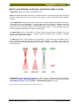
Model transducer sound fields for making transducer choices
Imagine3D will simulate the beam profiles of transducers that you already own, thereby allowing you to
determine if any of them are able to do the job for a given inspection. If not, Imagine3D can help you
determine the transducer you will need to order. This eliminates expensive errors such as ordering transducers
with focal lengths or beam spreads that do not provide optimum sensitivity or coverage.
The probes can be anything that you might have on the shelf or that you can order from a catalog. The success
of your inspection technique is aided by discovering how various angles, mode conversions and focal lengths
affect the simulated A-scan signals.
A beam profile is primarily used to demonstrate the transducer’s focus quality and the depth-of-field within the
inspection part.
See demo movie – Viewing the beam cross-section of a transducer
See demo movie – Using the text view
Ultrasonic Simulation Software Version 2.5
11
UTEX Scientific Instruments Inc.
Imagine3D User’s Manual
Simulate a complete ultrasonic inspection
Imagine3D’s features can completely simulate your inspection technique so that you can save time and make
fewer errors.
Simulated B-scans can show you how flaws might be accidentally shadowed by part geometry or unwanted mode
conversions. Simulated B-scans quickly show you which of the selected modes are returned as the probe moves
across the surface of the inspected part.
After generating a B-scan, you can save it as a Winspect file. This allows you to use Winspect software for
side-by-side comparison of the simulated B-scan with the real inspection B-scan. Winspect is data acquisition
and imaging software for NDE. Visit our Web site www.utex.com for a complete product description.
Communicate your plans to customers and inspection team
Imagine3D offers printed reports with simulated A-scans, B-scans and raytracing to provide the tools that you
can use to better communicate with your inspection team and customers. If fixturing is required, Imagine3D
reports can list the probe angles, spacing and water-path dimensions needed for fabrication.
You can copy text and graphics to the clipboard for pasting into other applications such as Microsoft Word or
Excel. A fully documented report can be created in a matter of minutes.
See demo movie – Previewing how a report will print
See demo movie – Copying to the clipboard
Train others in ultrasonic theory
Imagine3D makes it simple to demonstrate that by exceeding critical angles, longitudinal and shear waves cease
to be generated. Students can be asked to demonstrate their understanding of applied ultrasonic theory by using
Imagine3D to simulate refraction, reflection, attenuation and the near-field effect.
See demo movie – Simulating critical angle
UTEX Scientific Instruments Inc.
12
Ultrasonic Simulation Software Version 2.5
Imagine3D Users Manual
.
Getting Started
Ultrasonic Simulation Software
13
UTEX Scientific Instruments Inc.
Imagine3D User’s Manual
.
Getting Started -- Overview
Getting started with Imagine3D is actually quite easy. At any time, you can change the inspected part
geometry, transducer characteristics or sound modes to be displayed in the simulation view. If you go down the
wrong path, you never need to start over from the beginning, just change what needs to be changed. The
following sequence will get you up and running quickly.
Here are the five basic steps needed to get you using Imagine3D:
Step One: Create a new default Simulation
Step Two: Edit your Target (define the part to be inspected)
Step Three: Edit your Probes (define the transducers)
Step Four: Edit your Modes (decide which modes to display)
Step Five: Start inspecting the target by moving the transducer around
See Demo Movie: Creating a New Simulation
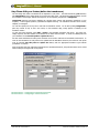
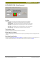
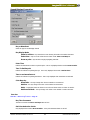
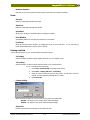
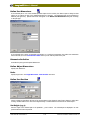
Step One: Create a new default Simulation
Imagine3D stores all of the components needed for an ultrasonic simulation in a single document called a
Simulation document (.ray extension). The fastest way to make a new simulation is to use the New Simulation
button on the Main toolbar. On clicking this button, Imagine3D will display the Choose the desired type of
simulation dialog box. Using this dialog box you can select from a few basic simulation set-ups. You will need
to make a few choices here.
•
Choose between Normal Beam – Pulse Echo, Angle Beam – Pulse Echo, Angle Beam-Pitch Catch.
•
Select a Contact or Immersion simulation.
•
If you chose a Contact simulation, you can select the wave mode type to be Shear or Longitudinal.
•
Choose Full Editor.
On selecting OK, Imagine3D will create a simulation with the default target step block and your chosen
probe(s). If you selected Blank, no default target will appear. The only thing in your new simulation will be a
probe pointing down the Y-axis.
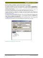
Step Two: Edit your Target (define the part to be inspected)
To edit the target use the Edit Target context menu (right click) or the Edit – Target menu item. The target
document will appear. The target document (.trg extension) describes the shape of your inspection part and the
materials of which it is constructed. The target could simply be a drawing of your inspection part, which may or
may not contain simulated flaws. It could also be a drawing of just the flaw if all that you were interested in was
how sound reflects from the flaw’s surfaces.
A target is any assembly of parts. You can control the part’s material, the way it combines with other parts as
well as the part’s shape. The Parts toolbar provides you with the option of several standard primitive parts. Add
a primitive part into your target by clicking on the part type and dragging the mouse over the area of the target
where you would like to add the new part.
Imagine3D provides these four options for creating and editing targets:
•
Assemble targets from a range of primitive shapes.
•
Import drawings as 3D solids from 3D SAT files or 3D DXF file surfaces that can be generated using
AutoCAD.
•
Import 2D DXF files and extrude or revolve them into 3D solids.
•
Select parts from a library of stock objects and modify them.
Once your edits are complete, the edited target needs to be inserted into the Simulation document using the
Insert this target into button. This will put the new target into the Simulation document and the Target
document can now be closed without losing the new information.
Ultrasonic Simulation Software Version 2.5
15
UTEX Scientific Instruments Inc.
Imagine3D User’s Manual
Step Three: Edit your Probes (define the transducers)
The next thing that needs to be defined in the inspection is your probe. The Probe document (.prb extension)
tells Imagine3D all of the details about the sound source being used. This document feeds information such as
the transducer’s focal length, diameter and frequency to the raytracing components of Imagine3D.
Imagine3D raytracing and beam modeling can simulate both contact and immersion transducers of any
frequency. It also supports spherical, cylindrical and elliptical focusing. The transducer elements can be circular,
elliptical, or rectangular.
You can also specify how the rays are to exit from the transducer surface. You do this by telling Imagine3D to
place any number of rays on the X and Y-axes, on the transducer edge, evenly spaced or randomly on the
transducer surface.
To open the Probe document, select Edit – Probe in the Simulation document main menu. The probe size,
shape, frequency and other details can be defined in the Probe document tabs. To insert the edited probe into
your simulation use the Use this probe to replace the button.
For Pitch Catch simulations the same probe document can be used to edit both the Transmitter and Receiver. In
order for the information for both probes to be updated into the Simulation document, the values for each probe
must be inserted (Use this probe to replace the button) with the appropriate transducer type selected
(transmitter or receiver).
Once the probes have been edited and inserted into the Simulation document, the probe document can be closed
without losing the changes made to the probes.
See demo movie – Configuring an immersion transducer
See demo movie – Configuring a contact transducer
UTEX Scientific Instruments Inc.
16
Ultrasonic Simulation Software Version 2.5
Imagine3D User’s Manual
.
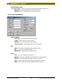
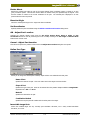
Step Four: Edit your Modes (decide which modes to display)
The next thing to be defined in your inspection is the desired modes. To edit the modes, select Edit – Modes on
the Simulation document’s main menu. The Modes document (extension .mds) tells Imagine3D which
longitudinal and shear wave modes should be displayed. It also describes which transmitted and reflected
wavefronts should be displayed.
The requested modes (longitudinal or shear) are represented graphically just like the branches on a tree. You
have the option of starting a new branch at each interface where different materials come in contact.
By placing unique branches on separate tabs, it is possible to simulate just one branch of the sound path or any
combination of branches. As an example, you can separate corner reflector signals from back-wall multiples that
might be cluttering the A-scan.
The Modes Document Context Menu provides quick access to most of the Modes document options. Modes
can be added to any branch using the modes buttons. To use the preset mode subsets in Imagine3D, just
select one from the predefined modes pull-down list. Using the predefined modes will over-write the current
subset and any other changes you have already made.
The Apply All modes To: button will insert the changes into the Simulation document. Once the changes have
been inserted into your simulation, you can close the Modes document without losing your changes.
See demo movie – Selecting which modes to show
Ultrasonic Simulation Software Version 2.5
17
UTEX Scientific Instruments Inc.
Imagine3D User’s Manual
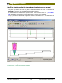
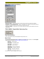
Step Five: Start inspecting the target by moving the transducer around
By this stage, you should be able to see your target in the Simulation view on your monitor. A probe should be
floating in free space somewhere near the target. If this is not the case, click the Fit To Window toolbar button.
Imagine3D will zoom out so that the transducer and target fill the window.
You must first select the transducer before you can move it. This is new since version 2.0. (See – Move a
probe) Double-click on the transducer or press TAB until what you want to move is highlighted.
An easy way to move the transducer left or right and up or down is with the arrow keys. You can also rotate the
probe by holding down the shift or ctrl keys while pressing the arrow keys.
See demo movie – Using the text view
See demo movie – Viewing A-scans and arrival times
UTEX Scientific Instruments Inc.
18
Ultrasonic Simulation Software Version 2.5
Imagine3D Users Manual
.
Main Components
Ultrasonic Simulation Software
19
UTEX Scientific Instruments Inc.
Imagine3D User’s Manual
.
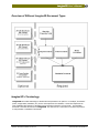
Overview of Different Imagine3D Document Types
Imagine3D’s Terminology
Imagine3D uses certain terminology to describe files and operations it can perform. For example, “Documents”
(Probe, Target, Modes, Simulation, etc.) are the sub-components of a simulation. These sub-components can
exist as individual files outside of a simulation and are therefore referred to as “Documents”. The Simulation
Document is the main file structure for Imagine3D. It is referred to as a “Document: in the same way a file for
a word processor is considered a “Document”.
Ultrasonic Simulation Software Version 2.5
21
UTEX Scientific Instruments Inc.
Imagine3D User’s Manual
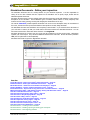
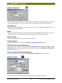
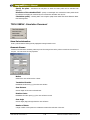
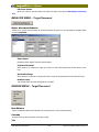
Simulation Documents - Define your inspection.
The Simulation document acts as a viewing window for your ultrasonic inspection. It is also responsible for
storing all of the other elements that are required for the simulation such as probe, target, modes and the
Material Properties documents.
Simulation document views can have multiple panes that show raytracing, sound field modeling, A-scans and text
descriptions of the simulation. Several different types of toolbars provide buttons for many frequently used
functions such as saving, printing, zooming and changing the characteristics of the rays.
The various status bars provide important information such as the current workspace name, the coordinates of
the cursor, the time that the rays end and whether a beam profile is currently being calculated.
The Simulation document can stand alone since everything is stored inside. If you wanted to share the basics of
your work with co-workers, all that you would need to send them would be the Simulation document. You can
also create a viewer file to share with others who don’t own Imagine3D.
Simulation documents do not store how your screen was last configured nor do they store B-scans. Workspaces
organize your screen layout. They also store additional windows such as B-scans. B-scan documents (extension
.bsn) can be regenerated or saved separately.
Simulation documents are given the .ray filename extension.
See also:
Target Documents – Define your target’s shape and material. – Page 23
Probe Documents – Define your transmitter and receiver. – Page 24
Modes Documents – Define the sound modes to be displayed. – Page 25
Simple (2D) Editor – Probes, modes and raytracing view. – Page 26
B-scan Documents – A plot of all arriving echoes over a scanned distance. – Page 28
Material Properties Table – Edit material velocity, density and attenuation values. – Page 29
How Do I Create New Documents? – Page 35
How Do I Select Pulse Echo or Pitch Catch? – Page 38
How Do I Select a Sound Display Mode? – Page 41
How Do I Define a Ray’s Color? – Page 42
How Do I Move the Probe Around the Target? – Page 42
How Do I Adjust the viewing angle? – Page 43
How Do I Select the A-scan view? – Page 43
How Do I Select the Text description view? – 44
How Do I Produce a Printed Report? – Page 45
See demo movie – Creating a new simulation
See demo movie – Rotating spinning and tilting your viewpoint
See demo movie – Reconfiguring toolbars
UTEX Scientific Instruments Inc.
22
Ultrasonic Simulation Software Version 2.5
Imagine3D User’s Manual
.
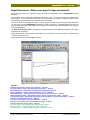
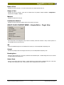
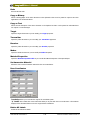
Target Documents - Define your target's shape and material.
Target Documents help you to construct, import and insert real-world targets into the Imagine3D Simulation
document.
Only one target can be stored inside a Simulation document at a time. You can create targets by combining many
parts together. If your inspection target is made up of several parts, just import or create them one by one to
form a single target document that is a composite of the various parts.
There is no limit to the complexity of a target. However, keep in mind that the more interfaces and surfaces there
are, the longer it will take Imagine3D to calculate the surface of the target. This delay happens only when the
target is being constructed. Once a simulation is opened, the complexity of your target will have less of an impact
on system performance.
The Material Properties Table is contained in the Target document so that Material Properties for each target
component can be specified.
Target documents can also be saved as a stand-alone file. This allows you to reuse the target on another project
or share it with someone else.
Target documents are given the .trg file extension.
See also:
Simulation Documents – Define your inspection. – Page 22
Probe Documents – Define your transmitter and receiver. – Page 24
Modes Documents – Define the sound modes to be displayed. – Page 25
Simple (2D) Editor – Probes, modes and raytracing view. – Page 26
B-scan Documents – A plot of all arriving echoes over a scanned distance. – Page 28
Material Properties Table – Edit material velocity, density and attenuation values. – Page 29
Cross-Section Editor – Defines 2D profiles that can be extruded or revolved into 3D solids. – Page 30
How Do I Create New Documents? – Page 35
How Do I Create targets using only Imagine3D? – Page 35
How Do I Create targets from imported CAD drawings? – Page 36
How Do I Adjust the viewing angle? – Page 43
See demo movie – Assembling targets from primitive shapes
See demo movie – Creating Targets from DXF or SAT files
See demo movie – Creating targets using the cross-section editor
Ultrasonic Simulation Software Version 2.5
23
UTEX Scientific Instruments Inc.
Imagine3D User’s Manual
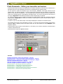
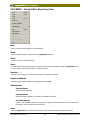
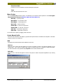
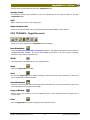
Probe Documents – Define your transmitter and receiver.
Probe documents help you specify the characteristics of ultrasonic transducers so that they can be inserted into a
Simulation document. Both transmitters and receivers are specified using the same document.
You are required to provide the transducer type, center frequency, bandwidth, focal length, element size and
element shape. For raytracing purposes, you need to specify the sound wave type, the number of rays and their
pattern on the surface of the transducer. You can specify that an immersion transducer should be locked to the
surface of the inspected part at a given distance and incident angle. As you move the probe over the surface of
the target, Imagine3D will automatically maintain the offset and angle that you specified.
For contact transducers, you are required to also specify the wedge material, wedge size, inspection angle and
target material. Imagine3D will calculate the transducer’s incident angle so that the desired inspection angle in
the target is achieved.
In Version 2.5 you can now edit the shape of the wedge and display the transducer’s sound field in water.
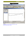
The RF Beam Cross-section can be calculated for the probe. You can also open and save RF Beam Cross-Sections
(extension .sdt) for different probes and compare them with real data collected by using Winspect data
acquisition software.
Probe documents can be saved as a stand-alone file. This allows you to reuse the transducer on another project
or share it with someone else.
Probe documents are given the .prb file extension.
See also:
Simulation Documents – Define your inspection. – Page 22
Target Documents – Define your target’s shape and material. – Page 23
Modes Documents – Define the sound modes to be displayed. – Page 25
How Do I Create New Documents? – Page 35
How Do I Configure an Immersion Transducer? – Page 39
How Do I Configure a Contact Transducer? – Page 39
See demo movie – Switching to pitch-catch operation
See demo movie – Configuring an immersion transducer
See demo movie – Configuring a contact transducer
See demo movie – Viewing the beam cross-section of a transducer
See demo movie – Grouping and ungrouping objects
UTEX Scientific Instruments Inc.
24
Ultrasonic Simulation Software Version 2.5
Imagine3D User’s Manual
.
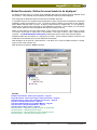
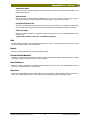
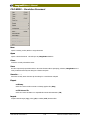
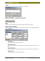
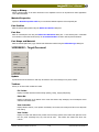
Modes Documents - Define the sound modes to be displayed.
The Modes document helps you to select which longitudinal and shear wave modes should be displayed during
the simulation. It also describes which transmitted and reflected wavefronts should be displayed.
Once configured, the Modes document is inserted into the Simulation document.
In the Modes document, the requested modes (longitudinal or shear) along the entire sound path are represented
graphically, just like the branches on a tree. You have the option of starting a new branch at each interface,
where different materials come in contact. By placing unique branches on separate tabs, it is now possible to
simulate just one branch of the sound path or any combination of branches. As an example, you can separate
corner reflector signals from back-wall multiples that might be cluttering the A-scan.
Modes are easily added by using the modes buttons or right clicking on a mode branch. Each branch, or portion
of a branch, can be given a unique color or line thickness. This makes it easier to spot a particular mode
conversion. The Modes document context menu provides quick access to most modes document options.
Predefined modes allow the selection of a standard set of modes. Corner and direct reflection tools mirror the
modes back to the transducer once you have defined the forward path.
Mode Properties can be saved as a stand-alone file. This allows you to reuse the Modes document on another
project or share it with someone else.
Mode documents are given the .mds file extension.
See also:
Simulation Documents – Define your inspection. – Page 22
Target Documents – Define your target’s shape and material. – Page 23
Probe Documents – Define your transmitter and receiver. – Page 24
How Do I Create New Documents? – Page 35
How Do I Enable Desired Long and Shear Modes? – Page 40
How Do I Select a Sound Display Mode? – Page 41
How Do I Define a Ray’s Color? – Page 42
See demo movie – Organizing groups of modes on subset tabs
See demo movie – Simulating critical angles
See demo movie – Advanced features of the modes document
See demo movie – Selecting which modes to show
Ultrasonic Simulation Software Version 2.5
25
UTEX Scientific Instruments Inc.
Imagine3D User’s Manual
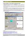
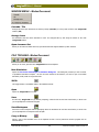
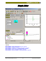
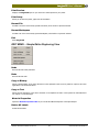
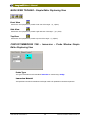
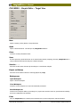
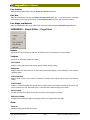
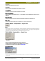
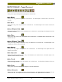
Simple (2D) Editor– Probes, Modes and Raytracing View
The Simple View Editor provides the main elements of Imagine 3D limited to a simpler x-y plane case. The
simple editor reduces some of the flexibility of the main Imagine3D editor in return for a simplified interface.
This gives clarity for novice users.
The Simulation document retains changes made in either mode. Settings for the Simulation document are not lost
when you switch between editors – the inspection remains the same. The difference between two identical
Simulation documents, one in Full Edit mode and the other in Simple Edit mode is what you are allowed to change
while using each editor.
To use the 2D editor, you can create a new default simulation and choose the Simple Editor or you can switch
from a 3D simulation to the simple editor using the Switch 2D /3D button on the Main toolbar. The simple
editor has 4 windows, A-Scan view, Raytracing view, edit Modes and edit Probe contained in the one window.
The Modes and Probe windows can be hidden using the hide and show buttons on the View toolbar.
Essential tools are available in the Simple editor while more advanced functionality is hidden. For example, in the
simple editor different mode subsets are not shown. Only the first subset of modes available in the full editor is
used in the simplified interface.
See Also:
Simulation Documents – Define your inspection. – Page 22
Target Documents – Define your target’s shape and material. – Page 23
Probe Documents – Define your transmitter and receiver. – Page 24
Modes Documents – Define the sound modes to be displayed. – Page 25
Simple (2D) Editor – Target View. – Page 27
Material Properties Table – Edit material velocity, density and attenuation values. – Page 29
UTEX Scientific Instruments Inc.
26
Ultrasonic Simulation Software Version 2.5
Imagine3D User’s Manual
.
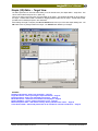
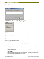
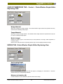
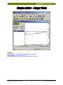
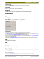
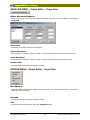
Simple (2D) Editor – Target View
The Edit Target button on the View toolbar takes you to the second screen, The Simple Editor - Target View. This
can be used to edit the target in the x-y plane only.
There is an option in the Tools menu to set the depth of the target. This will affect the depth of all the parts in
the target. A limited Parts toolbar is available for dragging primitive shapes into the target. The Edit Parts toolbar
provides tools for defining the parts in two dimensions.
When editing the target is complete, the OK and Cancel buttons return you to the main simple editing view. The
OK button saves any changes made to the target. The Cancel button discards your changes.
See Also:
Simulation Documents – Define your inspection. – Page 22
Target Documents – Define your target’s shape and material. – Page 23
Probe Documents – Define your transmitter and receiver. – Page 24
Modes Documents – Define the sound modes to be displayed. – Page 25
Simple (2D) Editor – Probes, modes and raytracing view. – Page 26
Material Properties Table – Edit material velocity, density and attenuation values. – Page 29
Cross-Section Editor – Defines 2D profiles that can be extruded or revolved into 3D solids. – Page 30
Ultrasonic Simulation Software Version 2.5
27
UTEX Scientific Instruments Inc.
Imagine3D User’s Manual
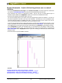
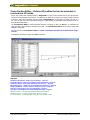
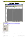
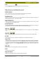
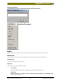
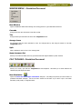
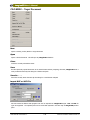
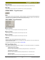
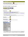
B-scan Documents - A plot of all arriving echoes over a scanned
distance.
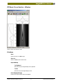
B-scans plot scan distance on the target versus all echo arrival times. B-scan documents are created when
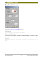
you select the Tools-Generate B-scan menu item, fill in the requested values and press OK.
B-scan documents only need to be generated as needed. They are only one of several different types of
simulation outputs available from Imagine3D. B-scans are not stored in the Simulation document.
B-scans can be presented in two different ways: color or RF.
The color B-scan display shows you the times of the various signals arriving back at the transducer. The colors on
the B-scan correspond to the colors of the rays in the simulation. This allows you to sort out different modeconverted signals that might be overlapping each other. By moving the cursor over the surface of the color Bscan, you can directly measure the arrival times of the echoes using your mouse.
To see what the simulated ultrasonic signals really look like, just switch the B-scan display into RF mode. In this
mode, it is possible to see all of the collected A-scans that make up the RF B-scan. You can also save RF Bscans (.sdt extension) and compare them with real collected data by using Winspect data acquisition software.
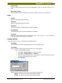
So that Imagine3D can perform the simulated B-scan, you are asked for the scan distance, number of points,
time range and scan direction values. The B-scan always starts at the current probe position. By pressing the
Show Probe Path button, Imagine3D will draw a green line showing you where the probe will be moved
during the B-scan.
B-scan documents are given the .bsn file extension.
See also:
Simulation Documents – Define your inspection. – Page 22
Target Documents – Define your target’s shape and material. – Page 23
Probe Documents – Define your transmitter and receiver. – Page 24
Modes Documents – Define the sound modes to be displayed. – Page 25
UTEX Scientific Instruments Inc.
28
Ultrasonic Simulation Software Version 2.5
Imagine3D User’s Manual
.
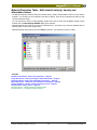
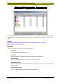
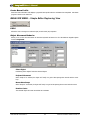
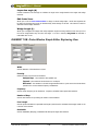
Material Properties Table - Edit material velocity, density and
attenuation values.
The Material Properties document stores the acoustic velocity, density and attenuation values for many common
materials. You can add your own materials to the table, if desired. These are the materials from which you may
construct inspection targets.
You can also pick the colors you want displayed, anytime that a long or shear wave propagates through a given
material when the show Rays by Medium display type is selected.
Material Properties documents can be saved as a stand-alone file. This allows you to reuse the materials table on
another project or share it with someone else.
Material Properties documents are given the .med file extension. The extension is short for "media".
See also:
Simulation Documents – Define your inspection. – Page 22
Target Documents – Define your target’s shape and material. – Page 23
Probe Documents – Define your transmitter and receiver. – Page 24
Modes Documents – Define the sound modes to be displayed. – Page 25
Simple (2D) Editor – Probes, modes and raytracing view. – Page 26
How Do I Define a Ray’s Color? – Page 42
See demo movie – Working with the materials table
See demo movie – Changing a target's material
Ultrasonic Simulation Software Version 2.5
29
UTEX Scientific Instruments Inc.
Imagine3D User’s Manual
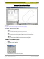
Cross-Section Editor – Defines 2D profiles that can be extruded or
revolved into 3D solids.
One of your options when creating a target in Imagine3D is to draw a cross-sectional view of your part and then
extrude it into a 3D length of your choice. You also have the option of revolving it into a solid, through a number
of degrees. Once the cross-section has been drawn, Imagine3D gives you the option of saving your work to a
file. You can then reuse the cross-section elsewhere. Cross-sections are particularly useful for objects such as
train rails and turbine disks.
The Cross-Section Editor is used temporarily whenever you import or edit a 2D .dxf file. It represents the
stage just before it is extruded or revolved into a solid. The Cross-Section Editor can be used to make small
changes in the profiles.
You can also use the Cross-Section Editor to Create a Revolved or Extruded Cross-Section Part using a
text file.
Cross-section documents are given the .xsn file extension.
See also:
Simulation Documents – Define your inspection. – Page 22
Target Documents – Define your target’s shape and material. – Page 23
Probe Documents – Define your transmitter and receiver. – Page 24
Modes Documents – Define the sound modes to be displayed. – Page 25
Simple (2D) Editor – Probes, modes and raytracing view. – Page 26
How Do I Create targets using only Imagine3D? – Page 35
How Do I Create targets from imported CAD drawings? – Page 36
See demo movie – Assembling targets from primitive shapes
See demo movie – Creating targets from .dxf and .sat files
See demo movie – Creating targets using the cross section editor
UTEX Scientific Instruments Inc.
30
Ultrasonic Simulation Software Version 2.5
Imagine3D User’s Manual
.
Workspace Folders -- save everything so that you can continue your
work later.
Workspace folders are created when you ask Imagine3D to save your work to a workspace. The information
that Imagine3D saves in the new folder includes your current screen configuration and any documents that are
open at the time of saving. You do not need to use workspaces at all if you do not care about saving the other
open documents.
The first time that a new workspace is saved,a new Workspace folder and Workspace file is created—both share
the same root name. All target, probe and mode documents that were open at the time of saving are also saved
in this new folder. RF B-scans and RF Beam Cross-Sections are not saved in workspaces. By recalling a
workspace, Imagine3D re-opens the document files and reconfigures the screen, as it was when you last saved
the workspace.
You can share workspaces with someone else, however, it is important that you provide them with all of the files
that are in the workspace directory. There will always be a minimum of two files: a Workspace file and a
Simulation document.
Workspace files are given the .prj file extension. This stands for Project.
Ultrasonic Simulation Software Version 2.5
31
UTEX Scientific Instruments Inc.
Imagine3D Users Manual
.
How Do I ?
Ultrasonic Simulation Software
33
UTEX Scientific Instruments Inc.
Imagine3D User’s Manual
.
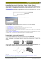
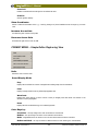
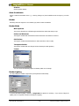
Create New Documents (Simulation, Target, Probes, Modes)
There are two main methods used to create new documents. The first is to create a default Simulation document
and then edit each of the individual parts (Target, Modes etc.) of that document. The second is to create each
specific document type individually and then insert each into the Main simulation document.
The New Simulation button creates a default Simulation document that contains default Target, Probe and
Modes. The default target is a calibration step block.
The File – New menu item provides a selection of document types to create.
Target, Probe, Modes, Simulation and Simple Simulation documents can all be created individually.
A new Target document is created completely empty.
A new Probe document contains default values for the probe, which need to be edited.
A new Modes document contains a single mode from the probe.
A new Simulation document contains the default documents for each case above, a default probe, no target and
only the first mode from the Probe.
The new Simulation-Simple document is a Simulation document that starts in the Simple Editor and contains
a step block target, an immersion probe with the modes setup for normal beam inspection.
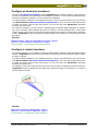
Create targets using only Imagine3D
If you do not have CAD drawings, your target can be constructed entirely within Imagine3D.
You can assemble targets from a range of primitive shapes such as blocks, rods, tubes, spheres, cones and crosssections. These shapes can be embedded, attached or removed from each other to form a combined solid
geometry.
You can also draw cross-section details using the built-in cross-section editor that allows you to specify line, arc,
or spline segments. These cross-sections can then be extruded or revolved into 3D solids.
See also:
How Do I Create a Revolved or Extruded Cross-Section Part using a text file of points? – Page 37
See demo movie – Creating targets using the cross-section editor
Ultrasonic Simulation Software Version 2.5
35
UTEX Scientific Instruments Inc.
Imagine3D User’s Manual
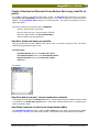
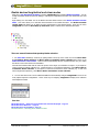
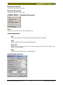
Create targets from imported CAD drawings
Imagine3D can import CAD drawings in .sat and .dxf file formats. Files can be imported by using the File –
Import DXF or SAT menu item or by selecting the .SAT or .DXF checkboxes in the Define Part Type dialog
box when a new part is added.
If you have 3D CAD drawings, your drawing is imported as 3D solids from either .dxf or .sat files. 3D shapes
contained in .dxf files must be drawn as 3D faces or 3D volumes enclosed by a mesh. 3D solids contained in .sat
files are already fully constructed and are usually imported without any problems.
If you have 2D cross-section drawings, your .dxf files are imported and extruded or revolved into 3D solids.
Cross-sections in .dxf files must be drawn as a closed polyline. See Setup a DXF file for Import into
Imagine3D (below).
In all cases, the .dxf file should contain only one object at a time.
.dxf files are generated by popular packages such as AutoCAD and TurboCad as well as by many vector-based
drawing packages such as Corel Draw and Micrografix. Most CAD packages have some form of .dxf exporting
capability.
.sat files are generated by AutoCAD and TurboCad or any other vendor that has licensed the ACIS solid
modeling engine from Spatial Technologies.
See demo movie – Creating targets from .dxf and .sat files
Setup a DXF file for Import into Imagine3D
There are a few simple rules that must be followed when importing .dxf files:
1) Importing 2D .dxf drawings
Imagine3D will import any closed 2D-polyline shape and extrude it or revolve it into a solid.
Rules:
•
Only one object should be in the .dxf drawing at a time.
•
There should be no dimensions, dimension lines or annotations in the drawing.
•
The object needs to be drawn with a polyline that has been closed.
•
Export the DXF in AutoCAD version 12 or 13 format. Newer DXF versions contain lots of extras that get in
the way.
Open polylines and more than one object in the drawing will return an "unknown file format" error. The part will
not be imported.
Use the PEDIT command in AutoCAD to confirm that the polyline is closed. If it is not closed, PEDIT can be used
to close it.
Here is a simple hint for creating .dxf files from AutoCAD drawings that contain many objects. Erase all of the
objects in the drawing except for the one that you wish to export to .DXF. Export the object. Select the Undo
function until the original drawing is restored. Repeat the above procedure for each object that you would like to
export.
Import each exported .dxf file one by one into Imagine3D and assign it the correct Material Properties.
2) Importing 3D .DXF drawings
Imagine3D will import any number of fully enclosed 3D objects.
Any object drawn with 3D surfaces that completely encloses a volume will correctly import into Imagine3D.
UTEX Scientific Instruments Inc.
36
Ultrasonic Simulation Software Version 2.5
Imagine3D User’s Manual
.
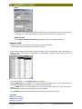
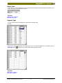
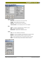
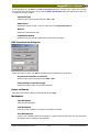
Create a Revolved or Extruded Cross-Section Part using a text file of
points.
It is possible to define a cross-section profile using a .txt file. The File-Open menu item allows you to read in
both .txt and .xsn (Imagine3D Cross-section document) files. The editor can import a list of the points from a
.txt file. The Cross-Section Editor uses lines to connect each point. The profile can be edited to use arcs or
splines after import.
Four Steps to making a Cross-Section Profile in Imagine3D
Step One: Create and save your text file.
Step Two: Add a new part – choose revolved or extruded.
Step Three: Open text file in the Cross-Section Editor.
Step Four: Define other part parameters.
Step One: Create and save your text file.
Using any program that will create a .txt file, enter a list of points. The format is one point per line. The x and y
values must be separated by a space or tab.
Text File Format
First Point X Value<space or tab>First Point Y Value
Second Point X Value<space or tab>Second Point Y Value
Next Point X Value<space or tab>Next Point Y Value
And so on . . .
For example:
Step Two: Add a new part – choose revolved or extruded.
In the Target Document select the Add New Part button. The part material and part combination method needs
to be selected in the Define Part Type dialog box. Select either “Revolved Cross-section” or “Extruded Crosssection” as the part’s shape.
Step Three: Open the text file in the Cross-Section Editor
The Cross-Section Editor will appear. Select the File – Open menu item. Select “Text Cross-Section (*.txt)”
as the File type. Choose to open your text file of points. The new points of the profile will appear in the Editor.
Ultrasonic Simulation Software Version 2.5
37
UTEX Scientific Instruments Inc.
Imagine3D User’s Manual
Step Four: Define other part parameters
The extrusion length or the revolution angle as well as the part’s position in the Define Part Position dialog box
need to be specified before you can view the final product.
This is the completed revolved cross-section in the target editor.
Select Pulse Echo or Pitch Catch
Imagine3D supports both Pulse Echo and Pitch Catch ultrasonic methods. The default mode is Pulse Echo.
Pitch Catch (often called Dual Mode) simply means that you are using two transducers, one for transmitting and
one for receiving. Methods that use a Pitch Catch arrangement are TTU (Through Transmission Ultrasonics),
dual-element transducers and Tandem transducers (same-side inspections using two transducers).
To change from Pulse Echo to Pitch Catch, click the right mouse button in any 3D pane and select PE/PC.
If you have selected Pitch Catch and can see only one transducer on the screen, click the Fit All Views toolbar
button. The receiver should now be visible as well. Move the receiver closer to the target and click Fit All
Views, again. This will restore the display so that you can more easily configure the inspection. Whenever you
lose sight of either transducer, click the Fit All Views button.
See demo movie – Switching to Pitch Catch operation
UTEX Scientific Instruments Inc.
38
Ultrasonic Simulation Software Version 2.5
Imagine3D User’s Manual
.
Configure an immersion transducer
Each time a new Simulation document is opened Imagine3D inserts a default transducer. This transducer is
a 5 MHz, 10mm diameter, 70mm spherically focused immersion transducer. You can modify this default by simply
entering the values that correspond to your own transducer’s specifications.
To modify the default transducer in any Simulation document, click the right mouse button in the 3D View and
select Edit Transmitter (Simulation Document 3D Context Menu). If you are in Pitch Catch mode and wish
to modify the receiver, click the right mouse button in the 3D View and select Edit Receiver (Simulation
Document 3D Context Menu).
For immersion transducers, you may choose to explicitly specify the Incident Angle and Distance to Interface.
This “lock to Interface” feature simulates the action of a squirter or contour-following scanner. When moved
using the mouse or the cursor keys, the transducer will stay aligned to the surface at a fixed distance, fixed angle
or both. Imagine3D will resist any attempt to change the angle of the transducer or to vary the offset from the
part surface.
See also:
Probe Documents -- define your transmitter and receiver – Page 24
Reference – Probe Document - Immersion tab – Page 79
See demo movie – Configuring an immersion transducer
Configure a contact transducer
For contact transducers, you are required to specify the wedge material, wedge size, inspection angle and target
material. Imagine3D will calculate and set the transducer’s incident angle so that the desired inspection angle in
the target is achieved.
To modify the default transducer in any Simulation document, click the right mouse button in the 3D View and
select Edit Transmitter (Simulation Document 3D Context Menu). If you are in Pitch Catch mode and wish
to modify the receiver, click the right mouse button in the 3D View and select Edit Receiver (Simulation
Document 3D Context Menu).
The transducer, when moved using the mouse or the cursor keys, will stay in contact with the surface of the part.
Imagine3D will resist any attempt that you might make to change the angle of the transducer or to remove it
from the surface of the part.
See Also:
What's New in Version 2.5 - Wedge Editor – Page 3
Reference – Probe Document - Wedge tab – Page 79
See demo movie – Configuring a contact transducer
Ultrasonic Simulation Software Version 2.5
39
UTEX Scientific Instruments Inc.
Imagine3D User’s Manual
Enable desired longitudinal and shear modes
Each time a new Simulation document is opened, Imagine3D inserts a default Modes Document. You can
modify this default Modes document by adding or removing the longitudinal and shear wave modes that you want
to see.
Right clicking over the Modes Tree in the Modes Document allows access to the Modes Document Context
Menu. This menu allows you to add and remove branches in the modes document. The Modes Document
context menu also allows you to define the color and thickness of the selected modes. These are the colors
Imagine3D uses when the Show Rays by Generation option is selected in the Simulation document.
There are several features that speed up Modes selection.
1. For Pulse Echo simulations, a fast way of getting modes to show up on the A-scan is to use the Mirror Back
to Transmitter–Direct reflection and Mirror Back to Transmitter–Corner reflection menu items on the
Modes Document Context Menu. These functions automatically add the required branches into your modes
document to return the sound to the transmitter.
First add the forward modes that will reach the portion of the target you would like to inspect. If you expect to
receive sound from a direct reflection (e.g. a back wall echo in a normal beam inspection), select Mirror Back to
Transmitter–Direct reflection. If you expect to receive the sound from a corner reflection (e.g. a crack root
with an angle beam inspection), select Mirror Back to Transmitter–Corner reflection.
2. You can also select from a list of Predefined Modes that automatically configure Imagine3D for some of the
most popular inspection configurations. This is a fast way of configuring Imagine3D to display corner reflectors
and multiple back walls.
See also:
Modes Documents -- define the sound modes that should be displayed – Page 25
Modes Document Reference – Page 65
Modes Document Context Menu – Page 70
See demo movie – Selecting which modes to show
UTEX Scientific Instruments Inc.
40
Ultrasonic Simulation Software Version 2.5
Imagine3D User’s Manual
.
Select a sound display mode (rays, wavefronts, beam or pulse)
Imagine3D can display sound fields in several different ways.
Rays are the default presentation because they are intuitive and robust. Rays simply represent the sound field as
a series of straight lines that leave the probe face, then transmit or reflect at the interface between dissimilar
materials.
Selecting Wavefronts shows the sound field as a series of short curved (or straight) lines that follow one another
in the direction of the sound propagation. The spacing between the waves increases or decreases in relation to
the velocity of the sound in each medium. This presentation can be quite informative. However, if the sound
scatters off corners, it may appear cluttered as the wavefront begins to spread. To reduce this clutter, restrict the
number of generations presented when using the wavefront display.
The Beam Profile shows the sound field as a rendered, grayscale image showing the transducer focus, side
lobes and near-field interference patterns. Ultrasonic beams are calculated using a summation of Gaussian
solutions to the parabolic wave equation.
The Pulse display shows a single wavefront at any selected time. A series of pulses can be animated to show a
moving wavefront through the target (select Tools-Show Pulse Animation). The width of the wavefront, as
plotted, represents the actual physical pulse-width in the medium. Therefore, faster velocity materials will exhibit
a wider pulse-width
Rays
Wavefronts
Beam
Pulse
Imagine3D allows the display mode to be defined in a number of ways. The most direct is to select the display
mode using the Format – Sound Display Mode menu item. Alternately, the display mode can be defined in the
Sound Display Properties dialog box (Format – Sound Display Properties menu item).
See demo movie - Switching between sound display modes
Ultrasonic Simulation Software Version 2.5
41
UTEX Scientific Instruments Inc.
Imagine3D User’s Manual
Define a ray’s color (used to highlight the mode type, medium type or
generation)
To change how colors are used when displaying rays, select Format – Ray Color in the Simulation document.
Your choices are:
Selection
What the Ray Colors Indicate
By Generation
The rays change color whenever an interface
between two materials is encountered.
By Medium
The rays are assigned colors based on the target
material.
By Mode
Longitudinal waves are shown in one color and
shear waves are shown in another.
By Medium and Mode
Longitudinal waves and shear waves are shown as
color pairs which are different for each target
material.
You can set how the sound fields change color based on whether a mode conversion occurs, a new medium is
entered or a new wave is generated. The default color-coded display setting is by generation because it
guarantees a new color each time the sound leaves an interface.
The colors used when the rays are displayed by Generation are set in the Modes document. The colors used
when the rays are displayed by Medium or by Mode can be set in the Material Properties Table.
See Also:
Modes Documents– Define the sound modes to be displayed – Page 25
Material Properties Table – Edit material velocity, density and attenuation values. – Page 29
Move the probe around the target
To move the probe, you must first select the probe by double-clicking on it or by pressing TAB until the probe is
selected. Selected objects are drawn in bold lines and show black dragging handles.
Imagine3D uses three different cursor types to indicate what motion will occur when you hold the left mouse
button down to drag the selected object.
Move Cursor
UTEX Scientific Instruments Inc.
Spin Cursor
42
Rotate Cursor
Ultrasonic Simulation Software Version 2.5
Imagine3D User’s Manual
.
To move the probe with the mouse, place the cursor over the probe. When the cursor changes into the Move
Cursor, press and hold the Left mouse button to drag the probe around your simulation.
When you place the cursor over the right drag handle, the Spin Cursor will appear. Holding the left-mouse
button while the Spin Cursor is showing will turn the probe around itself, the probe direction will change but not
it’s position.
When you place the cursor over the left drag handle, the Rotate Cursor will appear. Holding the left-mouse
button while the Rotate Cursor is showing will rotate the probe about the probe’s movement origin. As the
probe is dragged, it will change both in direction and position.
The movement origin for any dragable object can be set using the Set Dragable Object Properties dialog box
(Behavior - Object Movement Behavior menu item).
An easy way to move the probe left or right and up or down is with the arrow keys. You can spin the probe
by holding down the Shift key while pressing the arrow keys. To rotate the probe hold the Ctrl key while you
press the arrow keys.
See also:
Simulation Documents – Define your inspection – Page 22
Adjust the viewing angle
You can tilt, rotate and spin any Simulation view so that it can be seen from a different viewing angle. You do
this by clicking on the arrow buttons in the View Controlbar at the bottom of the main Imagine3D window.
Pressing the T, R or S keys will also tilt, rotate and spin the view. Holding down the Alt key at the same time
reverses the direction of motion.
See also:
Simulation Documents – Define your inspection – Page 22
Reference – Simulation Document - Rotation Step Size – Page 123
Select the A-scan view
The A-scan view shows a simulated RF or rectified signal as you might expect to see on the screen of a flaw
detector. The A-scan is constructed from the sum of the amplitudes of the received rays convolved with the
probe’s response. All phase and amplitude information is maintained based on the transmission and reflection
coefficients at each interface.
How to select the A-scan view
1.
It is often easiest to split the Simulation view into more than one pane. By dragging a splitter control (outer
ends of the scroll bars) into the simulation, you will split the views. This will allow you to see a 3D view and
the A-scan view at the same time.
2.
It is a good idea to select one of the least used 3D panes to display the A-scan. Sometimes this might be the
top view or the side view of the inspected part.
3.
To display the A-scan view, first click inside the desired pane, then click the right mouse button and select
View Type – A-scan.
See Also:
A-scan Context Menu – Page 138
See demo movie - Viewing A-scans and arrival times
Ultrasonic Simulation Software Version 2.5
43
UTEX Scientific Instruments Inc.
Imagine3D User’s Manual
Select the Text description view
To select the Text description view:
1.
It is often easiest to first split the Simulation view into more than one pane. By dragging a splitter control
(outer ends of the scroll bars) into the simulation, you will split the views. This will allow you to see the 3D
view and the Text view side by side.
2.
It is a good idea to select one of the least used 3D panes for display of the Text view. Sometimes this
might be the top view or the side view of the part.
3.
To show the Text view, first click inside the desired pane, then click the right mouse button and select View
Type – Text.
The Text view uses three sections to describe the inspection:
1. Center Ray Statistics (only the physically possible rays)
Each time the ray encounters an interface, a line of text is added to the listing in the Center Ray Statistics section.
This text describes the current material, mode of propagation, transit time, distance traveled, angle, ray starting
point and ray direction.
The following is a sample of the text:
2. A-scan Arrivals (only the rays reaching the receiver)
Whenever a ray finally hits the surface of the receiver two lines of text are added to the listing in the A-scan
Arrivals section.
The following is a sample of the text:
3. Modes (requested by user)
This section contains a description based on the current Modes document.
The following is a sample:
See also:
Simulation Documents – Define your inspection – Page 22
See demo movie - Using the text view
See demo movie - Copying to the clipboard
UTEX Scientific Instruments Inc.
44
Ultrasonic Simulation Software Version 2.5
Imagine3D User’s Manual
.
Produce a printed report
Imagine3D provides a powerful print preview feature that displays exactly how the printout will appear.
There are three types of annotation text that may be added to printed reports:
You can add a 3D-text label that tilts and rotates relative to viewing angle changes. This text is ideal for labeling
planes such as the front view because the text will appear to be lying flat on the front view surface when viewed
from a different angle.
You can also add a 3D-text title that does not tilt or rotate relative to viewing angle changes. This text is ideal for
object identification purposes because it always faces you regardless of the viewing angle.
A printer comment can be added so that the text entered will appear on printed reports just below the header
information. This text is ideal for adding administrative information such as “prepared by” or other project
information.
See also:
Simulation Documents – Define your inspection – Page 22
See demo movie - Using the text view
See demo movie - Copying to the clipboard
See demo movie - Previewing a printed report
Ultrasonic Simulation Software Version 2.5
45
UTEX Scientific Instruments Inc.
Imagine3D Users Manual
.
Reference
Ultrasonic Simulation Software
47
UTEX Scientific Instruments Inc.
Imagine3D User’s Manual
.
B-scan Documents
See also:
B-scan Documents – A plot of all arriving echoes over a scanned distance. – Page 28
FILE MENU-B-scan Document
Ultrasonic Simulation Software Version 2.5
49
UTEX Scientific Instruments Inc.
Imagine3D User’s Manual
New
Opens a new Ray, Probes, Modes or Target document.
Open
Opens or finds a document. This will open any Imagine3D related file.
Close
Closes the currently selected document.
Save
Re-saves a previously opened document to the same filename without prompting, otherwise, Imagine3D saves a
newly created document by first asking for a filename and path.
Save As
Saves the currently active document by first asking for a new filename and path.
Open RF B-scan
Allows you to open any saved RF scan files (.sdt).
Workspaces
Open Workspace - opens or finds a Workspace.
Close Workspace - closes the current workspace so it cannot be accidentally overwritten.
Save Workspace As - creates a new workspace folder by first asking for a project name and then
saves any open documents including the screen configuration into that folder.
Print Preview
Displays an Imagine3D report on your screen as it will be printed on your printer.
Print Setup
Allows you to select the printer, paper size and orientation.
Recent File
Provides a list of the most recently opened Documents, which will be re-opened if selected.
Recent Workspace
Provides a list of the most recently opened Workspaces which will be re-opened if selected.
Exit
Exits Imagine3D.
UTEX Scientific Instruments Inc.
50
Ultrasonic Simulation Software Version 2.5
Imagine3D User’s Manual
.
VIEW MENU – B-scan Document
Toolbars
Allows the user to show and hide each of the toolbars for the B-scan Document.
File Toolbar
Displays a toolbar with buttons that manage opening, saving, copying, printing.
Status Bar
Displays a status bar at the bottom of the screen that shows: Help messages, current Workspace name
and beam calculation status.
RF B-scan
Displays the RF B-scan for this document.
WINDOW MENU – B-scan Document
New Window
Opens an additional child window allowing more viewing panes for a given Simulation document.
Cascade / Tile
Arranges all of the open documents so that they overlap (cascade) or so they resize to fill the main Imagine3D
window (Tile).
Arrange Icons
All documents that have been minimized to icons are arranged side by side along the bottom of the main
Imagine3D window.
Open document list
Allows you to locate and make active any open documents that might be hidden by other windows.
Ultrasonic Simulation Software Version 2.5
51
UTEX Scientific Instruments Inc.
Imagine3D User’s Manual
RF BB-scan Window
Shows data in RF format.
See also:
B-scan Documents – A plot of all arriving echoes over a scanned distance. – Page 28
File menu – RF B-scan
Save
Saves the scan to an .sdt file type so that it can be reloaded later or viewed using Winspect.
UTEX Scientific Instruments Inc.
52
Ultrasonic Simulation Software Version 2.5
Imagine3D User’s Manual
.
Save As …
Saves an .sdt file with a chosen name.
Export Bitmap
To Clipboard - Places the color plot image bitmap on the clipboard.
To File - Writes the color plot image bitmap to a file.
Print Displayed Image
Prints the color plot using the chosen Print Options.
Print Options
Selects whether Print Header, Axis Summary Information, Scale, Horizontal and Vertical Cross-sections will be
printed.
Edit Comment
Allows you to add a comment that will be saved with the image and will appear on printouts.
Display Header
Displays information about this image.
View menu – RF B-scan
Zoom In
Drag mouse over color plot to select the region to be enlarged.
Zoom Out
Fits the whole scan to the view window.
Pixel per Point
Displays the image using one screen pixel for each data point.
1:1 Aspect Ratio
Makes the horizontal and vertical axes the same scale.
Lock Aspect Ratio
Maintain the current ratio of the scales for the horizontal and vertical axes while zooming or sizing.
Ultrasonic Simulation Software Version 2.5
53
UTEX Scientific Instruments Inc.
Imagine3D User’s Manual
RF B-scan Toolbar Buttons
Save
Saves the scan to an .sdt file type.
Print
Prints the color plot using the chosen Print Options.
Zoom In
Drag mouse over color plot to select the region to be viewed.
Zoom Out
Fits the whole scan to the view window.
1:1 Ratio
Makes the horizontal and vertical axes the same scale.
Color Palette
Displays a color selection editor that allows you to assign colors to amplitudes.
Horizontal X-sec
Displays a horizontal cross-section above the color plot.
amplitude cross-section at this point.
Click on a location in the color plot to display the
Vertical X-sec
Displays a vertical cross-section to the left of the color plot. Click on a location in the color plot to display the
amplitude cross-section at this point.
UTEX Scientific Instruments Inc.
54
Ultrasonic Simulation Software Version 2.5
Imagine3D User’s Manual
.
CrossCross-Section Editor
See also:
Target Documents – Define your target’s shape and material – Page 23
File Menu – Cross-Section Editor
Open
Opens a cross-section editor file (.xsn) or text file (.txt) from disk.
Save
Saves a previously saved cross-section editor file (.xsn) to disk using its original filename.
Save As
Saves a cross-section editor file (.xsn) to disk using a filename you have chosen.
Edit Menu – Cross-Section Editor
Undo
Reverses the last action performed.
Tolerance
Defines the accuracy to which vertices will be placed.
Ultrasonic Simulation Software Version 2.5
55
UTEX Scientific Instruments Inc.
Imagine3D User’s Manual
Units
Use this tool when importing 2D .dxf files that have been drawn in different units than your current target.
For example, a 2D .dxf file that was drawn in inches could be converted into mm using this tool.
Define Co-ords
Uses the Define translation and rotation dialog box to define the coordinates of the part.
Segment table
This is a list of all of the vertices and the segments that connect them together.
You can change and insert coordinates and connecting line types.
Entire drawing segments can be selected, inserted or deleted. Click on the left-margin (Vertex pair number) to
select a segment. Each segment is represented by a "vertex pair”. Example: the first vertex pair is shown
highlighted (row 1).
The vertex pair values: X, Y and Segment type can be changed.
Pressing Enter updates the properties of the vertex referenced in the Vertex field. You can create almost any
shape merely by repeatedly changing the X,Y coordinates and pressing enter.
Pressing Insert creates a new vertex between the previous and currently selected rows. This new vertex can
then be dragged (on the cross-section drawing view) to a new location.
Pressing Delete removes the currently selected vertex from the cross-section drawing area.
See also:
Vertex Pairs – Page 57
Segment Type – Page 57
Define Arc – Page 58
UTEX Scientific Instruments Inc.
56
Ultrasonic Simulation Software Version 2.5
Imagine3D User’s Manual
.
Vertex Pairs
Vertex pairs (X, Y) can be added one by one to the cross-section drawing area by entering the coordinates of the
vertex. Use Tab to move between the columns.
See also:
Segment Type – Page 57
Define Arc– Page 58
Segment Type
You can connect vertices with straight lines, splines and arc segment types.
Example:
When an arc has been selected as the segment type, you can set various attributes of the segment using the
Define Arc Button
. Choose the arc’s radius, center and the direction of travel.
See also:
Vertex Pairs – Page 57
Define Arc– Page 58
Ultrasonic Simulation Software Version 2.5
57
UTEX Scientific Instruments Inc.
Imagine3D User’s Manual
Define Arc
Arc Radius
Enter the radius of the segment.
Arc Center
Choose to have the arc center below (Option 1 with a negative Y value), or above the vertices (Option 2
with a positive value). The X value of the center is half of the distance between the two vertices.
Select part of arc to keep
Depending on the arc center, selecting the clockwise or counter-clockwise direction will have different
effects.
Selection of what part of an arc to keep
arrow direction indicates clockwise or counterclockwise
P1
r
r
r
r
P2
P - Vertex point
r - Arc radius
See also:
Vertex Pairs – Page 57
Segment Type – Page 56
UTEX Scientific Instruments Inc.
58
Ultrasonic Simulation Software Version 2.5
Imagine3D User’s Manual
.
Zoom In
Makes the cross-section in the view window appear 20% larger.
Zoom Out
Makes the cross-section in the view window appear 20% smaller.
Fit to Window
Automatically scales the cross-section to fit in the drawing window.
Closed Cross-Section
With Closed Cross-Section checked, a line is used to connect the first point in the cross-section to the last
point, thereby creating a closed polyline. Shapes can only be extruded or revolved once they have been closed.
Extrusion Length
This field only appears for Extruded Cross-Sections. Enter the extrusion length in this field. This is the length the
2D profile will be extended along the z-axis to make the part 3D.
Revolve around y-axis at x=
Only appears for Revolved Cross-Sections. Enter the x value to be revolved about in this field. The Cross-Section
is revolved around a vertical axis at this x value.
Revolution Angle
Only appears for Revolved Cross-Sections. Enter the angle of revolution desired in this field.
Move Viewpoint
Press the arrow buttons to change the viewpoint in the X or Y directions.
Cursor Location Readout
Shows the current position of the cursor.
Ultrasonic Simulation Software Version 2.5
59
UTEX Scientific Instruments Inc.
Imagine3D User’s Manual
.
Material Properties Document
This is a list of materials from which you may construct targets. You may add your own new materials or edit the
existing materials. The main table has a context menu that can be reached by right clicking on a material in the
table.
See also:
Material Properties Table – Edit material velocity, density and attenuation values. – Page 29
Materials Table Context Menu– Page 62
File menu
Allows you to save and recall Material Properties tables from disk.
Open Table
Recalls a Material Properties table from disk.
Save Table
Saves a previously opened Material Properties table to disk using its original name.
Save Table As
Saves a new Material Properties table to disk with a name you have chosen.
Open Default Table
Recalls the default Material Properties table from disk. This table will be used in any new Simulation or
Target document.
Save As Default Table
Saves the currently open Material Properties table as the default table.
Ultrasonic Simulation Software Version 2.5
61
UTEX Scientific Instruments Inc.
Imagine3D User’s Manual
Edit menu
Allows for the creation or editing of materials in a materials properties table.
Add New Material
Adds a new or modified material to the Material Properties Table.
Edit Material
Provides a dialog box where all of the material's properties can be set. This dialog box can be reached by
a right click on the materials table or from the Edit Menu.
Delete Material
Removes a selected material from the open Material Properties table.
Set Default Material
Sets the default materials used when creating new targets and wedges as well as the default immersion
liquid for new Simulations.
Units menu
Sets the length and time units for the velocity and attenuation ratios.
RIGHT CLICK CONTEXT MENU – Materials Table
This context menu was designed for easy access to commonly used menu functions. Many of these options are
also available from the main menu bar.
Add
Adds a new or modified material to the Material Properties Table.
Material Name
Assign a name to your new material or edit an existing name.
Material Type
Specify whether the material is a solid, liquid or gas so that Imagine3D can determine whether to
support certain wave propagation.
Density
Input the density of the material in relation to water. Water’s density is 1.0.
UTEX Scientific Instruments Inc.
62
Ultrasonic Simulation Software Version 2.5
Imagine3D User’s Manual
.
Attenuation Units
Informs you of the units currently being used for attenuation values since the table values depend on the
distance units selected.
Velocity Units
Defines the units for sound velocity as distance (mm, cm, m, inch, or feet) per unit time (ųs, ms, sec).
The velocity values in the table are adjusted making this feature a useful velocity converter.
Longitudinal/Shear Color
The colors for longitudinal and shear waves may be set for each material. It is advisable to select colors
that are similar, such as light and dark green so that materials can be identified regardless of wave type.
Thick/Thin Rays
Allows you to place emphasis on a particular material by making only the rays in that material thicker than
the other rays.
(Active only in Format – Ray Color – By Medium and Mode)
Edit
Provides a dialog box where all of the material's properties can be set. This dialog box can be reached by a right
click on the materials table or from the Edit Menu.
Delete
Removes a selected material from the Material Properties table.
Set as Default Material
Depending on the material’s properties, this sets the current material as the default material used when creating
new targets, wedges or immersion liquids for new Simulations.
Ray Thickness
Allows you to place emphasis on a particular material by making only the rays in that material thicker than the
other rays. The choices are Thick, Thin and Hide.
Ray Color
The colors for longitudinal and shear waves may be set for each material. It is advisable to select colors that are
similar, such as light and dark green so that materials can be identified regardless of propagation type.
Ultrasonic Simulation Software Version 2.5
63
UTEX Scientific Instruments Inc.
Imagine3D User’s Manual
.
Modes Document
See also:
Modes Documents– Define the sound modes to be displayed. – Page 25
Modes Document Context Menu – Page 70
FILE MENU – Modes Document
Ultrasonic Simulation Software Version 2.5
65
UTEX Scientific Instruments Inc.
Imagine3D User’s Manual
New
Opens a new Ray, Probes, Modes or Target document.
Open
Opens or finds a document. This will open any Imagine3D related file.
Close
Closes the currently selected document.
Save
Re-saves a previously opened document to the same filename without prompting, otherwise, Imagine3D saves a
newly created document by first asking for a filename and path.
Save As . . .
Saves the currently active document by first asking for a new filename and path.
Workspaces
Open Workspace
Opens or finds a Workspace.
Close Workspace
Closes the current workspace so it cannot be accidentally overwritten.
Save Workspace As
Creates a new workspace folder by first asking for a project name and then saves any open documents
including the screen configuration into that folder.
Print
Prints an Imagine3D report consisting of the Simulation view (current configuration), date and filename.
Print Preview
Displays an Imagine3D report on your screen as it will be printed on your printer.
Print Setup
Allows you to select the printer, paper size and orientation.
Recent File
Provides a list of the most recently opened Documents, which will be re-opened if selected.
Recent Workspace
Provides a list of the most recently opened Workspaces, which will be re-opened if selected.
Exit
Exits Imagine3D.
UTEX Scientific Instruments Inc.
66
Ultrasonic Simulation Software Version 2.5
Imagine3D User’s Manual
.
EDIT MENU – Modes Document
Copy as Bitmap
Places a bitmap graphic of the active document on the clipboard so that it can be pasted as a picture into other
applications such as Microsoft Word.
Copy as Text
Places the text description of the active document on the clipboard so that it can be pasted as unformatted text
into reports or e-mail messages.
Predefined Modes
Using predefined modes is a quick way of building useful simulations by simply placing standard mode
configurations on individual subset tabs.
Standard Configurations
•
Normal Beam (1 back wall)
•
Normal Beam (2 back walls)
•
Normal Beam (3 back walls)
•
Shear Wave pulse echo
•
Shear Wave pitch catch
VIEW MENU – Modes Document
Toolbars
Allows the user to show and hide each of the toolbars for the Modes Document.
File Toolbar
Displays a toolbar with buttons that manage opening, saving, copying, printing.
Status Bar
Displays a status bar at the bottom of the screen that shows: Help messages, current Workspace name
and beam calculation status.
Zoom Full
Resizes the Modes document so that all the modes are shown.
Ultrasonic Simulation Software Version 2.5
67
UTEX Scientific Instruments Inc.
Imagine3D User’s Manual
WINDOW MENU – Modes Document
Cascade / Tile
Arranges all of the open documents so that they overlap (Cascade) or so they resize to fill the main Imagine3D
window (Tile).
Arrange Icons
All documents that have been minimized to icons are arranged side by side along the bottom of the main
Imagine3D window.
Open document list
Allows you to locate and make active any open documents that might be hidden by other windows.
FILE TOOLBAR– Modes Document
Allows you to create, open and save Imagine3D files and workspaces.
New Simulation
Opens the Choose the desired type of simulation dialog box. This dialog box presents you with a number
of predefined simulation examples. Use the File menu instead of this button if you wish to open a new blank
Simulation, Probe, Mode or Target document.
2D/3D
This toggle feature is unavailable when in the Modes Document.
Open
Opens any Imagine3D file from disk.
Save
Re-saves any Imagine3D file type without prompting, unless the file has not been saved before, in which case
you are prompted for a filename and path.
Save Workspace
Saves the current workspace without prompting unless the simulation has not been saved before, in which case
you are prompted for a workspace name and path.
Copy as Bitmap
Places a copy of the Simulation view on the clipboard so that it can be pasted into another program such as
Microsoft Word.
UTEX Scientific Instruments Inc.
68
Ultrasonic Simulation Software Version 2.5
Imagine3D User’s Manual
.
Print
Prints an Imagine3D simulation report as it appears when using Print Preview.
Other Actions on the Modes Document
Add New Subset
Adds a new subset tab so that you can group related modes together for increased clarity.
See demo movie – Organizing groups of modes on subset tabs
Get Modes From:
Extracts the modes from any currently open Simulation document so that they may be edited or inserted into a
different Simulation document. This is good for copying.
Apply All Modes To:
Inserts the complete modified modes document into any currently open Simulation document or into a newly
created Simulation document selected from list.
Instant Update All
Any newly inserted sound mode is instantly applied to the Simulation document. This will show your changes in
the Simulation document as you make them. This can be slow for complex simulations.
Add Long
Adds or removes a transmitted or reflected longitudinal mode to the tree just below the currently highlighted
mode.
Add Shear
Adds or removes a transmitted or reflected shear mode to the tree just below the currently highlighted mode.
All TAB
Shows the entire tree, which is constructed by combining all of the underlying subsets together.
Subset TAB
Individual branches of an entire tree can be placed on subset tabs to help keep them separate and manageable.
These branches can be individually turned on or off using Add to All so that the returning echoes can be isolated.
It is possible to give each tab its own Label, for example "Back-wall Echoes". Just click the mouse on the tab text
and type the new name. If you press Apply this subset, only that particular subset will be applied to the
simulation.
Add to All
When checked, the current subset Modes are added to the All Modes subset.
Label
Each subset tab can be labeled.
Apply this Subset
Applies the current subset of modes to the selected Simulation document.
Ultrasonic Simulation Software Version 2.5
69
UTEX Scientific Instruments Inc.
Imagine3D User’s Manual
Modes Tree Diagram
This diagram shows a graphical representation of the modes to be raytraced in the simulation document.
Individual branches may be collapsed by clicking on the box containing the minus (-) sign at the top of each
branch. You may right-click (Modes Document Context Menu) on a particular Mode to change its properties
or add or remove branches from that mode. The right click (Modes Document Context Menu) is not available
for the All Tab. All editing should be done in the Subset Tabs.
RIGHT CLICK CONTEXT MENU – Modes Document
Right clicking on a mode within the mode tree window accesses this menu.
Add
Allows the user to add or remove modes below the currently selected branch in the modes tree. The mode can
be any of the following four types: Transmitted Long, Reflected Long, Transmitted Shear and Reflected
Shear.
Mirror back to transmitter
Imagine3D will automatically return sound to the transmitter by adding the modes necessary to mirror the
sound.
Direct Reflection
Direct Reflection is used for normal back-wall reflections because the sound is returned directly to the
transmitter.
Corner Reflection
Corner Reflection is used for angle beam inspections because the sound is first sent around an additional
corner as you might experience when looking for surface-breaking cracks.
Color
Sets the color used for each generation when rays are shown according to Generation for display in the
Modes Tree Diagram.
Thickness
Allows you to set the thickness of the ray used when rays are shown according to Generation. The options are
Thick, Thin and Hide.
UTEX Scientific Instruments Inc.
70
Ultrasonic Simulation Software Version 2.5
Imagine3D User’s Manual
.
Probe Document
See also:
Probe Documents – Define your transmitter and receiver – Page 24
FILE MENU – Probe Document
Ultrasonic Simulation Software Version 2.5
71
UTEX Scientific Instruments Inc.
Imagine3D User’s Manual
New
Opens a new Ray, Probes, Modes or Target document.
Open
Opens or finds a document. This will open any Imagine3D related file.
Close
Closes the currently selected document.
Save
Re-saves a previously opened document to the same filename without prompting, otherwise, Imagine3D saves a
newly created document by first asking for a filename and path.
Save As . . .
Saves the currently active document by first asking for a new filename and path.
Import Beam Profile
Allows you to import an .sdt file into the RF Beam Cross-Section window.
Workspaces
Open Workspace
Opens or finds a Workspace.
Close Workspace
Closes the current workspace so it cannot be accidentally overwritten.
Save Workspace As
Creates a new workspace folder by first asking for a project name and then saves any open documents
including the screen configuration into that folder.
Print
Prints an Imagine3D report consisting of the Simulation view (current configuration), date and filename.
Print Preview
Displays an Imagine3D report on your screen, as it will be printed on your printer.
Print Setup
Allows you to select the printer, paper size and orientation.
Recent File
Provides a list of the most recently opened Documents, which will be re-opened if selected.
Recent Workspace
Provides a list of the most recently opened Workspaces, which will be re-opened if selected.
Exit
Exits Imagine3D.
UTEX Scientific Instruments Inc.
72
Ultrasonic Simulation Software Version 2.5
Imagine3D User’s Manual
.
EDIT MENU – Probe Document
Copy as Bitmap
Places a bitmap graphic of the active document on the clipboard so that it can be pasted as a picture into other
applications such as Microsoft Word.
Copy as Text
Places the text description of the active document on the clipboard so that it can be pasted as unformatted text
into reports or e-mail messages.
Set Coupling Depth
Ensures that the wedge is in full contact with the target by overlapping it a small amount.
automatic unless you are experiencing difficulties.
Leave this on
VIEW MENU – Probe Document
Toolbars
Allows you to select which toolbars are visible.
File Toolbar
Displays a toolbar with buttons that manage opening, saving, copying, printing.
Status Bar
Displays a status bar at the bottom of the screen that shows: Help messages, current Workspace
and beam calculation status.
name
WINDOW MENU – Probe Document
Cascade
Arranges all of the open documents so that they overlap.
Tile
Arranges all the open documents to fill the main Imagine3D window.
Arrange Icons
All documents that have been minimized to icons are arranged side by side along the bottom of the main
Imagine3D window.
Open document list
Allows you to locate and make active, any open documents that might be hidden by other windows.
Ultrasonic Simulation Software Version 2.5
73
UTEX Scientific Instruments Inc.
Imagine3D User’s Manual
FILE TOOLBAR– Probe Document
Allows you to create, open and save Imagine3D files and workspaces.
New Simulation
Opens the Choose the desired type of simulation dialog box. This dialog box presents you with a number of
predefined simulation examples. Use the File menu instead of this button if you wish to open a new blank
Simulation, Probe, Mode, or Target document.
2D/3D
This toggle feature is unavailable when in the Probe Document.
Open
Opens any Imagine3D file from disk.
Save
Re-saves any Imagine3D file type without prompting, unless the file has not been saved before, in which case
you are prompted for a filename and path.
Save Workspace
Saves the current workspace without prompting unless the simulation has not been saved before, in which case
you are prompted for a workspace name and path.
Copy as Bitmap
Places a copy of the Simulation view on the clipboard so that it can be pasted into another program such as
Microsoft Word.
Print
Prints an Imagine3D simulation report as it appears when using Print Preview.
Other Actions on the Modes Document
Use this Probe to replace the Transmitter or Receiver
Uses the current Probe Document settings to replace either the Transmitter or Receiver in the selected Simulation
document. You can also send the settings to a file (.prb) using the “in/from” settings.
Replace this Probe with the
Replaces current Probe document settings with the settings retrieved from the selected Simulation document.
You can also retrieve a probe document from a file (.prb) using the “in/from” settings.
UTEX Scientific Instruments Inc.
74
Ultrasonic Simulation Software Version 2.5
Imagine3D User’s Manual
.
ULTRASONICS TAB - Probe Document
Location
Selects the location on the surface of the transducer where the rays should originate:
On edges – rays originate from around the outside edge of the transducer.
Evenly spaced – rays originate evenly spaced over the transducer’s entire surface.
On X axis – rays originate as a line of rays only along the X axis of the transducer.
On Y axis – rays originate as a line of rays only along the Y axis of the transducer.
On X & Y axes – rays originate in a cross pattern along the X and Y axes.
Total number of rays
Sets the total number of rays leaving the surface of the transducer.
Define Angle of Incidence
Limits the reception angle of the transducer so that it rejects any rays hitting the surface at an angle greater than
specified.
View Beam Cross-Section
Generates a simulated beam cross-section window that resembles the output that you might expect from a
transducer characterization system. The first step to produce a beam cross-section is the setup.
Ultrasonic Simulation Software Version 2.5
75
UTEX Scientific Instruments Inc.
Imagine3D User’s Manual
Beam Cross-Section - Setup
Once completed, a beam cross-section window is generated.
View Beam in
Choose a viewing plane in which to have the cross-section generated.
Cross-Section Dimensions
Choose the size of the cross-section. X will default to the diameter of the probe. Z will default to one and a
quarter of the probe’s focal length. Step size determines the resolution of the cross-section. The smaller the step
size, the higher the resolution will be.
Amplitude
Sets the gain of the scans for the beam cross-section. The higher the gain is set, the brighter the scan will
appear.
UTEX Scientific Instruments Inc.
76
Ultrasonic Simulation Software Version 2.5
Imagine3D User’s Manual
.
RF Beam Cross-Section – Window
This is a beam cross-section in water.
File Menu
Save
Saves the scan to an .sdt file type.
Save As …
Saves an .sdt file with a chosen name.
Export Bitmap
To Clipboard
Places the color plot image bitmap on the clipboard.
To File
Writes the color plot image bitmap to a file.
Print Displayed Image
Prints the color plot and the chosen Print Options.
Ultrasonic Simulation Software Version 2.5
77
UTEX Scientific Instruments Inc.
Imagine3D User’s Manual
Print Options
Select from Print Header, Axis Summary Information, Scale, Horizontal and Vertical Cross-sections as
options for printing.
Edit Comment
Edits a comment field to be saved with the given file.
Display Header
Displays information about this file.
View Menu
Zoom In
Drag the mouse over color plot to select the region to be viewed.
Zoom Out
Fits the whole scan to the view window.
Pixel per Point
Sets the horizontal and vertical scales to match the pixel size.
1:1 Aspect Ratio
Makes the horizontal and vertical scales the same.
Lock Aspect Ratio
Maintains the ratio of the scales on the horizontal and vertical axes while zooming or sizing.
Save
Saves the scan to an .sdt file type.
Print
Prints the color plot and the chosen Print Options.
Zoom Rect
Allows you to drag a rectangle over a region to be magnified (drag with the left mouse button).
Fit to Window
Automatically scales to fit the contents of the selected pane.
1:1 Aspect Ratio
Makes the horizontal and vertical scales the same.
Color Palette
Displays a color selection editor that maps amplitude to selected colors.
Horizontal Cross-section
Displays a horizontal cross-section above the color plot. Click on a location in the color plot to display the crosssection of this point.
UTEX Scientific Instruments Inc.
78
Ultrasonic Simulation Software Version 2.5
Imagine3D User’s Manual
.
Vertical Cross-section
Displays a vertical cross-section to the left of the color plot. Click on a location in the color plot to display the
cross-section of this point.
WEDGE / COUPLING TAB – Immersion - Probe Document
Probe Type
Two types of transducers can be simulated: immersion or contact using a wedge.
Probe Distance to Interface (D)
Immersion transducers can have their relative distance to the parts’ surface set and locked.
Contact transducers use this distance to generate the size of the wedge.
Incident angle (A)
Immersion transducers can have their relative angle to the parts’ surface assigned and locked.
Immersion Material
The liquid that surrounds the transducers and target needs to be specified for immersion inspections.
Note that the liquid does not need to be water but can be any liquid such as alcohol or oil.
WEDGE / COUPLING TAB – Wedge - Probe Document
Inspection angle (A)
Contact transducers use this angle to calculate the angle of the wedge based on the target and wedge materials.
Ultrasonic Simulation Software Version 2.5
79
UTEX Scientific Instruments Inc.
Imagine3D User’s Manual
Set Coupling Depth
Ensures that the wedge is in full contact with the target by overlapping it a small amount.
automatic unless you are experiencing difficulties.
Leave this on
Wedge Length (L)
Allows you to lengthen the wedge when steep inspection angles are being used that cause the rays to hit the end
of wedge before they can enter the target. If a zero is entered, Imagine3D will calculate a reasonable value to
use.
Edit Probe X-sec
Allows you to use the cross-section editor to design a custom wedge shape. Not all line segments will be able
to be changed since some are determined by other settings on this tab. This feature is useful to eliminate internal
wedge reflections.
Wedge Material
Allows you to specify the wedge material. This material and the target material are important since they will be
used for calculating wedge angles.
Target Material
Allows you to enter the target material. This material and the wedge material are important since they will be
used for calculating wedge angles.
Mode in target
Specifies the primary type of sound waves that you want produced in the target, either longitudinal or transverse
(shear). Make sure the modes document is requesting that this type of mode is displayed inside the target.
ELEMENT TAB - Probe Document
Element Shape
Selects the shape of the transducer element from the list below:
Circle – most transducers have circular elements and are flat or spherically focused.
Ellipse – elliptical element shapes may often indicate an elliptical focus as well.
Rectangle – these transducers are usually flat or cylindrically focused.
Element Diameter
Enter the diameter of the transducer’s crystal.
UTEX Scientific Instruments Inc.
80
Ultrasonic Simulation Software Version 2.5
Imagine3D User’s Manual
.
Element Focusing
Selects the style of focus from the list below:
Unfocused – Flat – the transducer emits parallel rays.
Spherical – the transducer focuses down to a round spot.
Cylindrical – the transducer is a line focus transducer and focuses on one axis only with parallel rays on
the other.
Elliptical – the transducer has two different focal lengths, one for the X axis and one for the Y axis.
Unfocused – Diffracted – the transducer’s far field is approximated back to a point source that
shows beam spread for the current element frequency and diameter.
Element Focal Length
Enter the probe manufacturer’s specified focal length (rather than the calculated focal length, based on the
curvature of the element.
Focal lengths (X, Y)
Assigns the transducer’s focal lengths in each axis. This is only available when an elliptical transducer is
selected.
Cutoff Rays at (dB)
Limits the beam spread of a diffracted probe to rays with amplitudes above this cutoff.
available when an unfocused – diffracted transducer is selected.
This is only
Element Frequency and Bandwidth
Enter the center frequency of the transducer and it’s bandwidth (damping). Frequency will affect beam spread
while frequency and bandwidth will affect pulse length and resolution.
Element wave type
Enter the primary type of sound waves produced by the transducer element, either longitudinal or transverse
(shear).
LOCATION TAB - Probe Document
Probe Center
Indicates the position of the center of the transducer in 3D space.
Probe Beam Direction
Indicates the direction that the transducer is pointing in 3D space.
Place the probe at the following
Leave this unchecked unless you want to place the transducer at an absolute position. If it is left checked by
accident, the transducer would be moved to this location whenever any change is made to the probe.
Ultrasonic Simulation Software Version 2.5
81
UTEX Scientific Instruments Inc.
Imagine3D User’s Manual
.
Simple Editor
See Also:
Simple (2D) Editor – Probes, modes and raytracing view – Page 26
Simple (2D) Editor – Target view – Page 27
Simple (2D) Editor – Simulation view - Context Sensitive Menu – Page 102
Simple (2D) Editor – A-scan view – Context Sensitive Menu – Page 103
Simple (2D) Editor – Probe - Context Sensitive Menu – Page 103
Simple (2D) Editor – Modes Tree Diagram - Context Sensitive Menu – Page 104
Ultrasonic Simulation Software Version 2.5
83
UTEX Scientific Instruments Inc.
Imagine3D User’s Manual
FILE MENU – Simple Editor Raytracing View
New
Opens a new Ray, Probes, Modes or Target document.
Open
Opens or finds a document. This will open any Imagine3D related file.
Close
Closes the currently selected document.
Save
Re-saves a previously opened document to the same filename without prompting, otherwise, Imagine3D saves a
newly created document by first asking for a filename and path.
Save As . . .
Saves the currently active document by first asking for a new filename and path.
Export as Bitmap
Saves the current window contents to a bitmap graphics file (.bmp)
Workspaces
Open Workspace
Opens or finds a Workspace.
Close Workspace
Closes the current workspace so it cannot be accidentally overwritten.
Save Workspace As
Creates a new workspace folder by first asking for a project name and then saves any open documents
including the screen configuration into that folder.
Print
Prints an Imagine3D report consisting of the Simulation view (current configuration), date and filename.
UTEX Scientific Instruments Inc.
84
Ultrasonic Simulation Software Version 2.5
Imagine3D User’s Manual
.
Print Preview
Displays an Imagine3D report on your screen as it will be printed on your printer.
Print Setup
Allows you to select the printer, paper size and orientation.
Recent File
Provides a list of the most recently opened Documents, which will be re-opened if selected.
Recent Workspace
Provides a list of the most recently opened Workspaces, which will be re-opened if selected.
Exit
Exits Imagine3D.
EDIT MENU – Simple Editor Raytracing View
Undo
Reverses the last action performed.
Redo
Reverses the last undo.
Copy as Bitmap
Places a bitmap graphic of the active document on the clipboard so that it can be pasted as a picture into other
applications such as Microsoft Word.
Copy as Text
Places the text description of the active document on the clipboard so that it can be pasted as unformatted text
into reports or e-mail messages.
Material Properties
Opens the Material Properties table so you can edit the Material Properties of the inspected part.
Delete All Labels
Deletes all text labels.
Ultrasonic Simulation Software Version 2.5
85
UTEX Scientific Instruments Inc.
Imagine3D User’s Manual
Printer Comment
Text entered here will appear on printed reports just below the header information.
VIEW MENU – Simple Editor Raytracing View
Update
Synchronizes all of the windows so that they all reflect the most recent changes in any other window.
Show Probe and Modes
Shows or hides the Probe and Modes windows.
Toolbars
Allows you to select which toolbars are visible.
File Toolbar
Displays a toolbar with buttons that manage opening, saving, copying, printing.
View Controlbar
Displays cursor position coordinates, current Ray Color settings and the current Ray Ends time setting.
Status Bar
Displays a status bar at the bottom of the screen that shows: Help messages, current Workspace name
and beam calculation status.
View Toolbar
Displays a toolbar with buttons that provide various zooming options. This toolbar also contains the Show
Probe and Modes, Show Target and the A-scan gain controls.
UTEX Scientific Instruments Inc.
86
Ultrasonic Simulation Software Version 2.5
Imagine3D User’s Manual
.
Probe Toolbar
Displays a toolbar with buttons that control the characteristics of the rays and how the probes are to
move.
Main Views Toolbar
Displays a toolbar with buttons that allow you to view the simulation from the Top, Front and Side.
Zoom
Zoom In
Makes the image approximately 20% larger.
Zoom Out
Makes the image approximately 20% smaller.
Zoom Rect
Allows you to specify the magnified region by dragging a rectangle.
Fit to Window
Automatically scales to fit the target and transducer in the window.
Live Zoom
Allows live zooming (range and gain) by dragging the mouse on the A-scan view. To use, hold the left
button down and drag left or right to zoom in and out.
Scaling and Grid
These features help you to more accurately place and measure objects.
1:1 Display
Scales the window so that the target appears actual size on your computer screen.
1:1 Printing
Scales the window so that the target prints actual size on your selected printer.
To use 1:1 printing follow these steps.
1.
Choose File – Printer Setup and configure your printer.
2.
Select View – Scaling and Grid - 1:1 Printing.
3.
Scroll your views to frame the area you want to print. Do not zoom or size the window.
Zooming and sizing will break the 1:1 scaling.
4.
Select File-Print.
Custom Scaling
Allows the target to appear on screen or print on your printer any scaling factor.
Screen – the target on your monitor will be scaled accordingly.
Printer – the target on your printer will be scaled accordingly.
Ultrasonic Simulation Software Version 2.5
87
UTEX Scientific Instruments Inc.
Imagine3D User’s Manual
Show Grid
Enables a vertical and horizontal grid on the selected 3D view.
Grid Size
Sets the grid line density.
Show Coordinates
Shows or hides the orientation of the x, y, z axes by placing a red, three-headed arrow at the origin 0,0,0 in each
view.
Increase A-scan Gain
Increases the gain of the A-scan by 3dB.
Decrease A-scan Gain
Decreases the gain of the A-scan by 3dB.
FORMAT MENU – Simple Editor Raytracing View
Units
Allows the user to set the units.
Sound Display Mode
Rays
Displays the sound field as a series of straight lines traveling away from the transducer.
Pulse
Displays a single wavefront at any selected propagation time.
Wavefronts
Displays the sound field as a series of short curved (or straight) lines that follow one another in the
direction of sound propagation.
Beam
Displays the full sound field energy as a rendered grayscale.
Color Rays by:
Generation – the rays change color when an interface is encountered.
Medium – the rays change color when a new material is encountered.
Mode – longitudinal waves are shown in one color and shear waves are shown in another.
Medium and Mode – the rays are shown in different colors for each mode type in each material.
UTEX Scientific Instruments Inc.
88
Ultrasonic Simulation Software Version 2.5
Imagine3D User’s Manual
.
Sound Display Properties
Ray or Wavefront
Select the type of sound display desired.
Ray Display Mode
Show for all time - rays extend out in time showing all modes in the Modes document.
End at time - rays are set to end at the time shown under Time to end Rays at.
Draw as pulse - rays simulate a single propagating wavefont.
Pulse Time
Defines the desired time at which to plot the pulse. This is only displayed when mode is Draw As Pulse.
Time To End Rays At
Defines the end time for plotting the rays. This is only displayed when mode is End At Time.
Time to end wavefronts at
Defines the end time for plotting wavefronts. This is only displayed when wavefronts are selected.
Color Rays by:
Generation – the rays change color when an interface is encountered.
Medium – the rays change color when a new material is encountered.
Mode – longitudinal waves are shown in one color and shear waves are shown in another.
Medium and Mode – the rays change color when a new material or mode conversion.
See also:
How Do I – Define a ray’s color? – Page 42
Ray Time Increment
The time increment for Time to end Rays at is set here.
Set Pulse Animation Limits
Only displayed when mode is Draw As Pulse. Turns pulse animation limits on and off.
Ultrasonic Simulation Software Version 2.5
89
UTEX Scientific Instruments Inc.
Imagine3D User’s Manual
Pulse Animation Limits
When Draw As Pulse is selected, you may set the start and end times of the animation loop.
Start Time - time to start plotting the pulse for animation loop.
End Time - time to stop plotting the pulse for animation loop.
Set A-scan Time Window
Digitizer Window
Start Time – sets the start time of the A-scan window.
Length – sets the width of the A-scan window.
End Time – sets the end time of the A-scan window.
Time Increment – sets the sampling rate as if it were a digitizer.
Gain
Factor – sets gain by a multiplication factor, Example: X2, X100.
dB’s – sets gain in dB, Example: 6dB, 50dB.
Rectification – displays data in rectified Video mode.
X Axis
Time – the X-axis is calibrated in microseconds.
Distance – the X-axis is calibrated in the selected units for any given material.
Material – selects the material for distance conversion of the X-axis.
Long – uses the longitudinal velocity of the material for distance conversion.
Shear – uses the shear velocity of the material for distance conversion.
UTEX Scientific Instruments Inc.
90
Ultrasonic Simulation Software Version 2.5
Imagine3D User’s Manual
.
Define Beam Profile (Format Menu)
Specify the plane – determines the 2D plane on which the beam profile will be calculated and displayed.
Resolution of the calculated field – specify in wavelengths how resolved the beam profile should be
calculated. Increasing the resolution by two increases the calculation time by four.
Calculation quality – selecting better uses a higher quality beam model that shows diffraction better than
selecting faster.
TOOLS MENU - Simple Editor Raytracing View
Show Pulse Animation
Runs a pulse animation showing sound propagation moving forward in time.
Move Probes
All of the Move Probe functions below are affected by the increment values specified on the Set Dragable
Object Properties Dialog box (Behavior-Object Movement Behavior).
Move Up – or press Up arrow.
Move Down – or press Down arrow.
Move Right – or press Right arrow.
Move Left – or press Left arrow.
Rotate CW – or press Ctrl +Right arrow.
Rotate CCW – or press Ctrl +Left arrow.
Spin CW – or press Shift +Right arrow.
Spin CCW – or press Shift +Left arrow.
You can also move a probe by dragging it with the mouse.
Ultrasonic Simulation Software Version 2.5
91
UTEX Scientific Instruments Inc.
Imagine3D User’s Manual
Create Beam Profile
Starts the beam calculation and displays a grayscale beam profile after the calculation has completed. Calculation
progress is shown in the status bar.
BEHAVIOR MENU – Simple Editor Raytracing View
PE/PC
Allows the user to change to a Pulse Echo (PE) or Pitch Catch (PC) inspection.
Object Movement Behavior
Allows you to set the move increments for both the keyboard and mouse for all of the different dragable objects
found in Imagine3D.
Select Object
Deselecting “Show Object” hides the selected objects.
Keyboard Movement
When "Snap On" is selected, the object will "Snap" to a grid of this spacing when moved with the cursor
keys.
Mouse Move Snaps
When "Snap On" is selected, the object will "Snap" to a grid of this spacing when moved with the mouse.
Rotation Center
The selected object will rotate around this 3D coordinate.
UTEX Scientific Instruments Inc.
92
Ultrasonic Simulation Software Version 2.5
Imagine3D User’s Manual
.
WINDOW MENU – Simple Editor Raytracing View
New Window
Opens an additional child window allowing more viewing panes for a given Simulation document. This option is
unavailable in the simple editor.
Cascade
Arranges all of the open documents so that they overlap.
Tile
Arranges all the open documents to fill the main Imagine3D window.
Arrange Icons
All documents that have been minimized to icons are arranged side by side along the bottom of the main
Imagine3D window.
Split
Allows you to adjust the size of the split panes in the simple editor raytracing view. This feature is disabled for
the simple editor target view.
Open document list
Allows you to locate and make active any open documents that might be hidden by other windows.
FILE TOOLBAR– Simple Editor Raytracing View
Allows you to create, open and save Imagine3D files and workspaces. Also allows you to switch between the
standard (3D) and simple (2D) editor.
New Simulation
Opens the Choose the desired type of simulation dialog box. This dialog box presents you with a number of
predefined simulation examples. Use the File menu instead of this button if you wish to open a new blank
Simulation, Probe, Mode or Target document.
Ultrasonic Simulation Software Version 2.5
93
UTEX Scientific Instruments Inc.
Imagine3D User’s Manual
Choose the desired type of simulation (default)
Normal Beam
Generates a simulation with a step block target and a transmitter pointing straight down on the target.
Angle Beam Pulse Echo
Generates a simulation with a step block and a transmitter pointing at an angle to the target's surface.
Angle Beam Pitch Catch
Generates a simulation with a step block, a transmitter and a receiver pointing at an angle to the target's
surface.
Blank
Generates a simulation with a transmitter pointing down the Y-axis but no target.
Longitudinal
Positions the probes so that longitudinal waves are used for the inspection.
Shear
Positions the probes so that shear waves are used for the inspection.
UTEX Scientific Instruments Inc.
94
Ultrasonic Simulation Software Version 2.5
Imagine3D User’s Manual
.
Contact
Immersion
Selects an immersion probe. This is the default screen. See Choose the desired type of simulation
(default).
Full Editor
Selects the standard 3D editor.
Simple Editor
Selects the simpler 2D editor.
2D/3D
Toggles Imagine3D between the standard 3D editor and the simpler 2D editor.
Open
Opens any Imagine3D file from disk.
Save
Re-saves any Imagine3D file type without prompting, unless the file has not been saved before, in which case
you are prompted for a filename and path.
Save Workspace
Saves the current workspace without prompting unless the simulation has not been saved before, in which case
you are prompted for a workspace name and path.
Copy as Bitmap
Places a copy of the Simple Editor view on the clipboard so that it can be pasted into another program such as
Microsoft Word.
Print
Prints an Imagine3D simulation report as it appears when using Print Preview.
Ultrasonic Simulation Software Version 2.5
95
UTEX Scientific Instruments Inc.
Imagine3D User’s Manual
VIEW TOOLBAR – Simple Editor Raytracing View
3D and A-scan views can be zoomed, scaled and modified to suit the user’s viewpoint.
Zoom In
Makes the objects in a 3D view appear 20% larger or expands the time in an A-scan view.
Zoom Out
Makes the objects in a 3D view appear 20% smaller or expands the time axis in an A-scan view.
Zoom Rect
Allows you to drag a rectangle over a region to be magnified (drag with the left mouse button).
Fit to Window
Automatically scales to fit the contents of the selected pane.
Fit All Views
Automatically fits the contents of all panes by zooming in or out.
Show Probe and Modes
Shows or hides the Probe and Modes windows.
Edit Target
Switches you to the Simple Editor Target View.
Increase Gain
Increases the gain of the A-scan by 3dB.
Decrease Gain
Decreases the gain of the A-scan by 3dB.
UTEX Scientific Instruments Inc.
96
Ultrasonic Simulation Software Version 2.5
Imagine3D User’s Manual
.
PROBE TOOLBAR – Simple Editor Raytracing View
Various simulation operations can be selected.
End Rays at a Given Time
Stops the ray propagation at a time chosen by the user using Advance or Retreat Rays toolbar buttons.
Start Rays as Pulse
Shows only the propagating wavefronts at a time chosen using the Advance or Retreat Rays toolbar buttons.
Show Pulse Propagation
Shows propagating wavefronts using continuous animation.
Advance Rays
Increases the amount of time that rays are allowed to propagate.
Retreat Rays
Reduces the amount of time that rays are allowed to propagate.
Only Plot Main Ray
Shows only one ray emitted from the center of the probe.
Only Plot Received Rays
Shows only those rays that make it back to the receiver; all other rays are hidden.
Group
All selected items will be grouped together so that they act as one entity when re-selected.
Ungroup
All selected groups of items will be restored to individual items.
Ultrasonic Simulation Software Version 2.5
97
UTEX Scientific Instruments Inc.
Imagine3D User’s Manual
MAIN VIEWS TOOLBAR – Simple Editor Raytracing View
Front View
Rotates the user’s perspective to provide a front view of the target -- (X, Y plane).
Side View
Rotates the user’s perspective to provide a right-side view of the target -- (Z, Y plane).
Top View
Rotates the user’s perspective to provide a top view of the target -- (X, Z plane).
CONTACT/IMMERSION TAB – Immersion – Probe Window Simple
Editor Raytracing View
Probe Type
Two types of transducers can be simulated: immersion or contact using a wedge.
Immersion Material
The liquid that surrounds the transducers and target needs to be specified for immersion inspections.
UTEX Scientific Instruments Inc.
98
Ultrasonic Simulation Software Version 2.5
Imagine3D User’s Manual
.
CONTACT/IMMERSION TAB – Contact – Probe Window Simple Editor
Raytracing View
Wedge Material
Allows you to specify the wedge material. This material and the target material are important since they
will be used for calculating wedge angles.
Target Material
Allows you to enter the target material. This material and the wedge material are important since they will
be used for calculating wedge angles.
Mode in target
Specifies the primary type of sound waves that you want produced in the target, either longitudinal or
transverse (shear).
Make sure the modes document is requesting that this type of mode is displayed inside the target.
WEDGE TAB –Probe Window Simple Editor Raytracing View
Set Coupling Depth
Ensures that the wedge is in full contact with the target by overlapping it a small amount. Leave this
selected unless you are experiencing difficulties.
Distance to Interface (D)
Contact transducers use this distance to generate the size of the wedge.
Ultrasonic Simulation Software Version 2.5
99
UTEX Scientific Instruments Inc.
Imagine3D User’s Manual
Inspection angle (A)
Contact transducers use this angle to calculate the angle of the wedge based on the target and wedge
materials.
Edit Probe X-sec
Allows you to use the cross-section editor to design a custom wedge shape. Not all line segments will
be able to be changed since some are determined by other settings on this tab. This feature is useful to
eliminate internal wedge reflections.
Wedge Length (L)
Allows you to lengthen the wedge when steep inspection angles are being used that cause the rays to hit
the end of wedge before they can enter the target. If a zero is entered, Imagine3D will calculate a
reasonable value to use.
ELEMENT TAB –Probe Window Simple Editor Raytracing View
Width
Sets the diameter of the transducer’s crystal.
Focusing
Selects the style of focus from the list below:
Straight Rays – the transducer emits parallel rays.
Focused – the transducer focuses down to a round spot.
Diffracted – the transducer’s far-field is approximated back to a point source that shows beam
spread for the current element frequency and diameter.
Frequency
Sets the center frequency of the transducer. Frequency will affect beam spread and resolution.
Number of Rays
Sets the total number of rays leaving the surface of the transducer.
Focal Length
Sets the probe manufacturer’s specified focal length (rather than the calculated focal length, based on the
curvature of the element.
Bandwidth
Sets the bandwidth (damping). Bandwidth will affect pulse length and resolution.
UTEX Scientific Instruments Inc.
100
Ultrasonic Simulation Software Version 2.5
Imagine3D User’s Manual
.
LOCATION TAB –Probe Window Simple Editor Raytracing View
Probe Center
Indicates the position of the center of the transducer in 3D space.
Probe Beam Direction
Indicates the direction that the transducer is pointing in 3D space.
Place the probe at the following
Leave this unchecked unless you want to place the transducer at an absolute position. If it is left checked
by accident, the transducer would be moved to this location whenever any change is made to the probe.
Add Long
Adds or removes a transmitted or reflected longitudinal mode to the tree just below the currently highlighted
mode.
Add Shear
Adds or removes a transmitted or reflected shear mode to the tree just below the currently highlighted mode.
Modes Tree Diagram
This diagram shows a graphical representation of the modes to be raytraced in the simulation document.
Individual branches may be collapsed by clicking on the box containing the minus (-) sign at the top of each
branch. You may right-click (Modes Document Context Menu) on a particular Mode to change its properties
or add or remove branches from that mode.
VIEW CONTROL BAR- Simple Editor Raytracing View
X Y Z Cursor Position Readout
If the cursor is in a Simulation view:
Moving the cursor displays the absolute x, y and z position of the cursor. Dragging a rectangle
displays the relative distance of the dragged rectangle in x, y and z., the diagonal distance and
it’s angle.
If the cursor is in an A-scan view:
Moving the cursor displays the absolute A-scan time and absolute amplitude of the cursor
position. Dragging a rectangle displays the relative arrival time and amplitude of the dragged
rectangle.
Ultrasonic Simulation Software Version 2.5
101
UTEX Scientific Instruments Inc.
Imagine3D User’s Manual
Grid Size
Displays the current grid sizing in selected units.
Scale
Displays the current simulation scale.
Ray's End Time
Displays the maximum distance that the rays or pulse are allowed to propagate based on the value
assigned to the "End Rays at a Given Time" toolbar button.
Ray Color Mode
Displays the method for determining Ray Color.
IMAGINE3D STATUS BAR – Simple Editor Raytracing View
Displays whether Imagine3D is Ready or Busy, the task currently being performed and help text when the cursor
moves over a button.
Workspace Name Area
Displays the name of the current workspace.
Beam calculation Area
Displays current status of beam calculations.
RIGHT CLICK CONTEXT MENU – Simple Editor Raytracing View
This context menu was designed for easy access to commonly used menu functions. Many of these options are
also available from the main menu bar.
Set Immersion Material
Allows the user to set the immersion material for the current simulation.
UTEX Scientific Instruments Inc.
102
Ultrasonic Simulation Software Version 2.5
Imagine3D User’s Manual
.
Add Label
Allows the user to add text that appears to lie flat on the plane on which it was placed regardless of your viewing
angle.
Properties (of labels)
Allows you to change the size, orientation and color of selected labels.
RIGHT CLICK CONTEXT MENU – Simple Editor A-scan View
This context menu was designed for easy access to commonly used menu functions. Many of these options are
also available from the main menu bar.
RIGHT CLICK CONTEXT MENU – Probe Simple Editor Raytracing View
This context menu was designed for easy access to commonly used menu functions. Many of these options are
also available from the main menu bar.
Flip Probe
Re-orients the probe 180 degrees.
Set Probe Direction Up
Faces the probe up within the view.
Ultrasonic Simulation Software Version 2.5
103
UTEX Scientific Instruments Inc.
Imagine3D User’s Manual
Set Probe Direction Down
Faces the probe down within the view.
Set Probe Direction Right
Faces the probe right within the view.
Set Probe Direction Left
Faces the probe left within the view.
Pulser Window
Shows the simulation type. Allows selection of Pulse Echo or Pitch Catch.
Apply
Applies the edited document (Probe or Modes) to the simulation.
RIGHT CLICK CONTEXT MENU – Modes Window Simple Editor
Raytracing View
Right clicking on a mode within the mode tree window accesses this menu.
Add
Allows the user to add or remove modes below the currently selected branch in the modes tree. The mode can
be any of the following four types: Transmitted Long, Reflected Long, Transmitted Shear and Reflected
Shear.
Mirror back to transmitter
Imagine3D will automatically return sound to the transmitter by adding the modes necessary to mirror the
sound.
Direct Reflection
Direct Reflection is used for normal back-wall reflections because the sound is returned directly to the
transmitter.
Corner Reflection
Corner Reflection is used for angle beam inspections because the sound is first sent around an additional
corner as you might experience when looking for surface-breaking cracks.
Color
Sets the color used for each generation when rays are shown according to Generation for display in the Modes
Tree Diagram.
Thickness
Allows you to set the thickness of the ray used when rays are shown according to Generation. The options are
Thick, Thin and Hide.
UTEX Scientific Instruments Inc.
104
Ultrasonic Simulation Software Version 2.5
Imagine3D User’s Manual
.
Simple Editor – Target View
See Also:
Simple (2D) Editor – Probes, modes and raytracing view – Page 26
Simple (2D) Editor – Target view – Page 27
Simple (2D) Editor – Target view - Context Sensitive Menu – Page 115
Ultrasonic Simulation Software Version 2.5
105
UTEX Scientific Instruments Inc.
Imagine3D User’s Manual
FILE MENU – Simple Editor – Target View
New
Opens a new Ray, Probes, Modes or Target document.
Open
Opens or finds a document. This will open any Imagine3D related file.
Close
Closes the currently selected document.
Save
Re-saves previously opened documents to the same filename without prompting, otherwise, Imagine3D saves a
newly created document by first asking for a filename and path.
Save As . . .
Saves the currently active document by first asking for a new filename and path.
Export as Bitmap
Saves the current window contents to a bitmap graphics file (.bmp)
Workspaces
Open Workspace
Opens or finds a Workspace.
Close Workspace
Closes the current workspace so it cannot be accidentally overwritten.
Save Workspace As
Creates a new workspace folder by first asking for a project name and then saves any open documents including
the screen configuration into that folder.
Print
Prints an Imagine3D report consisting of the Simulation view (current configuration), date and filename.
UTEX Scientific Instruments Inc.
106
Ultrasonic Simulation Software Version 2.5
Imagine3D User’s Manual
.
Print Preview
Displays an Imagine3D report on your screen, as it will be printed on your printer.
Print Setup
Allows you to select the printer, paper size and orientation.
Recent File
Provides a list of the most recently opened Documents, which will be re-opened if selected.
Recent Workspace
Provides a list of the most recently opened Workspaces, which will be re-opened if selected.
Exit
Exits Imagine3D.
EDIT MENU – Simple Editor – Target View
Add New Part
Creates a new part to add into the target by working through a series of dialog boxes.
The Define Part Type dialog box (Edit-Part Shape and Material) appears first. If the new part type is one of
the regular primitive parts the Define Part Dimension dialog box appears next.
If the new part type will be an Extruded Cross-Section or a Revolved Cross-Section the Cross-Section Editor
allows you to define the parts profile.
In each case, the Define Part Position dialog box appears last to allow you to specify the new part’s location.
Undo
Reverses the last action performed.
Redo
Reverses the last undo.
Delete Part
Deletes the selected part from the target.
Copy as Bitmap
Places a bitmap graphic of the active document on the clipboard so that it can be pasted into other applications
such as Microsoft Word.
Material Properties
Opens the Material Properties Table so you can edit the Material Properties of the inspected part.
Ultrasonic Simulation Software Version 2.5
107
UTEX Scientific Instruments Inc.
Imagine3D User’s Manual
Part Position
Edits the selected parts position using the Define Part Position dialog box.
Part Size
Edits the selected parts size using the Define Part Dimensions dialog box. If the selected part is a Extruded
Cross-Section or a Revolved Cross-Section, the Cross-Section Editor is used to edit the part’s dimensions.
Part Shape and Material
Edits the selected parts name, type, material and combination method using the Define Part Type dialog box.
VIEW MENU – Simple Editor – Target View
Update
Synchronizes all of the windows so that they all reflect the most recent changes in any other window.
Toolbars
Allows you to select which toolbars are visible.
File Toolbar
Displays a toolbar with buttons that manage opening, saving, copying, printing.
Status Bar
Displays a status bar at the bottom of the screen that shows: Help messages, current Workspace name and beam
calculation status.
View Controlbar
Displays Rotate controls, cursor position coordinates, current Ray Color settings and the current Ray Ends time
setting.
View Toolbar
Displays a toolbar with buttons that provide various zooming options and a button that splits the screen into four
panes containing front, top, side and 3D views. This toolbar also contains the direct view controls.
Parts Toolbar
Provides quick access to a library of stock parts that can be easily dragged into a target.
Edit Parts Toolbar
Provides tools for adding new parts and changing how they are combined with other parts.
Zoom
Zoom In
Makes the image approximately 20% larger.
UTEX Scientific Instruments Inc.
108
Ultrasonic Simulation Software Version 2.5
Imagine3D User’s Manual
.
Zoom Out
Makes the image approximately 20% smaller.
Zoom Rect
Allows you to specify the magnified region by dragging a rectangle.
Fit to Window
Automatically scales to fit the target and transducer in the window.
Show Coordinates
Shows or hides the target orientation of the x, y, z axis by placing a red, three-headed arrow at the origin 0,0,0 in
each view.
Show All Parts
Displays the wireframe for all parts. Shows all parts completely regardless of part combination type.
Grid Type
Enables a vertical and horizontal grid on the selected 3D view. Sets the grid line spacing.
FORMAT MENU – Simple Editor – Target View
Units
Allows the user to set the units for the Target. This does not perform a conversion from the old unit type into the
newly selected units. The number of the units in any part remains the same. For example, a 5mm square block
will become a 5-inch square block when you change the units from mm to inches.
TOOLS MENU - Simple Editor – Target View
Add Part
Allows you to drag a selected primitive part type into a selected view.
Primitive Parts: Block, Rod, Elliptical Rod, Tube, Elliptical Tube, Cross-Section.
For descriptions of how each part type is added see Parts Toolbar.
Set Target Depth
Sets the desired default depth to use when adding new parts. Recreates all the parts in the target with the
specified depth.
Ultrasonic Simulation Software Version 2.5
109
UTEX Scientific Instruments Inc.
Imagine3D User’s Manual
BEHAVIOR MENU – Simple Editor – Target View
Object Movement Behavior
Allows you to set the move increments for both the keyboard and mouse for all of the different objects found in
Imagine3D.
Select Object
Deselecting “Show Object” hide the selected objects.
Keyboard Movement
When "Snap On" is selected, the object will "Snap" to a grid of this spacing when moved with the cursor keys.
Mouse Move Snaps
When "Snap On" is selected, the object will "Snap" to a grid of this spacing when moved with the mouse.
Rotation Center
The selected object will rotate around this 3D coordinate.
WINDOW MENU – Simple Editor – Target View
New Window
Opens an additional child window allowing more viewing panes for a given target document.
unavailable in the simple editor.
This option is
Cascade
Arranges all of the open documents so that they overlap.
Tile
Arranges all the open documents to fill the main Imagine3D window.
UTEX Scientific Instruments Inc.
110
Ultrasonic Simulation Software Version 2.5
Imagine3D User’s Manual
.
Arrange Icons
All documents that have been minimized to icons are arranged side by side along the bottom of the main
Imagine3D window.
Split
Splits a Simulation view into two or four viewing panes. This option is unavailable in the simple editor.
Open document list
Allows you to locate and make active, any open documents that might be hidden by other windows.
FILE TOOLBAR– Simple Editor – Target View
Allows you to create, open and save Imagine3D files and workspaces.
2D/3D
This toggle feature is unavailable when in the Simple Editor Target View.
VIEW TOOLBAR – Simple Editor – Target View
The target views can be zoomed, scaled and modified to suit the user’s viewpoint.
Zoom In
Makes the objects in a 3D view appear 20% larger.
Zoom Out
Makes the objects in a 3D view appear 20% smaller.
Zoom Rect
Allows you to drag a rectangle over a region to be magnified (drag with the left mouse button).
Fit to Window
Automatically scales to fit the contents of the selected pane.
Fit All Views
Automatically fits the contents of all panes by zooming in or out.
Ultrasonic Simulation Software Version 2.5
111
UTEX Scientific Instruments Inc.
Imagine3D User’s Manual
PARTS TOOLBAR – Simple Editor – Target View
Allows you to drag a selected primitive part type into the target.
Add a Block
Allows you to drag a block of any size into a selected view. The default depth of the block is set in Tools - Set
Target Depth.
Add a Rod
Allows you to drag a rod of any diameter into a selected view. The default depth of the rod is set in Tools - Set
Target Depth.
Add an Elliptical Rod
Allows you to drag an elliptical rod of any diameter into a selected view. Default depth of the elliptical rod is set
in Tools - Set Target Depth.
Add a Tube
Allows you to drag a tube of any outer diameter into a selected view. The default depth of the tube is set in
Tools - Set Target Depth.
Add an Elliptical Tube
Allows you to drag an elliptical tube of any x and y outer dimension into a selected view. The default depth of the
elliptical tube is set in Tools - Set Target Depth.
Add an Extrusion
Allows you to drag a four-sided cross-section into a selected view. The default depth of the extrusion is set in
Tools - Set Target Depth. Use Edit Part Size to move vertices or add more line segments to the crosssection.
EDIT PARTS TOOLBAR – Simple Editor – Target View
Tools for defining part properties.
Add New Part
Creates a new part to add into the target by working through a series of dialog boxes.
The Define Part Type dialog box (Edit-Part Shape and Material) appears first. If the new part type is one of
the regular primitive parts, the Define Part Dimension dialog box appears next.
If the new part type will be an Extruded Cross-Section or a Revolved Cross-Section, the Cross-Section Editor
allows you to define the parts profile. In a .dxf or .sat file import, the file itself defines the part dimensions.
In each case, the Define Part Position dialog box appears last to allow you to specify the new part’s location.
UTEX Scientific Instruments Inc.
112
Ultrasonic Simulation Software Version 2.5
Imagine3D User’s Manual
.
Delete Part
Deletes the currently selected part.
Materials Table
Opens the Material Properties Table so that you can edit or add materials.
Define Part Dimensions
If the selected part is one of the standard primitive shapes such as a block, this button opens a dialog box that
allows you to change the size of the standard dimensions of the part. The dimensions that can be specified for
different part types vary. Specific instructions will appear on the Define Part Dimensions dialog box according
to the part type.
If the selected part is a Cross-Section, the Define Part Dimensions button will take you to the Cross-Section
Editor where you can edit the profile of the part.
Dimension Definition
Describes the part type and required dimensions.
Define Object Dimensions
Specifies each dimension.
Units
Specifies target units. See Simple Editor Target View - Format-Units menu item.
Ultrasonic Simulation Software Version 2.5
113
UTEX Scientific Instruments Inc.
Imagine3D User’s Manual
Define Part Position
Opens a dialog box that allows the part to be moved relative to the drawing’s origin (hence relative to other parts
as well), rotated relative to the axes of the target drawing or rotated relative to the axes of the selected part.
Set Origin (x,y)
Sets the origin of the selected part to the x and y values you choose. The selected part is displayed in its new
position after this button is pressed.
Rotate
Rotates the selected part relative to its own coordinate system. Note that this rotation is relative to the current
orientation of the part. The selected part is displayed in its new position after this button is pressed.
Reset to Origin
Moves the selected parts origin to the Target View base coordinates.
Set Coordinates
Explicitly defines the parts coordinates using the Define translation and rotation dialog box.
OK - Define Part Position Dialog box
Confirms any changes already made using the Set Origin, Rotate About, Reset to Origin and Set
Coordinates buttons as well as performing the move currently showing if the Set Origin and Rotate About
buttons have not been used.
Cancel - Define Part Position Dialog box
This returns the part to the position it was in before the Adjust Part Location dialog box was opened.
Define Part Type
Allows you to change the selected part’s material, shape and how it is combined with other parts.
UTEX Scientific Instruments Inc.
114
Ultrasonic Simulation Software Version 2.5
Imagine3D User’s Manual
.
Name of Part
Specifies the name of the part. This is the name used in the Target View Parts list box.
Shape of Part
Specifies the type of the part. Parts can be selected from the primitive shapes available in Imagine3D or
imported from a .dxf or a .sat file.
Material
Specifies the material for the part.
Combination Method
Specifies the way the part will combine with the other parts in the target.
RIGHT CLICK CONTEXT MENU – Simple Editor – Target View
This context menu was designed for easy access to commonly used menu functions. Many of these options are
also available from the main menu bar.
OK
Inserts the modified target into your Simulation and returns you to the Simple Editor Raytracing view.
Cancel
Discards any changes made to the target and returns you to the Simple Editor Raytracing view.
Drawing Area
Shows the entire target as it is currently constructed from individual parts. Related dialog boxes can be reached
by right clicking in the drawing area.
Select Parts
Shows a list of all the parts in the target. A single left click on a name selects or deselects that part. More than
one part can be selected at a time. This is useful to move multiple parts at the same time.
Ultrasonic Simulation Software Version 2.5
115
UTEX Scientific Instruments Inc.
Imagine3D User’s Manual
.
Simulation Document
See also:
Simulation Documents – Define your inspection – Page 22
Simulation view - Context Sensitive Menu – Page 137
Text view - Context Sensitive Menu – Page 137
A-scan view – Context Sensitive Menu – Page 138
Probe - Context Sensitive Menu – Page 138
Ultrasonic Simulation Software Version 2.5
117
UTEX Scientific Instruments Inc.
Imagine3D User’s Manual
FILE MENU – Simulation Document
New
Opens a new Ray, Probes, Modes or Target document.
Open
Opens or finds a document. This will open any Imagine3D related file.
Close
Closes the currently selected document.
Save
Re-saves a previously opened document to the same filename without prompting, otherwise, Imagine3D saves a
newly created document by first asking for a filename and path.
Save As . . .
Saves the currently active document by first asking for a new filename and path.
Export
as Bitmap
Saves the current window contents to a bitmap graphics file (.bmp).
as I3D viewer file
Saves the current simulation to a compatible file format with animations (.i3d).
Import
Imports external Target (.trg), Probe (.prb) or Modes (.mds) document files.
UTEX Scientific Instruments Inc.
118
Ultrasonic Simulation Software Version 2.5
Imagine3D User’s Manual
.
Workspaces
Open Workspace
Opens or finds a Workspace.
Close Workspace
Closes the current workspace so it cannot be accidentally overwritten.
Save Workspace As
Creates a new workspace folder by first asking for a project name and then saves any open documents
including the screen configuration into that folder.
Print
Prints an Imagine3D report consisting of the Simulation view (current configuration), date and filename.
Print Preview
Displays an Imagine3D report on your screen as it will be printed on your printer.
Print Setup
Allows you to select the printer, paper size and orientation.
Recent File
Provides a list of the most recently opened Documents, which will be re-opened if selected.
Recent Workspace
Provides a list of the most recently opened Workspaces, which will be re-opened if selected.
Exit
Exits Imagine3D.
EDIT MENU – Simulation Document
Undo
Reverses the last Probe move performed.
Ultrasonic Simulation Software Version 2.5
119
UTEX Scientific Instruments Inc.
Imagine3D User’s Manual
Redo
Reverses the last undo.
Copy as Bitmap
Places a bitmap graphic of the active document on the clipboard so that it can be pasted as a picture into other
applications such as Microsoft Word.
Copy as Text
Places the text description of the active document on the clipboard so that it can be pasted as unformatted text
into reports or e-mail messages.
Target
Opens the target documents so you can modify your Target properties.
Transmitter
Opens the probe document so you can modify your Transmitter properties.
Receiver
Opens the probe document so you can modify your Receiver properties.
Modes
Opens the Modes document so you can modify the Modes Properties.
Material Properties
Opens the Material Properties table so you can edit the Material Properties of the inspected part.
Set Immersion Material
Allows the user to set the immersion material for the current simulation.
User Coordinates
Translation allows you to relocate the origin of the coordinate system.
X, Y and Z each contain three vector values that allow you to point each axis in a new direction. All coordinate
displays will be calculated relative to the new origin and axis orientations.
Delete All Labels
Deletes all 3D and 2D text labels.
UTEX Scientific Instruments Inc.
120
Ultrasonic Simulation Software Version 2.5
Imagine3D User’s Manual
.
Printer Comment
Text entered here will appear on printed reports just below the header information.
VIEW MENU – Simulation Document
Update
Synchronizes all of the windows so that they all reflect the most recent changes in any other window.
Save Layout
Allows you to save specific views of your inspection so that you can return to them quickly later on.
Load Layout
Restores a previously saved screen layout.
Toolbars
Allows you to select which toolbars are visible.
File Toolbar
Displays a toolbar with buttons that manage opening, saving, copying and printing.
Status Bar
Displays a status bar at the bottom of the screen that shows: Help messages, current Workspace name
and beam calculation status.
Ultrasonic Simulation Software Version 2.5
121
UTEX Scientific Instruments Inc.
Imagine3D User’s Manual
View Controlbar
Displays Rotate controls, cursor position coordinates, current Ray Color settings and the current Ray Ends
time setting.
View Toolbar
Displays a toolbar with buttons that provide various zooming options and a button that splits the screen
into four panes containing front, top, side and 3D views. This toolbar also contains the direct view
controls and the A-scan gain controls.
Probe Toolbar
Displays a toolbar with buttons that control the characteristics of the rays and how the probes are to
move.
View Type
Each pane of a simulation document can show content according to the view type you assign.
3D
Changes the currently selected view pane to show a three dimensional view of the inspection.
A-scan
Changes the currently selected view pane to show an A-scan display.
Text
Changes the currently selected view pane to show a text description of the simulation.
Viewpoint
Selecting these can set the user’s viewpoint:
Top view of the target (X,Z plane).
Front view of the target (X,Y plane).
Side view of the target (Z,Y plane).
Rotate
The user’s viewpoint is rotated in these directions:
Rotate
CW
or press R.
CCW
or press ALT+R.
Up
or press T.
Down
or press ALT+T.
Left
or press S.
Right
or press ALT+S.
Tilt
Spin
UTEX Scientific Instruments Inc.
122
Ultrasonic Simulation Software Version 2.5
Imagine3D User’s Manual
.
Rotation Step Size
Each click or key press will alter the viewing angle by this step size (5 degrees by default)
Zoom
Zoom In
Makes the image approximately 20% larger.
Zoom Out
Makes the image approximately 20% smaller.
Zoom Rect
Allows you to specify the magnified region by dragging a rectangle.
Fit to Window
Automatically scales to fit the target and transducer in the window.
Live Zoom
Allows live zooming (range and gain) by dragging the mouse on the A-scan view. To use, hold the left
button down and drag left or right to zoom in and out.
Scaling and Grid
These features help you to more accurately place and measure objects.
1:1 Display
Scales the window so that the target appears actual size on your computer screen.
1:1 Printing
Scales the window so that the target prints actual size on your selected printer.
To use 1:1 printing follow these steps.
1.
Choose File – Printer Setup and configure your printer.
2.
Select View – Scaling and Grid - 1:1 Printing.
3.
Scroll your views to frame the area you want to print. Do not zoom or size the
window. Zooming and sizing will break the 1:1 scaling.
4.
Select File-Print.
Custom Scaling
Allows the target to appear on screen or print on your printer any scaling factor.
Screen – the target on your monitor will be scaled accordingly.
Printer – the target on your printer will be scaled accordingly.
Show Grid
Enables a vertical and horizontal grid on the selected 3D view.
Ultrasonic Simulation Software Version 2.5
123
UTEX Scientific Instruments Inc.
Imagine3D User’s Manual
Grid Size
Sets the grid line density.
Show Coordinates
Shows or hides the orientation of the x, y, z axes by placing a red, three-headed arrow at the origin 0,0,0 in each
view.
Render
Rendering shows the target as a more realistic gray solid for easier visualization.
Render Mode
With depth test
The rays are allowed to be in behind target wireframe lines rather than always on top.
Surface and Wireframe
The target is rendered with solid surfaces and the wireframe is left visible for reference.
Solid Surface
The target is rendered with solid surfaces so that it looks like it does in reality.
Transparent Surface
The target is rendered with see-through surfaces showing the inside geometry.
Custom
You can choose which drawing objects are shaded, visible or see-through.
Render Lighting
You may change the number of light sources, their placement and intensity.
In general the default lighting is effective. Imagine3D uses OpenGL for rendering. If you want to change the
lighting refer to an OpenGL manual for information on lighting.
UTEX Scientific Instruments Inc.
124
Ultrasonic Simulation Software Version 2.5
Imagine3D User’s Manual
.
Increase A-scan Gain
Increases the gain of the A-scan by 3dB.
Decrease A-scan Gain
Decreases the gain of the A-scan by 3dB.
FORMAT MENU – Simulation Document
Units
Allows the user to set the units for use in the Simulation view.
Sound Display Mode
Rays
Displays the sound field as a series of straight lines traveling away from the transducer.
Pulse
Displays a single wavefront at any selected propagation time.
Wavefronts
Displays the sound field as a series of short curved (or straight) lines that follow one another in the
direction of sound propagation.
Beam
Displays the full sound field energy as a rendered grayscale.
Sound Display Properties
Ultrasonic Simulation Software Version 2.5
125
UTEX Scientific Instruments Inc.
Imagine3D User’s Manual
Ray or Wavefront
Select the type of sound display desired.
Ray Display Mode
Show for all time - Rays extend out in time showing all modes in the Modes document.
End at time - Rays are set to end at the time shown under Time to end Rays at.
Draw as pulse - Rays simulate a single propagating wavefont.
Pulse Time
Defines the desired time the plot the pulse. This is only displayed when mode is Draw As Pulse.
Time To End Rays At
Defines the end time for plotting the rays. This is only displayed when mode is End At Time.
Time to end wavefronts at
Defines the end time for plotting wavefronts. This is only displayed when wavefronts are selected.
Color Rays by:
Generation – the rays change color when an interface is encountered.
Medium – the rays change color when a new material is encountered.
Mode – longitudinal waves are shown in one color and shear waves are shown in another.
Medium and Mode – the rays change color when a new material or mode conversion.
See also:
How Do I – Define a ray’s color? - Page 42
Ray Time Increment
The time increment, for Time to end Rays at is set here.
Set Pulse Animation Limits
Only displayed when mode is Draw As Pulse. Turns pulse animation limits on and off.
Pulse Animation Limits
When draw as a pulse is selected, you may set the start and end times of the animation loop.
Start Time - Time to start plotting the pulse for animation loop.
End Time - Time to stop plotting the pulse for animation loop.
UTEX Scientific Instruments Inc.
126
Ultrasonic Simulation Software Version 2.5
Imagine3D User’s Manual
.
Set A-scan Time Window
Digitizer Window
Start Time – sets the start time of the A-scan window.
Length – sets the width of the A-scan window.
End Time – sets the end time of the A-scan window.
Time Increment – sets the sampling rate as if it were a digitizer.
Gain
Factor – sets gain by a multiplication factor, Example: X2, X100.
dB’s – sets gain in dB, Example: 6dB, 50dB.
Rectification – displays data in rectified Video mode.
X Axis
Time – the X-axis is calibrated in microseconds.
Distance – the X-axis is calibrated in the selected units for any given material.
Material – selects the material for distance conversion of the X-axis.
Long – uses the longitudinal velocity of the material for distance conversion.
Shear – uses the shear velocity of the material for distance conversion.
Define Beam Profile
Ultrasonic Simulation Software Version 2.5
127
UTEX Scientific Instruments Inc.
Imagine3D User’s Manual
Specify the plane – determines the 2D plane on which the beam profile will be calculated and
displayed.
Resolution of the calculated field – specify in wavelengths how resolved the beam profile should
be calculated. Increasing the resolution by two increases the calculation time by four.
Calculation quality – selecting better uses a higher quality beam model that shows diffraction better
than selecting faster.
TOOLS MENU - Simulation Document
Show Pulse Animation
Runs a pulse animation showing sound propagation moving forward in time.
Generate B-scan
Creates a new document containing a B-scan plot of all arriving echoes as the probe is moved over the surface of
the part. You must enter the scan properties.
Motion
Selects if the scan will be circular or linear.
Translation Direction
Establishes the direction (x,y,z) that the scan will take.
Scan Distance
Sets the length of the scan in selected units.
Rotation Center
Establishes the center point (x,y,z) the scan will move around.
Scan Angle
Sets the angle (degs) through which the scan will move.
Number of Points
A larger number of scan points over a distance increases the resolution of the scan.
UTEX Scientific Instruments Inc.
128
Ultrasonic Simulation Software Version 2.5
Imagine3D User’s Manual
.
Show Probe Path
Produces a line on the simulation windows showing the probe path.
Times
Select start and end times for the scan.
Move Probes
All of the Move Probe functions, below, are affected by the increment values specified on the Set Dragable
Object Properties Dialog box (Behavior-Object Movement Behavior).
Move Up – or press Up arrow.
Move Down – or press Down arrow.
Move Right – or press Right arrow.
Move Left – or press Left arrow.
Rotate CW – or press Ctrl +Right arrow.
Rotate CCW – or press Ctrl +Left arrow.
Spin CW – or press Shift +Right arrow.
Spin CCW – or press Shift +Left arrow.
You can also move a probe by dragging it with the mouse.
Create Beam Profile
Starts the beam calculation and displays a grayscale beam profile after the calculation has completed. Calculation
progress is shown in the status bar.
Add
Descriptive lines, labels and titles can be added to the 3D view.
Add Line
Allows the user to add a line that appears to lay flat on the plane on which it was placed regardless of your
viewing angle. This is useful for placing index marks on reference blocks or for pointing to details using labels.
The color of the line can be specified using Properties on the Context Sensitive Menu.
Add Label
Allows the user to add text that appears to lie flat on the plane on which it was placed regardless of your viewing
angle.
Ultrasonic Simulation Software Version 2.5
129
UTEX Scientific Instruments Inc.
Imagine3D User’s Manual
Add Title
Allows you to add text that always faces you regardless of your viewing angle.
BEHAVIOR MENU – Simulation Document
PE/PC
Allows the user to choose between a Pulse Echo (PE), Pitch Catch (PC) or No Probe inspection.
Object Movement Behavior
Allows you to set the move increments for both the keyboard and mouse for all of the different dragable objects
found in Imagine3D.
Select Object
Deselecting “Show Object” hides the selected objects.
Keyboard Movement
When "Snap On" is selected, the object will "Snap" to a grid of this spacing when moved with the cursor
keys.
Mouse Move Snaps
When "Snap On" is selected, the object will "Snap" to a grid of this spacing when moved with the mouse.
Rotation Center
The selected object will rotate around this 3D coordinate.
UTEX Scientific Instruments Inc.
130
Ultrasonic Simulation Software Version 2.5
Imagine3D User’s Manual
.
WINDOW MENU – Simulation Document
New Window
Opens an additional child window allowing more viewing panes for a given Simulation document.
Cascade
Arranges all of the open documents so that they overlap.
Tile
Arranges all the open documents to fill the main Imagine3D window.
Arrange Icons
All documents that have been minimized to icons are arranged side by side along the bottom of the Main
Imagine3D window.
Split
Splits a Simulation view into two or four viewing panes.
Open document list
Allows you to locate and make active any open documents that might be hidden by other windows.
FILE TOOLBAR– Simulation Document
Allows you to create, open and save Imagine3D files and workspaces. Also allows you to switch between the
standard (3D) and simple (2D) editor.
New Simulation
Opens the Choose the desired type of simulation dialog box. This dialog box presents you with a number of
predefined simulation examples. Use the File menu instead of this button if you wish to open a new blank
Simulation, Probe, Mode, or Target document.
Ultrasonic Simulation Software Version 2.5
131
UTEX Scientific Instruments Inc.
Imagine3D User’s Manual
Choose the desired type of simulation (default)
Normal Beam
Generates a simulation with a step block target and a transmitter pointing straight down on the target.
Angle Beam Pulse Echo
Generates a simulation with a step block and a transmitter pointing at an angle to the target's surface.
Angle Beam Pitch Catch
Generates a simulation with a step block, a transmitter and a receiver pointing at an angle to the target's
surface.
Blank
Generates a simulation with a transmitter pointing down the Y-axis but no target.
Longitudinal
Positions the probes so that longitudinal waves are used for the inspection.
Shear
Positions the probes so that shear waves are used for the inspection.
UTEX Scientific Instruments Inc.
132
Ultrasonic Simulation Software Version 2.5
Imagine3D User’s Manual
.
Contact
Immersion
Selects an immersion probe. This is the default screen. See Choose the desired type of simulation
(default).
Full Editor
Selects the standard 3D editor.
Simple Editor
Selects the simpler 2D editor.
2D/3D
Toggles Imagine3D between the standard 3D editor and the simpler 2D editor.
Open
Opens any Imagine3D file from disk.
Save
Re-saves any Imagine3D file type without prompting, unless the file has not been saved before, in which case
you are prompted for a filename and path.
Save Workspace
Saves the current workspace without prompting unless the simulation has not been saved before, in which case
you are prompted for a workspace name and path.
Copy as Bitmap
Places a copy of the Simulation view on the clipboard so that it can be pasted into another program such as
Microsoft Word.
Print
Prints an Imagine3D simulation report as it appears when using Print Preview.
Ultrasonic Simulation Software Version 2.5
133
UTEX Scientific Instruments Inc.
Imagine3D User’s Manual
VIEW TOOLBAR – Simulation Document
3D, A-scan and Text views can be zoomed, scaled and modified to suit the user’s viewpoint.
Zoom In
Makes the objects in a 3D view appear 20% larger or expands the time in an A-scan view.
Zoom Out
Makes the objects in a 3D view appear 20% smaller or expands the time axis in an A-scan view.
Zoom Rect
Allows you to drag a rectangle over a region to be magnified (drag with the left mouse button).
Fit to Window
Automatically scales to fit the contents of the selected pane.
Fit All Views
Automatically fits the contents of all panes by zooming in or out.
Standard Layout
Provides a single button that automatically splits the Simulation view into 4 panes for front, side, top and 3D
views.
Front View
Rotates the user’s perspective to provide a front view of the target -- (X, Y plane).
Side View
Rotates the user’s perspective to provide a right-side view of the target -- (Z, Y plane).
Top View
Rotates the user’s perspective to provide a top view of the target -- (X, Z plane).
Increase Gain
Increases the gain of the A-scan by 3dB.
Decrease Gain
Decreases the gain of the A-scan by 3dB.
UTEX Scientific Instruments Inc.
134
Ultrasonic Simulation Software Version 2.5
Imagine3D User’s Manual
.
PROBE TOOLBAR – Simulation Document
Various simulation operations can be selected.
End Rays at a Given Time
Stops the ray propagation at a time chosen by the user using Advance or Retreat Rays toolbar buttons.
Start Rays as Pulse
Shows only the propagating wavefronts at a time chosen using the Advance or Retreat Rays toolbar buttons.
Show Pulse Propagation
Shows propagating wavefronts using continuous animation.
Advance Rays
Increases the amount of time that rays are allowed to propagate.
Retreat Rays
Reduces the amount of time that rays are allowed to propagate.
Only Plot Main Ray
Shows only one ray emitted from the center of the probe.
Only Plot Received Rays
Shows only those rays that make it back to the receiver; all other rays are hidden.
Group
All selected items will be grouped together so that they act as one entity when re-selected.
Ungroup
All selected groups of items will be restored to individual items.
VIEW CONTROL BAR-Simulation Document
Rotate Buttons
Each click of the arrow button will rotate the view about an axis perpendicular to the screen by the selected
rotation step size (default is 5 degrees).
Rotate CW – click the
button or press R.
Rotate CCW – click the
Ultrasonic Simulation Software Version 2.5
button or press ALT +R.
135
UTEX Scientific Instruments Inc.
Imagine3D User’s Manual
Spin Buttons
Each click of the arrow button will spin the view about a vertical axis on the screen by the selected rotation step
size (default is 5 degrees).
Spin Backward – click the
Spin Forward – click the
button or press S.
button or press ALT +S.
Tilt Buttons
Each click of the arrow button will tilt the view about a horizontal axis on the screen by the selected rotation step
size (default is 5 degrees).
Tilt Upward – click the
Tilt Downward – click the
button or press T.
button or press ALT +T.
X Y Z Cursor Position Readout
If the cursor is in a 3D view:
Moving the cursor displays the absolute x, y and z position of the cursor. Dragging a rectangle displays
the relative distance of the dragged rectangle in x, y and z., the diagonal distance and it’s angle.
If the cursor is in an A-scan view:
Moving the cursor displays the absolute A-scan time and absolute amplitude of the cursor position.
Dragging a rectangle displays the relative arrival time and amplitude of the dragged rectangle.
Grid Size
Displays the current grid sizing in selected units.
Scale
Displays the current simulation scale.
Ray's End Time
Displays the maximum distance that the rays or pulse are allowed to propagate based on the value assigned to
the End Rays at a Given Time toolbar button.
Ray Color Mode
Displays the method for determining Ray Color.
IMAGINE3D STATUS BAR – Simulation Document
Displays whether Imagine3D is Ready or Busy, the task currently being performed and help text when the cursor
moves over a button.
Workspace Name Area
Displays the name of the current workspace.
Beam calculation Area
Displays current status of beam calculations.
UTEX Scientific Instruments Inc.
136
Ultrasonic Simulation Software Version 2.5
Imagine3D User’s Manual
.
RIGHT CLICK CONTEXT MENU – 3D View
This context menu was designed for easy access to commonly used menu functions. Many of these options are
also available from the main menu bar.
Delete Title
Allows you to delete the selected title.
Properties (of lines, labels and titles)
Allows you to change the size, orientation and color of selected titles, labels and lines.
RIGHT CLICK CONTEXT MENU – Text View
This context menu was designed for easy access to commonly used menu functions. Many of these options are
also available from the main menu bar.
Copy to Clipboard
Copies the text window to the Windows Clipboard for pasting into external documents (Microsoft Word, etc.).
Ultrasonic Simulation Software Version 2.5
137
UTEX Scientific Instruments Inc.
Imagine3D User’s Manual
RIGHT CLICK CONTEXT MENU – A-scan View
This context menu was designed for easy access to commonly used menu functions. Many of these options are
also available from the main menu bar.
B-scan Gate
Allows the B-scan gate to be shown or hidden.
Live Zoom
Allows live zooming (range and gain) by dragging the mouse on the A-scan view. To use hold the left button
down and drag left or right to zoom in and out.
RIGHT CLICK CONTEXT MENU – Probe in 3D View
This context menu was designed for easy access to commonly used menu functions. Many of these options are
also available from the main menu bar.
Flip Probe
Re-orients the probe 180 degrees.
Set Probe Direction Up
Faces the probe up within the view.
Set Probe Direction Down
Faces the probe down within the view.
Set Probe Direction Right
Faces the probe right within the view.
Set Probe Direction Left
Faces the probe left within the view.
UTEX Scientific Instruments Inc.
138
Ultrasonic Simulation Software Version 2.5
Imagine3D User’s Manual
.
Target Document
See also:
Target Documents – Define your target’s shape and material – Page 23
Target Context Sensitive Menu – Page 155
Ultrasonic Simulation Software Version 2.5
139
UTEX Scientific Instruments Inc.
Imagine3D User’s Manual
FILE MENU – Target Document
New
Opens a new Ray, Probes, Modes or Target document.
Open
Opens or finds a document. This will open any Imagine3D related file.
Close
Closes the currently selected document.
Save
Re-saves previously opened documents to the same filename without prompting, otherwise, Imagine3D saves a
newly created document by first asking for a filename and path.
Save As . . .
Saves the currently active document by first asking for a new filename and path.
Import DXF or SAT File
Part files created in different CAD programs can now be imported into Imagine3D targets. SAT and DXF file
types are supported. The imported parts can be moved and raytraced in the same way as Imagine3D primitive
parts.
UTEX Scientific Instruments Inc.
140
Ultrasonic Simulation Software Version 2.5
Imagine3D User’s Manual
.
If the imported file is a 2D .dxf file the DXF Cross-Section dialog box will allow you to specify how to change
the 2D profile into a 3D solid part. In each case the Define Part Position dialog box appears last to allow you
to specify the new part’s location.
Import File Type
Selects the type of file to be imported; either .dxf or .sat.
Name of part
Specifies the name of the part. This is the name used in the Target View Parts list.
Material
Specifies the material for the part.
Combination Method
Specifies the way the part will combine with the other parts in the target.
DXF Cross-Section dialog box
Defines the manner in which a 2D .dxf file gets imported and converted into a 3D solid part.
Do you want to extrude or revolve it?
Selects the type of file to be imported; either DXF or SAT.
Please specify an extrusion length.
Specifies the length to which the part will be extruded.
Export as Bitmap
Saves the current window contents to a bitmap graphics file (.bmp).
Workspaces
Open Workspace
Opens or finds a Workspace.
Close Workspace
Closes the current workspace so it cannot be accidentally overwritten.
Save Workspace As
Creates a new workspace folder by first asking for a project name and then saves any open documents
including the screen configuration into that folder.
Ultrasonic Simulation Software Version 2.5
141
UTEX Scientific Instruments Inc.
Imagine3D User’s Manual
Print
Prints an Imagine3D report consisting of the Target view (current configuration), date and filename.
Print Preview
Displays an Imagine3D report on your screen as it will be printed on your printer.
Print Setup
Allows you to select the printer, paper size and orientation.
Recent File
Provides a list of the most recently opened Documents, which will be re-opened if selected.
Recent Workspace
Provides a list of the most recently opened Workspaces, which will be re-opened if selected.
Exit
Exits Imagine3D.
EDIT MENU – Target Document
Undo
Reverses the last part movement performed.
Redo
Reverses the last undo.
Add New Part
Creates a new part to add into the target by working through a series of dialog boxes.
The Define Part Type dialog box (Edit-Part Shape and Material) appears first. If the new part type is one of
the regular primitive parts the Define Part Dimension dialog box appears next.
If the new part type will be an Extruded Cross-Section or a Revolved Cross-Section, the Cross-Section Editor
allows you to define the parts profile.
For .dxf and .sat file imports, the part dimensions are defined by the file itself.
In each case, the Define Part Position dialog box appears last to allow you to specify the new part’s location.
Delete Part
Deletes the selected part from the target.
UTEX Scientific Instruments Inc.
142
Ultrasonic Simulation Software Version 2.5
Imagine3D User’s Manual
.
Copy as Bitmap
Places a bitmap graphic of the active document on the clipboard so that it can be pasted into other applications
such as Microsoft Word.
Material Properties
Opens the Material Properties Table so you can edit the Material Properties of the inspected part.
Part Position
Edits the selected parts position using the Define Part Position dialog box.
Part Size
Edits the selected parts size using the Define Part Dimensions dialog box. If the selected part is a Extruded
Cross-Section or a Revolved Cross-Section, the Cross-Section Editor is used to edit the part’s dimensions.
Part Shape and Material
Edits the selected parts name, type, material and combination method using the Define Part Type dialog box.
VIEW MENU – Target Document
Update
Synchronizes all of the windows so that they all reflect the most recent changes in any other window.
Toolbars
Allows you to select which toolbars are visible.
File Toolbar
Displays a toolbar with buttons that manage opening, saving, copying and printing.
Status Bar
Displays a status bar at the bottom of the screen that shows: Help messages, current Workspace name
and beam calculation status.
View Controlbar
Displays Rotate controls, cursor position coordinates, current Ray Color settings and the current Ray Ends
time setting.
View Toolbar
Displays a toolbar with buttons that provide various zooming options and a button that splits the screen
into four panes containing front, top, side and 3D views. This toolbar also contains the direct view
controls.
Ultrasonic Simulation Software Version 2.5
143
UTEX Scientific Instruments Inc.
Imagine3D User’s Manual
Parts Toolbar
Provides quick access to a library of stock parts that can be easily dragged into a target.
Edit Parts Toolbar
Provides tools for adding new parts and changing how they are combined with other parts.
Viewpoint
Selecting these can set the user’s viewpoint:
Top view of the target (X,Z plane).
Front view of the target (X,Y plane).
Side view of the target (Z, Y plane).
Rotate
The user’s viewpoint is rotated in these directions:
Rotate
CW
or press R.
CCW
or press ALT+R.
Up
or press T.
Down
or press ALT+T.
Left
or press S.
Right
or press ALT+S.
Tilt
Spin
Rotation Step Size
Each click or key press will alter the viewing angle by this step size (5 degrees by default).
Zoom
Zoom In
Makes the image approximately 20% larger.
Zoom Out
Makes the image approximately 20% smaller.
Zoom Rect
Allows you to specify the magnified region by dragging a rectangle.
Fit to Window
Automatically scales to fit the target and transducer in the window.
Show Coordinates
Shows or hides the target orientation of the x, y, z axis by placing a red, three-headed arrow at the origin 0,0,0 in
each view.
UTEX Scientific Instruments Inc.
144
Ultrasonic Simulation Software Version 2.5
Imagine3D User’s Manual
.
Show All Parts
Displays the wireframe for all parts. Shows all parts completely regardless of part combination type.
Grid Type
Enables a vertical and horizontal grid on the selected 3D view. Sets the grid line spacing.
FORMAT MENU – Target Document
Units
Allows the user to set the units for the Target. This does not perform a conversion from the old unit type into the
newly selected units. The number of the units in any part remains the same. For example, a 5mm square block
will become a 5-inch square block when you change the units from mm to inches.
TOOLS MENU - Target Document
Mirror on X-Axis
Flips the target so that the new position is the mirror image on the X-Axis.
Mirror on Y-Axis
Flips the target so that the new position is the mirror image on the Y-Axis.
Mirror on Z-Axis
Flips the target so that the new position is the mirror image on the Z-Axis.
Add Part
Allows you to drag a selected primitive part type into a selected view.
Primitive Parts: Block, Rod, Elliptical Rod, Tube, Elliptical Tube, Sphere, Spheroid, Toroid, Cone, Extruded CrossSection, Revolved Cross-Section.
For descriptions of how each part type is added see Parts Toolbar.
Edit Target Display Lines
The surface of a target may be made visible by wrapping it in a mesh (default presentation) or by highlighting
certain features with cross-section lines.
Add Horizontal Cross-Section
Allows you to select a Horizontal Cross-Section by clicking with the Horz. Cross-Section cursor.
Add Vertical Cross-Section
Allows you to select a Vertical Cross-Section by clicking with the Vert. Cross-Section cursor.
Add Cross-Section
Allows you to select a Cross-Section by clicking and dragging with the Cross-Section cursor.
Ultrasonic Simulation Software Version 2.5
145
UTEX Scientific Instruments Inc.
Imagine3D User’s Manual
Edit Cross-Section
Allows you to hide or show the target cross-sections or target mesh using the Edit Display Lines dialog
box.
BEHAVIOR MENU – Target Document
Object Movement Behavior
Allows you to set the move increments for both the keyboard and mouse for all of the different dragable objects
found in Imagine3D.
Select Object
Deselecting “Show Object” hides the selected objects.
Keyboard Movement
When "Snap On" is selected, the object will "Snap" to a grid of this spacing when moved with the cursor
keys.
Mouse Move Snaps
When "Snap On" is selected, the object will "Snap" to a grid of this spacing when moved with the mouse.
Rotation Center
The selected object will rotate around this 3D coordinate.
WINDOW MENU – Target Document
New Window
Opens an additional child window allowing more viewing panes for a given Target document.
Cascade
Arranges all of the open documents so that they overlap.
Tile
UTEX Scientific Instruments Inc.
146
Ultrasonic Simulation Software Version 2.5
Imagine3D User’s Manual
.
Arranges all the open documents to fill the main Imagine3D window.
Arrange Icons
All documents that have been minimized to icons are arranged side by side along the bottom of the main
Imagine3D window.
Split
Splits a Target view into two or four viewing panes.
Open document list
Allows you to locate and make active any open documents that might be hidden by other windows.
FILE TOOLBAR– Target Document
Allows you to create, open and save Imagine3D files and workspaces.
New Simulation
Opens the Choose the desired type of simulation dialog box. This dialog box presents you with a number of
predefined simulation examples. Use the File menu instead of this button, if you wish to open a new blank
Simulation, Probe, Mode or Target document.
2D/3D
This toggle feature is unavailable when in the Target Document.
Open
Opens any Imagine3D file from disk.
Save
Re-saves any Imagine3D file type without prompting, unless the file has not been saved before, in which case
you are prompted for a filename and path.
Save Workspace
Saves the current workspace without prompting unless the simulation has not been saved before, in which case
you are prompted for a workspace name and path.
Copy as Bitmap
Places a copy of the Simulation view on the clipboard so that it can be pasted into another program such as
Microsoft Word.
Print
Prints an Imagine3D target report as it appears when using Print Preview.
Ultrasonic Simulation Software Version 2.5
147
UTEX Scientific Instruments Inc.
Imagine3D User’s Manual
VIEW TOOLBAR – Target Document
The target views can be zoomed, scaled and modified to suit the user’s viewpoint.
Zoom In
Makes the objects in a 3D view appear 20% larger.
Zoom Out
Makes the objects in a 3D view appear 20% smaller.
Zoom Rect
Allows you to drag a rectangle over a region to be magnified (drag with the left mouse button).
Fit to Window
Automatically scales to fit the contents of the selected pane.
Fit All Views
Automatically fits the contents of all panes by zooming in or out.
Standard Layout
Provides a single button that automatically splits the Target view into 4 panes for front, side, top and 3D views.
Front View
Rotates the user’s perspective to provide a front view of the target -- (X, Y plane).
Side View
Rotates the user’s perspective to provide a right-side view of the target -- (Z, Y plane).
Top View
Rotates the user’s perspective to provide a top view of the target -- (X, Z plane).
UTEX Scientific Instruments Inc.
148
Ultrasonic Simulation Software Version 2.5
Imagine3D User’s Manual
.
PARTS TOOLBAR – Target Document
Allows you to drag a selected primitive part type into a selected view.
Add a Block
Allows you to drag a block of any size into a selected view. The default depth of the block will be 50 units into
the view.
Add a Rod
Allows you to drag a rod of any diameter into a selected view. The default depth of the rod will be 50 units into
the view.
Add an Elliptical Rod
Allows you to drag an elliptical rod of any diameter into a selected view. Default depth of the elliptical rod will be
50 units into the view.
Add a Tube
Allows you to drag a tube of any outer diameter into a selected view. The default depth of the tube will be 50
units into the view.
Add an Elliptical Tube
Allows you to drag an elliptical tube of any x and y outer dimension into a selected view. The default depth of the
elliptical tube will be 50 units into the view.
Add a Sphere
Allows you to drag a sphere of any diameter into a selected view. The default depth of the sphere will be the
diameter of the sphere.
Add a Spheroid
Allows you to drag a spheroid of any x and y outer dimension into a selected view. The default depth of the
spheroid will be 50 units into the view.
Add a Toroid
Allows you to drag a toroid of any major diameter into a selected view. The default minor diameter will be one
fourth of the major diameter.
Add a Cone
Allows you to drag the base diameter and height of a cone into selected view.
Add an Extrusion
Allows you to drag a four-sided cross-section into a selected view. The default depth of the extrusion will be 50
units into the view. Use "edit part size" to move vertices or add more line segments to the cross-section.
Ultrasonic Simulation Software Version 2.5
149
UTEX Scientific Instruments Inc.
Imagine3D User’s Manual
Add a Revolved Cross-Section
Allows you to drag a four-sided cross-section into a selected view, which is then revolved into a ring. Use "edit
part size" to move vertices or to add more line segments to the cross-section.
EDIT PARTS TOOLBAR – Target Document
Tools for defining part properties.
Add New Part
Creates a new part to add into the target by working through a series of dialog boxes.
The Define Part Type dialog box (Edit-Part Shape and Material) appears first. If the new part type is one of
the regular primitive parts, the Define Part Dimension dialog box appears next.
If the new part type will be an Extruded Cross-Section or a Revolved Cross-Section, the Cross-Section Editor
allows you to define the parts profile.
In a .dxf or .sat file import, the file itself defines the part dimensions.
In each case, the Define Part Position dialog box appears last to allow you to specify the new part’s location.
Delete Part
Deletes the currently selected part.
Materials Table
Opens the Material Properties Table so that you can edit or add materials.
Edit Display Lines
By default, Imagine3D shows the target as a mesh surrounding the surface of the part. For complex parts, this
representation can become complicated. To create a simpler representation of the target, Imagine3D allows
you to define a series of cross-sections of your specifications. These allow you to show your target more clearly.
UTEX Scientific Instruments Inc.
150
Ultrasonic Simulation Software Version 2.5
Imagine3D User’s Manual
.
Display Line Types
Show the mesh or cross-sections.
Current Number of Cross-Sections
Shows the total number of Cross-Sections defined.
Add First Cross-Section
Adds the cross-section specified in the Add Cross-Sections region at the first value along the axis
perpendicular to the plane specified.
Add Series of Cross-Sections
Adds a series of cross-section according to the plane, first value, last value and step size as specified in
the Add Cross-sections region.
Remove All Cross-Sections
Removes all Cross-Sections.
Cross-Section Plane
Select plane to use to add series of Cross-Sections.
First Cross-Section At
Specifies the distance along the axis perpendicular to the selected plane (e.g. the Z-axis is used when X-Y
plane is selected) at which the cross-section will be drawn.
Step
Distance to allow between subsequent Cross-Sections.
Last Cross-Section At
Specifies the distance along the axis perpendicular to the selected plane (e.g. the Z-axis is used when X-Y
plane is selected) at which the cross-section will be drawn.
Combine Parts
Forces all of the individual components of a target to be combined to form a unified target by using each
component’s combine settings such as remove, embed or attach. This option is only available when AutoCombine is off.
Auto-Combine
When Auto-Combine is active, Imagine3D will combine the target parts each time a part is changed or moved.
For complex parts, this combination can be time consuming. To reduce your waiting time, turn off AutoCombine. Once you are done changing the target, use Combine Parts.
Ultrasonic Simulation Software Version 2.5
151
UTEX Scientific Instruments Inc.
Imagine3D User’s Manual
Define Part Dimensions
If the selected part is one of the standard primitive shapes such as a block, this button opens a dialog box that
allows you to change the size of the standard dimensions of the part. The dimensions that can be specified for
different part types vary. Specific instructions will appear on the Define Part Dimensions dialog box according
to the part type.
If the selected part is either an Extruded Cross-Section or a Revolved Cross-Section the Define Part Dimensions
button will take you to the Cross-Section Editor where you can edit the profile of the part.
Dimension Definition
Describes the part type and required dimensions.
Define Object Dimensions
Specify each dimension.
Units
Specify target units. See Target Document - Format-Units menu item.
Define Part Position
Opens a dialog box that allows the part to be moved relative to the drawing’s origin (hence relative to other parts
as well), rotated relative to the axes of the target drawing or rotated relative to the axes of the selected part.
Set Origin (x,y,z)
Sets the origin of the selected part to the specified x, y and z values. The selected part is displayed in its new
position after this button is pressed.
UTEX Scientific Instruments Inc.
152
Ultrasonic Simulation Software Version 2.5
Imagine3D User’s Manual
.
Rotate About
Rotates the selected part about an axis of the target drawing (base) coordinate system or relative to its own
(part) coordinate system. Performs the rotation about the chosen axis by the specified angle in degrees. Note
that this rotation is relative to the current orientation of the part. The selected part is displayed in its new
position after this button is pressed.
Reset to Origin
Moves the selected parts origin to the Target View base coordinates.
Set Coordinates
Explicitly defines the parts coordinates using the Define translation and rotation dialog boxes.
OK – Adjust Part Location
Confirms any changes already made using the Set Origin, Rotate About, Reset to Origin and Set
Coordinates buttons as well as performing the move currently showing if the Set Origin and Rotate About
buttons have not been used.
Cancel – Adjust Part Location
This returns the part to the position it was in before the Adjust Part Location dialog box was opened.
Define Part Type
Allows you to change the selected part’s material, shape and how it is combined with other parts.
Name of Part
Specifies the name of the part. This is the name used in the Target View Parts list box.
Shape of Part
Specifies the type of the part. Parts can be selected from the primitive shapes available in Imagine3D or
imported from a .dxf or a .sat file.
Material
Specifies the material for the part.
Combination Method
Specifies the way the part will combine with the other parts in the target.
Insert this target into
Inserts the modified target into any currently open Simulation document, into a newly created Simulation
document, or to a file.
Ultrasonic Simulation Software Version 2.5
153
UTEX Scientific Instruments Inc.
Imagine3D User’s Manual
Retrieve target from
Extracts the target from any currently open Simulation, or from a file, so that it may be edited or inserted into a
different Simulation document. This is good for copying.
Drawing Area
Shows the entire target as it is currently constructed from individual parts. Note that the zoom, split windows and
standard layout toolbar buttons may be used on this window. Related dialog boxes can be reached by right
clicking in the drawing area.
Select Parts
Shows a list of all the parts in the target. A single left click over the part name selects or deselects that part.
More than one part can be selected at a time. This is useful to move multiple parts at the same time.
VIEW CONTROL BAR-Target Document
Rotate Buttons
Each click of the arrow button will rotate the view about an axis perpendicular to the screen by the selected
rotation step size (default is 5 degrees).
Rotate CW – click the
button or press R.
Rotate CCW – click the
button or press ALT +R.
Spin Buttons
Each click of the arrow button will spin the view about a vertical axis on the screen by the selected rotation step
size (default is 5 degrees).
Spin Backward – click the
Spin Forward – click the
button or press S.
button or press ALT +S.
Tilt Buttons
Each click of the arrow button will tilt the view about a horizontal axis on the screen by the selected rotation step
size (default is 5 degrees).
Tilt Upward – click the
Tilt Downward – click the
button or press T.
button or press ALT +T.
X Y Z Cursor Position Readout
Moving the cursor displays the absolute x, y and z position of the cursor. Dragging a rectangle displays the
relative distance of the dragged rectangle in x, y and z, the diagonal distance and it’s angle.
Grid Size Readout
Displays the current grid sizing in selected units.
UTEX Scientific Instruments Inc.
154
Ultrasonic Simulation Software Version 2.5
Imagine3D User’s Manual
.
IMAGINE3D STATUS BAR – Target Document
Displays whether Imagine3D is Ready or Busy, the task currently being performed and help text when the cursor
moves over a button.
Workspace Name Area
Displays the name of the current workspace.
RIGHT CLICK CONTEXT MENU – Target Document
This context menu was designed for easy access to commonly used menu functions. Many of these options are
also available from the main menu bar.
Ultrasonic Simulation Software Version 2.5
155
UTEX Scientific Instruments Inc.
Imagine3D User’s Manual
.
Index
2D profiles.............................................................. 30
Modes
extruded.............................................................. 30
revolved.............................................................. 30
editing................................................................. 17
Modes Documents................................................. 25
movement origin.................................................... 43
multiple back walls................................................ 40
Pitch Catch............................................................. 38
Predefined Modes.................................................. 40
print preview .......................................................... 45
printed report......................................................... 45
printer comment .................................................... 45
Probe Documents.................................................. 24
Probes
3D-text label ........................................................... 45
3D-text title............................................................. 45
annotation text....................................................... 45
A-scan view
displaying ........................................................... 43
attenuation ............................................................. 29
back-wall multiples................................................ 25
bandwidth .............................................................. 24
basic steps............................................................. 15
B-scan
editing................................................................. 16
Pulse Echo ............................................................. 38
ray color ................................................................. 42
Ray Statistics
color ................................................................... 28
RF....................................................................... 28
B-scan Documents ................................................ 28
center frequency.................................................... 24
complexity, limits to .............................................. 23
contact transducer ................................................ 39
contact transducers .............................................. 24
corner reflector ...................................................... 25
create new documents.......................................... 35
Create targets ........................................................ 35
Cross-Section Editor............................................. 30
cursor types ........................................................... 42
default Simulation document ............................... 35
density.................................................................... 29
display mode
angle ................................................................... 44
distance traveled................................................. 44
ray direction ....................................................... 44
time..................................................................... 44
Rays by Medium .................................................... 29
rectified signal ....................................................... 43
rotate the probe ..................................................... 43
Share your work
I3D Viewer File.................................................. 22
Ray File .............................................................. 22
shear....................................................................... 25
Simple (2D) Editor ................................................. 26
simulated RF.......................................................... 43
Simulation
Beam .................................................................. 41
Pulse ................................................................... 41
rays ..................................................................... 41
Wavefronts ......................................................... 41
new ..................................................................... 15
Simulation Documents.......................................... 22
sound field
Document Types
overview............................................................. 21
displaying ........................................................... 24
dragging handles................................................... 42
dual-element transducers..................................... 38
element shape........................................................ 24
element size ........................................................... 24
flaw detector .......................................................... 43
focal length ............................................................ 24
Getting started ....................................................... 15
I3DCoverage ............................................................ 7
immersion transducer..................................... 24, 39
import CAD drawings............................................ 36
import or edit a 2D .dxf ......................................... 30
Importing
spin the probe........................................................ 43
System Requirements ......................................... 7
Tandem transducers ............................................. 38
Target
editing................................................................. 15
Target Documents ................................................. 23
technique
development ....................................................... 11
inspection ........................................................... 11
Text description view ............................................ 44
Through Transmission Ultrasonics ..................... 38
transducer
2D .dxf drawings ................................................ 36
3D .dxf drawings ................................................ 36
text file of points ................................................ 37
moving ............................................................... 18
transducer type...................................................... 24
TTU ......................................................................... 38
ultrasonic transducers.......................................... 24
velocity ................................................................... 29
viewing angle
Installation ............................................................... 7
long and shear modes
selecting ............................................................. 40
longitudinal ............................................................ 25
Material Properties ................................................ 29
Mirror Back to Transmitter ................................... 40
modes
rotate................................................................... 43
spin ..................................................................... 43
tilt 43
Workspaces ........................................................... 31
adding................................................................. 25
predefined........................................................... 25
Ultrasonic Simulation Software Version 2.5
I
UTEX Scientific Instruments Inc.