1
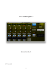
TH-S VideoEngine3D User Manual ©APB Tools 2009 1 Contents Introduction..........................................................................................................................................3 Feature Overview.............................................................................................................................3 Minimum System Requirements.....................................................................................................3 Installation Of The TH-S VideoEngine3D .....................................................................................4 Show Template Architecture...........................................................................................................4 Clip-based And Snapshot-based Automation..................................................................................5 The Operation Of TH-S VideoEngine3D.............................................................................................6 Program Start...................................................................................................................................6 Clip-Selection .................................................................................................................................7 Start-Stop Function On The Keyboard............................................................................................8 Pause Function For Layer A On The Keyboard..............................................................................8 Simultaneous Start/Stop Of Several Machines (see also <Cmd> <T>).........................................8 Loop-Function.................................................................................................................................8 Autocue-Function............................................................................................................................9 Autocue "Play through"-Mode........................................................................................................9 Stop -> Autocue In The Setup Menu ..............................................................................................9 Time Display....................................................................................................................................9 Time Bar For The Duration Of The Cue.......................................................................................10 Scrubbing.......................................................................................................................................10 Non-destructive Start/Stop/Loop Point Definition........................................................................10 Fastforward/Fastrewind.................................................................................................................11 Big Time (<Cmd> B).....................................................................................................................11 The Fader Section...............................................................................................................................12 Configuration Of The Video-Audio Ratio.....................................................................................12 Fader Automation Preview............................................................................................................12 Alternative Saving Of The Fader Position.....................................................................................13 Nominal Level Adjustment............................................................................................................13 Fader Automation On/Off Storable In Snapshot...........................................................................13 The Meta Player.................................................................................................................................14 Non-Destructive Organisation Of The Playlists............................................................................14 Operation To Copy Clips Using “P”aste In The META-Player ...................................................16 Copy A Complete Playlist Between Two Players Using <Alt> P.................................................16 The Screen Setup window..................................................................................................................17 Snapshots Of The Screen Setup Window......................................................................................18 Interpolation Between Saved Snapshots........................................................................................18 The Video Matrix...........................................................................................................................18 Display Of The Frame Rate...........................................................................................................19 Real-time Compositing / Photo-Editing Effects............................................................................19 Live Masks.....................................................................................................................................21 The Mask Editor............................................................................................................................22 Screen Setup Parameter Overview................................................................................................23 Geometrical Functions ..................................................................................................................24 Automatic Rotation........................................................................................................................24 Freeze function .............................................................................................................................24 Colour Correction..........................................................................................................................24 Geometrical Form Of The Imaging Surface (Shape).....................................................................25 Pre-Defined Geometrical Shapes...................................................................................................25 Shape Definition Window .............................................................................................................27 2 User-Definable Geometrical Shapes (Freehand)...........................................................................29 Freehand Examples........................................................................................................................29 Projection On 3D Models (3D.obj Format)...................................................................................31 Edgeblending......................................................................................................................................32 Offset.............................................................................................................................................32 Area................................................................................................................................................33 Fade ...............................................................................................................................................33 Gamma...........................................................................................................................................33 Colour correction...........................................................................................................................33 Example : Edgeblending For 4 Screens Horizontal.......................................................................33 Live Video Inputs...............................................................................................................................34 Camera Settings (<Cmd> J)...........................................................................................................35 DV Remote....................................................................................................................................35 Netplayer............................................................................................................................................37 Configuration ................................................................................................................................37 Global snapshots.................................................................................................................................38 Lock / Unlock Show (In The "Setup" Menu)................................................................................39 Timecode Trigger...............................................................................................................................39 Play All Selection..........................................................................................................................40 Autostart.........................................................................................................................................40 Easy-Batch Converter.........................................................................................................................40 Setting The MIDI-communication.....................................................................................................41 Start / Stop Remote Control...........................................................................................................42 Next/Previous Clip Layer A and Layer B......................................................................................42 MIDI NoteOn Trigger....................................................................................................................42 Snapshots.......................................................................................................................................43 Fader Start......................................................................................................................................43 Annex.................................................................................................................................................44 USB Remote Controller (USB20/JogRemote)..............................................................................44 SpeedConsolidator ........................................................................................................................46 VideoEngine3D DisplayCheck......................................................................................................46 Goodies Folder ..............................................................................................................................48 Remote Control Via Network........................................................................................................48 Remote MIDI Note Values............................................................................................................49 Multichannel Audio With The TH-S VideoEngine3D..................................................................51 Example: Large Scale HD Projection............................................................................................53 Euphonix MC Control...................................................................................................................54 Comparison Chart SOLOPlayer2 / SOLOPlaye3D / VideoEngine3D..........................................59 Editor: Florian Fischer 2009 3 Introduction With the TH-S VideoEngine3D, the growing need for quality and flexible video playback in theatre, ballet, events shows, etc. is taken into account. The TH-S VideoEngine3D uses 5 independent “video machines” which make up to 999 Video-Clips (5x127 directly addressable via MIDI) through an intuitive Playlist-Organisation (META Player) per Drag & Drop easily manageable. In each of the four “Video Machines” it is possible to independently start and stop and also crossfade two A-B players. The fifth machine is used for output in studio but can also be used as playback-machine. For each video clip the start/stop/loop times as well as different autocue-modi can be individually defined. Furthermore 4 analog Live SD-Video Signals, any pictures as well as directly created masks can be added or used as composite source. For the four full HD Outputs there are 18 filter-effects and 26 compositing-effects inclusive RGBcolouring in real-time available at the moment (expandable plugin-structure). All player and live signals can be delivered via integrated video-matrix to any output. 3D image-position, -size, warping and edge-blending as well as all effect parameters can be saved and restored as snapshots , which allows extremely fast modifications of complete playout-situations within a show. Feature Overview • 5 OpenGL render engines on GPUs • 9(!) Player with 5 discrete DVI outputs • 26 RT compositing effects (Full HD) • 18 RT filter effects (Full HD) • Real-time RGB picture colouring • Video matrix / Quadscreen projection • 2x stereoscopic projection • 3D Picture-in-Picture function • MIDI/USB/GPI/Ethernet – remote • Support of all Quicktime codecs • Support of up to 8 integrated audio channels • Integrated batch converter Minimal System Requirements MACPRO 8-CORE, MIN. 4 GBYTE RAM, VIDEO-DISK OR RAID, MIN. 2X ATI 5770 (PCIe) 4 Installation of the TH-S VideoEngine3D TH-S VideoEngine3D is copy protected. Start the TH-S installer included on the CD-ROM and follow the instructions. After the first run, the TH-S VideoEngine3D determines a so called „Challenge-Code“ (a long string of chars in upper case) from different machine parameters. This code has to be transferred via phone, fax or email ( [email protected]) to APB Tools. Usually a “Response Code” is transmitted back within 1 work-day. After entering the Response Code by the user, this version is authorized on this CPU. Note: The installer offers a 30 day trial-mode, so your work can immediately begin. Exception: The SoloPlayer3D is using a portable USB-Dongle as copy-protection. In case of a hard-disk failure and the need to use a new hard-disk, the trial-mode is also working, so that a interrupt-free workflow is provided all the time (sufficient backup of the video files implied). On your hard drive a „Show Template“ folder is created. It is important for you to create a complete copy of the original folder for each project you work on. This can be done manually (E.g. <Cmd>D duplicate) or by the installer. It makes sense to rename the copied folder referring to your own desires or project-name. For starting the show, just open the appropriate folder in the program. Hint: Create an alias of that program according to your own desires and place it on your Desktop. Important: Deactivate your system-wide autoplay function of CDs and DVDs. Otherwise an inserted disk will start immediately and TH-S VideoEngine3D won't be able to access it. The “Show Template” and other utilities will be placed in the Application's folder on your system's hard-drive. From there it can be easily copied to any volume. Show Template Architecture TH-S VideoEngine3D works with a folder structure that stores all information of a show including the program itself within a “Show Template” folder. This means new shows are created by copying and renaming of a Show Template. This can be used to create a copy of a certain production state and work on with that one. For this working method it is recommended to consolidate the video files relatively late in the production process (see “Speed Consolidator”). Please take care that the program itself inside the “Show Template” folder must not be renamed. 5 Clip-based and Snaphot-based Automation A clip includes the actual video file, the start/stop-time parameters, loop-/autocue-settings etc. (see below). In practice, this means the user can individually set loop-points, levels etc. for every clip(video file). All settings are saved AUTOMATICALLY. Once a user has configured a correct clip the settings are always available without the need for worrying about saving of single parameters. This “auto-save-to-disk”-function doesn't apply for snapshots, which have to be explicitly saved (“Save” button in the “Screen Setup” window or <Shift><Enter> on the numeric pad. Listed below are all saved settings within one clip(video file): LIVE CAMERA SWITCH LOOP SWITCH AUTOCUE SWITCH START/STOP and LOOP POINTS (non-destructive) FADER POSITION FADETIME All playlists are saved as textfiles in the folder MEDIACONTAINER/DV_SUPPORT and can be edited with every text editor offline. Listed below are all settings saved in a “Snapshot” of the “Screen Setup” window(“Save”button). These parameters are saved in a file called “presets”. • all geometric XYZ-settings, such as position, rotation, scaling, 4:3 / 16:9, shape, and their parameters within the "Shape Definition" window. • Setting the video matrix and their mask assignment • Compositing and PiP routing settings • RGB-A Colouring •All edge blending parameters such as area, fade, gamma curve, offset and RGB colouring of the transition areas. All of the selected effects with their respective parameters. Listed below are all settings saved in the global snapshot <Shift><Enter> in the “Showfile” • current video file pair (A / B layer) of the machine • Snapshot name • Program Change number (MIDI PGM CHG) • Midi In/Out port • Midi program change port • And all parameters of the Screen Setup Snapshots above 6 The Operation of TH-S VideoEngine3D Program Start TH-S VideoEngine3D is started by double-clicking on the program symbol (while initialising no operation of the program is possible for a few seconds). The program can be controlled as follows: Using the remote control Euphonix MC Control Via MIDI Note-On-commands (see Appendix) With USB-input devices With the keyboard The controls of the graphical user interface are pretty self-explanatory. Each of the four machines has two playback-layers which can be crossfaded, layer A above (yellow) and Layer B (blue) below. Both Layers have a common logic: a start/stop/pause-button, a playing time display and the notification of the currently selected clip. The assignment of the video clips to the respective playback machines can be done by: moving a video file/folder/volume onto the surface of a machine (top half) moving onto the surface of the appropriate machine in the META-player All clips of a machine then can be found in the pop-up lists of both layers. 7 Clip-Selection To select a clip, simply click on the clip name of a layer and hold the mouse button pressed, this opens the selection list (pulldown menu) of the layer. Move the mouse pointer to another file and let go off the button, so this file is selected from now on. For every A-Layer clip, an individual corresponding clip can be selected in the B-layer, which then automatically is called with the A-layer clip. The A-layer parameters set for each clip loop/start-endtime apply also on the B-layer for the same clip. When starting the clip, the program fades automatically to the respective layer. Fading times can be set for every A-B clip pair in the fader section. Clip pairs can be incremented/decremented with the following key combination: Machine M1 M2 M3 M4 Netplayer Decrement <Ctrl> q <Ctrl> w <Ctrl> e <Ctrl> r <Ctrl> t Increment <Ctrl> a <Ctrl> s <Ctrl> d <Ctrl> f <Ctrl> g Hint: the increment/decrement keys are below the number key, which identifies the video machine (M1⇔1, M4⇔4 etc.). 8 Start-Stop Function On The Keyboard The machines also can be started and stopped by using the following key combinations for start/stop(toggle): key F1 <Alt> 1 F2 <Alt> 2 F3 <Alt> 3 F4 <Alt> 4 F5 F6 player M1 Layer A M1 Layer B M2 Layer A M2 Layer B M3 Layer A M3 Layer B M4 Layer A M4 Layer B Netplayer DV Remote Pause Function For Layer “A” On The Keyboard The key combination for switching On/Off is <Shift> 1-6 according to the player numbers. Simultaneous start/stop of several machines (See also <Cmd> <T>) F unction All STOP: All PLAY: All Pause: All Isolate: Key Combination <Cmd> 0 <Cmd> 1 <Cmd> 4 <Cmd> 7 Loop-Function All machines have a Loop button which switches loop function on and off. Loop function can be set for all machines together using the entry “Loop All” (<Cmd> L) in the Function Menu. With Loop function turned on, the current clip is repeated endlessly between the selected start/stop times. 9 Autocue-Function All machines have a Autocue button which switches Autocue function on and off. Autocue function can be set for all machines together using the entry “Autocue All” (<Cmd> A) in the Function Menu. With the Autocue function turned on, the player automatically jumps to the start point of the next clip, after the current clip is stopped or has finished. Autocue "Playthrough"-Mode The Playthrough mode allows continuous playback of entire groups of clips. For every clip the Playthrough mode can individually be set by holding <Shift> while clicking on the button “Autocue”. This mode automatically starts the following clip when the current clip is finished or stopped. (Depends on the mode “Stop to Autocue” in the menu “Setup”) Stop -> Autocue In The Setup Menu If a currently playing file is stopped while in Autocue or Playthrough -mode, by default the machine remains in the same Cue for later restarting. By choosing “Stop” → “Autocue” this behaviour is set for all machines. Stopping now lets the machine skip directly to the next clip. (IMPORTANT: Also in Playthrough mode) This is useful when a long show scene has to be stopped manually after a not defined time period and the next cue shall be played immediately. According to this, complete playback sequences can be easily defined. Time Display By default each video file starts at playing time 00:00:00.0. If you want to change this starting point to another position in the file, choose the corresponding file in the A-layer and mouseclick into your time display. Now hold down the mouse button and move the cursor up or down to set the new time. 10 Alternatively a starting point can also be set via the time-slider, which is placed above the play/stop-keys (see below). Hint: A new starting point can also be set while the player is running (for example while you notice that a video file is too short and you want to restart it at a point inside the file). On Re-clicking the Play Button the clip is played immediately from the new start time. By clicking the small clock next to the play time counter, the counting-direction is reversed: the remaining rest-time is displayed. Time Bar For The Duration Of The Cue Each player has a red time bar over the width of the current player surface, which indicates the passage time of the currently playing cue within the start/stop boundaries. By mouseclicking on the red bar one can easily navigate through the whole video clip. Scrubbing By pressing the <Alt> key while moving the time bar, the depending video-picture can be shown ( the player has to be set to “Pause”-mode, within the MC Control it is sufficient to touch the Scrubwheel. Non Destructive Start/Stop/Loop Point Definition In the player window, under the time display is a white bar which represents the total length of the current clip (video file). After the first start of a video file it changes to solid bright green, which corresponds to the selection of the whole video file (0 seconds – end of file). By Clickdragging (moving the mouse in clicked mode) in the bright -green area now a startand end-time can be set non-destructive. 11 By Clickdragging on the left in the bright green area, the start time can be changed. By <Shift> Clickdragging in the bright green area, the stop time can be changed All time settings can be changed while playing. The new times are saved automatically and are active the next time the video file starts. If the LOOP function is turned on, start and stop points are used as loop points Example: If a temporarily well defined start point (E.g. 1min25sec after start) shall be approached, this can happen through Clickdragging in the time display: 1) By Clickdragging in the “ones” (sec) scroll up to 5 2) By Clickdragging in the “tens” (sec) scroll up to 2 3) By Clickdragging in the “ones” (min) scroll up to 1 Start point is 1min25sec. Fastforward/Fastrewind In Addition to the start buttons, there is a slider for fast forward and rewind. If LOOP is set, the clip is looped forward/backward. After releasing the mouse, the original speed is restored. Big Time (<Cmd> B) The time display of machine 1-5 is displayed in large format. By clicking in the players name(Pop-Up) in the Big Time Window you can choose different machines. This window can be moved freely through all displays. 12 The Fader Section The first four Faders are used to fade between the A and B layer of the machines. Click on the word “fade A” and “fade B” to automatically fade to the corresponding Layer. To cancel the fade you have to press “Stop”. The Fading time can be varied by every clip by Clickdragging in the number-field below. If you use the Euphonix MC Control you can suspend temporarily the Fader Automation by touching the appropriate fader. Setting The Video Ratio The green slider to the right of the faders are used to adjust the ratio of the video level to the audio level. If the soundtrack of a clip is too loud, just drag the fader to the desired level and adjust the green slider to the level of the video signal. This setting is clip-based saved. Fader Automation Preview The red sliders next to the faders allow showing up a preview as well as setting the fader position for the current cue shown in the pop-up menu. Case 1) While playing you can scroll through the playlist, the saved level values of the following cues(red) are displayed. By Clickdragging the level of the current cue can be changed (without the need to play it directly) and is immediately acquired into the automation. 13 Case 2) The sliders can also be used to set the automatic value for the next start of the current playing cue without triggering again. On the next start the setted value is instantly active. Example a) After the playback of a couple of cues you notice that every clip is tending to be ca. 10dB too loud. While one cue is playing, all following cues can be regulated premature by 10dB. Example b) The current cue shall be 6dB louder on the next play: Just raise the automation level by 6dB → on the next start it will be played with +6dB. Alternative Saving Of The Fader Position The fader position is alternatively saved to the current cue by pressing the “ → ← “ Button above the play/stop keys. The green LED shows if the displayed value is still equal with the saved value after moving the fader (tolerance +/- 0,4 dB). On new created cues (-----------------) the default fader position is 0dB. Nominal Level Setting By clicking on the player name in the fader window, the current clip is set to 0dB and this value is stored in memory as new level. Fader Automation On/Off Storable In Snapshot On enabled (default) the affiliated fader position for every cue is automatically retrieved. By clicking the -Button, the fader automation for the respective machine is turned off. This setting can be saved in a snapshot. Regarding the fact that the first snapshot is automatically loaded, you can create a first snapshot without fader automation, which is then used as default setting. IMPORTANT: The automation values can be configured despite the fader automation turned off by using the level slider or the -button. This allows a simple approach to the right level without automation. If the right level is found, the automation can be turned on. 14 The Meta Player The META Player is used to start clips and elementary organization of playlists in the Designand Beta-Phase, while the Main-window is especially suitable for the presentation. Basically the META-Player opens by pressing the -Button in the player, the “M”-key on the keyboard or by selecting the affiliated entry in the menu. Non-Destructive Organizing of Playlists Single Video Clips, Folder, CD's or whole Hard-Disks with video clips can be directly linked to the respective META-Player by pulling them to the affiliated player columns • The pulling of a video file to a player replaces the current video file. Empty clips are “filled”, existing video files replaced. • If an existing video file is replaced, all settings like loop points, autocue etc. still remain. If these parameters shouldn't be retained youu have to use “I”nsert and “P”aste (see below). • If you want to add several files at once to a player you have to use a folder. • Dragging a folder, a CD or a hard-disk-volume to a machine replaces the current playlist from clip 1 up to the count of video files the folder contains. By moving certain clips in a playlist you can create a combination from different video archives very fast. You can also playback various titles of a CD/DVD simultaneous on different machines and consolidate directly if you want. 15 The function buttons in the META Player "I"nsert -> adds an empty clip (--------------) on the current position "R"eplace -> opens the file selection box and replaces the current file by the selected file "D"elete -> deletes the current clip, following clips fit into the gap "C"lear -> the whole playlist is getting erased and “Default clips” created "P"aste -> copies the saved settings from one cue to another "<Shift> P"aste -> copies saved settings inclusive file name to another position „<Alt> P“aste -> copies the whole playlist PLAY/STOP Taste -> simultaneous start/stop of selected files (selecting by click on clip number) PLAY/STOP Red Column -> start/stop of a entire row in the META Player grid. Operation to copy clips using “P”aste in the META Player 1. 2. 3. The settings of the last played clips are held in memory. Clicking on the desired clip(STOP) defines the target. Pressing “P”aste copies all settings onto the target-clip <Shift> „P“ additional copies the file name IMPORTANT: Start/Stop-times are also copied 16 Copy A Complete Playlist Between Players Using <Alt> P Pressing <Alt> P opens the following dialog Now you can select the target machine on which the playlist shall be copied. After the selection press “Copy Playlist” and the whole playlist will be copied. Examples: Example 1: If you want to copy a clip which is three times used with all settings to point 23 24 25 of the playlist, you first have to play it briefly. Thereafter select number 23 and click “<Shift> P”. Thereafter select number 23 and click “<Shift> P”. Thereafter select number 23 and click “<Shift> P”. Example 2: 3 Additional clips shall be added before clip 1: Click clip 10 (stop or play-column) Press “i” three times → empty clips are created before clip 10 Thereafter fill with desired files by drag&drop. Example 3: Different video file archives shall be combined. Drag&Drop the first folder onto the player, a playlist is created Click on clip 1 (Stop- or Play column) press “i” ten times → all clips move ten digits backward Add the second folder with 10 video files, the ten “empty” clips are filled and a combined playlist is created. 17 Example 4: A certain video file shall be played with MIDI Note 45, CH11, another one with MIDI Note 23, CH14, Click on Clip 45 in machine 1 (Stop- oder Play column) Assign File via drag&drop or "R" to this clip Click on Clip 23 in machine 4 (Stop- or Play column) Assign file via drag&drop or "R" to this clip. The Screen Setup Window The Setup window contains all image, effect and routing-settings of the TH-S VideoEngine3D as well as the preview of the monitoring machines. Open the window with the key combination <CMD> E or by clicking on the Screen Setup Button in the main window. 18 Snapshots Of The Screen Setup Window The setup section has its own snapshot function where all image, effect and routing-settings can be saved. To save a snapshot just select the desired entry in the field “Store”(red) and press the “Save” Button. To recall the snapshot select the fitting snapshot number in the field “Recall”(green). Alternatively snapshots can be activated by selecting them via pressing the keys <+> and <> on the keyboard and pressing <Enter>. (MC-Control see below) Setup-Snapshots are saved as part of the global snapshots and activated within these. This means if you create a snapshot in the main window, the current setup-snapshot is connected and activated when selecting the global snapshot. Interpolation Between Saved Snapshots The field “Recall” can be scrolled in the area behind the comma after the activation of the button “i”.(The next update will allow a interpolation over a defined time-domain) This leads to an interpolation in the saved setup settings and can be used as live optical effect. The Video Matrix The Video Matrix routes the outputs of the machines to the physical outputs of the graphics card. Every screen can be played by one machine but a machine can play several screens. The configuration is saved into the setup-snapshot. 19 Display Of The Frame Rate On the upper right of the Setup window, the current achievable frame rate is displayed(max 50 fps). The preview button is used to stop the monitoring and save system resources at a high system activity to gain additional fps. Real-Time Compositing / Image Editing Effects By clicking the pulldown-menu under monitor fields, you get the options for routing the Composite Sources. The output of a machine here can be directed to the effect input of one or multiple screens. For example if you select “Comp->1” for M2, the output signal of the second machine is routed to the effect input of the first screen. „Comp-> 1-3-4“ would route the signal to the effect input of screen 1, 3 and 4. The source signal is splitted, this means the output signal of the respective machine is not changed. 20 Compositing Effects You can selected the desired Compositing Effect in the effect menu. In the Number Field beneath the Selection Field you can vary the intensity of the effect by clickdragging. For fine adjustment the number after the comma can be scrolled. By clicking into the yellow field, the pulldown-menu opens. (MC-Control see below) Image Editing Effects In addition to the 26 available realtime compositing effects, there are 25 image editing effects per screen available which can also be selected in the effect menu. You can select one effect per screen. The assignment as well as the respective parameters can be saved in a snapshot. The effects are integrated in a plugin-structure so you can expand your library day by day. A list of the certain functions can be found in the appendix 21 Picture-in-Picture By selecting the option “PiP->2” in the pulldown menu under a monitor window you can insert the complete 3D picture of one screen into the picture of a second screen. With this you can fade in a live camera in front of a running clip for example or merge 3D scenarios from 2 independent videos. If the picture doesn't show up instantly after selection of the PiP function, mostly it is setted “behind” the other picture so that you have to correct the Z parameter. According to this, corporation logos, live pictures or 3D objects can easily be inserted. IMPORTANT: For performance reasons you have to ensure that both pictures are calculated on the same graphics card. (see also Annex “Large Scale Projection HD”). Live Masks Beneath the video matrix in the setup window there is the menu for the mask functions. For each of the four screens a mask can be set or created and finally routed over a compositing effect into the video image. According to this you can partly cover the video output, for example in places where you don't want to have a projection like door blends from spotlights. A counterpart would be a mask which covers a complete image and is only transparent at certain spots, which means you only project on little areas. But also as image effect or to blend in own logos, masks are useful. For a standard application select the effect “Composite/multiply” in the “Effect” pulldown menu of the corresponding screen and set the intensity value to 1. The menu point “Picture” opens a file dialog to select a picture file as mask template. The menu point “Livemask” opens the mask editor and you can create own masks and save as picture. 22 The Mask Editor The User Interface of the Mask Editor can be compared with a drawing program. To draw just click in the editor window and drag the mouse. If you hit the <Shift>-key while drawing the colour changes from black to white. A click on the “A” upper left in the window inverts the background colour of the mask. A click on the circle symbol upper right in the window switches between the rectangle and circle drawing tool. The size of the drawing tool can be configured by clickdragging on the digit area in the upper middle of the window. To save your mask click on the “Save” button and select name and destiny in the file dialog. The mask is saved in a picture file and can be edited by an external program. This picture again can be loaded and saved to a snapshot. The colour palette is used for colouring the mask background. By switching from “Draw” to “Move” and simultaneous pressing <Shift> the effect of a chasing spot can be imitated on the current played clip. The diameter of the spot matches to the diameter of the drawing tool configured above. You can see which mask in which screen is active in the preview window next to the masselection. The preview can be switched between the screens by the pulldown menu. 23 Overview of the Setup Parameters The big difference to conventional video projection processes is that VideoEngine3D projects all video images in principle on any 3D Objects. This means a common format-filling video image means in TH-S VideoEngine3D a projection of a 2D area in a 3D room. In the setup window you can set position, form and direction of this area. This happens by clickdragging in the corresponding number fields or by direct touch&move of the 3D model in the setup window with the mouse. Here also a fine adjustment of the parameters happens by clickdragging on the number after the comma. Screen ratio (4:3 / 16:9) Image position in 3Droom Rotation in 3D room Image scaling Gild Transparence Colour correction Effect selection Effect intensity Selection of 3D object(cube, sphere..) Detail settings 24 Geometrical Functions Position [X,Y, Z] Moves the image in X(right and left), Y(up and down) or Z(close and away to spectator) -axis. Rotation [X,Y,Z,W] Rotates the image on the X, Y, Z axis and tilt it over a virtual sphere with the angle “W”.This way of rotation allows a simple usability with the mouse in 3D room by clicking the model moving around. Click on the 3D model while holding the <Alt> key: you can now move the image in the Z-axis, which means into the image plane or out of it. While holding <Cmd> <Left Mouse click> you can move the image in X and Y -axis. When pressing <Shift> <Left Mouse click> the movement on the X respectively Y-axis is limited, depending on which movement was made first. Scale [X,Y,Z] Tugs/compresses the image in X/Y-axis. Two-dimension objects are not scaleable in Z-direction. Automatic Rotation With selected button ”A” (Animation) and releasing the mouse, the model(projected image) will continue moving into the direction of the last mouse movement. With the speed of your mouse movement you control the speed of the rotation. A click on “A” or into the model stops the movement. Reset Function A click on “R” sets all geometrical parameters to “Default”. Freeze Function By clicking the button “F” right to the model window, the current played image freezes. With the key combination <Cmd> <F> all played imaged of all screens freeze simultaneously. Colour Correction In the fields R G B you can colourize or correct the image. The field “Alpha” is used to configure the transparency / brightness of the image (see Picture-in-Picture function) When working with multiple beamers you can easily correct differences in colour between the individual machines with this. 25 Geometrical Form of the Surface (Shape) By clicking in the field “Shape”, a pull-down menu opens where you can choose the geometrical shape on which the image is projected. Pre-Defined Geometrical Shapes You can select Plane, Sphere, Cube and Cylinder. Projection on plane: This corresponds the standard-case of a two-dimension projection. Here the shape can be configured by the Scale-Function and the “Shape-Function described below. Projection on sphere: The video material is projected onto the surface of a sphere. Again you can manipulate the output with the “Scale-Function” and “Shape-Function” described below. Projection on cube: The used video material is projected on the surface of a cube. Manipulation is done through “Scale Function” and “Shape Function” described below. 26 Projection on cylinder: The video material is projected onto the surface of a cylinder. Again you can manipulate the output with the “Scale-Function” and “Shape-Function” described below. A reflection onto a cylindrical surface is for example suitable for a projection on a cyclorama or similar shapes in theatre. If your projection-shape has the form of a sphere, by choosing “sphere” as shape the image can be projected distortion-free(e.g. A world map on a ball) 27 Shape Definition Window By clicking on the magnifying-glass in the setup window, you can get more detailed configuration options concerning the geometrical form of the shapes: Plane: In the plane control field you can set width and height of the projection shape in X/Yaxis TopX defines the width of the top edge of the image (default 1.11). BottomX defines width of the the bottom edge of the image (default 1.11). LeftY defines the height of the left edge of the image (default 0.84). RightY defines the height of the right edge of the image (default 0.84). Sphere: In the sphere control field you can select the diameter as well as the part of the shape of the sphere used for projection. Diameter defines the diameter of the sphere (default 0.7). ɸ X1 defines the start point (degree) of the horizontal projection angle onto the sphere (default 0 degree). ɸ X2 defines the end point (degree) of the horizontal projection shape onto the sphere (default -360 degree). ɸ Y1 defines the start point (degree) of the vertical projection shape onto the sphere (default 0 degree). ɸ Y2 defines the end point (degree) of the vertical projection shape onto the sphere (default 180 degree). 28 Cube: In the cube control field you can select the size of the cube-shapes in X,Y,Z-direction. Cylinder: In the cylinder control field you can select height/width of the part of the cylinder as well as the shape used for projection. TopX defines the width of the top edge of the cylindrical sector (default 1.11) . BottomX defines the width of the bottom edge of the cylinder sector (default 1.11). Y defines the height of the cylinder sector (default 0.84). ɸ X1 defines the start point in degree of the horizontal projection angle onto the cylinder sector (default 0 degree). ɸ X2 defines the start point in degree of the horizontal projection angle onto the cylinder sector (default 180 degree). In the pulldown-menu “Surface” you can choose wether the image shall be projected on inand outside or just in- OR outside of the 3D model. With the menu “View” you can switch the art of presentation from normal- to point- or gridmode. The number fields “Grid” and “Points” beneath the menu are used to define the line width respectively point size of the figure. The key combination <Cmd> <g> sets the presentation of all 4 screens on grid-mode. Camera: The camera position specifies the point of view of the spectator in the 3D universe. All values for the objects as well as the camera position are optimized to the standard projection. If the camera is moved in the Z-axis, all projected objects show up bigger or smaller. If the camera is moved in X/Y-axis all objects seem to be moved to the right or left, respective up or down. Look at: With the “Look at”-parameters you can define the looking direction from the position of the spectator. “Camera” and “Look at” should NOT be changed in general. Anti Tearing: This function implements the forced synchronisation of physical and calculated refresh rate. Hereby eventually appearing synchronisation-artefacts can be minimized Free Definable Geometrical Forms (Freehand) The freehand function is especially suitable for all situations where projections on various shapes have to be corrected from one or multiple beamers in different positions. 29 After selection of “freehand” the scene can be manipulated directly via mouse! This means the mouse has to be moved in the projected image. The count of control points selected in the control field corresponds to the anchor points for the image manipulation. The image which is manipulated by “freehand” can be normally positioned and rotated vie the geometrical possibilities in the model window. Freehand Examples If you only use 2 control points, you can touch the edge-points of the image and move them to any position you want. If you use more than one control point, the anchor points of the image can be touched and moved. In the standard case n-1 anchor-points are interpolated to calculate the distorted image. 30 For extreme distortions the number of interpolation points can be set independent from the control-point-count. If you have setted a distortion, your configuration can be saved into the current snapshot with the “Save”-Button. Projection Of 3D Models (3D.obj Format) 31 When selecting “3D.obj” in the pulldown-menu, 3D Models in the *.obj “Alias Wavefont”format can be loaded as projection surface. This allows for example to project CADgenerated models or construction drawings onto three dimensional bodies. After loading a 3D object with the “Read” button (item must be in the MEDIA CONTAINER/3D OBJECTS folder), the loaded Image appears as projection on the surface. The loaded 3D object can be variously positioned and rotated in the model window. Because of the vector based representation of the 3D-objects, they can be scaled up & down without loss of resolution. The picture on the 3D surface can be manipulated by the following parameters. Mapping: Simple projects the rendered image as a simple texture on the surface of the loaded object (default). Obj.Space projects the rendered image relative to the object coordinates as texture on the surface of the object. Reflection projects the rendered image mirrored to the surface of the loaded object. Eye Space projects the rendered image relative to the viewer coordinates. Material: Colour uses exclusively the colours of the image Diffuse uses additionally the diffuse components of the 3D object All uses additionally all material components of the 3D object Draw: determines in the case of a composited model which part of the object is used for projection. 0 uses all included sub-objects. In the Pulldown-menu “Surface” you can choose if the image should be projected both on the inside and outside or only on in- or outside of the 3D model. With the menu “View” you can set the kind of representation to “normal-”, “point-” or “gridmodel”. The number fields “Grid” and “Points” beneath the menu are used to set up the line width/point size. The button „Lighting“ allows to enlighten the 3D object, so a more realistic presentation of the object in the 3D-space is possible.. 32 Edgeblending By clicking on the magnifying-glass icon next to the bottom of the Setup-window, the device area for the edge-blending is opened. Enable the edge blending function by clicking in the edge-blending labeled field(blue). Choose in the pull-down menu a setup which fits the arrangement of your screens(Eg “Hor. 1-2-3-4” means 4 screens in horizontal arrangement). Beneath there is the option “resolution” in which the native resolution of the projectors should be set(when using lower resolutions than 1024x768 px you should always work with 1024x768px setting). This sets all edge-blending parameters to the resolution-specific standard-cases. The parameters can be configured by click-dragging in the number fields. Fine-tuning can ever be made by scrolling in the number-field after the comma. Here is an explanation of each parameter: Offset Moves the sub-image in X and Y direction (default 0) Area Determines the part of the complete picture which is presented on the Screen( default 0 0 1 1, whole image) Fade Determines the size of the transition region of the specific Screen (in 1024x768px Example: ¼ of the screen) Gamma 33 Brightness during the transition region (default 0.5 = linear) Colour Correction Colour correction in the transition area (default 1) Example : Edgeblending for 4 Screens horizontal 0) Choose the desired shape of your projection surface (Plane, Sphere, Cube, Cylinder, Freehand, 3D.obj). 1) Set the resolution in the “Resolution”-pulldown menu to the native resolution of your projectors 2) Load the test-film according to your resolution in the “Resolution”-Pulldown Menu (Eg Testfilm1024x768). 2a) Align all 4 projectors so that the vertical blue lines lie one on another 2b) Correct the geometric distortions/shifts as far as possible with the geometric model of the setting window so that the blue lines as well overlap. 2c) When using the “free hand” feature, you take the corner and control points directly in the projected picture and drag the image with the mouse to the desired shape. 3) In the “Edgeblending” Pulldown-menu choose “Hor 1-2-3-4”. The overall picture should now resemble the final result. 3a) In the number-fields the standard-edgeblending values should appear. 4) Now the overlap of the individual images should be optimized.. Therefor the corresponding “Fade”-Values are varied to get an optimal adjustment of the Extension of the brightness between the images. Hereby ideally, the corresponding values should be equal. (Eg left and right edge). If there is still a visible transition between the images, you can vary the “Gamma” values for a better optimization in the brightness gradient. The “Gamma” value determines how 34 linear the brightness course on the edge of the image should be made from light to dark. With this you can relatively easy compensate reflection properties of the projection surface. If you use extremely wide angle lenses you can correct colour distortions in the transition areas by configuring the RGB values on the corresponding edge. Live Video Inputs TH-S Videoengine3D supports up to 4 Live Video Inputs. With this you can include live video images from camera or other external video sources into the show. All live video inputs are routed static on Layer A of each machine. Input 1 is direct to machine 1, Input 2 on machine 2 etc.. To activate a camera input in the video-processing-chain, set a tick in the corresponding field under “Enable Live Cams”. This function can be saved in a snapshot. Click on the “Live Cam” button in the appropriate machine to show up the live display When playing a clip simultaneously on the same layer, only the sound of the clip is send to output. By Re-clicking you can switch between clip and live image. Of course you can fade to the clip in the B-layer at any time. All geometrical and effect-based settings can be used on the live-signal as well. By selecting the Button you can assign a live image to an empty clip (-----------) which is integrated to the playlist as a normal video clip. Camera Settings (<Cmd> J) 35 Via the menu „Setup -> Camera-Settings...“, by pressing the combination <Cmd> <J> or by clicking on “Enable Live Cams”, the “Camera Settings” window opens. By click-dragging of the corresponding number fields you can adjust brightness, contrast and saturation of the live images. When clicking on the field “Format”, a pulldown menu opens. You can choose between the formats PAL, NTSC and SECAM. A click on resets the configuration of the input to default values. DV Remote The Player 6 is used to control a DV deck / camera as well as the output of MIDI-ProgamChange commands By selecting “DV Remote” Player 6 can be used to remote control plugged DVCameras/decks. By moving the time bar or changing the time window via mouse, a connected DV-Device rewinds/forwards to this time and goes into pause. By pressing the Start-Button the tape is played at that certain position. Pressing the Stop button will stop the tape. With the <Shift> <arrow keys> the tape can be stepped for and backward by frame. MMC-PLAY-/STOP/LOCATE-commands are also issued simultaneously. The MIDI-commands are outputted to the MIDI-Port which is set with “PGM CHG OUT” in the bottom window. Pressing the START-key of Player 6 sends additionally the program-change-command shown in the selection window. Hereby means: 36 „Program 1“ ... „Program 127“ MIDI Prg. Chg. 0 MIDI Prg. Chg. 126 At the same time (more precisely after the PRG CHG command) a MIDI Machine Control (MMC) PLAY-command is issued to a MMC-compatible device running on the ID # 127. ID# 127 is the Default-Setting (broadcast). A different ID number can be adjusted by clicking in the player window on ID#127, selecting a different ID and releasing the mouse.. Pressing the STOP button generates a MMC-STOP command. The MMC play command is a “Deferred Play”, which is an automatic playback of tape-based machines, for example after reaching of a locate point. This is useful because of the fact that time display and time slider produce MMC locate commands as well. Click-dragging of the time bar or the time slider allows a rough adjustment of the locator starting time. The fine tuning takes place by click-dragging in the time display ( Shift x10 / Cmd x0.1 ) The locator time is rounded up to the shown 100ms in the time display, issued in a 25fs time code format. This locator time is expressed as “Full Frame MMC Locate”. The maximum locator start time is 60 minutes (DV-tape-length). The usage of a different timecode format inside the extern controlled device acceptable, since the positioning error is greater than the difference between the Time Code formats(the maximum possible positioning difference in a second when using 25fps for a 30fps extern device is 5 x 40ms = 200ms). Netplayer With the Netplayer (Machine 5) you can remote control up to 16 remote-computers with installed SOLOPlayer. The only requirement is that the computers are used on the same Network(Ethernet or WiFi). 37 Remote controllable are Start/Stop/Pause/Clipnumber/Start-Stoptimes. This means for example, that when choosing Clip 14 in machine 5 all in the network selected SOLOPlayer also switch to clip 14 and start playing after pressing the “Play” button in machine 5. Configuration The Menu Point Setup -> Remote-Player Settings... or by clicking on “Netplayer”, you get to the configuration window of the Netplayer. To set the IP-address of a SOLOPlayer instance, click in the IP-address column into the corresponding row you want to change. Now set the new IP by clickdragging on the specific fields in the number-area on bottom of the window. The labelling is also specified through clicking in the name-field of a line. By selecting the “Time”-function the player broadcasts, additional to the control commands, image numbers. This allows an optimal image-correct synchronisation of the SOLOPlayer with the TH-S VideoEngine3D. In this process, however, there is no sound output from the SOLOPlayer possible anymore. In addition you can equip the Netplayer with video files and as a local player device (Machine 5). The Usage is equal to the machines 1-4. However, there is no B-Layer to fade. Activate the local Playback via selecting the button “STUDIO OUT”. Global Snapshots On the right side of the main window there is the snapshot display. Selecting of snapshots works (as in the file selection) via clicking in the list, selecting with the mouse and releasing of the mouse-button. But you cans also get forwards/backwards with the +/- keys of the number block. On activated snapshot the green indicator glows under the snapshot-list. The snapshots are activated after their selection by pressing the (<Enter>) key of the number block or by pressing the key combination <fn> <Return> if you don't have a number block. 38 Saving the snapshots in the snapshot list is performed by <Shift> and <Enter> of the number block. Choose the snapshot where to save the new configuration without activating. After setting all the parameters, press the <Enter> key while holding the <Shift> key (or <fn> <Shift> <Return>) You can rename the snapshots by clicking on the rename button above the snapshot list. In the opening window just overwrite the old name and click OK. Delete: With DELETE the content of a selected snapshot is deleted (but not the settings in the Screen Setup window!) TH-S VideoEngine3D provides 99 snapshot storage spaces which can be accessed via keyboard, remote control or MIDI program-change-command(see Appendix). The „Showfile“ is located as a Text-file and can be edited with every text-editor. Lock / Unlock Show (in "Setup" Menu Point) In the “Show is loaded and LOCKED” mode, all changes of a show can be done, but these changes won't be written onto hard-disk. After a Reload( in the menu point “File”) or a reboot the last saved configuration is loaded. The “Lock” mode is recommended for finished shows or rehearsal-situations which are not intended to be changed. Timecode Trigger In the player window you can trigger every player individual on a previously defined timecode 39 start-time via selection of the “Sync” button. The start-time is configured by clickdragging in the “TCSet” window shown below. Open the menu „Tools-> TimeCode Trigger“ or press „<Cmd> T“. The frame rate of the MIDI-Timecode, incoming at “PGM CHG In” is detected automatically and the Start-Frames are adjusted to it. All other startup options (Mouse,MIDI,USB etc.) can be used parallel to the Sync-Mode so that the show can be run in a mixed “manual / timecode triggered” mode. Play All Selection In the TCSet you can choose which machines should be started, stopped and paused simultaneously if you use the corresponding “Play All” Commands (Cmd>0, Cmd>1, Cmd>4) or equal MIDI/USB-Remote Commands). This setting is saved in the particular snapshot. It is therefore recommended to save the required setting in snapshot 1 because of this one is automatically loaded on start-up. Autostart The Autostart function in the TCSet window starts all machines which were selected in the 40 “Play All” dialog after a delay of one minute of start-up of the program. This helps on situations when TH-S VideoEngine3D is used in a permanent installation. This setting is saved in the particular snapshot. It is therefore recommended to save the required setting in snapshot 1 because of this one is automatically loaded on start-up. Easy-Batch Converter Using the Easy-Batch-Converter you can convert audio and video files to all popular formats. Simply drag a source file or a folder with multiple source files into the Easy-Batch-ConverterField in the main window. The converter window will show up. Now select the codec and press the PLAY-button. The converted files will be situated in the MEDIA CONTAINER – folder in the sub-folder “Batch Conversion”. By clicking the magnifying glass any other destination on this machine can be selected. It is possible to drag & drop single files or whole folders directly into the Converter Window.. Files you don't want to convert can be selected in the “File” pulldown menu, a click on the “D” Button will remove them from processing. It is also possible to automatically save image files (E.g. Photos) as video file by dragging them into the window. The display length of each image can be edited in the “Default Photo length” field. The Easy-Batch-Converter allows the full range of Quicktime-supported Codecs (best results for HD-material are achieved with Apple prores 422, photo-jpeg and dvi. Setting the MIDI-Communication 41 The “Audio Hardware Is Online” window is automatically opened when the program starts up. Click on the box above the sign “MIDI IN” and hold the mouse button. Now all MIDI-ports and devices are shown. Now choose the corresponding port and release the mouse button. Repeat this procedure in the box above the sign “MIDI OUT”. The connection with your controller (MC Control etc.) is now established. In the same way you choose the devices or MIDI ports and their channels at “PGM CHG IN” and “PGM CHG OUT” All MIDI ports can be saved and retrieved in snapshots. Since the first snapshot is automatically loaded on startup you can create a first snapshot with correct chosen MIDI-port as a default value. Start / Stop Remote Control Layer A (Midichannel 1, Velocity 127): Player M1 M2 M3 M4 Netplayer DV Remote Stop C0 = 24 C#0 = 25 D0 = 26 D#0 = 27 E0 = 28 F0 = 29 Play E-1 = 16 F-1 = 17 F#-1 = 18 G-1 = 19 G#-1 = 20 A-1 = 21 Layer B (Midichannel 2,Velocity 127) 42 Pause G#-2 = 8 A-2 = 9 A#-2 = 10 H-2 = 11 C-1 = 12 C#-1 = 13 Player M1 M2 M3 M4 Stop C0 = 24 C#0 = 25 D0 = 26 D#0 = 27 Play E-1 = 16 F-1 = 17 F#-1 = 18 G-1 = 19 Pause G#-2 = 8 A-2 = 9 A#-2 = 10 H-2 = 11 Next/Previous Clip Layer A and Layer B (always switched as pair) M1 Controller 16 Value < 64 -> NEXT CUE M1 Controller 16 Value > 64 -> PREVIOUS CUE M2 Controller 17 Value < 64 -> NEXT CUE M2 Controller 17 Value > 64 -> PREVIOUS CUE M3 Controller 18 Value < 64 -> NEXT CUE M3 Controller 18 Value > 64 -> PREVIOUS CUE M4 Controller 18 Value < 64 -> NEXT CUE M4 Controller 18 Value > 64 -> PREVIOUS CUE Netplayer Controller 19 Value < 64 -> NEXT CUE Netplayer Controller 19 Value > 64 -> PREVIOUS CUE MIDI NoteOn Trigger For the triggering of clips via MIDI Note On, you have to switch the Note-On Button to “On”. This allows a triggering of the first 127 clips of every machine via the MIDI Note On 0127(Sample Mode). The Volumes are saved in the corresponding Cue. Layer A: M1: MIDI CH 11 NoteON 0-127 Cue 1 - 128 arbitrary Velocity 0-127 M2: MIDI CH 12 NoteON 0-127 Cue 1 - 128 arbitrary Velocity 0-127 M3: MIDI CH 13 NoteON 0-127 Cue 1 - 128 arbitrary Velocity 0-127 M4: MIDI CH 14 NoteON 0-127 Cue 1 - 128 arbitrary Velocity 0-127 Netplayer: MIDI CH 15 NoteON 0-127 Cue 1 - 128 arbitrary Velocity 0-127 Hint: Appropriate positioning of a „MUTE“-File (----------) can be used as “STOP” button. Snapshots Snapshots are called via PGM Change 1-99 directly (equivalent to number + Enter !) Faderstart The fader start feature is called via the MIDI program change input. To activate the fader start, you have to set source and channel of the broadcasting device in the window “Audio 43 Hardware is online” and switch the “F-START”-Button to ON. Using the NOTE ON command with velocity of 127 on MIDI-channel 1 you can start the Alayers of the machines 1-4, NOTE ON with velocity 0 stops them. The needed MIDI-note-values can be retrieved from the table below. Layer A (MIDI Channel 1): Player M1 M2 M3 M4 Netplayer DV Remote Stop 37, Velocity 0 38, Velocity 0 39, Velocity 0 40, Velocity 0 41, Velocity 0 42, Velocity 0 Play 37, Velocity 127 38, Velocity 127 39, Velocity 127 40, Velocity 127 41, Velocity 127 42, Velocity 127 Pause 45, Velocity 0 46, Velocity 0 47, Velocity 0 48, Velocity 0 49, Velocity 0 50, Velocity 0 The MIDI values correspond to the MIDI Fader-Start function of a Yamaha 02R mixer. Anhang USB Remote Anbindung (USB20/JogRemote) 44 Nach Anwahl des USB Knopfes im unteren Fenster öffnet sich der USB Remote Auswahldialog. Dort kann ausgewählt werden welche USB20 Remote für welchen Layer zuständig ist (es kann für jeden Layer eine USB20 Remote angeschlossen werden). Durch Anwahl im PullDown Menü kann auch die umfangreichere JogRemote ausgewählt werden. 45 SpeedConsolidator Der SpeedConsolidator liegt im „Show Template“ Ordner und erlaubt die Konsolidierung einer kompletten Show per Drag&Drop zu Backup- oder Gastspielzwecken. 46 Der SpeedConsolidator ist ein kleines Applet das Systemroutinen benutzt um die teils beträchtlichen Datenmengen mit maximaler Geschwindigkeit in den MEDIA CONTAINER zu kopieren und die Playlisten entprechend anzupassen. Dies geschieht entweder durch Drag&Drop eines kompletten SHOW TEMPLATE Ordners (also NICHT des MEDIA CONTAINER Ordners) auf das SpeedConsolidator Icon oder durch Doppelklick auf das Icon worauf ein Auswahldialog geöffnet wird. Für die Playlisten werden dabei jeweils automatisch Backups erstellt. VideoEngine3D DisplayCheck Das "VideoEngine3D DisplayCheck" Applet liegt in jedem "Show Template" Ordner und dient zum einfachen erkennen und zuordnen der jeweiligen Displays/Projektoren zu den entsprechenden Ausgängen der Grafikkarten. Durch Doppelklick darauf wird ein Textfile erzeugt, welches die angeschlossenen Geräte (hier rot dargestellt) an die Grafikkarten sowie deren Einstellungen anzeigt. Beispiel: 47 48 Goodies Ordner Audio: Timecode Tracks (not in Evaluation Versions) Jeweils über 4,5 Stunden optimierte SMPTE Timecode Files mit 25 bzw. 30 Frames/s zum Ausspiel von Timecodebursts über die Audioausgänge. Die Audiofiles können mit dem Editor die auf die benötigte Timecode Zeit gekürzt werden oder es kann einfach die benötigte Startzeit nicht-destruktiv eingestellt werden. Die Files starten mit ca. 3 Sekunden "stehendem" 0:00:00.0 Timecode. Audioprogramme die keine EchtzeitSampleratenkonvertierung wie TH-S enthalten können diese Files nicht im korrekten Format ausspielen.Die Timecode Files finden sich im "Goodies" Ordner der CD. Video: 1. Testfilme 1024x768, 1280x720, 1920x1080 zum einfachen Einstellen der Edgeblending Parameter 2. Videobeispiele verschiedener Größe und Codecs 3. Schwarz/Weiß Maskenbeispiele Fernbedienung über Netzwerk Sie können TH-S VideoEngine3D auch über das Netzwerk steuern. Ein Doppelklick auf Netzwerk im Midi Geräte Fenster öffnet folgendes Fenster: Wählen Sie im Verzeichnis den Computer an und drücken Sie auf verbinden. Der Computer sollte nun auf der Teilnehmer Seite erscheinen (rechts). Läuft TH-S VideoEngine3D auf diesem Computer wählen Sie im Live-Routing „TH-S VideoEngine3D “ und „TH-S VideoEngine3D “ aus. 49 Auf der Gegenstelle öffnen Sie den gleichen Dialog, verbinden die Computer miteinander und wählen dort Ihren MIDI-Controller aus. In TH-S VideoEngine3D stellen Sie jetzt nur noch die Midi Verbindung her für „midi in/out“ und „PGM CHG in/out“ . Wählen Sie dazu in den PopUps „Network Session 1“ aus. Jetzt können Sie TH-S VideoEngine3D von einem anderen Rechner steuern. Remote MIDI Notenwerte LAYER A: MIDI Channel 1 STOP: M1 Vel 127 C0 = 24 M2 Vel 127 C#0 = 25 M3 Vel 127 D0 = 26 M4 Vel 127 D#0 = 27 M5 Vel 127 E0 = 28 MIDI/DV 127 F0 = 29 PLAY: M1 Vel 127 E-1 = 16 M2 Vel 127 F-1 = 17 M3 Vel 127 F#-1 = 18 M4 Vel 127 G-1 = 19 M5 Vel 127 G#-1 = 20 MIDI/DV Vel 127 A-1 = 21 PAUSE: M1 Vel 127 G#-2 = 8 M2 Vel 127 A-2 = 9 M3 Vel 127 A#-2 = 10 M4 Vel 127 H-2 = 11 M5 Vel 127 C-1 = 12 MIDI/DV Vel 127 C#-1 = 13 LAYER B: MIDI Channel 2 STOP: M1 Vel 127 C0 = 24 M2 Vel 127 C#0 = 25 M3 Vel 127 D0 = 26 M4 Vel 127 D#0 = 27 50 PLAY: M1 Vel 127 E-1 = 16 M2 Vel 127 F-1 = 17 M3 Vel 127 F#-1 = 18 M4 Vel 127 G-1 = 19 PAUSE: M1 Vel 127 G#-2 = 8 M2 Vel 127 A-2 = 9 M3 Vel 127 A#-2 = 10 M4 Vel 127 H-2 = 11 FADERAUTOMATION ON/OFF M1 Vel 0 C-2 = 0 M2 Vel 127 C#-2 = 1 M3 Vel 127 D-2 = 2 M4 Vel 127 D#-2 = 3 M5 Vel 127 E-2 = 4 MIDI/DV Vel 127 F-2 = 5 NEXT/PREVIOUS CUE LAYER A und Layer B (wird immer als Paar selektiert) M1 Controller 16 Value < 64 -> NEXT CUE M1 Controller 16 Value > 64 -> PREVIOUS CUE M2 Controller 17 Value < 64 -> NEXT CUE M2 Controller 17 Value > 64 -> PREVIOUS CUE M3 Controller 18 Value < 64 -> NEXT CUE M3 Controller 18 Value > 64 -> PREVIOUS CUE M4 Controller 18 Value < 64 -> NEXT CUE M4 Controller 18 Value > 64 -> PREVIOUS CUE M5 Controller 19 Value < 64 -> NEXT CUE M5 Controller 19 Value > 64 -> PREVIOUS CUE MIDI NOTE ON TRIGGER Für das Triggern von Cues mittels MIDI Note On muß der Note On-Schalter im unteren Fenster auf "On" geschaltet werden. Dies erlaubt das Triggern der jeweils ersten 127 Cues in jedem Player mittels MIDI Note On 0-127 (Sampler-Modus). Die Lautstärken sind im jeweiligen Cue gespeichert. Stop über s.o. STOP oder Leer-Cue (----------). Layer A: M1: MIDI CH 11 NoteON 0-127 Cue 1 - 128 beliebige Velocity 0-127 M2: MIDI CH 12 NoteON 0-127 Cue 1 - 128 beliebige Velocity 0-127 M3: MIDI CH 13 NoteON 0-127 Cue 1 - 128 beliebige Velocity 0-127 M4: MIDI CH 14 NoteON 0-127 Cue 1 - 128 beliebige Velocity 0-127 M5: MIDI CH 15 NoteON 0-127 Cue 1 - 128 beliebige Velocity 0-127 SNAPSHOTS Snapshots werden mit PGM Change 1-99 direkt aufgerufen (entspricht Nummer+Enter ! ). 51 Multichannel Audio mit der TH-S VideoEngine3D Mit z.B. Quicktime-Pro kann jedes beliebige Multichannel AudioFile in einen existierenden Videofile eingefügt und die Kanalzuordnung bearbeitet werden. werden (copy-paste, siehe QuickTime help). 1) CoreAudio Device (Digidesign,RME,MoTU etc.) in Audio-MIDI-Einstellungen als StandardOutput definieren. System-Output (beeps etc.) am besten auf einen anderen Ausgang legen 2) CoreAudio Device in "Eigenschaften für:" auswählen und Lautsprecher konfigurieren anklicken. 3) Im erscheinenden Dialog "Mehrere Kanäle" anklicken. 4) Im PopUp Menü die entsprechende Lautsprecheraufstellung anwählen (von Quadrophon bis oktagonal auswählbar) 5) Die logischen Ausgänge (Left,Center,Right etc.) den physikalischen Ausgängen des AudioInterfaces zuweisen und anwenden anklicken. 5a) Im Ton-Kontrollfeld (Systemeinstellungen) falls nicht bereits eingestellt das Core-Audio Device als Ausgang anwählen. Damit ist die Grundeinstellung fürs Audio-Interface abgeschlossen. Es kann unter Umständen notwendig sein den Rechner einmal mit dieser Konfiguration neu zu starten. Kanalzuordnung innerhalb des Multichannel Files (benötigt QT-Pro) Bei gebounceten Files sieht die Kanalzuordnung zunächst so aus (<Cmd> J in QT-Pro) und alle Kanäle werden über den 5. Audiokanal (Center) ausgespielt: Diese Zuordnung kann durch klicken auf die einzelnen Spuren z.B. in solch eine Konfiguration geändert werden, welche dann korrekt über mehrere Ausgänge wiedergegeben wird. 52 Jetzt muß nur noch Save gedrückt werden und der Mehrkanalaudio-Teil wird über die richtigen Ausgänge wiedergegeben. Die Kanalzuordnung kann natürlich ebenfalls in jedem anderen Audio/Video Editor welcher das „Interleaved Multichannel“ Audioformat unterstützt bearbeitet werden. 53 Example: Large Scale HD Projection 54 Euphonix MC Control 55 56 57 58 59 Comparison Chart SOLOPlayer2 / SOLOPlaye3D / VideoEngine3D 60