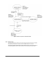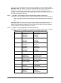
1
Security Target Version 1.21 Comex Electronics AB Page 1 (54) Document History Version Change Date Author Changes 0.1 2010-12-31 Staffan Persson Initial version 0.2 2011-01-06 Johan Anstrell Updated content and formatting 0.3 2011-03-16 Johan Anstrell Staffan Persson Updated after review from Comex and CSEC 0.4 2011-03-16 Johan Anstrell Staffan Persson Updated after review from Comex and CSEC 0.5 2011-03-24 Johan Anstrell Updated after review from Comex 0.6 2011-03-29 Johan Anstrell Updated after review from Comex 0.7 2011-05-25 Johan Anstrell Updated after review from Comex 0.8 2011-06-16 Thomas Svensson Updated 0.9 2011-06-27 Johan Anstrell Updated after review by evaluator and CSEC 1.0 2011-09-08 Johan Anstrell Staffan Persson Updated after review by evaluator and CSEC 201107-06. 1.1 2011-09-19 Staffan Persson Updated based on comments from CSEC. 1.2 2011-10-05 Johan Anstrell Updated based on comments from CSEC. 1.3 2011-10-21 Johan Anstrell Updated after comments from the evaluator. 1.4 2011-10-25 Johan Anstrell Updated after comments from MUST. 1.5 2011-10-25 Johan Anstrell Updated table 9. 1.6 2011-10-28 Johan Anstrell Updated after comments from MUST and evaluator. 1.7 2011-10-28 Johan Anstrell Updated after comments from MUST and evaluator. 1.8 2011-10-31 Johan Anstrell Updated after comments from MUST. 1.9 2012-02-03 Johan Anstrell Updated after comments from the evaluator and CSEC. 1.10 2012-03-16 Johan Anstrell Updated after comments from the evaluator and CSEC. 1.11 2012-03-28 Fredrik Larsson Johan Anstrell Updated after comments from the evaluator and CSEC. 1.12 2012-03-29 Johan Anstrell Updated after comments from evaluator. 1.13 2012-04-02 Johan Anstrell Updated after comments from evaluator. 1.14 2012-04-10 Johan Anstrell Updated after comments from CSEC. 1.15 2012-04-11 Johan Anstrell Updated after comments from evaluator. 1.16 2012-04-12 Johan Anstrell Updated after comments from evaluator. 1.17 2012-05-21 Johan Anstrell Updated after comments from CSEC. 1.18 2012-08-24 Johan Anstrell Updated after comments from evaluator. 1.19 2012-10-26 Johan Anstrell Updated after comments from evaluator. 1.20 2012-11-05 Johan Anstrell Updated after comments from CSEC. 1.21 2013-06-10 Johan Anstrell Added product article number information. Version 1.21 Comex Electronics AB Page 2 (54) Table of Contents 1. INTRODUCTION .............................................................................................................................. 6 1.1 SECURITY TARGET IDENTIFICATION ....................................................................................... 6 1.2 TOE IDENTIFICATION............................................................................................................ 6 1.3 TOE OVERVIEW ................................................................................................................... 7 1.3.1 TOE type ............................................................................................................................ 7 1.3.2 Required non-TOE hardware and software ....................................................................... 7 1.4 TOE DESCRIPTION .............................................................................................................. 7 1.4.1 Introduction ........................................................................................................................ 7 1.4.2 Product Features and Security Features ......................................................................... 13 1.4.3 Intended Method of Use .................................................................................................. 14 1.4.4 Firmware separation – Security modes ........................................................................... 15 1.4.5 States of operation ........................................................................................................... 15 1.4.6 Product Type.................................................................................................................... 18 1.4.7 Definition of the TOE ....................................................................................................... 19 1.4.8 Users and Roles .............................................................................................................. 21 2. CC CONFORMANCE CLAIM ........................................................................................................ 22 3. SECURITY PROBLEM DEFINITION............................................................................................. 23 3.1 ASSETS ............................................................................................................................. 23 3.2 THREATS ........................................................................................................................... 23 3.3 ASSUMPTIONS.................................................................................................................... 24 3.3.1 3.4 4. 5. ORGANIZATIONAL SECURITY POLICIES ................................................................................ 24 SECURITY OBJECTIVES ............................................................................................................. 26 4.1 SECURITY OBJECTIVES FOR THE TOE ................................................................................. 26 4.2 OBJECTIVES FOR THE OPERATIONAL ENVIRONMENT ............................................................ 26 4.3 SECURITY OBJECTIVE RATIONALE ....................................................................................... 27 4.3.1 Security objectives coverage ........................................................................................... 27 4.3.2 Sufficiency........................................................................................................................ 28 EXTENDED COMPONENTS DEFINITION ................................................................................... 31 5.1 6. Intended usage of the TOE.............................................................................................. 24 CLASS CCR: COMEX CARD READER .................................................................................. 31 5.1.1 Comex Card Reader Identification (CCR_IDE) ............................................................... 31 5.1.2 Comex Card Reader Status (CCR_STA) ........................................................................ 32 SECURITY REQUIREMENTS ....................................................................................................... 33 6.1 THE NFLOW SFP ............................................................................................................. 33 6.2 THE UDFLOW SFP .......................................................................................................... 33 6.3 THE CBLOCK SFP ........................................................................................................... 33 6.4 TOE SECURITY FUNCTIONAL REQUIREMENTS ..................................................................... 34 6.4.1 Version 1.21 Class FDP – User Data Protection .................................................................................. 35 Comex Electronics AB Page 3 (54) 6.4.2 Class FMT – Specification of Management Functions .................................................... 37 6.4.3 Class FPT – Protection of the TOE Security Functions .................................................. 37 6.5 7. SECURITY FUNCTIONAL REQUIREMENTS RATIONALE ............................................................ 39 6.5.1 Security Requirements Coverage .................................................................................... 39 6.5.2 Security Requirements Sufficiency and Dependency Analysis ....................................... 41 6.5.3 Unresolved Dependencies ............................................................................................... 42 6.5.4 Justification for Explicitly Stated IT Security Requirements ............................................ 42 6.6 TOE SECURITY ASSURANCE REQUIREMENTS ...................................................................... 42 6.7 SECURITY ASSURANCE REQUIREMENTS RATIONALE ............................................................ 42 TOE SUMMARY SPECIFICATION ............................................................................................... 43 7.1 TOE SECURITY FUNCTIONS................................................................................................ 43 7.1.1 User data protection ........................................................................................................ 43 7.1.2 TSF Protection ................................................................................................................. 45 7.2 THE TOE SUMMARY SPECIFICATION RATIONALE ................................................................. 46 8. REFERENCES ............................................................................................................................... 48 9. ABBREVIATIONS AND DEFINITIONS ......................................................................................... 49 APPENDIX A – PRE-DEFINED STATUS INFORMATION .................................................................. 50 Figures Figure 1: Examples of distinct areas on a finger ................................................................................... 13 Figure 2: Modes of operation for KT2USB reader ................................................................................. 17 Figure 3: Modes of operation for BioSec Reader .................................................................................. 18 Figure 4: Description of the smart card reader interfaces ..................................................................... 20 Figure 5: Class Comex Card Reader decomposition diagram .............................................................. 31 Tables Table 1: The hardware and firmware versions of the TOE ..................................................................... 6 Table 2: The ATR for the Swedish Defence smart cards ........................................................................ 9 Table 3: The ATR for the BioSec smart cards....................................................................................... 10 Table 4: Available functionality in KT2USB with different types of smart cards .................................... 11 Table 5: Available functionality in BioSec reader with different types of smart cards ........................... 11 Table 6: Functionalities of the smart card reader .................................................................................. 19 Table 7: TOE User manuals .................................................................................................................. 20 Table 8: Mapping of TOE security objectives to threats and policies ................................................... 27 Table 9: Mapping of security objectives for the environment to assumptions, threats and policies. .... 28 Table 10: Sufficiency of objectives countering threats .......................................................................... 28 Table 11: Sufficiency of objectives holding assumptions ...................................................................... 29 Table 12: Sufficiency of objectives enforcing Organizational Security Policies .................................... 30 Version 1.21 Comex Electronics AB Page 4 (54) Table 13: Command blocking ................................................................................................................ 34 Table 14: TOE Security Functional Requirements ................................................................................ 35 Table 15: Pre-defined status information to security objectives. ........................................................... 39 Table 16: Security Objectives Related to Security Requirements......................................................... 40 Table 17: Security Functional Requirements Related to Security Objectives ....................................... 41 Table 18: SFR dependency analysis..................................................................................................... 42 Table 19: PIN and fingerprint commands supported by the TOE when a corresponding smart card is used (BioSec Reader with a BioSec Card etc.) ............................................................................. 45 Table 20: Security Objectives Related to Security Requirements......................................................... 47 Table 21: Pre-defined texts within the TOE........................................................................................... 54 Version 1.21 Comex Electronics AB Page 5 (54) 1. Introduction 1.1 Security Target Identification 1.2 Title: Comex Smart Card Reader KT2USB / BioSec Reader Security Target Version: 1.21 Status: Release Date: 2013-06-10 Sponsor: Comex Electronics AB Developer: Comex Electronics AB Keywords: Security Target, Common Criteria, Smart Card Reader TOE Identification The target of evaluation (TOE) is an advanced smart card reader having electrical interfaces to a smart card and a USB interface to a host PC. The TOE exists in two product families and in three different versions within each product family: • • Comex KT2USB – The Swedish Defence series o KT2USB/U1 o KT2USB/U2 o KT2USB/STD Comex BioSec Reader – An export series o BioSec/A o BioSec/B o BioSec/C The smart card readers have the following firmware and hardware versions and product article number: Smart card Reader Hardware version Firmware version Product Article number KT2USB/U1 P20355-05 KT2USB v1.00.17 X223001-02 KT2USB/U2 P20356-04 KT2USB v1.00.17 X222001-01 KT2USB/STD P20357-03 KT2USB v1.00.17 X221001-01 BioSec/A P20355-05 BioSec v1.00.03 X423001-01 BioSec/B P20356-04 BioSec v1.00.03 X422001-01 BioSec/C P20357-03 BioSec v1.00.03 X421001-01 Table 1: The hardware and firmware versions of the TOE The main differences in hardware versions between the smart card reader versions are: • Version 1.21 There are three different layouts for the motherboard, as displayed in the table above. Comex Electronics AB Page 6 (54) • Only KT2USB/U1 and BioSec/A includes a converter functionality from galvanic USB to fibre optical USB. • KT2USB/STD and BioSec/C uses a different keypad. There are two different firmware versions, one used in the Swedish Defence series and one used in the export (BioSec) series. All six versions of the smart card reader are covered by this Security Target. 1.3 TOE Overview 1.3.1 TOE type The TOE is a smart card reader with keypad and a fingerprint reader. See section 1.4.2 for a complete list of the smart card readers product features and security features. 1.3.2 Required non-TOE hardware and software The TOE is self -contained and does not require any non-TOE hard- or software for its security. The smart card reader enables the use of compatible smart cards and its functionalities, when connected to a host PC capable of communicating with the smart card reader and the smart card. 1.4 TOE Description 1.4.1 Introduction This part of the ST describes the TOE as an aid to the understanding of its security requirements and addresses the product type, the intended usage and the general IT features of the TOE. The target of evaluation (TOE) is an advanced smart card reader having electrical interfaces to a smart card and a USB interface to a host PC. The TOE exists in two product families: • • Comex KT2USB – The Swedish Defence series o KT2USB/U1 o KT2USB/U2 o KT2USB/STD Comex BioSec Reader – An export series o BioSec/A o BioSec/B o BioSec/C The smart card reader will allow a host PC to use the functionality of the smart card while protecting the smart card and the PIN. By using the smart card reader, the host PC will be able to use the security functionality of the smart card without having to divulge or handle the PIN or any other personal information in the host PC environment. No personal information shall be stored about the persons using the smart card reader. For this reason there are no users or even administrators known to the smart card reader. However, the smart cards are personal and therefore suitable for user authentication and digital signatures. A smart card reader enables the usage of personal smart cards from the host PC. This is done using functionality of the smart card reader (the TOE) and the smart card (not part of the Version 1.21 Comex Electronics AB Page 7 (54) TOE), and a library on the host PC (not part of the TOE). The user interacts with the smart card reader by inserting the personal smart card, reading display messages and entering the PIN to authenticate against the smart card and open it for services. Although mobile, only one specific smart card reader is supposed to be used for each host PC. It is assumed that the host PC will be able to identify that the right type of smart card reader is connected. The smart card reader is primarily intended to be used in conjunction with a smart card as described in protection profile [PP-FMVSC]. Differences between the smart card reader families There are two areas where there are differences in the firmware between the KT2USB series and the BioSec series: • The detection of smart card profiles differs. • Functionality to erase symmetrical encryption keys A few smart card profiles used together with the KT2USB smart card readers have a specific storage for symmetrical encryption keys. Therefore the KT2USB smart card readers are required to be able to perform an emergency erasure of the symmetrical encryption keys. Since the smart card profiles used together with the BioSec smart card readers do not have this functionality, the emergency erasure functionality is not present within the BioSec smart card readers. Detection of smart card profile When a smart card is powered on by the smart card reader, it returns a string of bytes called ATR (Answer-To-Reset) [ISO7816]. It contains information about the smart card chip functionality as well as the smart card profile. The smart card reader distinguishes between the following types of smart card profiles: • KT2USB series: o o Swedish Defence smart cards: TAK (Totalförsvarets aktiva kort) – For authentication/signing in HEMLIG/SECRET and HEMLIG/TOP SECRET environments and for storing symmetrical encryption keys (Java card with applets for PKCS#15 and SKS (Symmetrical Key Storage)) TEID (Totalförsvarets Elektroniska ID kort) – For authentication/signing in OPEN or HEMLIG/RESTRICTED environments (Java card with applet for PKCS#15) NBK (Nyckelbärarkort) – For storing and transporting symmetrical encryption keys only (Java card with applet for SKS) CEK (Card for Encrypted Keys) – For storing and transporting encrypted symmetrical encryption keys only (Java card with applet for SKS) DBK (Databärarkort) – For storing and transporting of data only (i.e. not keys), such as configuration files (Java card with applet for SKS) Known Type – future versions of TAK (Totalförsvarets aktiva kort) Other smart cards Version 1.21 ISO Cards – Other types of smart cards, not belonging to the Swedish Defence, which adheres to [ISO7816]. Comex Electronics AB Page 8 (54) Note: For the KT2USB smart card readers, the BioSec card is recognized as an ISO smart card. • BioSec series: o BioSec smart cards o BioSec card – An [ISO7816] smart card for authentication/signing (Java card with applet for PKCS#15). To be used together with the BioSec reader versions. The PKCS#15 applet has a different AID (Application Identifier) than the smart cards belonging to the Swedish Defence). Other smart cards ISO Cards – Other types of smart cards that adhere to [ISO7816]. Note: For the BioSec smart card readers, the Swedish Defence cards are recognized as ISO smart cards. The Swedish Defence smart cards will have the following ATR (in hex): TS = 3B The configuration byte T11 will have the following value in the different card types: T0 = 1E TA1 = yy – Etu T1 = 80 T2 = 69 T3 = TT – integrated circuit type T4 = MM – ROM mask identifier T5 = VV – ROM mask version number TAK: T11 = 06 NBK: T11 = 07 TEID: T11 = 0A DBK: T11 = 0B CEK: T11 = 1B Know Type: T11 = All other values T6 = xx – card serial number T7 = xx – card serial number T8 = xx – card serial number T9 = xx – card serial number T10 = xx – applet version T11 = xx – configuration T12 = zz – card life status – normal T13 = 90 T14 = 00 Table 2: The ATR for the Swedish Defence smart cards Version 1.21 Comex Electronics AB Page 9 (54) The BioSec smart cards will have different values for the T1 and T2 byte as well as different length of the ATR (in hex): TS = 3B T0 = 1F TA1 = yy – Etu T1 = 4A T2 = 41 T3 = TT – integrated circuit type T4 = MM – ROM mask identifier T5 = VV – ROM mask version number T6 = xx – card serial number T7 = xx – card serial number T8 = xx – card serial number T9 = xx – card serial number T10 = xx – applet version T11 = xx – configuration T12 = zz – card life status – normal T13 = rfu – future use T14 = 90 T15 = 00 Table 3: The ATR for the BioSec smart cards Functionality with different types of smart cards The smart card reader has specific functionality that only works in conjunction with certain smart cards profiles, such as emergency erase and fingerprint matching. However, the smart card reader is a general-purpose smart card reader for any smart card is following the standards ISO 7810[ISO7810] and ISO 7816.1-4 [ISO7816] and in accordance with the protocol T=0 as specified in [ISO7816]. The following table show which features the KT2USB smart card reader series allows for different smart card types: Functionality TAK NBK TEID DBK CEK Known type ISO Commands from the host PC to the smart card X X X X X X X Blocking of PIN and fingerprint commands X X X X X X PIN entry using reader keypad X X X X X X Version 1.21 Comex Electronics AB Page 10 (54) Change/unblock PIN in reader menu X Fingerprint menu and fingerprint signing X Key overwrite procedure (KOP) X X X X X X X (X)* X (X)* Table 4: Available functionality in KT2USB with different types of smart cards * = The availability of functionality depends on the profile used on the smart card. Note: For the KT2USB reader, the BioSec smart card is recognized as an ISO smart card. The following table show which features the BioSec smart card reader series allows for different smart card types: Functionality BioSec Card ISO Commands from the host PC to the smart card X X Blocking of PIN and fingerprint commands X PIN entry using reader keypad X Change/unblock PIN in reader menu X Fingerprint menu and fingerprint signing X Key overwrite procedure (KOP) Table 5: Available functionality in BioSec reader with different types of smart cards Note: For the BioSec reader, the Swedish Defence smart cards are recognized as ISO smart cards. Note: The KT2USB functionality for emergency erase of symmetrical keys (KOP) is not available in the BioSec Readers. The BioSec smart card and the Swedish Defence smart cards have been designed to work with the BioSec smart card reader and the KT2USB smart card reader respectively and depend on these smart card readers for using some of their security functionality. In the CC evaluated configuration, these two smart card types must only be used in their respective smart card reader for acquiring all the available security features of the TOE. For smart card profiles that have the PKCS#15 applet, there are some main applications foreseen: • Strong mutual authentication • Digital signing Strong mutual authentication The smart card reader connected to a host PC can be used for authentication between a user with a smart card and the host PC. Users at host PCs may not necessarily have individually assigned host PCs. A user is starting a communication program and the host PC is requesting the smart card to be inserted into the smart card reader. The user after inserting the smart Version 1.21 Comex Electronics AB Page 11 (54) card is now asked to type in the PIN on the keypad of the smart card reader. A challenge (a random number) is being sent from the host system (e.g. a server) to the host PC. The host PC may add some information and then sends it to the smart card for signature using the users private key on the smart card. Since the private key on the smart card can only be used once the smart card has been unlocked with its PIN, the user must enter the PIN on the keypad of the smart card reader. The smart card will then perform the asymmetrical key calculation and return the result to the TOE, which passes on the result to the host PC. The host PC verifies the signature using the public key of the user. The same thing happens the other way around, i.e. the identification of the host system (e.g. a server). A random number is generated by the smart card or the host PC. This random number will be sent to the host system (e.g. a server, after additional information has been added), where it will be signed with the private key of the host system. This signature will be returned to the host PC where the signature is being verified with the public key of the host system (e.g. a server). Both authentication procedures may occur in parallel. Note that the smart card reader in this scenario is not aware of the user or the specific security operations performed as part of this scenario. It only enables the host PC and the smart card to perform the mutual authentication by providing the smart card a secure environment for PIN entry. However, if the smart card is removed from the smart card reader the smart card reader will signal to the host PC that the smart card has been removed so that the host PC may interrupt the session. Digital signing A user sending e-mail wants the receiver to be able to verify the origin and that the content has been unchanged since it was sent. The sender will therefore sign the message. The sender is asked to place the finger on the fingerprint reader. In doing so, the message will be signed and submitted. The receiver chooses the command “verify” and will then receive confirmation if the sender can be verified and if the content of the message has been unchanged since it was signed. Also in this scenario all the steps of the processing and transmission are hidden for the user. When the user has chosen the function “sign”, the hash value of the message is calculated on the host PC. This hash value will be sent to the smart card for signing, using the private key of the user. The result of the signature will be returned to the host PC and will be added to the message. In doing this, a digital signature has been created. When the recipient has received the message, he will select the command “verify” to perform an asymmetrical key calculation of the digital signature using the corresponding public key of the sender. The result will be compared with the hash value computed from the message. If they are the same the digital signature has been verified. Note that the smart card reader in this scenario is reading the fingerprint and is enabling the fingerprint matching that is performed on the smart card using a Match-On-Card functionality (MOC). However, the smart card must already have been opened (using the PIN) and the smart card reader is not aware of any user identity in performing this operation. The fingerprint matching operation performed by the smart card in conjunction with the smart card reader is only considered as a convenience and not as a security function. For all smart card profiles used by the Swedish Defence, that have non-encrypted encryption keys stored in the SKS applet, there is the emergency erase functionality available that can be triggered by the user from the smart card reader or via the host PC. Fingerprint functionality The fingerprint functionality within the TOE consists of a fingerprint processor, including a firmware, and an attached fingerprint sensor. At start-up, the TOE installs the firmware in the fingerprint processor. Version 1.21 Comex Electronics AB Page 12 (54) A user can use the TOE to administer fingerprints located on a smart card, if the smart card profile includes this feature. This includes registration (store), deletion and test of the stored fingerprints. When a registration of a fingerprint is performed, certain characteristics are extracted from the fingerprint placed on the fingerprint sensor, using a “Distinct Area Detection” (DAD) algorithm implemented in the fingerprint processor. Together with their geometric relationship, these characteristics form a template that is unique for every fingerprint. It is the templates that are stored in the smart card, two templates for every fingerprint. Figure 1: Examples of distinct areas on a finger When a verification of a fingerprint is performed, the users fingerprint is captured by the fingerprint sensor to the fingerprint processor. The characteristics are extracted using the same DAD algorithm and sent to the card for matching against the stored templates of the selected fingerprint. 1.4.2 Product Features and Security Features The general features of the smart card reader are: 1. Read any smart card conforming to ISO 7810[ISO7810] and ISO 7816.1-4[ISO7816] and in accordance with T=0. 2. The TOE is equipped with a keypad consisting of numerical keys and 6 function keys. 3. The TOE is equipped with a fingerprint sensor. Once the smart card has been opened with the PIN, the fingerprint sensor may activate specific functions of the smart cards supporting this functionality. 4. The TOE is portable to easily permit mobile use. The security features of the product are: a. The TOE software resides in Flash memory inside the microcontroller, which can only be read or modified through an internal connector. b. Physically designed to prevent access to internal modules of the TOE, using a seal to prevent undetected manipulation of the TOE. This is not, however, in the scope for this Common Criteria Evaluation and therefore not part of the evaluated TSF. c. Protection against compromising emanations (not KT2USB/STD and BioSec/C), certified by an independent laboratory. This is not, however, in the scope for this Common Criteria Evaluation and therefore not part of the evaluated TSF. d. The TOE has three security modes, Black, Yellow and Red mode, together with corresponding source code separation. The USB interface (available in black mode) is disabled before processing sensitive user data, which means separation between sensitive and non-sensitive operations within the TOE. e. Erase all user data after processing. A power loss will rapidly destroy all user data since it is stored in volatile memory. f. Version 1.21 At start-up, the TOE runs a series of self-test to ensure the correctness of operation. The TOE also calculates a CRC checksum of the executable and compares it against a Comex Electronics AB Page 13 (54) reference checksum. The CRC checksum is also calculated and checked during operation of the TOE. g. The TOE displays the software version number at start-up. h. As part of its operation, the TOE software also performs a set of security checks to ensure that the security functions are working. i. The TOE can trigger erasure of symmetrical keys and associated user data stored on Swedish Defence smart cards (KOP, Key Overwrite Procedure). This feature concerns only the KT2USB series. j. The TOE has a watchdog that resets the TOE if it stalls. k. The TOE resets the smart card if the Rx signal (Rx=receive data signal) in the fibre optical interface is lost (only KT2USB/U1 version and BioSec/A version). l. The TOE displays the status of PIN and fingerprint operations on the display and informs the host PC whether a smart card is inserted or not. m. To ensure the usage of the TOE keyboard and fingerprint sensor the TOE blocks all PIN [ISO7816] and fingerprint related commands sent from the host PC if: 1.4.3 • it is a Swedish Defence smart card inserted in a KT2USB version of the TOE • it is a BioSec Card inserted in a BioSec Reader version of the TOE Intended Method of Use The use of the smart card reader in applications is to protect against unauthorised access by providing strong identification and authentication. The intended use must in addition support accountability and identification of who carried out certain operation, by the use of digital signatures. The use must also allow the user to transfer data (e.g. cryptographic keys) in a protected way to and from the smart card and a host PC connected to the smart card reader. The smart card reader will allow a host PC to use the functionality of the smart card while protecting the smart card and the PIN. It facilitates using smart cards for example for: • strong authentication (between the smart card and the host PC) • digital signing of data on the host PC (the host PC will send the data to be signed) • reinforced login (between the user associated with a smart card and a host PC) Note that these are not the security functionality of the smart card reader, but the functionality of the smart card together with the smart card reader and the host PC, providing these services. Usage of the TOE The TOE user is expected to be trustworthy and trained to use the smart card and the TOE in accordance with any existing security policies. This includes using a correct smart card profile together with a specific version of the TOE in the CC evaluated configuration: • Swedish Defence smart cards shall be used together with a KT2USB smart card reader. • BioSec smart cards shall be used together with a BioSec smart card reader. See section 1.4.1 for a complete list of all TOE versions and smart card profiles included in this ST. The TOE user is also expected to know how to verify the seal and how to visually inspect the TOE for physical manipulation before using the smart card reader. Version 1.21 Comex Electronics AB Page 14 (54) Emergency erasure The user of a TOE belonging to the KT2USB series is expected to know when to perform emergency erasure of symmetrical keys (if equipped with a smart card supporting this functionality, see table 4). Since the smart card profiles used together with the BioSec smart card readers do not have this functionality, the emergency erasure functionality is not present within the BioSec smart card readers. The host PC environment The host PC is expected to have the means to check the identity of the TOE so that a substitution of the reader can be detected. For achieving full functionality within a host PC, specific drivers should be used together with the TOE. The security of the TOE, however, does not rely on any functionality within the environment, such as a driver or an operating system. There are currently drivers available for Windows and Linux/Unix platforms. The KT2USB smart card reader is designed to be used within all of the Swedish Defence to improve the security of IT applications. The potential uses will span a wide range of IT and telecommunication environments within the Swedish Defence. Within the Swedish Defence each smart card reader will be used only in a dedicated environment, meaning a limited set of users all having the same clearance. The BioSec smart card reader is designed to be used within organisations requiring a high level of security in IT and telecommunication environments, such as PKI environments. 1.4.4 Firmware separation – Security modes In order to achieve the intended level of security within the TOE, the firmware execution of the smart card reader has been divided into three operating modes and corresponding source code separation. The use of different operating modes minimizes the interface displayed to the host PC that could be used by a potential attacker. The three security modes are: 1.4.5 • Black mode The black mode is the initial state of the TOE and it is active when communicating with the host PC. The black mode only contains the USB functionality and very limited means of communicating with the yellow mode source code. • Yellow mode In yellow mode host PC commands, except PIN and fingerprint related commands, are executed. During this time, the USB interface to the host PC is disabled. • Red mode In red mode, PINs and Fingerprints may be retrieved from the user and processed. During this time, the USB interface to the host PC is disabled. States of operation The smart card reader has two main use cases, connected and standalone state. When the reader starts up, it enters connected mode after having successfully performed the self-tests. o Connected state (PC commands) In connected state, the smart card reader executes commands issued by the host PC. In most cases, the host PC asks the reader to issue a command to the smart card and then return the result to the host PC. Version 1.21 Comex Electronics AB Page 15 (54) When no command demanding user interaction is executed, a standby message consisting of smart card status information is shown on the display. If the user presses an arrow key or the OK key when the reader is in standby, the smart card reader enters standalone mode and the menu system is activated. o Standalone state (Menu) In standalone state, the smart card reader executes commands issued by the user through the menu system. Some of these commands involve communicating with the smart card. While the menu system is active, the smart card reader cannot execute commands sent from the host PC. This is handled in the following way: • When the user enters the menu system, a smart card removed message is sent to the host PC. • While the user is in the menu system, no host PC commands are executed. In case the user forgets to exit the menu system, there is a timeout of 30 seconds from the last keypress, after which the smart card reader will automatically exit the menu system. • When the user leaves the menu system, the smart card is reset to invalidate any PINs that might have been verified while in the menu. A smart card inserted message is then sent to the host PC (if a smart card is inserted) and the smart card reader enters connected state. A special use case, besides connected and stand alone state, is the emergency erase functionality named the Key Overwrite Procedure (KOP): o KOP (Key Overwrite Procedure ) – Only available in KT2USB If the F1 key is pressed in either connected or standalone state, the smart card reader initiates KOP. This is a procedure which, after asking for user confirmation, overwrites symmetrical keys stored on the smart card and displays the result of the operation. After KOP has finished, successfully or not, the smart card reader enters connected state. The figures below illustrate the relations between connected/standalone/KOP states and red/yellow/black security modes and the possible combinations of operating states and security modes. Note: An interface being enabled does not mean that it is being used. The fingerprint sensor, for instance, does not capture a fingerprint every time the user puts his or her finger on the sensor, only when the user is asked to place the finger on the sensor. Version 1.21 Comex Electronics AB Page 16 (54) Figure 2: Modes of operation for KT2USB reader Version 1.21 Comex Electronics AB Page 17 (54) Figure 3: Modes of operation for BioSec Reader 1.4.6 Product Type The target of evaluation (TOE) for this security target is an advanced smart card reader, having electrical interfaces to a smart card and a USB interface to a host PC. The smart card reader KT2USB exists in three different versions, each of them having a corresponding BioSec version. All six versions are covered by this Security Target: Version 1.21 Comex Electronics AB Page 18 (54) Galvanic USB interface to host PC X X Corr. to level U2 X Fibre optical USB interface to host PC BioSec/A Level U1 [FMV_ELEC] BioSec/B KT2USB/U1 Level U2 [FMV_ELEC] Protection against compromising emanation BioSec/C KT2USB/U2 KT2USB/STD Functionality X X Emergency erasure (KOP) X X X Swedish Defence series X X X Export series Corr. to level U1 X X X X Table 6: Functionalities of the smart card reader A smart card reader enables the usage of smart cards and all the security features they bring to IT systems. The user interacts with the smart card reader by inserting the smart card, reading display messages and entering the PIN, using a function key or putting his finger on the fingerprint sensor. 1.4.7 Definition of the TOE The TOE is identical with the smart card reader and includes all the hardware and software elements making up the smart card reader. The smart card reader is shown in the picture below, indicating all the external interfaces. 8 1 1 4 3 6 6 3 4 7 7 5 5 2 2 KT2USB/U1, KT2USB/U2 and BioSec/A, BioSec/B KT2USB/STD and BioSec/C 1. Fiber optical connection for KT2USB/U1 and BioSec/A. Galvanic connection for all other versions. Version 1.21 6. Finger sensor Comex Electronics AB Page 19 (54) 2. Power switch 7. Smart card interface 3. Display 8. Connection for battery eliminator (only KT2USB/U1 and BioSec/A) 9. Beeper (not visible in the pictures) 4. Status LED (green) for power and smart card communication (oscillating) 5. Keyboard 10. Sealing label (not visible in the pictures and it is not part of the evaluated TSF) Figure 4: Description of the smart card reader interfaces Note: The BioSec smart card readers do not have the text “Kortterminal 2” or the three crown printing above the display, but the text “BioSec Reader” instead. The internal hardware and software modules of the TOE are: • Fingerprint processor with attached sensor: Finger Print Cards AB nFPC2000 0043 NSNA-NAA. Containing software for handling of fingerprint data, version 3.0. Finger Print Sensor FPC1011F1 rev 2C. • Display: ANSHAN YES OPTOELECTRONICS DISPLAY, MODEL NO.: YMC1283234ADBFUGL, FSTN mode, Transflective, Positive type display, 128*32 dots • USB 2.0 interface circuitry optical transceiver: Avago SFP AFBR-57L5APZ module with LC connector, USB translation by Xilink FPGA Spartan- 3, XC3S200-4TQ144C, containing firmware 91-00043-M10_REX.mcs. • Smart card interface: Interface chip, ADG3304BRUZ Low Voltage, 1.15 V to 5.5 V, 4Channel, Bidirectional Logic Level Translator, Card slot Cannon CCM02 MK I including switch for card detection. • Keyboard: Keyboard containing 16 keys. • Microcontroller with flash memory: Atmel MCU 32-BIT AT32 AVR32 RISC, 512KB FLASH 1.8V/3.3V XC3S200-4TQ144C TQFP144. The Microcontroller contains the smart card reader software. See section 1.2 for the version number of the software. • Unique circuit board identification number: Maxim DS28CM00R-A00+T. • Watchdog timer: Integrated in MCU, 15 sec. Guidance documentation is included within the scope of the TOE and consists of user manuals (Användarmanualer): Version of the TOE Name of user manual KT2USB/U1 and KT2USB/U2 I TST KT2USB U1/U2 KT2USB/STD I TST KT2USB STD BioSec/A/B/C User Manual BioSec Reader Table 7: TOE User manuals Version 1.21 Comex Electronics AB Page 20 (54) 1.4.8 Users and Roles The smart card reader is not aware of any user roles, users or administrators. However, a user of a smart card is associated with the knowledge of the PIN and for some smart cards with the PINs. For using specific host PC applications the user may also have to be known to the system and being a user of that system. However, the smart card reader is unaware of these things. Version 1.21 Comex Electronics AB Page 21 (54) 2. CC Conformance Claim The ST is [CC] Part 2 extended and [CC] Part 3 conformant, with a claimed Evaluation Assurance Level of EAL4, augmented by ALC_FLR.1. This ST does not claim conformance with any Protection Profile. Version 1.21 Comex Electronics AB Page 22 (54) 3. Security Problem Definition 3.1 Assets The assets to be protected by the TOE are: PIN and PUK data – This is the data entered on the keypad to authenticate the user for the smart card. Fingerprint data – This is the data sent between the fingerprint sensor to the fingerprint processor, via the microcontroller to the smart card, to authenticate the user for the smart card. SC_Command – This is commands and answers (according to [ISO7816] and fingerprint related commands) sent between the smart card and the TOE via the smart card interface. PC_Command – This is commands and answers (according to [ISO7816] or [USB-ICC] and [CCID]) sent between the host PC and the TOE via the USB interface. All data mentioned above is called user data. TSF data – This is the firmware running in the microcontroller. 3.2 Threats This section identifies and describes the relevant threats for the TOE in the TOE environment. Different types of threats will be directed against the TOE. Attackers are expected to have various levels of expertise, resources and motivation up to an attack potential of enhancedbasic. Attacks may be carried out in attempts to bypass or to break the security functions. Attacks may also include manipulation and replacements of equipment in operation, storage or under transport. Attackers (threat agents) will attempt to access data from previous users or to modify user data as specified under Assets and TOE security functionality. Each threat is named and is followed by a one-line description and by an application note, which supplies additional information and interpretation. T.Residual – Exploiting residual information An attacker may gain access to user data from previous use of the TOE, such as PINs and data entered into the TOE and transferred to and from the TOE and the smart card, by for example having access to, using or dismantling the smart card reader. T.Leakage – Information leakage An attacker may gain access to PIN, PUK or fingerprint data through leakage outside of the smart card reader to any other external interface, such as the USB interface. T.Tampering – Tampering of the Smart Card Reader An attacker may alter the TSF to modify or bypass the security mechanisms, for example to gain fraudulent access to user data. This may be done by manipulating or replacing some components in the TOE or by using external interfaces, such as the USB or the smart card interface, to manipulate or replace the TOE firmware or influence its operations. Version 1.21 Comex Electronics AB Page 23 (54) T.Substitution – Substitution of approved models of the Smart Card Reader A user may replace the TOE by similar equipment that is not authorized for this specific use and thus leak user data, for example equipment without protection against compromising emanations when such protection is required. T.Malfunction – Malfunction of the Smart Card Reader Malfunction of the TOE may arise from spontaneous hardware or software errors. This may modify or bypass the security mechanisms within the TSF, possibly displaying user data. 3.3 Assumptions The TOE is assured to effectively provide the intended security measures when installed, managed and used in accordance with the documentation for the use of the evaluated configuration. The TOE environment must satisfy the following assumptions: 3.3.1 Intended usage of the TOE A.User The TOE User is trustworthy and trained to use the smart card and the TOE in accordance with any existing security policies. This includes that the user knows how to verify the seal before using the smart card reader and knows when to perform emergency erase (if equipped with such a smart card), but also to use Swedish Defence smart cards and BioSec cards only in their respective smart card readers. A.Substitute The host PC has the means to check the identity of the smart card reader so that a substitution to another approved model of the smart card reader can be detected. A.Emergency The Swedish Defence smart cards used for storing specific symmetrical encryption keys have the capability of emergency erase, which means erasure of symmetrical encryption keys without first having to open the smart card with a PIN. A.Seal The sealing label used to seal the TOE cannot be broken or removed and re-attached without the user being able to detect the manipulation. A.Tampering The TOE environment must provide the means for the user to detect physical tampering that may affect the integrity of the TSF. 3.4 Organizational Security Policies P.Emergency – Emergency erase The product family KT2USB of the TOE must for all versions of Swedish Defence smart cards, having the correct profile, provide the users the means with an emergency erase and verification, to immediately delete Swedish Defence specific symmetric encryption keys and associated data stored on the smart card. The erasure shall be possible without having to open the smart card, i.e. without having to enter a PIN. P.Commands – Filtering of commands The product family KT2USB of the TOE must for all versions of Swedish Defence smart cards, block all [ISO7816] PIN and fingerprint commands sent from the host PC interface to the smart card interface of the TOE. Version 1.21 Comex Electronics AB Page 24 (54) The product family BioSec Reader of the TOE must for all versions of BioSec smart cards, block all [ISO7816] PIN and fingerprint commands sent from the host PC interface to the smart card interface of the TOE. P.Residual – Erasure of user data The TOE must erase all user data, such as PINs and data entered into the TOE and transferred to and from the TOE and the smart card, as soon as the data has been processed and is no longer needed. Version 1.21 Comex Electronics AB Page 25 (54) 4. Security Objectives The security objectives describe planned responses to existing security problems and threats as described in chapter 3. The CC identifies two categories of security objectives. The security objectives for the TOE and the security objectives for the TOE environment 4.1 Security Objectives for the TOE The security objectives describe planned responses to existing security problems and threats as described in chapter 3. The CC identifies two categories of security objectives. The security objectives for the TOE and the security objectives for the operational environment. O.Residual The TOE must ensure that all user data, such as PINs and data entered into the TOE and transferred to and from the TOE and the smart card, from previous use are protected against unauthorised access and reuse. O.Leakage The TOE must ensure that PIN, PUK or fingerprint data is not leaked on any external interface, but is only transmitted to the smart card interface. O.Tampering The TOE must provide the means for the user to detect logical tampering that may affect the integrity of the TSF. O.Malfunction The TOE must at start-up and during operation verify the integrity of the TSF and TSF data to ensure the correct functionality of the TOE, and to inform the user if an error is detected. O.Substitute The TOE must provide a mechanism to uniquely identify the version of the TOE to the host PC to enable the host PC to detect switching of TOE models. O.Emergency The product family KT2USB of the TOE must be able to provide the user with the ability to trigger and verify an emergency erase of all the symmetrical encryption keys and associated data stored on the smart card. O.Commands The product family KT2USB of the TOE must for all versions of Swedish Defence smart cards, block all [ISO7816] PIN and fingerprint commands sent from the host PC interface to the smart card. The product family BioSec Reader of the TOE must for all versions of BioSec smart cards, block all [ISO7816] PIN and fingerprint commands sent from the host PC interface to the smart card. 4.2 Objectives for the Operational Environment OE.User The TOE User is trustworthy and trained to use the smart card and the TOE in accordance with any existing security policies. This includes that the user knows how to verify the seal before using the smart card reader and knows when to perform emergency erase (if equipped with such a smart card), but also to only use Swedish Defence smart cards and BioSec cards in their respective smart card readers. OE.Substitute The host PC has the means to check the identity of the smart card reader so that a substitution of the reader can be detected. OE.Emergency Version 1.21 Comex Electronics AB Page 26 (54) The Swedish Defence smart cards must, if it can contain specific symmetrical encryption keys, be able to erase all symmetrical encryption keys stored on the smart card. This must be possible to be initiated from the smart card reader and without first having to open the smart card. OE.Seal The sealing label used to seal the TOE cannot be broken or removed and re-attached without the user being able to detect the manipulation. OE.Tampering The TOE environment must provide the means for the user to detect physical tampering that may affect the integrity of the TSF. 4.3 Security Objective Rationale 4.3.1 Security objectives coverage The following table provides a mapping of TOE objectives to threats and policies, showing that each objective counters or enforces at least one threat or policy, respectively. Objective Threats / OSPs O.Residual T.Residual P.Residual O.Leakage T.Leakage O.Tampering T.Tampering O.Malfunction T.Malfunction O.Substitute T.Substitution O.Emergency P.Emergency O.Commands P.Commands Table 8: Mapping of TOE security objectives to threats and policies The following table provides a mapping of the objectives for the Operational Environment to assumptions, threats and policies, showing that each objective holds, counters or enforces at least one assumption, threat or policy, respectively. Objective Assumptions / Threats / OSPs OE.User A.User A.Tampering T.Tampering OE.Substitute A.Substitute T.Substitution OE.Emergency A.Emergency P.Emergency OE.Seal A.Seal A.Tampering T.Tampering OE.Tampering A.Tampering T.Residual Version 1.21 Comex Electronics AB Page 27 (54) T.Tampering Table 9: Mapping of security objectives for the environment to assumptions, threats and policies. 4.3.2 Sufficiency The following rationale provides justification that the security objectives are suitable to counter each individual threat and that each security objective tracing back to a threat, when achieved, actually contributes to the removal, diminishing or mitigation of that threat: Equation 1 Threat Rationale for the security objectives T.Residual By clearing all user data after use (O.Residual), access by any other user to such information should not be possible. Changes to the TSF must require opening the TOE to gain access to the internal components of the TOE (OE.Tampering). T.Leakage By restricting the information flow of the PIN, PUK and fingerprint data to the smart card interface (O.Leakage) of the smart card reader, leakage of such information should not be possible. T.Tampering Changes to the TSF must require opening the TOE to gain access to the internal components of the TOE (OE.Tampering). Opening the TOE must require breaking the seal (OE.Seal). This must be detectable by the trained users (OE.User) but also via the self-testing that will check the integrity of the TSF (O.Tampering). T.Substitution The TOE provides the means to identify a substituted smart card reader (O.Substitute). A substituted reader can be identified by the host PC (OE.Substitute), since the host PC will have to check the [CCID] information provided by the TOE (O.Substitute). T.Malfunction Malfunctions of the TOE, caused by the hardware or software errors, are detectable by the TOE’s self-testing (O.Malfunction). Table 10: Sufficiency of objectives countering threats The following rationale provides justification that the security objectives for the environment are suitable to cover each individual assumption, that each security objective for the environment that traces back to an assumption about the environment of use of the TOE, when achieved, actually contributes to the environment achieving consistency with the assumption, and that if all security objectives for the environment that trace back to an assumption are achieved, the intended usage is supported: Version 1.21 Comex Electronics AB Page 28 (54) Assumptions Rationale for the security objectives A.User The objective (OE.User) ensures that users of the TOE are appropriately trained for using the TOE. A.Substitute The objective (OE.Substitute) ensures that the host PC can check whether the smart card reader is exchanged for another model and can take appropriate actions to alert the user. A.Emergency The objective (OE.Emergency) ensures that the Swedish Defence smart card capable of holding symmetrical keys must also be capable to interpret the commands issued from the smart card reader to erase all symmetrical keys. Since this is an emergency erase, this must be possible to perform without first having to open the smart card. A.Seal The objective (OE.Seal) ensures that the sealing label used on the TOE cannot be manipulated without the user being able to detect the manipulation. A.Tampering The objective (OE.Tampering) ensures that the TOE environment provide the users with the means for detecting physical tampering that may affect the integrity of the TSF. The objective (OE.User) ensures that users of the TOE are appropriately trained for being able to detect the manipulation. The objective (OE.Seal) ensures that the sealing label used on the TOE cannot be manipulated without the user being able to detect the manipulation. Table 11: Sufficiency of objectives holding assumptions The following rationale provides justification that the security objectives are suitable to cover each individual organizational security policy, that each security objective that traces back to an OSP, when achieved, actually contributes to the implementation of the OSP, and that if all security objectives that trace back to an OSP are achieved, the OSP is implemented: Equation 2 OSP Rationale for the security objectives P.Emergency The product family KT2USB of the TOE must provide the users the means with an emergency erase (O.Emergency), to immediately request the smart card to delete of all symmetric encryption keys stored on the smart card. The erasure shall be performed by the smart card (OE.Emergency) without first having to open it, i.e. without having to enter a PIN. Version 1.21 Comex Electronics AB Page 29 (54) P.Commands The objective (O.Commands) ensures that the product family KT2USB of the TOE is blocking all [ISO7816] PIN and fingerprint commands sent from the host PC to the smart card into the smart card reader, when Swedish Defence smart cards are used. The objective (O.Commands) ensures that the product family BioSec Reader of the TOE is blocking all [ISO7816] PIN and fingerprint commands sent from the host PCs to the smart card into the smart card reader, when BioSec smart cards are used. P. Residual The objective (O.Residual) ensures that the user data is erased to protect against unauthorised access and reuse. Table 12: Sufficiency of objectives enforcing Organizational Security Policies Version 1.21 Comex Electronics AB Page 30 (54) 5. Extended Components Definition Two extended components have been defined to cover specific functional requirements of the smart card reader not covered by any other functionality component of the CC. The requirements CCR_IDE.1 and CCR_STA.1 cannot be easily modelled by the components of CC Part 2, because they define functionality that is very specific to the smart card reader. 5.1 Class CCR: Comex Card Reader The class Comex Card Reader (CCR) involves requirements for unique identification of the smart card reader at the host PC interface and to present status indication to the user. The host PC can determine the version of the attached smart card reader, leaving it to the host PC to determine if the attached version of the TOE is approved. The functionality to present status enables the user to interact with the TOE. Figure 5: Class Comex Card Reader decomposition diagram 5.1.1 Comex Card Reader Identification (CCR_IDE) Family Behaviour This family defines requirement for unique identification of the smart card reader at the host PC interface. Component levelling CCR_IDE: Comex Card Reader Identification 1 Management: CCR_IDE.1 There are no management activities foreseen. Audit: CCR_IDE.1 There are no audit events foreseen. 5.1.1.1 CCR_IDE.1 – Presenting the type ID to the host PC Hierarchical to: No other components. Dependencies: No dependencies. CCR_IDE.1.1 The TOE must present the version identification (ID) number to the host PC to which it is connected. The ID must be unique to the security specifics of Version 1.21 Comex Electronics AB Page 31 (54) the smart card reader to ensure that a smart card reader with less security functionality is not being used. Application Note: The vendor must specify how this is being presented and that these IDs are unique to each specific model. This must ensure that smart card readers cannot by mistake or intentionally being replaced in environments where certain security functionality that is not present in all smart card readers, is required. 5.1.2 Comex Card Reader Status (CCR_STA) Family Behaviour This family defines requirement for the smart card reader to present status indication to the user. Component levelling CCR_STA: Comex Card Reader Status 1 Management: CCR_STA.1 There are no management activities foreseen. Audit: CCR_STA.1 There are no audit events foreseen. 5.1.2.1 CCR_STA.1 – Presenting status information to the user Hierarchical to: No other components. Dependencies: No dependencies. CCR_STA.1.1 The TOE must present on the display pre-defined status information [assignment: List of pre-defined status information] to the user as well as requests for user interaction with the TOE. Application Note: The TOE must be able to ask the user for entering PIN on the keypad and the user placing a finger on the fingerprint sensor. The TOE must be able to inform the user of smart card insertion/removal information, if the TOE malfunctions and the results from emergency erase, PIN and fingerprint commands on the display. Version 1.21 Comex Electronics AB Page 32 (54) 6. Security Requirements 6.1 The NFLOW SFP The TOE enforces the information flow control policy NFLOW, meaning that PIN, PUK and fingerprint data entered by the user on the keypad or the fingerprint sensor, via the fingerprint processor and the microcontroller, into the smart card reader is only flowing to the smart card interface of the TOE. 6.2 The UDFLOW SFP The TOE enforces the information flow control policy UDFLOW, meaning that: • Microcontroller ⇔ smart card SC_Commands are only flowing between the TOE microcontroller and the smart card interface of the TOE. • Host PC ⇔ Microcontroller PC_Commands are only flowing between the TOE microcontroller and the USB interface of the TOE. 6.3 The CBLOCK SFP The TOE enforces the information flow policy CBLOCK that, when specific smart card is used, will block all [ISO7816] PIN and fingerprint commands coming in on the host PC interface to be sent to the smart card interface: • The product family KT2USB of the TOE will, for all versions of Swedish Defence smart cards, block all [ISO7816] PIN and fingerprint commands sent from the host PC interface to the smart card. When other types of smart cards are used in these versions of the TOE, no command blocking will be performed. • The product family BioSec Reader of the TOE will, for all versions of BioSec smart cards, block all [ISO7816] PIN and fingerprint commands sent from the host PC interface to the smart card. When other types of smart cards are used in these versions of the TOE, no command blocking will be performed. The TOE identifies the type of smart card by the [ISO7816] ATR, see and. The following commands are blocked as described above (see (ISO7816]) : Command CLA INS P1 P2 Lc Data ([ISO7816]) Any 20h Any Any Not 0 Any Change PIN ([ISO7816]) Any 24h Any Any Any Any Unblock PIN ([ISO7816]) Any 2Ch Any Any Any Any Any 22h Any Any Any Any 80h C2h Any Any Any Any 80h C4h Any Any Any Any 80h C6h Any Any Any Any 80h D0h Any Any Any Any Verify PIN (1) OT Unblock PIN OT Download DA (1) OT Download Positions OT Register (1) OT Is registered Version 1.21 (1) (1) Comex Electronics AB Page 33 (54) OT Upload DA (1) OT Download candidates OT Verify fingerprint OT Reset registration (1) (1) (1) 80h C8h Any Any Any Any 80h Cah Any Any Any Any 80h CCh Any Any Any Any 80h Ceh Any Any Any Any Table 13: Command blocking (1) These are fingerprint related commands implemented within the TOE. OT=Oberthur Technologies, DA= Distinct Areas. Note: The Verify PIN command with length 0 is used to read the PIN try counter of the smart cards. Therefore it is not blocked by the TOE. Note: There is no command blocking for ISO smart cards, i.e. cards identified by the smart card reader as ISO smart cards. With these smart cards, the TOE acts like a standard smart card reader. Therefore: 6.4 • A KT2USB smart card reader only blocks commands when a Swedish Defence smart cards is used. • A BioSec smart card reader only blocks commands when a BioSec smart cards is used. TOE Security Functional Requirements The following table shows the Security functional requirements for the TOE, and the selection, assignment and refinement operations performed on the components are indicated with bold text. Iterations are identified by a letter after their unique component identification number in the head line of this component. SFR class FDP – User data protection SFR Source Operations iter Ref ass sel FDP_ETC.1 CC Part 2 No No Yes No FDP_IFC.1a CC Part 2 Yes No Yes No FDP_IFC.1b CC Part 2 Yes No Yes No FDP_IFC.1c CC Part 2 Yes No Yes No FDP_IFF.1a CC Part 2 Yes Yes Yes No FDP_IFF.1b CC Part 2 Yes No Yes No FDP_IFF.1c CC Part 2 Yes Yes Yes No FDP_RIP.2 CC Part 2 No No No Yes FMT – Specification of management functions FMT_SMF.1 CC Part 2 No No Yes No FPT – FPT_FLS.1 CC Part 2 No No Yes No Version 1.21 Comex Electronics AB Page 34 (54) Protection of the TSF FPT_RCV.4 CC Part 2 No No Yes No FPT_TST.1 CC Part 2 No No Yes Yes CCR – Comex smart card reader functions CCR_IDE.1 Extended No No No No CCR_STA.1 Extended No No No No Table 14: TOE Security Functional Requirements 6.4.1 Class FDP – User Data Protection 6.4.1.1 FDP_ETC.1 – Export of user data without security attributes FDP_ETC.1.1 The TSF shall enforce the information flow control NFLOW SFP when exporting user data, controlled under the SFP(s), outside of the TOE FDP_ETC.1.2 The TSF shall export the user data without the user data’s associated security attributes. Application Note: The assets being exported by the TOE are the PINs, PUKs and fingerprint data that are exported from the TOE to the smart card using the smart card interface. 6.4.1.2 FDP_IFC.1a – Subset information flow control FDP_IFC.1a.1 The TSF shall enforce the information flow control NFLOW SFP on PIN, PUK and fingerprint data entered into the TOE by the user. Application Note: PIN, PUK and fingerprint data must only be sent by the microcontroller to the smart card interface and to no other interface such as the USB interface. The subjects are representing by the interfaces keypad and fingerprint sensor, information are representing by the PIN, PUK and fingerprint data and the operation is to only let the information be accessible at the smart card interface of the TOE. 6.4.1.3 FDP_IFC.1b – Subset information flow control FDP_IFC.1b.1 The TSF shall enforce the information flow control CBLOCK SFP on PIN, PUK and fingerprint commands to be sent from the host PC to the smart card. Application Note: The commands being blocked are the [ISO7816] commands that are identified as PIN, PUK and fingerprint commands sent from the host PC to the TOE. 6.4.1.4 FDP_IFC.1c – Subset information flow control FDP_IFC.1c.1 The TSF shall enforce the information flow control UDFLOW SFP on SC_Commands, commands and answers sent between the smart card and the TOE, and PC_Commands, commands and answers sent between the TOE and the host PC. Application Note: SC_Commands must only be sent by the microcontroller to the smart card via the smart card interface, and from the smart card to the microcontroller via the smart card interface. The information is represented by command and response data sent to and from the smart card, and the operation is to only let the command and response data be accessible at the smart card interface and in the microcontroller. PC_Commands must only be sent by the host PC to the microcontroller via the USB interface, and from the microcontroller to the host PC via the USB interface. The information is represented by command and response data sent to and from the TOE, and the operation is to only let the command and response data be accessible at the microcontroller of the TOE and at the USB interface. Version 1.21 Comex Electronics AB Page 35 (54) 6.4.1.5 FDP_IFF.1a – Subset information flow control FDP_IFF.1.1a The TSF shall enforce the information flow control NFLOW SFP based on the following types of subject and information security attributes: the external interfaces of the TOE. FDP_IFF.1.2a The TSF shall permit an information flow between a controlled subject and controlled information via a controlled operation if the following rules hold: PIN, PUK and fingerprint data, entered by the user on the keypad or the fingerprint sensor, into the smart card reader is only flowing to the smart card interface of the TOE. FDP_IFF.1.3a The TSF shall enforce: no additional requirements. FDP_IFF.1.4a The TSF shall explicitly authorise an information flow based on the following rules: no additional requirements. FDP_IFF.1.5a The TSF shall explicitly deny an information flow based on the following rules: no additional requirements. Application Note: The external interfaces of the TOE are presented in Figure 4. 6.4.1.6 FDP_IFF.1b – Subset information flow control FDP_IFF.1.1b The TSF shall enforce the information flow control CBLOCK SFP based on the following types of subject and information security attributes: the PIN and fingerprint commands received on the host PC interface to be sent to the smart card will be subject to the information flow control SFP CBLOCK, based on the type of smart card identified. FDP_IFF.1.2b The TSF shall permit an information flow between a controlled subject and controlled information via a controlled operation if the following rules hold: allowing all commands from the host PC to the smart cards that are not explicitly denied. FDP_IFF.1.3b The TSF shall enforce the: rule that for all smart cards not identified as ISO smart cards, the commands listed in Table 13: Command blocking will be rejected. FDP_IFF.1.4b The TSF shall explicitly authorise an information flow based on the following rules: allow the command ISO 7816 Verify PIN, CLA=Any, INS=20h when Lc =0. FDP_IFF.1.5b The TSF shall explicitly deny an information flow based on the following rules: no additional requirements. Application Note: The CBLOCK information flow control SFP is to protect the smart cards against specific types of requests from the host PC. Since this CBLOCK SFP only applies for smart card not identified as ISO smart cards, it is essential that the appropriate smart card readers are used for the specific smart cards as stated in A.USER and OE.USER. 6.4.1.7 FDP_IFF.1c – Subset information flow control FDP_IFF.1.1c The TSF shall enforce the information flow control UDFLOW SFP based on the following types of subject and information security attributes: the external interfaces of the TOE. FDP_IFF.1.2c The TSF shall permit an information flow between a controlled subject and controlled information via a controlled operation if the following rules hold: PC_Commands and SC_Commands are only flowing between the TOE microcontroller and the USB interface, or the TOE microcontroller and the smart card interface of the TOE respectively. FDP_IFF.1.3c The TSF shall enforce: no additional requirements. FDP_IFF.1.4c The TSF shall explicitly authorise an information flow based on the following rules: no additional requirements. FDP_IFF.1.5c The TSF shall explicitly deny an information flow based on the following rules: no additional requirements. Version 1.21 Comex Electronics AB Page 36 (54) Application Note: The external interfaces of the TOE are presented in Figure 4. 6.4.1.8 FDP_RIP.2 – Full residual information protection FDP_RIP.2.1: The TSF shall ensure that any previous information content of a resource is made unavailable upon the de-allocation of the resource from all objects. Application Note: The smart card reader must actively erase all user data such as PINs, fingerprint data, and data entered into the TOE and transferred to and from the TOE and the smart card, as soon as it has been processed and is no longer needed. Erasure of all user data will also happen in case of TOE reset or power failure. The TOE resets the smart card if the Rx signal (Rx=receive data signal) in the fibre optical interface is lost (only KT2USB/U1 version and BioSec/A version). This will reset the PIN status for all previously entered PINs. The user must re-enter PINs to be able to use smart card functionalities protected by a PIN. The TOE versions KT2USB/U2, KT2USB/STD, BioSec/B and BioSec/C are powered through the USB interface. Removing these versions of the TOE from the host PC will result in a shutdown and loss of all data and PIN status. 6.4.2 Class FMT – Specification of Management Functions 6.4.2.1 FMT_SMF.1 Specification of Management Functions FMT_SMF.1.1 The TSF shall be capable of performing the following management functions: emergency erase for anyone with access to the KT2USB version of the TOE. Application Note: Apart from any other user functions the user of the smart card reader is able to perform, this is the only security relevant management function. Upon use, the KT2USB versions of the TOE must be able to immediately (without delay) erase symmetrical encryption keys and associated data stored on the smart card. The TOE must also wait for acknowledgement from the smart card that the erasure has been completed. The completion must be indicated to the user. The smart card is reset after completed erasure. 6.4.3 Class FPT – Protection of the TOE Security Functions 6.4.3.1 FPT_FLS.1 – Failure with preservation of secure state FPT_FLS.1.1: The TSF shall preserve a secure state when the following types of failures occur: • self-testing errors at start-up • self-testing error during operations Application Note: Self-testing during start-up will check the components of the TOE and the integrity of the microcontroller, while testing during operation will detect specific operational errors. 6.4.3.2 FPT_RCV.4 – Function recovery FPT_RCV.4.1: The TSF shall ensure that stalling of the TOE firmware or any unexpected exceptions or interrupts have the property that the function either completes successfully, or for the indicated failure scenarios, recovers to a consistent and secure state. Application Note: Stalling of the firmware or any unexpected exceptions or interrupts must result that the TOE is resetting itself and erases all user data. If the smart card reader firmware stalls, the watchdog circuit will detect it and reset the microcontroller. 6.4.3.3 FPT_TST.1 – TSF testing FPT_TST.1.1: The TSF shall run a suite of self-tests during initial start-up and periodically during normal operation to demonstrate the correct operation of the TSF. FPT_TST.1.2: The TSF shall provide users with the capability to verify the integrity of TSF data. Version 1.21 Comex Electronics AB Page 37 (54) FPT_TST.1.3: The TSF shall provide users with the capability to verify the integrity of TSF. Application Note: The TOE runs a series of self-test during start-up to verify the integrity of the firmware. The TOE also calculates a CRC checksum, at start-up and also during operation, of the executable and compares it against a checksum calculated at the time of compilation. The TOE indicates test failures by showing the result on the display. A test failure will result in a shutdown of the TOE. 6.4.3.4 CCR_IDE.1 – Presenting the version identification number to the host PC CCR_IDE.1.1 The TOE must present the version identification (ID) number to the host PC to which it is connected. The ID must be unique to the security specifics of the smart card reader to ensure that a smart card reader with less security functionality is not being used. Application Note: The vendor must specify how this is being presented and that these IDs are unique to each specific model. This must ensure that smart card readers cannot by mistake or intentionally being replaced in environments where certain security functionality that is not present in all smart card readers is required. 6.4.3.5 CCR_STA.1 – Presenting status information to the user CCR_STA.1.1 The TOE must present on the display pre-defined status information listed in table 15 to the user as well as requests for user interaction with the TOE. Nr 1 2 3 4 5 6 7 8 9 10 11 Version 1.21 Swedish text English text Självtest fel: Selftest failed Tangentbord Keyboard [Press OK] [Press OK] Självtest fel: Selftest failed Fingerprint Fingerprint [Press OK] [Press OK] Självtest fel: Selftest failed Kortläsar ID Reader ID [Press OK] [Press OK] Självtest fel: Selftest failed Checksumma Checksum [Press OK] [Press OK] Omstart: Watchdog Restart: Watchdog Nödradering: Emergency erase: Felaktig korttyp Wrong card type! Nödradera? Emergency erase? OK=Ja CLR=Nej OK=Yes CLR=No Nycklar raderade Keys erased Nyckelfil Key file ej åtkomlig! not accessible! Nyckelradering Key erasing misslyckades! failed! Krybet-fil Krybet file ej åtkomlig! not accessible! Comex Electronics AB Page 38 (54) 12 13 14 15 Krybet-radering Krybet erasing misslyckades! failed! Nödradering: Emergency erase: Avbruten Aborted! Exception! Exception! Id: 54 Id: 54 Adr: 234567 Adr: 234567 [Press OK] [Press OK] Assert fail! Assert fail! File id: 08 File id: 08 Line: 234 Line: 234 [Press OK] [Press OK] Table 15: Pre-defined status information to security objectives. Application Note: The TOE must be able to ask the user for entering PIN on the keypad and the user placing a finger on the fingerprint sensor. The TOE must be able to inform the user of smart card insertion/removal information, if the TOE malfunctions and the results from emergency erase, PIN and fingerprint commands on the display. See Appendix A for a more detailed list of pre-defined status information. 6.5 Security Functional Requirements Rationale 6.5.1 Security Requirements Coverage The following tables provide a mapping of the relationships of security requirements to objectives, illustrating that each security requirement covers at least one objective and that each objective is covered by at least one security requirement. Security objective Addressed by Rationale O.Residual FDP_RIP.2 FDP_IFC.1a FDP_IFC.1c FDP_IFF.1a FDP_IFF.1c The TOE meets the security objective by ensuring that all user data stored and processed within the TOE are erased as soon as possible when no longer needed, and that the user data only flows to the correct external interface of the TOE. (FDP_RIP.2, FDP_IFC.1a, FDP_IFC.1c, FDP_IFF.1a, FDP_IFF.1c) For the KT2USB/U1 and BioSec/A versions of the TOE, the PIN validation status is reset if the connection to the host PC is lost (external power, not via the USB interface). (FDP_RIP.2) For the KT2USB/U2, KT2USB/STD, BioSec/B and BioSec/C versions of the TOE, the TOE is powered off if the connection to the host PC is lost (powered via the USB interface). (FDP_RIP.2) Version 1.21 Comex Electronics AB Page 39 (54) O.Leakage FDP_ETC.1 FDP_IFC.1a FDP_IFF.1a The TOE meets the security objective by enforcing the NFLOW SFP, ensuring that PIN, PUK and fingerprint data will only be transmitted to the smart card interface. O.Tampering FPT_TST.1 CCR_STA.1 The TOE meets the security objective by ensuring that logical tampering is detected by the self tests. The user is informed of a self test failure by a status message on the display, see number 4 and 14-15 in table 15. O.Malfunction FPT_FLS.1, FPT_RCV.4, FPT_TST.1 CCR_STA.1 The TOE meets the security objective by addressing the security requirements regarding the use of self-tests and the entering of a secure state when failures occur or if the firmware is stalled. The status indication on the display informs the user if an error has occurred within the TOE, see number 1-5 and 14-15 in table 15. O.Substitute CCR_IDE.1 The TOE meets the security objective by ensuring that the TOE sends an ID that is unique for each type of TOE. O.Emergency FMT_SMF.1 CCR_STA.1 The KT2USB versions of the TOE meets the security objective by ensuring that a management function is available that will trigger an emergency erase of symmetrical encryption keys and associated data stored on Swedish Defence smart cards having the correct profile, e.g. NBK and TAK. The result of the emergency erase operation is presented on the display, see number 6-13 in table 15. O.Commands FDP_IFC.1b, FDP_IFF.1b The TOE meets the security objective by enforcing the information flow security policy CBLOCK, filtering the commands from the host PC to the smart card. Table 16: Security Objectives Related to Security Requirements Security requirement Is necessitated by FDP_ETC.1 O.Leakage FDP_IFC.1a O.Residual O.Leakage FDP_IFC.1b O.Commands FDP_IFC.1c O.Residual FDP_IFF.1a O.Residual O.Leakage FDP_IFF.1b O.Commands FDP_IFF.1c O.Residual Version 1.21 Comex Electronics AB Page 40 (54) Security requirement Is necessitated by FDP_RIP.2 O.Residual FMT_SMF.1 O.Emergency FPT_FLS.1 O.Malfunction FPT_RCV.4 O.Malfunction FPT_TST.1 O.Malfunction O.Tampering CCR_IDE.1 O.Substitute CCR_STA.1 O.Malfunction O.Emergency O.Tampering Table 17: Security Functional Requirements Related to Security Objectives 6.5.2 Security Requirements Sufficiency and Dependency Analysis The security requirements sufficiency has only been demonstrated with security functional requirements and not with the security assurance requirements. We have taken a predefined assurance class augmented it with ALC_FLR.1. These augmentations are required by the customers for the TOE. In addition to the security requirements coverage we have also identified all the dependencies to assure that no unresolved dependencies exists. This is important since components may have defined dependencies on any component in any other family. Only the extended requirements to the assurance level have been analysed for dependencies since all the assurance requirements in an assurance class already have all the dependencies resolved. Security requirement Dependencies/comment Resolved FDP_ETC.1 FDP_ACC.1 Subset access control, or FDP_IFC.1 Subset information flow control Yes, FDP_IFC.1a FDP_IFC.1a FDP_IFF.1a Simple security attributes Yes FDP_IFC.1b FDP_IFF.1b Simple security attributes Yes FDP_IFC.1c FDP_IFF.1c Simple security attributes Yes FDP_IFF.1a FDP_IFC.1a Subset information flow control FMT_MSA.3 Static attribute initialisation Not FMT_MSA.3 FDP_IFF.1b FDP_IFC.1b Subset information flow control FMT_MSA.3 Static attribute initialisation Not FMT_MSA.3 FDP_IFF.1c FDP_IFC.1c Subset information flow control FMT_MSA.3 Static attribute initialisation Not FMT_MSA.3 FDP_RIP.2 No dependencies Yes FMT_SMF.1 No dependencies Yes FPT_FLS.1 No dependencies Yes FPT_RCV.4 No dependencies Yes FPT_TST.1 No dependencies Yes Version 1.21 Comex Electronics AB Page 41 (54) Security requirement Dependencies/comment Resolved CCR_IDE.1 No dependencies Yes CCR_STA.1 No dependencies Yes Table 18: SFR dependency analysis 6.5.3 Unresolved Dependencies The unresolved dependency from FDP_IFF.1b to FMT_MSA.3 Static attribute initialisation is not resolved since the attributes used for enforcing the CBLOCK information flow SFP are the command types and not configurable attributes. Even so these commands are not generated within the TOE, but commands that are generated by the TOE environment. The unresolved dependency from FDP_IFF.1a and FDP_IFF.1c to FMT_MSA.3 Static attribute initialisation is not resolved since the attributes used for enforcing the NFLOW and UDFLOW information flow SFPs are the external interfaces of the TOE and cannot be configured by the TOE user. 6.5.4 Justification for Explicitly Stated IT Security Requirements There are two explicitly stated IT security requirements, namely CCR_IDE.1 and CCR_STA.1, which cannot be easily modelled by CC components, because they define functionality to indicate the TOE’s version identification number and status indication that is very specific to smart card readers and smart cards. 6.6 TOE Security Assurance Requirements The ST is [CC] Part 2 extended and Part 3 conformant, with a claimed Evaluation Assurance Level of EAL4 augmented by ALC_FLR.1. 6.7 Security Assurance Requirements Rationale The evaluation assurance level has been chosen for all versions of the TOE, commensurate with one customer’s requirements as stated in the [PP-FMVSCR]. Version 1.21 Comex Electronics AB Page 42 (54) 7. TOE Summary Specification This section presents a functional overview of the TOE, the security functions implemented by the TOE, and the Assurance Measures applied to ensure their correct implementation. 7.1 TOE Security Functions 7.1.1 User data protection The following security functions protect the user data against unauthorised inspection and modification. 7.1.1.1 TSF_ERASE – User data erasure (TSF_FDP_2 and TSF_FDP_3) The TOE only stores user data in volatile memory (RAM or CPU registers) inside the microcontroller. This means that a power loss will destroy all user data. In case of an unexpected power loss, the hardware is designed so that the power capacitors in the TOE will discharge rapidly, thereby clearing all volatile memory within milliseconds. The TOE actively erases all user data stored in memory as soon as the data has been processed and is no longer needed. During shutdown, all buffers containing PIN or fingerprint data are actively erased before the power is turned off. The TOE resets the smart card if the Rx signal (Rx=receive data signal) in the fibre optical interface is lost (only KT2USB/U1 version and BioSec/A version). This will reset the PIN status for all previously entered PINs. The user must re-enter PINs to be able to use smart card functionalities protected by a PIN. The TOE versions KT2USB/U2, KT2USB/STD, BioSec/B and BioSec/C are powered through the USB interface. Removing these versions of the TOE from the host PC will result in a shutdown and loss of all data and PIN status. 7.1.1.2 TSF_EMERGENCY – Emergency Erase The KT2USB versions of the TOE can erase symmetrical encryption keys and associated data stored on Swedish Defence smart cards having the correct profile, e.g. NBK and TAK. The erasure can be performed without the user having to open the smart card by entering a PIN. The user initiates emergency erasure by pressing the F1 key, which is a function key located on the TOE, or by using an application on a host PC. The completion/incompletion of the erasure process is indicated to the user on the display. The buzzer will indicate a successful erasure with one long beep and a faulty erasure with four short beeps. For the BioSec versions of the TOE, the F1 key is not in use (nothing will happen if the user presses the F1 key). It is the T11 byte in the ATR that informs the TOE if the smart card profile supports this functionality or not. If bit3 of the T11 byte equals 0, the smart card contains encryption keys and supports the emergency erase functionality. 7.1.1.3 TSF_DATAFLOW – Red, Yellow and Black modes (TSF_FDP_4 and TSF_FDP_5) The TOE hardware is designed in such a way that all communication between internal modules must go through the microcontroller. The memory for storing the program and user data is contained within the microcontroller chip itself. The TOE has three operating modes and corresponding source code separation. The use of different operating modes minimizes the interface displayed to the host PC that could be used by an attacker. This separation will also facilitate the examination and verification of the security functionalities within the TOE. The three security modes are: Version 1.21 Comex Electronics AB Page 43 (54) • • • Black mode Yellow mode Red mode The Black mode is the initial state of the TOE and it is active when communicating with the host PC. The Black mode only contains the USB functionality and very limited means of communicating with the Yellow mode source code, as described below. The intention of separating the USB functionality in a specific security mode (Black mode), and hereby introducing the additional Yellow mode, is to minimize the availability to internal resources, such as display, from the external USB interface displayed by the TOE. The TOE resides in Black mode at rest. The following actions will result in a switch of the security mode to Yellow mode: • A command is received via the USB interface. • One of the function keys is pressed (F1, Arrow up/down, or OK), resulting in entering the menu system. • A smart card is inserted or removed. When initiated, the Yellow mode checks the event structure for type of instruction. A switch from Yellow mode to Red mode is performed if it is one of the following instructions: • • • PIN and fingerprint related commands sent from the host PC When the user enters the menu system (by pressing OK, Up or Down) When F1 (emergency erasure) is pressed The fingerprint sensor and digits 0-9 on the keypad is only enabled in Red Mode. When the user leaves the menu system, the TOE resets the smart card. If the instruction does not require a switch to Red Mode, the instruction is performed in Yellow Mode. This includes sending commands to the smart card (except PIN and fingerprint related commands). Before switching back from Red to Yellow, all buffers used for storage of PINs and fingerprint data are actively erased. These are the different data flows in the TOE: • Host PC ⇔ Microcontroller ⇔ smart card (PC_Command and SC_Command) All commands and data to and from the smart card, except PIN and fingerprint related commands, are directly and unmodified transferred to the smart card (via the microcontroller). • Keypad ⇒ Microcontroller ⇒ smart card PINs given at the keypad are directly and unmodified transferred to the smart card (via the microcontroller). • Fingerprint sensor ⇒ Fingerprint processor ⇒ Microcontroller ⇒ smart card Fingerprints read at the Fingerprint sensor are sent to the Fingerprint processor, where they are processed and then transferred (via the microcontroller) to the smart card for verification. • Microcontroller ⇒ Display The microcontroller controls which texts are presented on the display. Version 1.21 Comex Electronics AB Page 44 (54) 7.1.1.4 TSF_CBLOCK – Command Blocking For security reasons, all [ISO7816] PIN and OT fingerprint related commands sent by the host PC are blocked by the TOE if: • it is a Swedish Defence smart card inserted in a KT2USB version of the TOE • it is a BioSec Card inserted in a BioSec Reader version of the TOE If an ISO smart card is used, no command is blocked by the TOE. See Table 13: Command blocking for a list of the blocked commands. By blocking these commands, it is ensured that only the TOE keypad and fingerprint sensor is used for entering PIN and reading fingerprints. Instead the TOE accepts reader specific commands (with CLA-byte 0xE3) for these commands, see Table 19. This will ensure that the smart card reader always can distinguish e.g. the PIN commands and switch to red mode before executing the commands. Regarding the fingerprint commands, there are no need for smart card reader commands since it is only possible to administer the fingerprints stored on the smart card, through the menu system of the TOE. Command CLA INS P1 P2 Lc/Le Data (direction) VerifyPIN Any 20h 00h PIN_ID 00h VerifyPIN E3h 04h 00h 00h 01h PIN_ID (from host PC) ChangePIN E3h 06h 00h 00h 01h PIN_ID (from host PC) UnblockPIN E3h 08h 00h 00h 01h PIN_ID (from host PC) PollStatus (*) E3h 10h 00h 00h 00hFFh POLL_DATA (to host PC) PollStatus2 E3h 11h 00h 00h 00hFFh POLL_DATA2 (to host PC) Buzzer E3h 0Eh Duratio n (ms) 00h 00h - Table 19: PIN and fingerprint commands supported by the TOE when a corresponding smart card is used (BioSec Reader with a BioSec Card etc.) (*) This command is only present in the KT2USB/U1 version of the TOE. Status bytes indicating an error are returned to the host PC when it is trying to send a blocked command. 7.1.2 TSF Protection The following security functions protect the integrity of the TSF data and ensure continued correct operation of the TOE. 7.1.2.1 TSF_SELFTEST – Self-testing (TSF_FPT_2) a. At start-up, the TOE runs a series of self-test, testing the keypad, serial number / EEPROM circuit and fingerprint processor. The TOE also calculates a CRC checksum, at start-up and also during operation, of the executable and compares it against a checksum calculated at the time of compilation. If any of the tests fail, the TOE will enter a secure mode, where an error message is displayed for a few seconds before the TOE actively Version 1.21 Comex Electronics AB Page 45 (54) erases user data and shuts down. The buzzer will indicate the self-test error with four short beeps. b. As part of its operation, the TOE software also performs a set of security checks to ensure that the TOE is the correct security mode (red, yellow or black mode). If such a check fails, the TOE will enter a secure mode, where an error message is displayed for a few seconds before the TOE actively erases user data and shuts down. The buzzer will indicate the error with four short beeps. This will happen for example if the software tries to read the keypad while the smart card reader is operating in black mode or if the software tries to communicate through the USB interface while the smart card reader is operating in red mode. Additional checks, such as range checks on variables, are also performed to ensure that the TOE software continues to operate as intended. 7.1.2.2 TSF_WATCHDOG – Watchdog timer (TSF_FPT_3) While the TOE software is running, the microcontroller periodically sends pulses to the watchdog circuit. In case the program execution is stalled, the watchdog circuit will not receive these pulses, and the watchdog will therefore reset the microcontroller . The reset causes an immediate restart of the TOE. After the restart, the user is notified of the watchdog reset on the display. The buzzer beeps one time to indicate the watchdog reset. 7.1.2.3 TSF_ID – TOE Identification (TSF_FPT_4) The immediate TOE identifies itself to the user by displaying the software version number at start-up. The TOE also displays the serial number, compilation date and time of the software in the menu system. Different versions of the TOE are allowed to be used in different environments. For the environment to be able to distinguish between the different versions of the TOE, the TOE identifies itself to the host PC by sending model version number within the USB interface handshake process, when connected to the host PC [USB-ICC]. 7.1.2.4 TSF_STATUS – Status indication (TSF_FMV_1) The TOE displays the status of the inserted smart card and the results of PIN and fingerprint commands. If a smart card is inserted/removed, the host PC is notified. The TOE also indicates to the host PC when the TOE is shut down. 7.2 The TOE Summary Specification Rationale The following tables provide a mapping between security functions and security functional requirements. Security Functional Requirement Addressed by Security Function Rationale FDP_ETC.1 FDP_IFC.1a FDP_IFC.1c FDP_IFF.1a FDP_IFF.1c TSF_DATAFLOW All external communication is handled by the microcontroller by operating either in black, yellow or red mode only thereby enforcing the NFLOW and UDFLOW data flow policies. FDP_IFC.1b FDP_IFF.1b TSF_CBLOCK Blocking of [ISO7816] PIN and OT fingerprint commands will ensure that the TOE is in the correct security mode, red mode, before executing these commands. Version 1.21 Comex Electronics AB Page 46 (54) FDP_RIP.2 FDP_IFC.1a FDP_IFF.1a FDP_IFC.1c FDP_IFF.1c TSF_ERASE The microcontroller is enforcing this by resetting all data storage for user data (as soon as possible when the user data is processed and no longer needed), and by using volatile memory that is erased when the microcontroller is shutdown. The PIN validation status is reset if the connection to the host PC is lost. FMT_SMF.1 TSF_EMERGENCY By using the function key F1 the user will be able to trigger a key erase on smart cards that contain encryption keys. The success or failure of this will be displayed to the user. FPT_FLS.1 TSF_SELFTEST TSF_WATCHDOG In case of self-test errors, operational errors or any errors detected by the watchdog, the TOE will reset itself and erase all user data from the smart card reader. FPT_RCV.4 TSF_WATCHDOG The Watchdog will upon detection of an error condition reset the microcontroller, which will erase all user data in the smart card reader. FPT_TST.1 TSF_SELFTEST The self-tests are performed at start-up and during operation. CCR_IDE.1 TSF_ID At start-up the TOE will present its model ID to the host PC and also show it on the display to the user. CCR_STA.1 TSF_STATUS The TOE displays the status of the inserted smart card and the results of PIN and fingerprint commands. The status indication on the display informs the user if an error has occurred within the TOE. The user is informed of a self test failure by a status message on the display. The result of the emergency erase operation is presented on the display. Table 20: Security Objectives Related to Security Requirements Version 1.21 Comex Electronics AB Page 47 (54) 8. References [ISO2449] ISO/IEC JTC 1/SC 27 N 2449 – Information technology – Security techniques – Guide for the production of protection profiles and security targets. [ISO7810] Identification Cards – Physical Characteristics [CC] Common Criteria for Information Technology Security Evaluation (CC), Part 1-3, Version 3.1 Revision 3, July 2009. [CCG] ISO/IEC TR15446:2009 – Guide for the Production of Protection Profiles and Security Targets. [CCID] CCID rev 1.1; Smart-Card Integrated Circuit(s) Card Interface Devices [FMV_ELEC] FMV:Elektro H M77:3810/91, Version 2, Försvarets Materielverk [ISO19794-2] ISO 19794-2 Information technology – Biometric data interchange formats [ISO7810] ISO/IEC 7810:2003 Identification Cards – Physical Characteristics, 2003-11-10 Identification Cards – Integrated Circuit Cards with Contacts, Part 1 to 4 [ISO7816] [ISO7816-1] ISO/IEC 7816-1; Identification Cards – Integrated circuit(s) cards with contacts Part 1: Physical Characteristics [ISO7816-2] ISO/IEC 7816-2; Identification Cards – Integrated circuit(s) cards with contacts Part 2: Dimensions and Locations of the contacts [ISO7816-3] ISO/IEC 7816-3; Identification Cards – Integrated circuit(s) cards with contacts Part 3: Electronic signals and transmission protocols [ISO7816-4] ISO/IEC 7816-4; Identification Cards – Integrated circuit(s) cards with contacts Part 4: Inter-industry commands for interchange [PKCS#15] PKCS#15 v1.1: Cryptographic Token Information Syntax Standard, RSA Laboratories, June 6, 2000 [PP-FMVSC] Protection Profile – FMV Smart Card, Draft Version 1.0, August 2000 (PPFMVSC). [PP-FMVSCR] FMV Smart Card Reader – Protection Profile Draft Version 1.0 October 3, 2000. [USB-ICC] USB-ICC ICCD Rev 1.0; Smart-Card USB Integrated Circuit(s) Card Devices Version 1.21 Comex Electronics AB Page 48 (54) 9. Abbreviations and definitions AID Application Identifier ATR Answer To Reset BioSec Name for all three different versions of BioSec reader BioSec/A A version of BioSec reader that together with a host PC includes protection against compromising emanations according to level U1 [FMV_ELEC]. The interface to the host host PC is fibre optical USB. BioSec/B A version of BioSec reader that together with a host PC includes protection against compromising emanations according to level U2 [FMV_ELEC]. The interface to the host PC is galvanic USB. BioSec/C A version of BioSec reader that do not include protection against compromising emanations. The interface to the host host PC is galvanic USB. This is the commercial off the shelf version. CC Common Criteria KT2 The present version of Comex KT2 KT2USB Name for all three different versions of KT2/USB KT2USB/STD A version of KT2/USB that do not include TEMPEST protection. The interface to host PC is galvanic USB. KT2USB/U1 A version of KT2/USB that include TEMPEST protection according to level U1. The interface to host PC is optical USB. KT2USB/U2 A version of KT2/USB that together with a host PC include TEMPEST protection according to level U2. The interface to host PC is galvanic USB. OT Oberthur Technologies, the manufacture of the Swedish Defence and BioSec smart cards. PIN Personal Identification Number, see also PUK. [ISO7816] PKCS#15 A Java applet stored on some of the Swedish Defence and BioSec smart cards. This applet contains the file system according to the PKCS#15 standard. This is used for PKI purposes. PKI Public Key Infrastructure PUK Personal Unblocking Key. This is a special PIN used for unblocking other PINs on the smart card. [ISO7816] SKS Secret Key Storage, a Java applet stored on some of the Swedish Defence smart cards. The applet contains secret encryption keys. It is these keys that are erased during emergency erasure (F1 key). Version 1.21 Comex Electronics AB Page 49 (54) Appendix A – Pre-defined status information The TOE includes the following pre-defined information texts to be presented on the display: Swedish text Version 1.21 English text Omstart: Watchdog Restart: Watchdog Omstart: Övriga fel Restart: Unknown error COMEX KT2USB U1 COMEX KT2USB U1 V1.00.10 V1.00.10 Självtest fel: Selftest failed Tangentbord Keyboard [Press OK] [Press OK] Självtest fel: Selftest failed Fingerprint Fingerprint [Press OK] [Press OK] Självtest fel: Selftest failed Kortläsar ID Reader ID [Press OK] [Press OK] Självtest fel: Selftest failed Checksumma Checksum [Press OK] [Press OK] Lägg på finger: Place finger: Höger pekfinger R index finger Lägg på igen: Place again: Höger pekfinger R index finger Testa: Test: Höger pekfinger R index finger Ta bort fingret... Please remove finger... Fel, lägg på igen: Error, place again: Höger pekfinger R index finger Avtryck ej läst Print not read Byt Change 1 PIN-ANV 1 PIN-USER PIN-ANV PIN-USER blockerad blocked Ange PIN-ANV: Enter PIN-USER: ******** ******** PIN-ANV Fel PIN-USER Error 2 försök kvar 2 attempts left Kort felaktigt Card error Comex Electronics AB Page 50 (54) Version 1.21 Avbruten Aborted Ange ny PIN: Enter new PIN: ******** ******** Upprepa ny PIN: Repeat new PIN: ******** ******** Ny PIN-ANV New PIN-USER felaktig incorrect Ny PIN-ANV OK New PIN-USER OK Byt PIN: Change PIN: Avbruten Aborted PIN-ANV PIN-USER spärrad locked Upplåsningskod: Unblocking code: ******** ******** PIN-ANV ej PIN-USER not blockerad blocked Avtryck 1 Print 1 OK OK Avtryck 2 Print 2 OK OK Avtryck 1 Print 1 blockerat blocked Avtryck 2 Print 2 blockerat blocked Välj Choose PIN-SIGN PIN-SIGN Välj Choose Fingeravtryck 1 Fingerprint 1 Välj Choose Fingeravtryck 2 Fingerprint 2 Signering: Signing: Avbruten Aborted PIN-ANV upplåst PIN-USER unblocked PIN-ANV PIN-USER spärrad locked Upplåsn. kod fel Unbl. code wrong 2 försök kvar 2 attempts left PIN-inmatning: Pin-entry: avbruten aborted Lås upp PIN: Unblock PIN: Avbruten Aborted Pågående kommandon Ongoing command avbryts aborted Comex Electronics AB Page 51 (54) Version 1.21 Avtrycksläsning: Print entry: Avbruten Aborted Avtryck 1 fel Print 1 wrong 2 försök kvar 2 attempts left Avtryck 2 fel Print 2 wrong 2 försök kvar 2 attempts left 1 Visa avtryck 1 Show print 2 Registrera avtryck 2 Register print 3 Testa avtryck 3 Test print 4 Radera avtryck 4 Erase print 5 Lås upp avtryck 5 Unblock print Höger pekfinger R index finger Avtryck 1 Print 1 lagrat stored Avtryck 2 Print 2 lagrat stored Välj finger: Select finger: Höger pekfinger R index finger Höger pekfinger R index finger Används redan already used Misslyckad Unsuccessful registrering registration Avtrycksläsning: Print entry: Avbruten Aborted Pågående kommandon Ongoing command avbryts aborted Avtryck 1 Print 1 blockerat blocked Avtryck 2 Print 2 blockerat blocked Avtryck 1 OK Print 1 OK Avtryck 2 OK Print 2 OK Avtryck 1 blockerat Print 1 blocked Avtryck 2 blockerat Print 2 blocked Radera avtryck? Erase print? Comex Electronics AB Page 52 (54) Version 1.21 OK=Ja CLR=Nej OK=Yes CLR=No Avtryck 1 Print 1 raderat erased Avtryck 2 Print 2 raderat erased Avtryck 1 Print 1 upplåst unblocked Avtryck 2 Print 2 upplåst unblocked Välj avtryck: Select print: Avtryck 1 Print 1 Välj avtryck: Select print: Avtryck 2 Print 2 Avtryck 1 Print 1 Ej registrerat Not registered Avtryck 2 Print 2 Ej registrerat Not registered Ersätt avtryck? Replace print? OK=Ja CLR=Nej OK=Yes CLR=No PIN-inmatning: Pin-entry: Avbruten Aborted Inget kort No card Nödradering: Emergency erase: Felaktig korttyp Wrong card type! Kommunikations- Communication- fel error Nödradera? Emergency erase? OK=Ja CLR=Nej OK=Yes CLR=No Vänta... Wait... Nycklar raderade Keys erased Nyckelfil Key file ej åtkomlig! not accessible! Nyckelradering Key erasing misslyckades! failed! Krybet-fil Krybet file ej åtkomlig! not accessible! Krybet-radering Krybet erasing misslyckades! failed! Nödradering: Emergency erase: Avbruten Aborted! Sätt i kort Insert card Comex Electronics AB Page 53 (54) Kort isatt Card inserted Kort okänt Card unknown Kort aktiverat Card activated Kort felaktigt Card error Kort låst Card blocked Fel Error Lås upp Unblock 1 PIN-ANV 1 PIN-USER PIN-ANV ej PIN-USER not blockerad blocked PIN-ANV upplåst PIN-USER unblocked PIN-ANV PIN-USER spärrad locked Upplåsn. kod fel Unbl. code wrong 2 försök kvar 2 attempts left Upplåsningskod: Unblocking code: ******** ******** Exception! Exception! Id: 54 Id: 54 Adr: 234567 Adr: 234567 [Press OK] [Press OK] Assert fail! Assert fail! File id: 08 File id: 08 Line: 234 Line: 234 [Press OK] [Press OK] Table 21: Pre-defined texts within the TOE. Version 1.21 Comex Electronics AB Page 54 (54)