1
PROMENTUM®
COMPUTE PROCESSING MODULE
REFERENCE
ATCA-4500
ATCA-4550
ATCA-4555
www.radisys.com
007-03292-0005 • June 2011
Release history
Version
-0000
-0001
-0002
-0003
Date
August 2009
August 2010
October 2010
December 2010
-0004
March 2011
-0005
June 2011
Description
First edition.
Second edition. New features and modifications.
Third edition. Added ATCA-4555; revised Out of Service LED description.
Fourth edition. Shielded serial/Ethernet cables required; updated reset sources
list in Table 14; revised +1.5V DDR3 and +0.75V DDR3 threshold values.
Fifth edition. Added QPI error logging SEL; added a reference to the CPM
upgrade instructions for a list of RPMs; added sensors OEM Shmc_HA_State,
OEM Failover, and OEM HPI; revised some sensor threshold values.
Sixth edition. See What’s new in this manual on page 7 for details about
changes in this version.
© 2009–2011 by RadiSys Corporation. All rights reserved. RadiSys and Promentum are registered trademarks of RadiSys Corporation.
AdvancedTCA, ATCA, and PICMG are registered trademarks of PCI Industrial Computer Manufacturers Group. Linux is a registered trademark of Linus Torvalds. AMIBIOS is a registered trademark of American MegaTrends, Inc. Nehalem, Smart Cache, QuickPath, Tylersburg, and Speed‐Step are registered trademarks of Intel Corp.
All other trademarks, registered trademarks, service marks, and trade names are the property of their respective owners.
2
TABLE OF CONTENTS
Preface................................................................................................................................................. 7
About this manual........................................................................................................................................7
What’s new in this manual ...........................................................................................................................7
Notational conventions ................................................................................................................................8
Electrostatic discharge ................................................................................................................................8
Where to get more product information .......................................................................................................9
Related Documents ...................................................................................................................................10
Chapter 1: Product Overview .......................................................................................................... 13
Block diagram............................................................................................................................................14
Quad-core processor with integrated memory controller ...........................................................................15
Memory and data storage options .............................................................................................................15
I/O capabilities ...........................................................................................................................................15
Hardware management .............................................................................................................................16
Chapter 2: Installing Memory Modules ........................................................................................... 17
Supported DIMM combinations .................................................................................................................17
Mismatched DIMM combinations and SEL error events............................................................................18
Installing DIMMs ........................................................................................................................................18
Replacing DIMMs ......................................................................................................................................19
Testing installed memory...........................................................................................................................20
Chapter 3: LEDs and External Interfaces ....................................................................................... 23
Front panel LEDs, buttons, and ports ........................................................................................................23
Backplane interfaces .................................................................................................................................28
Rear transition module (RTM) interface.....................................................................................................29
Other physical interfaces ...........................................................................................................................29
Chapter 4: Components and Subsystems...................................................................................... 31
Processor and memory controller..............................................................................................................31
Memory and storage devices.....................................................................................................................33
I/O hub to PCI Express devices.................................................................................................................36
I/O controller hub (south bridge) ................................................................................................................36
3
Table of Contents
Super I/O chip............................................................................................................................................39
TPM chip ...................................................................................................................................................39
SAS and SATA ..........................................................................................................................................39
Ethernet controllers and interfaces ............................................................................................................40
AMC bay....................................................................................................................................................44
Intelligent Platform Management Controller ..............................................................................................48
CPU complex FPGA ..................................................................................................................................48
Chapter 5: Hardware Management.................................................................................................. 49
IPMC description .......................................................................................................................................50
Summary of IPMC controls........................................................................................................................53
Overview of sensor management ..............................................................................................................54
CPM resets................................................................................................................................................55
Watchdog timers........................................................................................................................................57
Hot swap of the CPM and managed FRUs................................................................................................59
E-Key control of interfaces.........................................................................................................................59
IPMI-over-LAN...........................................................................................................................................62
Serial-over-LAN .........................................................................................................................................65
Chapter 6: System BIOS .................................................................................................................. 71
BIOS setup menus ....................................................................................................................................71
Command line utility for changing BIOS settings.......................................................................................73
Creating a custom BIOS image .................................................................................................................74
Configuring the front or rear Ethernet ports ...............................................................................................75
Extensible firmware interface (EFI) shell ...................................................................................................75
BIOS event and error reporting..................................................................................................................76
Chapter 7: Maintenance and Troubleshooting............................................................................... 85
Field replaceable units (FRUs) ..................................................................................................................85
Removing and installing the CPM, RTM, or AMC......................................................................................85
Overview of firmware updates ...................................................................................................................87
General troubleshooting tips......................................................................................................................89
Symptoms and recommended actions ......................................................................................................89
4
Table of Contents
Appendix A: Specifications ............................................................................................................. 91
Environmental specifications .....................................................................................................................91
Safety specifications..................................................................................................................................92
Mechanical specifications ..........................................................................................................................92
Electromagnetic compatibility (EMC).........................................................................................................93
Power consumption ...................................................................................................................................94
Mean time between failures (MTBF)..........................................................................................................94
Appendix B: IPMI Commands and Managed Sensors................................................................... 97
Supported IPMI commands .......................................................................................................................97
Managed sensors ....................................................................................................................................104
Appendix C: Connector Pinouts and Jumper Settings ............................................................... 141
Front panel interfaces..............................................................................................................................141
Backplane interfaces ...............................................................................................................................142
RTM interface pinout ...............................................................................................................................146
AMC connector pinout .............................................................................................................................147
Jumper settings .......................................................................................................................................152
Appendix D: FRU Information ....................................................................................................... 153
FRU information areas used....................................................................................................................153
Multirecord area records used .................................................................................................................153
CPM and FRU device IDs........................................................................................................................154
Appendix E: Low-Level Hardware Map......................................................................................... 155
PCI bus device map ................................................................................................................................155
Interrupts .................................................................................................................................................158
I/O map....................................................................................................................................................161
I2C and SMBus map ................................................................................................................................163
Appendix F: BIOSCLI2 commands................................................................................................ 167
Commands ..............................................................................................................................................167
Troubleshooting.......................................................................................................................................169
Appendix G: Configure iSCSI Boot............................................................................................... 171
System requirements and configuration ..................................................................................................171
Implement iSCSI boot..............................................................................................................................171
5
Table of Contents
6
PREFACE
About this manual
This manual describes the Promentum® ATCA‐4500, ATCA‐4550, and ATCA‐4555 compute processing modules (CPM), which offer compliance with AdvancedTCA® (PICMG 3.0 Advanced Telecommunications Computing Architecture R2.0). The modules can be incorporated into high availability (HA) systems, such as the Promentum SYS‐6010, SYS‐6014, and SYS‐6016.
Use this manual as a reference for the operation and maintenance of the ATCA‐4500, ATCA‐4550, and ATCA‐4555 CPM. For instructions on initial setup of the CPM, see the ATCA‐4500, ATCA‐4550, ATCA‐4555 Compute Processing Module Installation Guide. The simplified name of “CPM” or “module” is used in place of “Compute Processing Module” and “ATCA‐4500” or “ATCA‐4550” or “ATCA‐4555” in this manual. The material presented here is not introductory; it assumes you are already familiar with the intended use of the CPM in your organization’s ATCA platform. What’s new in this manual
This manual has been updated with the following changes.
• In the Product overview, a statement was added about reviewing the latest Promentum release notes to determine the supported CPM operating systems
For additional information about new features, resolved issues, and known limitations for the CPM, refer to the Promentum product release notes.
7
Title
Preface
Notational conventions
This manual uses the following conventions
BoldText
ItalicText
MonoText
BoldMonoText
ItalicMonoText
Brackets [ ]
Curly braces { }
Vertical line |
A keyword.
File, function, and utility names.
Screen text and syntax strings.
A command to enter.
Variable parameters.
Command options.
A grouped list of parameters. An “OR” in the syntax. Indicates a choice of parameters. All numbers are decimal unless otherwise stated. Electrostatic discharge
WARNING! This product contains static-sensitive components and should be handled with care.
Failure to employ adequate anti-static measures can cause irreparable damage to components.
Electrostatic discharge (ESD) damage can result in partial or complete device failure, performance degradation, or reduced operating life. To avoid ESD damage, the following precautions are strongly recommended. • Keep each module in its ESD shielding bag until you are ready to install it.
• Before touching a module, attach an ESD wrist strap to your wrist and connect its other end to a known ground. • Handle the module only in an environment that has its working surfaces, floor coverings, and chairs connected to a known ground.
• Hold the module only by its edge and mounting hardware. Avoid touching PCB components and connector pins.
For further information on ESD, visit www.esda.org.
8
Where to get more product information
Title
Where to get more product information
Visit the RadiSys Web site at www.radisys.com for product information and other resources. Downloads (manuals, release notes, software) are available at www.radisys.com/downloads.
Related manuals
See the following resources for information on the CPM not described in this manual:
• Installation and initial setup instructions. The ATCA‐4500, ATCA‐4550, ATCA‐4555 Compute Processing Module Installation Guide provides the steps for installing the module into a shelf and completing the initial configuration.
• Rear Transition Module (RTM) information. The ATCA‐5400 Rear Transition Module Reference describes the operation and maintenance of the RTM that is designed for use with the CPM.
• Software reference information:
• The Promentum Software Guide for Management Processors and General Purpose Computing Processors describes software concepts and serves as a reference for procedural and usage information. When referenced in this manual, the simplified name of Software Guide will be used.
• The ATCA‐4500, ATCA‐4550, ATCA‐4555 CPM BIOS Crisis Recovery Instructions explain how to recover the BIOS if it becomes corrupted in both redundant banks.
• Command line interface (CLI) reference information. The Command Line Interface Reference describes the master CLI and its command modes, and serves as a reference for command syntax and options. The simplified name of CLI Reference is used in this manual.
• Developer information. The RadiSys Developer’s Guide provides background concepts and tasks for assembling images and file systems from vendor and RadiSys RPMs, performing post‐configuration on the file systems for a particular module, rebuilding RadiSys software, and integrating everything into vendor development environments.
•
Note: The RadiSys Developer’s Guide is not available on the Web site. The manual is provided on the Promentum software media, and is available in the development folder for the CPM update bundle.
Update information. Firmware and software updates may be available for the CPM components from time to time. For information on updating the CPM components, see the ATCA‐4500, ATCA‐4550, ATCA‐4555 CPM Firmware and Software Upgrade Instructions.
9
Title
Preface
Standards information
For information about the PCI Industrial Computer Manufacturers Group (PICMG) and the AdvancedTCA standard, consult the PICMG Web site at this URL:
http://www.picmg.org
For more information about IPMI and the IPMI standards, consult the Intel Web site at this URL:
http://developer.intel.com/design/servers/ipmi
For information about SCSI storage interfaces (i.e., SAS and SATA), consult the Web site of the International Committee for Information Technology Standards (INCITS) at this URL:
http://www.incits.org
Related Documents
CAN/CSA 22.2 #60950‐1‐03 Safety for Information Technology Equipment, CSA.
EN 60950‐1:2002 Safety for Information Technology Equipment, CENELEC.
GR‐1089‐CORE Electromagnetic Compatibility and Electrical Safety—Generic Criteria for Network Telecommunications Equipment, Issue 4, Telcordia, June 2006.
GR‐63‐CORE NEBS Requirements Physical Protection, Issue 3, Telcordia, March 2006.
GR‐78‐CORE Generic Requirements for the Physical Design and Manufacture of Telecommunications Products and Equipment, Issue 1, Telcordia, September 1997.
IEC 60950‐1 Safety for Information Technology Equipment, IEC.
Intel® Low Pin Count Interface Specification, Revision 1.1.
IPMI Intelligent Platform Management Interface Specification, v1.5; Revision 1.1, February 20, 2002.
IPMI Platform Management FRU Information Storage Definition, v1.0, Revision 1.1, September 27, 1999.
PICMG 3.0 Revision 2.0 AdvancedTCA® Base Specification, ECN‐002, PCI Industrial Computer Manufacturers Group, May 19, 2006.
PICMG AMC.0 R2.0 Advanced Mezzanine Card Base Specification, PCI Industrial Computer Manufacturers Group, November 15, 2006.
PICMG AMC.1 R1.0 PCI Express and Advanced Switching on AdvancedMC, PCI Industrial Computer Manufacturers Group, January 20, 2005.
PICMG AMC.2 R1.0 Ethernet Advanced Mezzanine Card Specification, PCI Industrial Computer Manufacturers Group, March 1, 2007.
PICMG AMC.3 R1.0 Advanced Mezzanine Card Specification for Storage, PCI Industrial Computer Manufacturers Group, August 25, 2005.
10
Related Documents
Title
PICMG 3.1 R1.0 Ethernet/Fibre Channel over PICMG 3.0, PICMG.
PICMG HPM.1 R1.0 Hardware Platform Management IPM Controller Firmware Upgrade Specification, PCI Industrial Computer Manufacturers Group, May 4, 2007.
Serial Attached SCSI‐2 (SAS‐2) Specification (T10/1760‐D Revision 15); ISO/IEC 14776‐
152:200x, November 19, 2008.
SR‐3580 Network Equipment—Building Systems (NEBS) Criteria Levels, Issue 2, Telcordia, January 2005.
UL 60950‐1 Safety for Information Technology Equipment.
11
Title
12
Preface
PRODUCT OVERVIEW
1
The Promentum ATCA‐4500, ATCA‐4550, and ATCA‐4555 Compute Processing Modules (CPMs) are high‐performance general‐purpose computing modules that provide multi‐
core processing power and multiple data‐storage options within a single slot. The CPM is ideal for control plane and server functions for LTE wireless infrastructure, Deep Packet Inspection, IPTV, IP multimedia subsystems, and defense applications.
An Intel® Xeon® processor with hyper‐threading technology and an integrated memory controller gives the CPM access to up to 64 GB of memory. The CPM can host a mid‐size advanced mezzanine card (AMC), supporting Ethernet, PCI Express, SAS, and SATA connections to the AMC. The CPM can also provide additional I/O connections through an optional rear transition module (RTM) that contains a SAS hard disk drive.
The CPM comes with an extensible firmware interface (EFI) compliant BIOS that includes an EFI shell. The EFI shell allows command and script execution before operating system initialization. The CPM is intended to run a Linux operating system, which is supported by RadiSys Promentum software packages. For a list of supported CPM operating systems, see the ATCA‐4500, ATCA‐4550, and ATCA‐4555 product revision levels section in the release notes for the latest Promentum software release.
The CPM is compatible with the PICMG® 3.0 Advanced Telecommunications Computing Architecture (ATCA) specification. The module supports dual 1‐gigabit Ethernet (GbE) links for the Base interface that are PICMG 3.0 compliant, and dual 10 GbE links for the Fabric interface that are PICMG 3.1 (option 1 or 9) compliant.
13
1
Product Overview
Block diagram
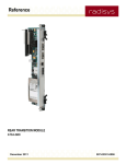
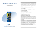
Figure 1 illustrates the CPM’s major functional blocks. Chapter 4, Components and Subsystems, on page 31 contains detailed information about how the CPM functions.
Figure 1. CPM functional blocks
Front I/O
(2) USB 2.0
(1) RS-232 (RJ-45)
(2) 10/100/1000 Ethernet (RJ-45)
Reset Switch
ATCA LEDs
AMC.3 – SAS (Port 3)
0
8
;
AMC.3 – SAS/SATA (Port 2)
AMC.2 - GbE (Ports 0, 1, 8, 9)
)
5
AMC.1 – PCIe (Ports 4-7)
2 AMC
TCLK B/D
1
FCLKA
Update Fast Path (Port 12)
7
Update Slow Path (Port 13)
RTM Control (Port 15)
RTM I/O (Ports 17-20)
,
2
x4
eUSB
Flash
to CLK3 in Zone 2
PCIe 100MHz
(to RTM)
RTM Link
SPI
Flash
SPI
Flash
LPC
SATA USB 2.0
(to Update Channel)
=
2
1
(
eUSB
Flash
ICH10R
CPU
Complex
FPGA
(to IPMC)
x2
ESI
(to RTM)
SATA
SIO
RS-232
82576EB
GbE
Front/RTM
x2
TPM
(to IPMC)
(to Front Panel) COMux
CPLD
x4
(to RTM)
(from AMC)
x4
x4
(to AMC)
x4
9
/
3
5
'
,
0
0
14
DDR3
800MHz/1066MHz Ch. C
x8
[10] [9]
9
/
3
5
'
,
0
0
[5:6]
Ch. B
9
/
3
5
'
,
0
0
DMI [4] [7]
Xeon CPU
QPI
5.86 GT/s
5520 IOH
[3]
x4
1000 Base-BX/KX
0
8
;
82598EB
10GbE
Fabric
=
2
1
(
82576EB
GbE
BASE
Ch. A
Color Key
PCIe
Ethernet
SAS/SATA
POL
Supplies
10GBase-BX4/KX4
or
x4 1000Base-BX/KX
Per Fabric Interface
1000Base-BX/KX
LPC
(KCS) RS-232
I2C Bus 2
I2C Bus 3
I2C Bus 4 (SOL)
IPMB-L (AMC & RTM)
CLK3
Update Channels
IPMB-A
IPMC
Input
Power
IPMB-B
48V-A
48V-B
=
2
1
(
Quad-core processor with integrated memory controller
1
Quad-core processor with integrated memory controller
For central processing operations, the ATCA‐4500 uses the Intel® Xeon® 5500 series processor, and the ATCA‐4550 and ATCA‐4555 use the Intel Xeon 5600 series processor. For detailed information about the processor and memory controller, see Processor and memory controller on page 31. Memory and data storage options
The CPM provides 8 VLP DIMM sockets to support ECC memory options ranging from 1 GB to 64 GB. The CPM supports up to 64 GB of DDR3 memory when running at 800MHz, and up to 48 GB at 1066MHz. Memory storage is also provided through two banks of optional user flash memory (eUSB) that can be configured for up to 16 GB each.
The CPM can be configured with additional storage options. For details, see Memory and storage devices on page 33.
I/O capabilities
The CPM uses the Intel chipset in conjunction with the ICH10R I/O controller hub to interface with peripheral input and output devices. The CPM front panel provides:
• Two USB 2.0 compliant ports for connecting peripheral devices.
• Two 10/100/1000 copper Ethernet ports for network communications.
• One RS‐232 serial port for console operations.
Refer to Front panel LEDs, buttons, and ports on page 23 for more information about the front panel. See Backplane interfaces on page 28 for information on the backplane.
The CPM provides backplane interfaces for Base and Fabric ports, AMC ports, synchronization clocks, and the IPMB connections. Features include:
• Two GbE/10 GbE ports for the Fabric interface
• Support for quad GbE connections from the AMC to the Fabric interface. The AMC has two GbE ports for each Fabric interface channel.
The CPM also provides several I/O options through the Zone 3 interface. An optional rear transition module (RTM) provides access to SAS storage and an on‐board SAS hard disk drive. For information about RTM features, refer to the ATCA‐5400 RTM Reference.
15
1
Product Overview
Hardware management
The function and operation of the CPM hardware management subsystem is controlled by the Intelligent Platform Management Controller (IPMC). The IPMC manages these functions:
• Local hardware sensors for the CPM and RTM.
• Electronic keying support for Fabric interface, synchronization clocks, and update channels.
• System event log (SEL)
• Remote executable flash and microcontroller software upgrade support.
• Serial‐over‐LAN (SOL) support via the Base Ethernet controller or the front/rear Ethernet controller.
• Local output actuators
• IPMBs
• Serial EEPROM
• AMC and RTM control and management.
For more information, refer to Chapter 5, Hardware Management, on page 49.
16
INSTALLING MEMORY MODULES
2
Supported DIMM combinations
There are eight DIMM sockets (dual inline memory modules) on the CPM for installing VLP DDR3 registered ECC DIMMs. In Figure 2, the sockets are grouped into three channels. When installing DIMMs, begin by populating the channels that are farthest from the CPU. Balance DIMMs across the channels by populating slot 0 for each channel first, followed by slot 1, and then slot 2. The preferred memory configurations are listed in Table 1.
The CPU’s integrated memory controller supports up to three channels of DDR3 DIMMs, using 64 data bits and 8 ECC bits per channel. Each channel supports up to three DIMMs (single, dual and quad‐rank DIMMs) and supports DRAM speeds of 800MHz and 1066MHz with the following limitations:
• Three DIMMs per channel only support single and dual‐rank DIMMs at 800 MHz. • At 1066 MHz, only two DIMMs per channel are allowed for single and dual‐rank. • For quad‐rank, only one DIMM per channel is allowed at any speed.
Note: Optimum memory performance is only achieved when DIMMs of identical rank and size are installed equally in all three channels.
Figure 2. DIMM slots and channels
Channel A
Channel B
Channel C
CPM Front Panel
CPU
C0
C1
B0
B1
B2
A0
A1
A2
Table 1. Preferred memory population options
Number of DIMMs
3
3
6
6
8
a
DIMM Type
Single-rank
Dual-rank
Single-rank
Dual-rank
Dual-rank
Channels Populated
C0, B0, A0
C0, B0, A0
C0, C1, B0, B1, A0, A1
C0, C1, B0, B1, A0, A1
C0, C1, B0, B1, B2, A0, A1, A2a
This configuration yields maximum memory.
17
2
Installing Memory Modules
Mismatched DIMM combinations and SEL error events
A memory initialization error occurs if memory channels are not consistently populated from the lowest‐numbered slot to the highest‐numbered slot. Using Channel A as an example in Figure 2 on page 17, slot A0 should be populated first, then A1 and then A2. The error occurs if Channel A only has A0 populated and Channel B only has B1 populated.
When the CPM boots it performs memory initialization and validates the DIMM slot population. If a mismatched (incorrect) combination of DIMMs is detected the BIOS logs a SEL event. See Table 23 on page 78 for details on the Memory Errors sensor.
Mismatched memory configurations must be corrected by following the recommendations in Supported DIMM combinations on page 17.
Installing DIMMs
Installing DIMMs consists of removing the DIMM cover, installing the DIMM memory cards, replacing the DIMM cover, and re‐installing the CPM in the shelf. The following sections detail these procedures.
WARNING! Observe appropriate ESD precautions when performing the procedures in this
chapter (see Electrostatic discharge on page 8).
Removing the DIMM cover
1. Place the CPM on a flat, static‐free surface.
2. Remove the two screws holding the DIMM cover in place (see Figure 3 on page 18).
3. Lift off the DIMM cover.
Figure 3. DIMM cover
Screws
DIMM
cover
18
Installing the memory cards
2
Installing the memory cards
1. Open the DIMM socket ejector latches by pushing them outward. See Figure 4.
Figure 4. DIMM sockets
Ejector latch
DIMM socket
2. The DIMMs are keyed so they can be inserted in only one way. Hold the DIMM by the edges, align the slot (keyway) of the DIMM with the tab molded in the base of the socket, and push the card down firmly into the socket. The ejector latches close and the DIMM clicks into place when it is firmly seated.
3. Insert the other DIMMs in the same manner, remembering to fill the corresponding DIMM slot for correct channel operation.
4. Screw the DIMM cover plate back into place.
5. Install the CPM in the shelf, then power up the module and check the BIOS screens to verify all memory is working. See Testing installed memory on page 20.
Replacing DIMMs
These instructions assume the CPM has been removed from the shelf and the DIMM cover has been removed. See Removing the DIMM cover on page 18.
WARNING! Observe appropriate ESD precautions when performing these procedures (see
Electrostatic discharge on page 8).
1. Determine which DIMMs to remove (see the previous discussion under Supported DIMM combinations).
2. Press outward on the DIMM socket ejector latches to pop out a DIMM, as shown in Figure 4 on page 19. Hold the DIMM by the edges and remove it. Remove the other DIMMs in the same manner.
3. To replace the DIMM with a new card, follow the steps under Installing the memory cards on page 19.
19
2
Installing Memory Modules
Testing installed memory
After the DIMMs are installed and the CPM is installed in the shelf, verify that the expected memory is available and the memory is valid by performing the following tests.
Verifying DIMM operation
Verify that the BIOS detects and enables all installed memory. The total memory size detected and enabled is reported in the main page of the BIOS setup menu.
If the total amount of detected memory is less than the total physical DIMM memory that is installed, check each DIMM for these conditions:
• The DIMM is incorrectly installed
• The DIMM is faulty
• The DIMM installation violates the population rule. See Mismatched DIMM combinations and SEL error events on page 18 for details about population rules.
A DIMM that is not detected or enabled properly can be identified through the BIOS setup menu (Chipset > North Bridge > DIMM info).
Running a memory test
After the DIMMs are installed, a memory test can be run from the EFI shell by executing the memtest command. The test scans all memory regions and reports any errors. Follow these steps:
1. Access the EFI shell from the BIOS setup utility by making it the first boot device, or by choosing EFI shell after selecting the Override boot source for next boot setting in the Save & Exit menu.
2. Start the memory test by entering memtest without any command arguments. The memory test loops continuously through available memory regions until the ESC key is pressed.
Help is available for memtest by entering memtest /?.
Note: Disable ECC error correction in the BIOS setup before running the memory test. This ensures maximum test accuracy and prevents the masking of hardware errors. If ECC is enabled, check the system event log for any ECC errors that may occur during the memory test.
20
Running a memory test
2
The following is an example of memtest output:
Shell> memtest
LOOP: Starting pass 1
START: Testing Memory Region 0x8000 ‐> 0x5FFFF
PASSED: 0x8000 ‐> 0x5FFFF Addressing Test (Fast)
PASSED: 0x8000 ‐> 0x5FFFF Data Test (Patterns)
PASSED: 0x8000 ‐> 0x5FFFF Addressing Test (Complex)
PASSED: 0x8000 ‐> 0x5FFFF Data Test (Walking Bits)
END: Total Error Count (All Tests) = 0.
START: Testing Memory Region 0x100000 ‐> 0xFFFFFF
PASSED: 0x100000 ‐> 0xFFFFFF Addressing Test (Fast)
PASSED: 0x100000 ‐> 0xFFFFFF Data Test (Patterns)
Note: If the system stops responding while memtest is executing it may be due to a memory failure that affects the areas of memory used for the executable code running the test.
21
2
22
Installing Memory Modules
LEDS AND EXTERNAL INTERFACES
3
This chapter describes the external indicators, switches, and ports for the CPM. Front panel LEDs, buttons, and ports
Figure 5. ATCA-4500, ATCA-4550, ATCA-4555 CPM interfaces
J30
AMC bay
J31
Dual Ethernet
RS-232
J20
Dual USB
J23
P10
23
3
LEDs and External Interfaces
The CPM has a metal front panel that serves as an EMI/RFI barrier and provides access to front panel ports and PICMG 3.0 required functions. As shown in Figure 6 on page 25, the front panel includes:
• Status LEDs
• One AMC bay
• Dual USB connector
• Dual 1000Base‐T Ethernet connector (two RJ‐45)
• An RS‐232 serial port (RJ‐45)
• A recessed reset switch
• Top and bottom ejector handles, with a hot swap switch in the bottom handle
• Top and bottom thumbscrews that secure the CPM to the shelf
Important: RadiSys requires the use of shielded cables for both serial and Ethernet port connections to minimize the possibility of issues related to external electromagnetic interference (EMI). Ethernet cables should be double‐shielded Cat 5. To comply with GR‐1089‐CORE criteria, if cables are connected to both front panel Ethernet connectors then all cables must be shielded.
24
Front panel LEDs, buttons, and ports
3
Figure 6. ATCA-4500, ATCA-4550, ATCA-4555 CPM front panel features
Thumbscrew
Ejector latch
AMC bay
Status LEDs
Ethernet port A
Ethernet port B
Serial console port
USB port 0
USB port 1
Reset button
Status LED
Ejector latch
Thumbscrew
25
3
LEDs and External Interfaces
Front panel LEDs
Table 2 describes the front panel status and activity LEDs. Table 2. Front panel LEDs
Label
LED ID
Definition
Color
OOS
LED 1
Out of service Amber or
red a
LED states
Controlled by the IPMC or the user. b
Default behavior:
• Default LED color is set by the IPMC
• Always OFF, except for the following situation:
• Persistent blink when both active and backup IPMC
application images are invalid or corrupted.
PWR
LED 2
Power
Green
Indicates whether CPM power supplies are within
tolerance. The possible states are:
• Green: All power supplies initially good, and power has
not been removed.
• Off: Module not powered on.
APP
LED 3
Application
defined
Amber b
Controlled by the IPMC, with functionality defined by the
system implementer.b
By default, this LED is off.
H/S
H/S
Hot swap
status
Blue
Controlled by the IPMC with these possible states:
• Long blink: Activating the module after insertion.
• Short blink: Preparing for hot swap.
• Solid: Ready for hot swap.
• Off: No hot swap activity in progress.
a
b
The user application can select the LED color using the Set FRU LED State IPMI command. Only red or amber can
be selected for the OOS LED.
The user application can control LED color and illumination using the Set FRU LED State IPMI command. LED
illumination can be turned on or off, the LED can be configured to blink, or the lamp test function can be enabled.
To use the command, specify the FRU ID, LED ID (which is “1” for the OOS LED), LED function, LED on duration,
and illumination color. Command usage is described in the PICMG specification, FRU LED Control commands,
section 3.2.5.6.
The IPMC uses GPIO pins to control the hot swap and power LEDs. The IPMC supplies default states for the LEDs and responds to sensor readings, GPIO inputs, and IPMI commands from other entities to change LED states.
Front panel connectors
USB 2.0 connectors
The USB interface on the front panel is a dual‐port stacked connector. USB peripheral devices, such as CD‐ROM drives or USB storage, can be connected to these ports using a standard USB 2.0 cable.
26
AMC bay
3
Serial RS-232 connector
An external computer can be attached to the CPM by connecting a shielded RJ‐45 cable to the computer and the front panel RS‐232 serial port. A shielded cable is required to minimize the possibility of issues related to external electromagnetic interference (EMI). The pinout for the RS‐232 connector is shown in Table 40 on page 141.
In order to communicate with the CPM, configure the terminal emulator on the external computer to match the default settings for the CPM serial port, as listed below: • 115200 bps
• no parity
• 8 data bits
• 1 stop bit
• no flow control
For best display results, the terminal should be set to 80 columns by 25 lines.
Dual Ethernet connector
The dual Ethernet connector provides front access to two Gigabit Ethernet ports. The two ports are shared with RTM external connectors. Either just the front connectors or the RTM connectors can be enabled at the same time. For more information, refer to Configuring the front or rear Ethernet ports on page 75.
Important: RadiSys requires the use of shielded cables for Ethernet port connections to minimize the possibility of issues related to external electromagnetic interference. Ethernet cables should be double‐shielded Cat 5. To comply with GR‐1089‐CORE criteria, if cables are connected to both front panel Ethernet connectors then all cables must be shielded.
AMC bay
The CPM includes one Advanced Mezzanine Card (AMC) bay to hold an optional AMC module which slides into rails that guide it into the right‐angle AMC B+ edge connector. The bay supports mid‐sized AMCs, such as a Promentum AMC‐3202 HDD AMC. For more information about the AMC bay, see AMC bay on page 44 and AMC connector pinout on page 147.
Reset button
The front panel includes a reset switch that performs a cold reset of the CPM. A cold reset returns all registers and devices (except the IPMC) to their default state. Note that pressing the reset button does not clear sticky bits in the CPU and I/O Hub registers. Clearing sticky bits requires a powergood reset (hot swap).
The reset switch is a recessed button. To push it, use a pen, stylus, or other small pointed object.
27
3
LEDs and External Interfaces
Backplane interfaces
Backplane connector J23 is the ATCA data transport connector, which provides Zone 2 connections for two 10/100/1000BASE‐T Ethernet Base channels and two 10GBASE‐BX4 Ethernet Fabric channels. See 10‐gigabit Ethernet Fabric interface on page 41 for details about all supported Ethernet Fabric channel modes. For more information about the backplane connectors, refer to Backplane interfaces on page 142.
Backplane connector J20 provides Zone 2 connections to the synchronization clocks and the AMC update channels. For information about using update channels to connect the AMC bays on two CPMs, refer to Update channel connections to the AMC bay on page 46. For detailed information about the connector itself, refer to Zone 2 J20 connector pinout on page 144.
The CPM supports E‐Key control by describing its backplane interfaces to the Shelf Manager, as described under E‐Key control of interfaces on page 59.
The power control interface to the IPMC is through the backplane connector P10, the Zone 1 power distribution connector. Refer to Zone 1 P10 connector pinout on page 143 for details.
Alignment keys
The CPM implements the K1 and K2 alignment blocks at the top of Zone 2 and Zone 3, as required by the PICMG 3.0 specification. The Zone 2 alignment block (K1) is assigned a keying value of 11. The Zone 3 alignment block (K2) is assigned a keying value of 55.
28
Rear transition module (RTM) interface
3
Rear transition module (RTM) interface
The CPM includes the standard Zone 3 backplane interface to provide connectivity to an optional RTM, such as the ATCA‐5400. This interface consists of two connectors: J30 for common and maintenance signals, and J31 for SerDes (serialization/deserialization connectivity). For details, refer to Zone 3 J30 connector pinout and Zone 3 J31 connector pinout on page 146.
The electrical connections between the CPM and the associated RTM include:
• Switched +12V power, under the control of the IPMC
• Switched +3.3V IPMC power, under the control of the IPMC
• I2C management bus from the IPMC • Hot swap control signals
• One JTAG boundary scan interface
• Switchover signals
• RTM link signals
• Serial port
• I2C management bus, connected to I/O Controller Hub SMBus • Two Serial‐Attached‐SCSI (SAS) channels
• Two 1‐Gb Ethernet interfaces from the CPM front/rear Ethernet controller, supporting SerDes or SGMII
• Two I2C interfaces from the front/rear Ethernet controller for SGMII mode support
• Four 1‐Gb interfaces from the AMC bay, supporting SerDes or SGMII
• One I2C port from the AMC bay to provide SFP and LED control functions
• One SATA port from the I/O Controller Hub (ICH10R)
• RTM_RESET# signal used to cold reset ICs on the RTM
• Two x4 PCI Express generation 2 ports from the Intel 5520 I/O Hub (36D)
The RTM Ethernet ports are disabled when the front‐panel Ethernet ports are in use. Refer to Configuring the front or rear Ethernet ports on page 75 for more information.
A current limit switch controls the amount of current that the RTM can draw. Refer to Power consumption on page 94 for more information.
Other physical interfaces
For information about the DDR3 DIMM interface, refer to Supported DIMM combinations on page 17 and to DDR3 SDRAM on page 34.
29
3
30
LEDs and External Interfaces
COMPONENTS AND SUBSYSTEMS
4
This chapter discusses the CPM’s major components and subsystems.
Processor and memory controller
The CPM supports various versions of the Intel Xeon 5500 and 5600 series processors. The processor has an integrated memory controller and two point‐to‐point Quickpath Interconnect (QPI) interfaces for I/O Hub (IOH) and CPU connectivity. The processor cores share an 8MB cache and support SSE2, SSE3 and SSE4 streaming SIMD (Single Instruction, Multiple Data) extensions. The extensions enhance the performance of optimized applications like video, image processing, and media compression. Note: The CPM does not use the CPU’s turbo boost feature.
The CPU includes the Execute Disable Bit, 64‐bit technology, Intel SpeedStep®, virtualization technology and simultaneous multi‐threading. The processor also features a loop stream detector that greatly increases loop execution speed. Table 3 and Table 4 provide the various processor specifications. Table 3. CPU power specifications
Processor
Core Frequency
Core voltage
Temp max TJ
L5518 60W (for ATCA-4500)
L5638 60W (for ATCA-4550)
E5645 80W (for ATCA-4555)
2.13GHz
2.00GHz
2.40 GHz
0.75V - 1.35V
1.0V - 1.5V
0.75V - 1.35V
70°C
70°C
76.2°C
Thermal design power
(TDP)
60 W
60 W
80 W
Table 4. CPU bus specifications
Processor
L5518 60W (for ATCA-4500)
L5638 60W (for ATCA-4550)
E5645 80W (for ATCA-4555)
Cores
4
6
6
Threads
8
12
12
Core frequency
2.13GHz
2.00 GHz
2.40 GHz
QPI speed
5.86 GT/s
5.86 GT/s
5.86 GT/s
DDR3 speed
800/1066 MHz
800/1066/1333 MHz
800/1066/1333 MHz
Cache size
8MB
12MB
12 MB
Adaptive thermal monitor for processor protection
The CPU case temperature must remain within the specified operating range in order to maintain reliability over the life of the processor. The CPU includes an adaptive thermal monitor (ATM) to help control the processor temperature. The ATM selects between voltage and frequency control (Intel SpeedStep®) and internal clock modulation to reduce processor power and to activate the thermal control circuitry.
31
4
Components and Subsystems
The CPU includes a single digital thermal sensor (DTS) that continuously measures the temperature at each processing core and provides processor die temperature information that represents the worst case temperature for all cores. The DTS data represents the difference between the current die temperature and the temperature at which the ATM activates the thermal control circuitry. The IPMC accesses DTS information through the platform environmental control interface (PECI).
For more information on the temperature sensors, refer to Managed sensors on page 104.
Integrated memory controller
The integrated CPU memory controller supports up to three independent channels of DDR3 DIMMs, using 64 data bits and 8 ECC bits per channel. When running at 800MHz, the CPM supports up to 64 GB of DDR3 memory. At 1066 MHz, it supports up to 48 GB. Refer to DDR3 SDRAM on page 34 for more information about the DIMMs and to Supported DIMM combinations on page 17 for more information about CPM DIMM configurations.
Memory modes
The memory controller operates in independent mode. Independent mode allows the memory controller to interleave the memory map across all three channels, resulting in the highest level of performance. In independent mode, DIMMs can be placed in any of the three channels and there are no matching requirements for rank or DIMM speed. A burst‐length of 8 is used. Note: • Maximum performance is achieved only when the DIMMs are identically populated across the three channels.
• The CPM only supports registered ECC DDR3 DIMMs; it does not support unbuffered DIMMs (with or without ECC).
DRAM temperature control
The CPU can influence the DRAM temperature by reducing the memory channel frequency (throttling). The CPM triggers a frequency decrease by asserting a DDR_THERM# input to the CPU whenever the DIMM temperature gets too high (implemented by wiring together the EVENT# pins from each DIMM).
32
Quick path interconnect
4
2x refresh mode
The CPU doubles the refresh rate to the memory channels to better preserve the data when the DRAM is operating at elevated temperatures. The DRAM components have two temperature limits: T32 and T64. T32 is the temperature limit for a 1x refresh rate. T64 is the upper DRAM temperature limit when operating in 2x refresh mode. When T64 is exceeded, an SMI (system manager interrupt) is generated because the DRAM is operating out of specification. For a typical DDR3 DRAM component, T32 is 85°C and T64 is 95°C.
The double refresh rate can be disabled by changing the setting to 1x refresh in the BIOS.
Quick path interconnect
The CPU includes two point‐to‐point Intel QuickPath interconnect interfaces (QPI) for communication between the CPU and the I/O hub. However, the CPM uses only one QPI interface from the CPU (QPI port 1). The QPI interface is 20 lanes wide under full operation. With its integrated memory controller, the CPU incorporates the QPI caching agents for maintaining cache coherence as well as the home agents for managing access to memory regions. Data of any width is converted to packets and then sent serially over the QPI link (see Table 4).
Memory and storage devices
The CPM provides the following memory devices:
• Sockets for installing DDR3 DIMMs. See DDR3 SDRAM for more information.
• Two 16MB (redundant) SPI flash memory chips dedicated to BIOS and boot operations (see Redundant boot flash).
• Pluggable eUSB modules for user flash memory (see Redundant user flash). These devices provide additional storage options for the CPM:
• a SFF flash drive on the AMC
• a local SFF SAS hard disk drive on the RTM, which includes a storage controller for a hardware‐based redundant array of inexpensive hard disk drives (RAID)
• iSCSI storage over both the Base and Fabric interfaces
33
4
Components and Subsystems
DDR3 SDRAM
The CPM has 8 VLP DIMM sockets for registered DDR3 SDRAM modules. These DIMM sockets are grouped into three independent channels. Two of the channels (A and B) can hold up to three DIMMs, while the third channel (C) only holds up to two DIMMs: • Three DIMMs per channel (A and B) is only supported for single‐ and dual‐rank DIMMs running at 800 MHz. • At 1066 MHz, only two DIMMs per channel are allowed for single and dual‐rank. • For quad‐ranked DIMMs, only two DIMMs per channel are allowed at any speed. See Table 1 on page 17 for a list of preferred memory configurations.
For more information on supported SDRAM configurations, refer to Supported DIMM combinations on page 17. For information regarding memory operating modes, refer to the discussion under Integrated memory controller on page 32.
Redundant boot flash
Two 16MB Serial Peripheral Interface (SPI) flash memory devices are used on the CPM to provide a redundant boot function.
SPI flash selection
The primary SPI flash is selected when the CPM is powered up. If the CFD watchdog timer expires, the IPMC powers down the CPM, selects the secondary SPI flash, then powers up the CPM. For more information on the CFD watchdog, refer to Corrupt flash detection watchdog on page 58.
Tip: The flash device selection for the next boot can be overridden by setting an option on the BIOS boot menu.
SPI flash programming
The SPI flash can be programmed by booting into the EFI shell and using an EFI reflash utility and a USB flash disk. Standard Linux and DOS‐based reflash utilities can also be used for programming the flash. Boot block protection
The CPM uses a hardware jumper to control the write‐protect signal to the SPI flash in order to protect the boot block. When the jumper is installed, the boot block is write protected. When the jumper is not installed, the boot block is write‐enabled. Refer to Jumper settings on page 152 for more information. 34
Redundant user flash
4
Redundant user flash
The CPM optionally includes two banks of user flash memory with up to 16 GB storage capacity for each bank. Each redundant flash bank can be used to store an operating system and application image, allowing it to function as a boot device.
Each user flash consists of an embedded universal serial bus (eUSB) flash module. The eUSB flash memory has a small form factor, low power consumption, and fast access time. The I/O controller hub uses standard USB 2.0 connections to communicate with the user flash.
Note: The CPM includes a write‐protection jumper for each memory bank. Refer to Jumper settings on page 152 for more information.
Access to storage devices from Linux
The CPM storage devices are accessible from Linux as formattable media, depending on your operating system configuration.
Device type naming
The Linux device type is determined by the physical device type installed. The Linux file system names may be /dev/sd<drive><partition> for SCSI devices or /dev/
hd<drive><partition> for hard disks. USB and SAS devices are considered SCSI devices (/
dev/sd<drive><partition>).
Order of device discovery and naming
The order in which Linux discovers the storage devices is the order that it assigns them alphabetical names, starting with the suffix “a”. For example, the first SCSI device discovered is named /dev/sda, and the second is named /dev/sdb.
Identifying the assigned name for a specific device
To identify the drive name for a specific device, use the Linux command:
cat /proc/partitions
Look in the results for a drive size that closely matches the device. To identify the SCSI devices by device model, use the command:
cat /proc/scsi/scsi
The devices are listed in order, starting with /dev/sda.
35
4
Components and Subsystems
I/O hub to PCI Express devices
The CPM includes an Intel 5520 chipset I/O hub (IOH) that provides the bridge between the PCI Express (PCIe) devices in the system and the CPU QPI interface. The IOH provides 36 PCIe ports capable of Gen1 (2.5 GT/s) and Gen2 (5 GT/s) speeds. Table 5 shows the PCI Express port mapping. Table 5. PCI Express port mapping
Port
1
2
3
4
5
6
7
8
9
10
Port Width
x2
x2
x4
x4
x8
PCI Express Peripheral
Not used
Not used
Base Ethernet controller
RTM 0
10 Gigabit Fabric Ethernet controller
PCIe Type
Gen 1
Gen 2 capable
Gen 1
x4
x4
x4
x4
RTM 1
Not used
AMC bay
Front/rear Ethernet controller
Gen 1 and Gen 2 capable
Gen 1
Gen 2 capable
Gen 1
I/O controller hub (south bridge)
The CPM uses the Intel ICH10R I/O controller hub (ICH) to communicate with peripheral input and output devices. Its features include:
• Up to six SATA ports with data transfer rates up to 3.0 Gbps and an integrated advanced host controller interface (AHCI) controller.
• Two USB host controllers, providing up to twelve USB 2.0 ports
• An LPC bridge
• An SMBus 2.0 controller
• An enhanced DMA controller (two cascaded 8237 DMA controllers)
• An interrupt controller that supports: • Up to eight PCI interrupt pins
• PCI2.3 message signaled interrupts
• Two cascaded 82C59 with 15 interrupts
• An integrated I/O APIC capability with 24 interrupts
• Processor system bus interrupt delivery
• Real‐time clock (RTC) circuitry
36
USB controller
4
USB controller
The ICH contains two universal host controller interface (UHCI) controllers and two enhanced controller host interface (EHCI) controllers that share the same set of pins. Each pair of controllers provides up to twelve USB 1.1 or USB 2.0 ports. Each EHCI port allows data transfers up to 480 Mb/s and reports over‐current status back to the ICH. The CPM provides the five ports listed in Table 6 when configured for EHCI (USB 2.0):
Table 6. USB 2.0 ports
Port Number
0
1
2
3
4
Port Location
Front panel, upper USB port
Front panel, lower USB port
No external port connections
RTM USB port
Notes
Refer to Front panel connectors on page 26 for additional
information.
USB NAND flash A and B. User flash is discussed under
Redundant user flash.
Refer to Rear transition module (RTM) interface on page 29.
SATA controller
The ICH includes two SATA host controllers that support data transfer rates of up to 3.0 Gbps. Communication over the SATA bus can operate in one of two different modes, depending on operating system requirements:
• In native mode, both controllers are used to implement up to six SATA ports. Ports 0 ‐ 3 are handled by the first controller and ports 4 ‐ 5 are handled by the second controller. • In legacy mode, only ports 0 ‐ 3 are available from the first controller. For information about SAS/SATA switching control, refer to SAS and SATA on page 39.
SPI bus
The ICH uses a serial peripheral interface (SPI) bus for communication with the two boot flash devices. This connection is discussed in more detail under Redundant boot flash.
LPC bridge
The ICH enables communication between the CPU and low‐bandwidth peripherals by providing a low pin count (LPC) bridge connection to the following devices:
• Super I/O (see Super I/O chip)
• CPU complex FPGA (see CPU complex FPGA)
• IPMC (see Intelligent Platform Management Controller)
The LPC bridge implements all of the cycles described in the Intel Low Pin Count Interface Specification, Revision 1.1. 37
4
Components and Subsystems
Real-time clock
The ICH includes an integrated real‐time clock (RTC) that keeps track of the time of day and date. The RTC circuitry includes 256 bytes of capacitor‐backed CMOS RAM. The RTC is derived from a 32.768KHz crystal with the following specifications:
• Frequency tolerance @ 25°C: ± 20 ppm
• Frequency stability: maximum of ‐0.04 ppm/( °C)2
• Aging F/f (first year @ 25 °C): ± 3 ppm
• ± 20 ppm from 0‐55 °C and aging 1 ppm/year
When power is removed from the board, the time and date are maintained by an electrolytic capacitor for up to two days. When the chassis is turned on, the RTC gets power from the IPMI 3.3V power supply, which allows the capacitor to begin charging before the CPM payload power is turned on.
RTC date ranges and default initial dates
The following are valid date ranges and default initial dates that can be set in the RTC through the BIOS. Values vary based on the BIOS version.
• BIOS version 01.01.32 and below:
Valid date range: 01/01/2005 ‐ 12/31/2099
Default initial date: 01/01/2005
•
BIOS version 01.01.33 and above:
Valid date range: 01/01/1998 ‐ 12/31/2099
Default initial date: 01/01/2005
See the help section in the BIOS Setup main menu for assistance setting the date for the RTC.
SMBus controller and multiplexers
The ICH includes a SMBus 2.0‐compliant host controller, which allows the CPU to initiate communication with SMBus slave peripherals and I2C‐compatible devices. Two SMBus multiplexers give the IPMC access to the ICH slave registers and to the DIMM temperature sensors. Refer to I2C and SMBus map on page 163 for information on the devices connected to the SMBus. The slave interface allows an external master to read from or write to the ICH. Write cycles can be used to cause certain events or to pass messages. Read cycles can be used to determine the state of various status bits. The ICH’s internal host controller cannot access the internal slave interface.
38
Super I/O chip
4
The ICH SMBus consists of a transmit data path and host controller. The transmit data path provides the data flow logic needed to implement the seven different SMBus command protocols and is controlled by the host controller. The RTC clocks the ICH SMBus controller logic.
The host controller’s programming model has two segments: a PCI configuration and a system I/O mapping. All static configurations, such as the I/O base address, are configured via the PCI configuration space. Real‐time programming of the host interface is done in system I/O space.
Super I/O chip
A Winbond W83627 super I/O chip provides dual serial ports and voltage monitors to the CPU. On the CPM, the super I/O is connected to the ICH through the LPC bus and is used primarily for serial connectivity and voltage monitoring.
Both of the CPM COM ports are connected to the COMux CPLD. The serial connection to the front panel (COM 1) supports dual hardware handshaking and implements the following signals: TXD, RXD, DTR, RTS, DSR and CTS. The serial connection to the RTM (COM2) supports TXD and RXD only. Software handshaking is possible. TPM chip
The Trusted Platform Module (TPM) chip is a security key generator and a key cache management device for storing secure cryptographic keys. The TPM module is accessible through the LPC bus.
The BIOS TPM code is invoked at specific instances during POST boot execution, and provides integrity authentication during the boot process.
SAS and SATA
The SAS and SATA connections are diagrammed in Figure 7 on page 40.
SAS
An RTM such as the ATCA‐5400 is required for a SAS connection because the SAS controller is on the RTM. A SAS hard disk drive cannot be used on an installed AMC unless the RTM is present.
SATA
The SATA controller resides on the CPM, so an RTM is not required. An installed AMC can use a SATA hard disk drive, but a SAS drive is not supported for the AMC.
39
4
Components and Subsystems
Figure 7. SAS/SATA multiplexer connections
Intel
ICH10R
SATA SATA
Port 0 Port 1
AMC Bay
(SAS / SATA
HDD)
Multiplexer
SAS/SATA
Port B
Port 2
Port 3
Port A
SAS
Zone 3
Connector
J30
SATA
SAS/SATA
SATA 0
SAS 1
SAS 0
Ethernet controllers and interfaces
Gigabit Ethernet interfaces
The CPM uses two dual gigabit Ethernet controllers (Intel 82576EB devices) to provide four GbE ports. One controller is used for the two GbE Base interface channels, and the other is used for the front panel and RTM Ethernet ports.
Each controller has two independent network interfaces that support SerDes (serializer‐
deserializer), SGMII, or MDI (copper) protocols. Each controller is connected to a x4 PCIe port that operates at 2.5 Gbps and is capable of negotiating x2 and x1 link widths.
The Ethernet controllers provide virtualization support including PCI‐SIG single‐root I/O virtualization, VMDq2 support for up to 8 virtual machines and 16 TX and RX queues. A system management bus (SMBus) interface supports pass‐through traffic for Serial‐over‐
LAN from the IPMC. Each Ethernet controller has a private128‐KB SPI EEPROM for storing initialization data and media access control (MAC) addresses. During power up, the initial configuration information for the controllers (including management setup and SMBus addresses) is read from these EEPROMs. Refer to Overview of firmware updates on page 87 for information about updating the EEPROM software.
The controllers have two fully integrated gigabit Ethernet MAC and PHY (physical layer) ports. These devices use the PCI Express architecture (revision 1.0a).
40
10-gigabit Ethernet Fabric interface
4
Base Interface
The Base controller is configured for MDI (copper), providing 1000Base‐T, 100‐Base‐TX, and 10Base‐T support. The Base controller is connected to the BASE 1 and BASE 2 backplane ports, and the controller is connected with a x4 link to PCIe port 3 on the I/O hub. The EEPROM for the Base controller enables pass‐through mode via the SMBus, which allows the IPMC to implement serial‐over‐LAN on either base port.
Front panel and RTM Ethernet interfaces
One of the GbE controllers is used to implement dual Ethernet ports to either the front panel or the RTM rear panel. The MDI (copper) ports are connected to the front panel interface for 1000Base‐T, 100‐Base‐TX and 10Base‐T support. The SerDes signals are routed through the Zone 3 connector to two SFP transceivers on the RTM. Selection of front or rear ports is controlled through a BIOS menu (see Configuring the front or rear Ethernet ports on page 75).
The front/rear GbE controller is connected with a x4 link to PCIe port 10 on the I/O hub. The EEPROM for the front /rear controller enables pass‐through mode over the SMBus to allow the IPMC to implement serial‐over‐LAN on either port. Refer to Serial‐over‐LAN on page 65 for more information.
10-gigabit Ethernet Fabric interface
The CPM uses an Intel 82598EB controller to provide two 10‐GbE port connections to the Fabric interface channels. The 10‐GbE controller is connected to a x8 PCIe port that is PCIe 1.1 compliant. A private 128‐KB EEPROM stores initialization data and MAC addresses. The 10‐GbE controller includes two independent XAUI ports that support the following standard Ethernet interfaces:
• 10GBASE‐KX4
• 1000BASE‐KX (IEEE 802.3ap)
• 10GBASE‐CX4 (IEEE 802.3ak)
Each port also contains a SerDes interface to support 1000BASE‐SX/LX (optical fiber) and 1000BASE‐BX for gigabit backplane applications. Auto negotiation (as specified by IEEE 802.3ap Clause 73) is also supported.
Fabric interface
The CPM provides multiple connectivity options to Fabric channels 1 and 2. The multiplexer option for Fabric channels 1 and 2 connects either the 10‐GbE controller for 10‐Gb Fabric connections or the AMC bay to the backplace. The Fabric connections are determined by the interface E‐Keying (see E‐Key control of interfaces on page 59). The default configuration is to route Fabric channels 1 and 2 to the 10‐GbE controller as 10GBase‐BX4/1000Base‐BX (see Figure 8 on page 43).
41
4
Components and Subsystems
Depending on the interface E‐Keying, Fabric channel 1 is configured as one of these options: • A 10GBase‐BX4 (or KX4) connected to Port 0 of the 10‐GbE controller • Three 1000Base‐BX (or KX) links. One link is connected to Port 0 of the 10‐GbE controller, and the two remaining links are connected to AMC Ports 0 and 8. Similarly, Fabric Channel 2 is configured as one of these options: • A 10GBase‐BX4 (or KX4) connected to Port 1 of the 10‐GbE controller • Three 1000Base‐BX (or KX) links. One link is connected to Port 1 of the 10‐GbE controller, and the two remaining links are connected to AMC Ports 1 and 9. 42
10-gigabit Ethernet Fabric interface
4
Figure 8. Ethernet Fabric interface
10GbE Fabric Configuration
Intel 82598 EB
(10GbE) Port 0
Port 1
Zone 2
Connector
J23
Multiplexer
10G BASE-KX4
Port B[0:3]
10G BASE-BX4/KX4
Fabric Channel 1
[0]
[1]
[2]
[3]
10G BASE-BX4/KX4
Fabric Channel 2
[0]
[1]
[2]
[3]
10G BASE-KX4
Multiplexer
Port B[0:3]
GbE Fabric Configuration
Intel 82598 EB
(10GbE) Port 0
Port 1
Multiplexer
1000 Base-KX
Zone 2
Connector
J23
3x 1000 Base-BX/KX
Port B[0]
Fabric Channel 1
[0]
[1]
[2]
1000 Base-KX
Port A[1]
Port A[2]
AMC Bay
(1GbE)
Port 0
Port 8
1000 Base-BX/KX
1000 Base-BX/KX
Multiplexer
Port B[0]
Port 1
Port 9
1000 Base-BX/KX
1000 Base-BX/KX
Port A[1]
Port A[2]
3x 1000 Base-BX/KX
Fabric Channel 2
[0]
[1]
[2]
43
4
Components and Subsystems
AMC bay
The CPM supports one Advanced Mezzanine Card (AMC) bay that is compliant with the AMC.0, AMC.1 (PCI Express), AMC.2 (Ethernet), and AMC.3 (Storage) PICMG specifications. The bay supports mid‐size modules and the RadiSys HDD‐AMC. The bay can provide up to the AMC.0 maximum of 80W, but the total power consumption allowed is 40W. The AMC bay has basic and extended connector sections. The basic section consists of the clocks, dual GbE (SerDes) ports, SAS/SATA ports, and a x4 PCI Express port. The extended section includes two additional GbE ports, an update channel port, RTM control, and RTM extended I/O. Table 7 shows the port mapping for the AMC bay, and Table 8 describes AMC port interfaces. Also refer to AMC connector pinout in Appendix C for connection details. Table 7. AMC port mapping
Basic
connector
Extended
connector
44
Port
TCLKA
TCLKB
TCLKC
TCLKD
FCLKA
0
1
2
3
4
5
6
7
8
9
10
11
12
13
14
15
16
17
18
19
20
Function
Telecom Clocks (AMC.0).
TCLKA and TCLKC are not supported.
Fabric Clock (AMC.0/AMC.1)
GbE (AMC.2 Type E2)
SAS/SATA to RTM/ICH Mux (AMC.3)
SAS to RTM (AMC.3)
Type 4 x4 PCI Express (AMC.1)
GbE (AMC.2 Type 2)
(no connect)
Fast Path Update Channel
Slow Path Update Channel
(no connect)
Rear Transition Module Control
(TCLKD above)
Rear Transition Module access (AMC.0)
AMC bay
4
The CPM’s IPMC provides intelligent platform management (IPM) connectivity between the backplane IPMB and the AMC’s local IPMB (IPMB‐L). Depending on the software involved, the AMC bay may be addressed in any of the following ways:
PICMG 3.0 commands
BIOS setup screens
AMC.0 site number
IPMB-L address
AMC bay
FRU 1
Slot 1
Site 5
0x7A
The Shelf Manager refers to the AMC as bay 5, corresponding to the AMC.0 site number. Shelf Manager alarms pertaining to the AMC will use this number, and the HPI resource IDs will refer to site 5. Other shelf managers may refer to the AMCs by their AMC.0 site numbers or FRU numbers.
See the Advanced Mezzanine Card Installation Guide for installation instructions.
Table 8. AMC port interfaces
Identity
Synchronization TCLKA
Synchronization TCLKB
Synchronization TCLKC
Synchronization TCLKD
Fabric FCLKA
Common option Fabric ports 0 and 1
Common option Fabric ports 2 and 3
Fat Pipes Fabric ports 4, 5, 6, and 7
Fat Pipes Fabric ports 8 and 9
Fat Pipes Fabric ports 10 and 11
Extended options Fabric port 12
Extended options Fabric port 13
Extended options Fabric port 14
Function
Not supported.
The AMC can drive synchronization TCLKB to the CLK3 clock selection circuitry on the CPM.
Not supported.
The AMC can drive synchronization TCLKD to the CLK3 clock selection circuitry on the CPM.
Fabric FCLKA is driven to the AMC bay by the 100-MHz PCIe clock generator on the CPM.
Ports 0 and 1 of the AMC bay connect 1000Base-BX Ethernet to the Fabric multiplexer on the CPM.
Ports 2 connects to the SAS multiplexer. The Port 2 connection switches between SAS channel 0
from the RTM and SATA channel 0 from the ICH. The Port 3 connection passes directly to SAS
channel 1 on the RTM. These interconnections are compliant with the PICMG AMC.3 Storage AMC
specification.
Ports 4 through 7 of the AMC bay connect to IOH PCIe port 9 on CPM with a x4 link. These
interconnections are compliant with the PICMG AMC.1 PCI Express AMC specification (Type 4).
Ports 8 and 9 of the AMC bay connect 1000Base-BX Ethernet to the Fabric multiplexer on the CPM.
Ports 10 and 11 are unused on CPM.
Port 12 of the AMC bay is connected to the update channel through the equalizer, and allows up to
3.2 Gbps throughput (spare SAS multiplexer ports are used for this task). This provides direct
interconnection between AMC modules on redundant CPM carrier blades.
The E-Keying function is provided by the IPMC, which controls the enabling over an I2C bus.
Port 13 of the AMC bay is dedicated to a non-standard “slow path” update channel. The connection
is used for single-ended general-purpose I/O (GPIO) signals.
The E-Keying function is provided by the IPMC on the CPM, which controls the enable pins of the
buffers using GPOs. The signals on Port 13 are non-LVDS, and therefore must power up disabled
until E-keying enables them.
Port 14 is unused on CPM.
45
4
Components and Subsystems
Table 8. AMC port interfaces (continued)
Identity
Extended options Fabric port 15
Function
Port 15 of the AMC bay connects through the Zone 3 J30 connector to the RTM. These
interconnections are to provide an I2C bus from the AMC module to the RTM for SFP and LED
control. They also provide a serial port for RTM access to the AMC for debug.
Per the AMC.0 specification, AMC modules are required to power up with their ports disabled if the
signal levels used are non-LVDS. This is the case for the I2C interface and its pull-ups on the AMC
module. The RTM must also have an I2C bus isolator. The TTL-level serial port signals on the AMC
must also power up disabled.
Extended options Fabric ports 17, 18,
19, and 20
The E-Keying function is provided by software on the CPM's IPMC and the AMC module's MMC
(module management controller) working together to determine whether the ports are enabled. No
hardware buffer is provided for the port on CPM.
Ports 17, 18, 19 and 20 connect through the Zone 3 J31 connector to the RTM. These
interconnections are to provide four 1.25 Gbps differential SerDes or SGMII channels between the
AMC module and the RTM.
Per the AMC.0 specification, AMC modules are required to power up with their ports disabled if the
signal levels used are non-LVDS. The E-Keying function is provided by software on the CPM's
IPMC and the AMC module's MMC working together to determine whether the ports are enabled.
No hardware buffers are provided for the ports on CPM.
Update channel connections to the AMC bay
The update channel on the backplane has both fast (channel 0) and slow (channel 4) connections to the AMC bay. Both update channels are used to connect two CPMs (installed in chassis slots linked by the PICMG update channel). Refer to the entries for AMC ports 12 and 13 in Table 8 for a functional description of the update channels.
The slow path update channel (AMC port 13) provides a means to pass relatively slow data between redundant AMC modules on different CPMs, as illustrated in Figure 9.
Figure 9. AMC bay slow path update channel
CPM
AMC
CPU
Port 13
GPO1
GPO2
GPI1 or INT1
GPI2 or INT2
MMC
RX0+
RX0-
RX0+
RX0-
TX0+
TX0-
TX0+
TX0-
E-Key
Port 13
AMC
GPO1
GPO2
IPMC
E-Key
IPMC
CPU
GPI1 or INT1
GPI2 or INT2
E-Key
E-Key
46
CPM
Backplane
MMC
Update channel connections to the AMC bay
4
The connections to Port 13 of each AMC bay are used for single‐ended general‐purpose I/
O (GPIO) signals. The signals on Port 13 power up disabled on both the AMC and the CPM, and are E‐Keyed. The E‐Keying function is provided by the IPMC on the CPM and the MMC on the AMC modules. Each controls the enable pins of their respective buffers with GPO pins.
If an AMC module chooses to use Port 13, it must drive GPO outputs on the AMC‐side TX+ and TX‐ pins. The corresponding carrier‐side RX+ and RX‐ signals are applied to the input of the redundant CPM and AMC. The buffers drive the carrier‐side TX+ and TX‐ pins with signals received from the redundant CPM. The AMC module receives these signals on its RX+ and RX‐ pins, and can either connect them to GPI inputs or interrupt inputs. The fast path update channel is illustrated in Figure 10.
Figure 10. AMC bay fast path update channel
CPM
Port A[0]
Port B[0]
AMC
Backplane
PM8380_3
Zone 2
Connector
J20
Port A[1]
Port A[2]
Port 12
Update
Channel 0
Port A[3]
I2C
IPMC
I2C (Bus 3)
CPM
Zone 2
Connector
J20
AMC
Buffer
Port 12
Update
Channel 0
47
4
Components and Subsystems
Intelligent Platform Management Controller
The Intelligent Platform Management Controller (IPMC) monitors the health of the system and manages the CPM hardware by controlling power to the CPM payload, managing the sensors, using E‐Keys to enable ports, performing CPM resets, and executing IPMI commands. The IPMC consists of a microcontroller (a Renesas H8S/2166 device), an IPMC FPGA, and nonvolatile RAM. For more information about the IPMC, refer to Chapter 5, Hardware Management, on page 49.
CPU complex FPGA
The CPU complex FPGA provides the legacy southbridge functions required by the CPM board and the functions used by legacy operating systems. CPU complex FPGA features include: • Watchdog timers (see IPMC watchdog on page 58)
• Support for Ethernet controller LEDs on the front panel
• Transfer of RTM status and alarm signals over the RTM‐link bus
• Additional glue logic
Access to most of the status and control functions are provided by a register file internal to the FPGA. The register file can be accessed by the LPC bus, by the IPMI SMBus, or by the ICH SMBus. Access to the registers is symmetrical; all of the busses have equal access to the internal registers of the FPGA for both reading and writing.
48
HARDWARE MANAGEMENT
5
The hardware management subsystem includes the Intelligent Platform Management Controller (IPMC), the managed sensors, and the communication interfaces to external entities such as the Shelf Manager. The IPMC controls the hardware management subsystem by enabling payload power and ports, detecting component hardware states, initiating resets, and monitoring managed sensors.
The CPM’s hardware management system complies with the Intelligent Platform Management Interface (IPMI) 1.5 specification, which defines a set of common interfaces for managing the system and for monitoring system health. The IPMC (which is independent from the CPU) runs the IPMI firmware. This allows administrators to manage a system remotely even in the absence of operating system or system management software. Figure 11 shows the functional blocks making up the hardware management subsystem. Figure 11. Hardware management subsystem block diagram
Payload Processor
Complex
AMC with MMC
LPC Bus
IPMB-L
[I2C Bus 5]
RTM with MMC
IPMC
[I2C Bus 3]
MUX
SPD DIMM
Temperature
Sensors
H8
2166
Watchdog
[I2C Bus 1]
IPMC FPGA
[I2C Bus 0]
MUX
[I2C Bus 4]
Ethernet
Controllers
(Serial over LAN)
IPMB 1
E-Keying
Logic &
Controllers
(SAS/SATA
& Fabric
Muxes)
IPMB 0
ICH10 SMBus
[I2C Bus 2]
EEPROM, CPU Complex FPGA,
PECI, Local Hardware
(Temperature & Voltage)
Sensors
49
5
Hardware Management
IPMC description
The hardware management system of the CPM is controlled by an IPMC, which comprises a microcontroller, an IPMC FPGA, and EEPROMs for IPMC data storage. The IPMC interacts with the CPM’s CPU and the Shelf Manager to:
• monitor temperature, voltage, and other sensors on the CPM
• control and monitor the hot swap process for the CPM, AMC, and RTM
• interact with the Shelf Manager to implement backplane E‐Keying
• manage on‐board E‐Keying for the AMC and the RTM
• provide remote console access to the CPM payload
Using serial‐over‐LAN communications, the IPMC provides a remote user with access to the CPU serial console through the base interface. For more information, see Serial‐over‐
LAN on page 65.
The CPM's CPU communicates with the IPMC through a keyboard controller style (KCS) interface, which provides access to IPMI functions. This allows the CPU to send messages to the CPM's IPMC or to any other management controller in the shelf. For a list of the IPMI commands and details on the sensors used on the CPM, refer to Appendix B, IPMI Commands and Managed Sensors, on page 97).
IPMC microcontroller
The IPMC’s microcontroller is a Renesas H8S/2166 microcontroller. This device is a general‐purpose 32‐bit microcontroller with sixteen 16‐bit general registers. It can handle a 16‐MB linear address space; it also contains 512 KB of embedded flash and 40 KB of RAM.
The IPMC microcontroller provides the only connection between the CPM and the external ATCA shelf IPMBs. The microcontroller implements six I2C interfaces. It also supports the following interfaces, monitoring the inputs and controlling the outputs: • Digital inputs/outputs
• Analog‐to‐digital inputs
• HW‐based I2C interfaces • Serial interfaces • LPC interfaces
50
IPMC FPGA
5
IPMC FPGA
The IPMC FPGA consists of a Lattice LFXP6CF256I‐3 FPGA that is used to provide General Purpose I/O (GPIO) expansion for the IPMC. General purpose outputs (GPOs) from the IPMC FPGA are configured and reserved for power and reset controls on the CPM.
When executing E‐Key logic, the IPMC uses the IPMC FPGA to connect I2C bus 3 to the multiplexer (see E‐Key control of interfaces on page 59).
The FPGA also contains the IPMC’s hardware watchdog (see IPMC watchdog). IPMC SEEPROM
The IPMC provides 32 KB of serial EEPROM non‐volatile memory located on an internal I2C connection. The memory stores IPMI‐specific information and is divided into the partitions listed in Table 9. For details on the partition contents, see Appendix D, FRU Information, on page 153.
Table 9. SEEPROM mapping
Description
IPMC Boot Component Information
FRU Information Area
Sensor Data Record (SDR)a
Sensor Parameters
Reset Data Save Area
Local SEL Storage Area
On-board E-Key Area
Clock E-Key Area
a
Size (bytes)
(0x0010) 16
(0x0BF0) 3056
(0x0800) 2048
(0x0800) 2048
(0x3280) 12928
(0x2000) 8192
(0x0880) 2176
(0x0900) 2304
Offset range
0x0000 - 0x000F
0x0010 - 0x0BFF
0x0C00 - 0x13FF
0x1400 - 0x1BFF
0x1C00 - 0x4E7F
0x4E80 - 0x6E7F
0x6E80 - 0x76FF
0x7700 - 0x7FFF
The SDR storage area is unused in the CPM.
IPMC system event log
The CPM supports a System Event Log (SEL) for logging its own local events. The SEL space contains 8192 bytes with a 16 byte header, and each full SEL entry consumes 14 bytes of space (the two byte record ID is not stored in storage). The SEL space can store a maximum of 584 entries. If the SEL becomes full, new events are logged by overwriting the oldest entries in the SEL (FIFO implementation). SEL entries can be read by issuing the GET SEL Entry command. Issuing a Clear SEL command clears the SEL.
All events generated by sensors or the BIOS are also forwarded to the Shelf Manager for storage in the shelf's SEL.
51
5
Hardware Management
Redundant firmware images
The H8 microcontroller firmware image is composed of a single boot image and dual redundant application images, all physically stored in the single internal flash for the H8.
On reset or boot‐up of the H8, the boot image reads the Serial EEPROM of the IPMC entity to determine which H8 bank is the active bank. Next, the boot image validates the active and backup application images. If the active application image is valid, execution is transferred from the boot image to the active application image. When the active application image is invalid and the backup image is valid, execution is transferred from the boot image to the backup application image. For situations where both application images are invalid, the boot image remains in control of the IPMC, the OOS LED is toggled once every second, and the application images need to be updated.
If the IPMC detects an error while loading the application image from the active bank, the IPMC switches to the other bank and logs an event in the SEL after the other image is loaded.
For details, see the event description for the OEM HPM Event sensor on page 121.
Determining the active IPMC bank
You can use the following command to query which bank is the active IPMC application bank:
rsys‐ipmitool hpm compprop 1 192
The command returns the active bank number, as shown below. OEM Data[0] : 0x01 (= active bank number)
IPMC interface to the payload processor
The payload processor interface allows the CPU to communicate with the IPMC. The CPM implements this interface as a KCS port, which is similar to how a PC motherboard processor sends commands to a legacy PC‐compatible keyboard controller. The IPMC is connected to the payload LPC bus and responds to I/O byte addresses as a KCS interface.
The CPM uses the serial IRQ output of the IPMC to implement the messaging interrupt for the payload. The IPMC uses the serial IRQ output to generate a legacy interrupt IRQ6 to the payload processor. During use of the KCS interface by the payload processor, output buffer full (OBF) conditions generate this interrupt to the payload if the IPMI driver on the payload processor is in interrupt‐enabled mode.
The system BIOS and the OS‐level code use this interface to interact directly with the IPMC. With OS packages that support OpenIPMI, the OpenIPMI driver and toolset are available to make it easier to write applications accessing the IPMC or IPMI subsystem in the shelf. The CPM KCS interface is compatible with OpenIPMI.
52
Summary of IPMC controls
5
Summary of IPMC controls
The IPMC manages resets, power states, and IPMB isolation for the CPM and its AMC and RTM. The output actuators (defined in the PICMG 2.0 specification) are implemented as IPMC GPIO outputs controlled by the IPMI firmware. Note: Under normal running conditions, the IPMC controls the state of the GPIO outputs. However, the controls can be accessed for debug situations using the Set/Get Control State OEM IPMI commands. CPM controls
The IPMC manages the CPM controls listed in Table 10. Table 10. IPMC-managed CPM controls
Control
Payload Cold Reset
Payload Power Enable (Main)
IPMB0-A Isolator
IPMB0-B Isolator
Boot Flash Select
NMI Control
Payload Interrupt Control
CLK3_ENABLE
Graceful Shutdown Interrupt
Update Channel 4 TX Enable
Update Channel 4 RX Enable
Function
Platform Reset: controls Payload Cold Reset (generates SYS_RESET* to the I/O controller hub)
CPM Payload Power Enable: controls the board main payload power supplies
Isolates the CPM IPMB0-A from the IPMB (Backplane)
Isolates the CPM IPMB0-B from the IPMB (Backplane)
FLASH_SEL: controls the selection of which SPI flash device (0 or 1) is used for the BIOS during
boot-strap
NMI: used to assert NMI to the payload processors.
SERIRQ: used to assert the messaging interrupt to the payload processor.
CLK3_EN: used to enable the CLK3A and CLK3B output buffers
Asserts or de-asserts the interrupt to the X86 processor complex; indicating a graceful shutdown
needs to be started.
UPDATE4_TXEN: used to enable or disable the update channel 4 transmission
UPDATE4_RXEN: used to enable or disable the update channel 4 reception
AMC controls
The IPMC manages the AMC controls listed in Table 11.
Table 11. IPMC-managed AMC controls
Control
AMC Payload Power Enable (+12V)
AMC Isolator
AMC Payload Reset
AMC_PCIE_PRES
AMC_PCIE_BUTTON
AMC Management Power (+3.3V)
AMC PCIE CLK Enable
Function
AMC Bay Power Enable: controls AMC 12V power
AMC IPMB Enable: isolates the AMC module from the CPM IPMB-L (I2C Bus 5)
AMC Bay MMC Reset (ENABLE*)
Asserted for AMC with PCI Express capability when the AMC is ready to be activated.
Asserted for AMC with PCI Express capability to notify OS that the PCIe links can now be enabled
(for training during activation) or disabled (during deactivation).
AMC_+3_3 Power Enable: controls AMC 3.3V management power
AMC_CLKEN: enables or disables 100Mhz differential clock for PCI Express on AMC bay
53
5
Hardware Management
RTM controls
The IPMC manages the RTM controls listed in Table 12. Table 12. IPMC-managed RTM controls
Control
RTM Payload Power Enable (+12V)
RTM Isolator
RTM Payload Reset
RTM_PCIE_PRES
RTM_PCIE_BUTTON
RTM Management Power (+3.3V)
RTM PCIE CLK Enable
Function
RTM_+12 Power Enable: controls RTM 12V power
RTM I2C Enable: isolates the RTM module from the CPM I2C Bus 5
RTM Bay MMC Reset (ENABLE*)
Asserted for RTM with PCI Express capability when the AMC is ready to be activated.
Asserted for RTM with PCI Express capability to notify OS that the PCI Express links can now be
enabled (for training during activation) or disabled (during deactivation).
RTM_+3_3 Power Enable: controls RTM 3.3V management power
RTM_CLKEN: enables or disables 100Mhz differential clock for PCI Express on RTM
Overview of sensor management
The IPMC sensors monitor voltages, temperatures, control signals, and status events. IPMI events associated with these sensors are generated by the IPMC, based on state changes of the sensors.
The sensors monitoring the voltages are analog‐to‐digital inputs to the IPMC microcontroller and an ADM1066 voltage sequencer/monitor, which communicates with the microcontroller over an I2C bus. The sensors monitoring the control signals are digital inputs to the microcontroller and IPMC FPGA. Temperature sensors are used to measure the temperature of various components and locations across the CPM. The IPMI firmware in the IPMC monitors all sensors in a continuous polling loop.
All sensors are defined in Sensor Data Records (SDRs) maintained by the IPMC. The CPM implements a type 0x12 record for the management controller and type 0x01 records for the full sensor descriptions. Standard IPMI commands read these sensors from the SDR description. See Managed sensors on page 104 for a list of sensors managed by the CPM.
54
CPM resets
5
CPM resets
The CPM supports only cold and powergood resets. Any warm reset sources are converted to a cold reset by the legacy FPGA.
Cold reset
A cold reset is a total system board reset (except for the IPMI circuitry). All devices and registers are reset to their default state. After a cold reset, data in DRAM might be invalid due to the CPU memory controller discontinuing refresh cycles. Memory is then cleared during the system BIOS initialization.
Note: A cold reset on the CPM does not clear the sticky bits in the CPU and I/O hub registers. Clearing sticky bits requires a powergood reset. See Powergood reset for details.
Common causes of a cold reset include expiration of the watchdog timer interval, invocation of the FRU Control IPMI command with the Cold Reset option, and control by the user’s own application software running on the processor. Table 13 lists the sources that can initiate a cold reset and the resultant actions. Table 13. Cold reset sources
Cold Reset Source
Watchdog 1 timeout
“FRU Control (Cold Reset) IPMI command”
IPMC Corrupt Flash Watchdog expires
CPU XDP emulator reset
06h written to Reset Control register (CF9h)
Pushbutton reset is asserted
Action
IPMC asserts SYS_RESET* (low). See BMC watchdog.
IPMC asserts SYS_RESET* (low). See Supported IPMI commands on
page 97.
IPMC asserts SYS_RESET* (low) and drives FLASH_SEL to select the
alternate SPI flash. The IPMC then de-asserts SYS_RESET* (high) to allow
the CPM to attempt to boot from the alternate flash. See Corrupt flash
detection watchdog.
CPU XDP port asserts SYS_RESET* (low)
ICH asserts PLTRST* (low)
The CPU complex FPGA asserts SYS_RESET* (low).
Powergood reset
A powergood reset is similar to a cold reset, except that all sticky bits in the CPU and I/O hub registers are also cleared. A powergood reset can be initiated by the BIOS or user application by writing 0Eh to the CF9h reset register on the ICH10R.
Note: A powergood reset should only be used when the sticky bits need to be cleared.
55
5
Hardware Management
Reset source monitor
The RST_SRC inputs of the IPMC are used to monitor the various reset sources on the board. When one of the inputs is asserted, an interrupt is generated to the IPMC. The IPMC can then determine what action to take based on previous actions, such as watchdog, soft, or hard reset. In addition, the IPMC monitors resets triggered by the IPMC itself, such as the IPMI watchdog or CFD timeout.
The IPMC reset sources are listed in Table 14.
Table 14. IPMC reset sources
Reset source
Type
No previous reset
Power-on reset
CFD Watchdog
BMC Watchdog (cold reset)
FRU Control (cold reset)
Legacy FPGA cold reset
From Emulator to request a cold reset
ICH upon request for cold reset
BMC Watchdog (warm reset)
FRU Control (warm reset)a
Reset button on front panel
ICH upon request for warm reset
Legacy FPGA warm reset
N/A
cold
cold
cold
cold
cold
cold
cold
warmb
warmb
warmb
warmb
warmb
a
b
Sensor reading/
event data
0x00
0x01
0x02
0x03
0x06
0x09
0x0A
0x04
0x81
0x84
0x82
0x83
0x86
This reset source is not supported in CPM IPMI firmware v1.06 and above.
On the CPM, all warm reset sources are converted by the legacy FPGA to cause a cold reset.
For example, a reset pushbutton assertion causes a warm reset and the legacy FPGA converts
it to a cold reset.
The IPMC prioritizes the reset sources according to their numerical values, with lower values having higher priority. For example, 0x04 has a higher priority than 0x06.
56
Watchdog timers
5
Watchdog timers
The CPM provides four watchdog timers (see Table 15) to help prevent the board from entering an unrecoverable state. The IPMC and the IPMC FPGA provide the watchdog timers. Figure 12 illustrates when and how the CPM enables, resets, and disables watchdog timers.
Figure 12. Watchdog timer operation
BIOS configures BMC
watchdog as POST
watchdog timer
BIOS stops watchdog and
configures BMC watchdog
as OS load watchdog
OS may stop watchdog
and may configure and
feed SMS/OS
BMC Watchdog (WD 1)
Corrupt Flash
Detection watchdog
IPMI command from
BIOS to disable
CFD watchdog
IPMC boots and
changes timeout to
6 seconds
IPMC watchdog
enabled with 10
second timeout
IPMC watchdog (WD 2)
IPMC
(H8_RESET)
de-asserted
IPMC strobed
every 2 seconds
Time
OS
BIOS
IPMC power up
(P3V3_STBY)
Payload power
enabled (+12V)
Table 15. Watchdog timer locations and controls
Watchdog
IPMC watchdog (WD 2)
Corrupt Flash Detection (CFD) watchdog
Location
IPMC FPGA
IPMC
Fed by
IPMC
CPU
BMC watchdog (WD 1)
IPMC
CPU
Action
Resets and isolates the IPMC block
Power cycle, followed by boot from secondary SPI
flash device
Configurable
(no action/hard reset/power cycle/power down)
57
5
Hardware Management
IPMC watchdog
The IPMC FPGA includes a hardware watchdog timer, referred to as Watchdog 2. This watchdog prevents IPMC hardware or firmware problems from impacting the ability of other modules installed in the chassis to use the IPMB buses. The IPMC watchdog is enabled by default and starts running as soon as power is present and the IPMC FPGA has loaded its internal flash image into its internal SRAM. The default timeout on power‐up is 10 seconds. After the IPMC boot‐loader is finished, the IPMC reprograms the timeout for 6 seconds and will continue to strobe every 2 seconds. If a firmware or hardware problem on the IPMC causes it to stop strobing the watchdog timer in the IPMC FPGA, the IPMC is automatically isolated from the IPMB‐A, IPMB‐B, and IPMB‐
L buses so they remain functional for the remaining blades in the chassis and then resets the IPMC.
Corrupt flash detection watchdog
The Corrupt Flash Detection (CFD) watchdog is a software‐based watchdog that allows the CPM to recover when the primary SPI flash is either blank or the boot block is corrupted. The CFD watchdog is implemented in the IPMC and is controlled by the CPU. The system BIOS must send an IPMI command to disable the watchdog within 30 seconds to prevent the timer from expiring. The CFD watchdog timer is started any time a reset is asserted to the payload processor (payload cold reset, push button reset, or any other reset). Responsibility is then passed to the system BIOS to disable the timer. If the timer is not disabled before it expires, and the previous reset (if one exists) was a cold reset or a power‐on reset, then the IPMC firmware disables payload power, selects the secondary SPI flash, then enables payload power to boot from the secondary SPI flash. If the timer is not disabled before it expires, then the IPMC firmware asserts and de‐asserts cold reset.
BMC watchdog
The BMC watchdog, referred to as WD1, is a programmable watchdog that triggers a configurable action if a fault condition in the system prevents the CPU from feeding or disabling the timer within the programmed time interval. The BMC watchdog is implemented in the IPMC, and can be configured or disabled by standard IPMI v1.5 commands. Its programmable range is from 10 ms to 6,553,600ms in 100 ms intervals. The BIOS uses this watchdog to implement the POST watchdog and OS load watchdog. The timeout period and timeout action for these watchdogs is configurable through the BIOS setup menu.
58
Hot swap of the CPM and managed FRUs
5
Hot swap of the CPM and managed FRUs
The CPM and its managed FRUs are hot‐swap capable and meet the hot‐swap requirements defined in the PICMG 3.0 Revision 2.0 AdvancedTCA Base Specification. The Shelf Manager controls the hot‐swap process, and the IPMC enables and disables payload power to the managed FRUs (the AMC and the RTM) when instructed by the Shelf Manager. The IPMC is responsible for enabling power to the AMC bay and for determining the functionality through E‐Keying. AMC FRU E‐Key records indicate the types of connections supported by the installed AMC. For more information, refer to AMC bay on page 44. AMCs that use a PCI Express connection to the CPM are handled in a special way. The I/O controller hub (ICH) supports PCI Express hot plug and participates in PCI Express link training. A hot plug is enabled by the system BIOS and IPMC working in conjunction to allow an AMC to be added to or removed from the system without powering down or resetting the CPM.
When the RTM is inserted and the RTM latch is closed, a signal to the IPMC enables the I2C bus to the RTM. The RTM will be enabled when the IPMC detects a supported RTM via the FRU EEPROM. The IPMC will configure the I/O expander on the RTM via the I2C bus, and then enable the payload power to the Zone 3 RTM connector. E-Key control of interfaces
Electronic Keying (E‐Keying) control is used to verify interface compatibility, prevent damage to hardware, and prevent incorrect operation. The Shelf Manager collects E‐Key records that describe the Fabric, Base, update channel, and synchronization clock Interfaces implemented by the shelf and other boards in the system. The PICMG 3.0 Revision 2.0 AdvancedTCA Base Specification requires the CPM to support E‐Key control by describing its backplane interfaces to the Shelf Manager. For some interfaces, the CPM can respond to Shelf Manager commands by isolating the interfaces from the backplane.
The IPMC is used to: • Disable and enable Ports 0‐3 on each Fabric channel. • Communicate with the Module Management Controller (MMC) on the AMC to read the FRU data for E‐Keying. • Control the CLK3 connection between the CPM and the CLK3A and CLK3B busses on the backplane.
• Control the update channel ports.
59
5
Hardware Management
Update channel 0 is considered the “fast path” update port and connects the AMC bay port 12 to the Zone 2 connector. It is E‐Keyed (enabled or disabled) through a set of differential buffers that are controlled by the IPMC. Update channel 4 is considered the “slow path” update port and connects the AMC bay port 13 to the Zone 2 connector. The “slow path” is E‐Keyed with single‐ended TTL‐level buffers. The backplane connects the update channels to an adjacent physical slot and provides operational redundancy across the backplane. The RTM has two x4 PCI Express ports that require E‐keying as part of the hot swap handshaking that must take place between the MMC on the RTM, the IPMC, and the I/O hub. Ports 17‐20 on the AMC are directly connected between the AMC bay and the RTM. AMC bay port 15 also routes directly to the RTM for I2C and RS‐232. The E‐keying for these ports is controlled by the MMC on the RTM and the AMC.
Table 16 and Table 17 on page 60 list I/O channels from the IPMC that provide E‐Key control for each channel and port of the Fabric interface, update channel, and synchronization clocks. Table 16. Fabric interface I/O E-Key descriptions
Fabric
channela
1
2
a
Port 0
control
IPMC
IPMC
Port 1
control
IPMC
IPMC
Port 2
control
IPMC
IPMC
Port 3
control
IPMC
IPMC
Comments
Connected through an Ethernet controller to the CPU.
Fabric channels 3 through 15 are not used on the CPM.
Table 17. Update channel and synchronization clock E-Key descriptions
60
Channel
Update channel 0
Controlled by
IPMC
Update channel 1
Update channel 2
Update channel 3
Update channel 4
Synchronization clock 1A
Synchronization clock 1B
Synchronization clock 2A
Synchronization clock 2B
Synchronization clock 3A
Synchronization clock 3B
IPMC
Comments
PMC8380 (shared with SAS multiplexer) between AMC bay port 12
and backplane update channel 0
Not used
IPMC
TTL-Level buffers between AMC bay 1 port 13 and update channel 4
Always disabled 8-KHz clock input from backplane
Always disabled 19.44-MHz clock input from backplane
AMC synchronization clock output to backplane.
IPMC has global control of whether clocks are driven.
Disabled by
default; enabled CPM has control of which clock (CLK3A or CLK3B or none) is driven.
by E-Key when a
supported
device function
is detected.
IPMC, CPU
E-Key control of interfaces
5
As an AMC carrier, the CPM IPMC works with the AMC’s module management controller (MMC) to match the ports on the AMC’s connector to the corresponding CPM ports. The IPMC or MMC can disable ports that are not compatible. Table 18 lists the entities that provide E‐Key control for each AMC port on the CPM. Table 18. AMC connector port E-Key descriptions
Channel
AMC bay TCLKA
AMC bay TCLKB
AMC bay TCLKC
AMC bay TCLKD
AMC bay FCLKA
AMC bay port 0
AMC bay port 1
AMC bay port 2
Controlled by
CPU
CPU
IPMC, CPU
IPMC, CPU
MMCa,IPMC
MMC, IPMC
MMC, IPMC
MMC, IPMC
AMC bay port 3
AMC bay ports 4 - 7
AMC bay port 8
AMC bay port 9
AMC bay port 10
AMC bay port 11
AMC bay port 12
MMC, IPMC
MMC, IPMC,
CPU
MMC, IPMC
MMC, IPMC
N.A.
N.A.
IPMC
AMC bay port 13
AMC bay port 14
AMC bay port 15 I2C
AMC bay port 15 serial
AMC bay port 16
AMC bay port 17
AMC bay port 18
AMC bay port 19
AMC bay port 20
IPMC
IPMC, CPU
MMC, MMCRb
MMC, MMCR
MMC, IPMC
MMC, MMCR
MMC, MMCR
MMC, MMCR
MMC, MMCR
a
b
Comments
Not supported
Differential buffer driving TCLKB from AMC bay to CPM
Not supported
Differential buffer driving TCLKD from AMC bay to CPM
Differential buffer driving FCLKA from CPM to AMC bay
1000BASE-BX or -KX to Fabric A port 1
1000BASE-BX or -KX to Fabric B port 1
3.0G SAS/SATA to SAS mux that connects to ICH SATA port 0 or
SAS1064E controller on RTM
3.0G SAS to SAS1064E controller on RTM
AMC Bay 1 Ports 4-7 PCI Express connected to IOH Gen 2 PCI
Express port 9 (x4)
1000BASE-BX or -KX to Fabric A port 2
1000BASE-BX or -KX to Fabric B port 2
unused
unused
Differential transceiver on CPM between port 12 and update channel 0
(fast path)
TTL-level buffers on CPM 1 between port 13 and update channel 4
TCLKD; see above.
I2C connected to SFP on RTM
Serial connected to RS-232 buffer on RTM
FCLKA; see above.
1000BASE-BX or SGMII connected to SFP on RTM
1000BASE-BX or SGMII connected to SFP on RTM
1000BASE-BX or SGMII connected to SFP on RTM
1000BASE-BX or SGMII connected to SFP on RTM
The enable is driven by the AMC module management controller (MMC).
The enable is driven by the RTM MMC.
Table 19 lists the E‐Key controls for additional RTM ports. Table 19. RTM connector port E-Key descriptions
Port
RTM PCI Express port 0
RTM PCI Express port 1
Controlled by
Comments
IPMC, MMC, CPU Gen 2 PCI Express port 4 from the I/O hub.
IPMC, MMC, CPU Gen 2 PCI Express port 7 from the I/ O hub.
61
5
Hardware Management
IPMI-over-LAN
A remote management application can establish an IPMI‐over‐LAN session with the IPMC. The IPMC is remotely accessible through the front serial port (COM1), the rear serial port (COM2), and the Base Ethernet ports. The CPM implements IPMI‐over‐LAN using RMCP and RMCP+ as described in the IPMI 2.0 specification. The IPMI‐over‐LAN session can be used to enable the functionality described in Serial‐over‐LAN on page 65.
Configuring IPMI-over-LAN access
The CPM must be initially configured to make IPMI‐over‐LAN access available. The IPMC saves the configuration changes in non‐volatile RAM so they are not lost during reboots, hot‐swaps, or firmware upgrades.
Before you begin
1. Gather the following resources:
• A remote computer with network access to the Shelf Manager in the shelf with the CPM.
Note: The initial steps can be run directly on the CPM’s CPU as an alternative.
• An rsys‐ipmitool utility (available on the Promentum software installation CD).
2. Be prepared to fill in values for these variables:
<ShMgr_IP>
<IPMB>
<channel>
<IP>
<protocol>
62
The IP address of the Shelf Manager.
The IPMB address of the CPM in the shelf.
The IPMI channel number representing a CPM Base interface channel or the front/rear Ethernet interface channel. Channel 02 represents the Base interface channel that connects to the hub module in the lower‐numbered slot, and channel 03 connects to the hub module in the higher‐numbered slot.
Channel 08 represents ETHA on the front panel and channel 09 represents ETHB on the front panel if the CPM is configured for Front Ethernet in BIOS setup. If it is configured for Rear Ethernet in the BIOS, Channel 08 is ETHA and Channel 09 is ETHB on the RTM.
The static IP address to assign to each CPM Base interface channel and the front and rear Ethernet interface channels.
The protocol to use (lan for RMCP or lanplus for RMCP+). The configuration steps are done only once and apply to both protocols.
Configuring IPMI-over-LAN access
5
IPMI-over-LAN basic configuration steps
From the Linux prompt:
1. Set the IP address for a Base interface channel or the front/rear Ethernet interface channel:
rsys‐ipmitool ‐I lan ‐H <ShMgr_IP> ‐A none ‐t <IPMB> lan set <channel> ipaddr <IP>
The ‐I option specifies the IPMI interface to use (lan), and the ‐A option specifies an authentication type to use during session activation (none). The other command options are defined in Step 2 on the previous page.
Tip: The previous command assumes rsys‐ipmitool is executed from a remote Linux computer connected to the Shelf Manager over the IP network. To run the commands directly on the CPM’s CPU, omit the ‐I, ‐H, ‐A, and ‐t options. This shortens the above command to:
rsys‐ipmitool lan set <channel> ipaddr <IP>
2. Repeat Step 1 to set the IP addresses for the other channels.
3. View the current settings for each channel:
rsys‐ipmitool ‐I lan ‐H <ShMgr_IP> ‐A none ‐t <IPMB> lan print <channel>
4. Verify IPMI‐over‐LAN access by displaying the system event log (SEL). rsys‐ipmitool ‐I lanplus ‐H <IP> ‐A none ‐C 0 sel
Important: Do this step from a remote computer to verify IPMI‐over‐LAN access.
SEL information should be displayed, which verifies access to IPMI services without relying upon the Shelf Manager. Verifying “lanplus” access also verifies “lan” access.
If this command does not display SEL information or gives an error, perform the steps in IPMI‐over‐LAN additional configuration steps.
5. Repeat Step 4 to verify access to the IP addresses of the other channels.
63
5
Hardware Management
IPMI-over-LAN additional configuration steps
If IPMI‐over‐LAN does not work after performing the basic steps: 1. Set the user privileges for both channels:
rsys‐ipmitool ‐I lan ‐H <ShMgr_IP> ‐A none ‐t <IPMB> user priv 1 4 2
rsys‐ipmitool ‐I lan ‐H <ShMgr_IP> ‐A none ‐t <IPMB> user priv 2 4 2
2. Set the channel and administrator access for a channel:
rsys‐ipmitool ‐I lan ‐H <ShMgr_IP> ‐A none ‐t <IPMB> raw 06 0x40 <channel> 0x42 0x44
rsys‐ipmitool ‐I lan ‐H <ShMgr_IP> ‐A none ‐t <IPMB> raw 06 0x40 <channel> 0x82 0x84
rsys‐ipmitool ‐I lan ‐H <ShMgr_IP> ‐A none ‐t <IPMB> channel getaccess <channel> 01
rsys‐ipmitool ‐I lan ‐H <ShMgr_IP> ‐A none ‐t <IPMB> channel setaccess <channel> 01 ipmi=on link=on privilege=4
3. Repeat Step 2 to set access to the other channel.
4. Verify IPMI‐over‐LAN access by displaying the SEL. rsys‐ipmitool ‐I lanplus ‐H <IP> ‐A none ‐C 0 sel
SEL information should be displayed. If this command does not display SEL information or gives an error, see IPMI‐over‐LAN troubleshooting steps.
5. Repeat Step 4 to verify access to the IP address of the other channel.
IPMI-over-LAN troubleshooting steps
1. View the current settings for a channel:
rsys‐ipmitool ‐I <protocol> ‐H <ShMgr_IP> ‐A none ‐t <IPMB> lan print <channel>
2. Verify that the IP address is correct.
3. Verify that a non‐zero MAC address is set.
A MAC address of 00:00:00:00:00:00 indicates the Ethernet controller is not responding to queries. This can occur if the Ethernet controller does not have the correct EEPROM file. Upgrade the Base EEPROM image and the front/rear Ethernet EEPROM image using the image files and instructions from the RadiSys software distribution.
4. Repeat steps 1–3 to check the settings for the other channel.
64
Serial-over-LAN
5
Serial-over-LAN
Serial‐over‐LAN (SOL) is the specification of packet formats and protocols for transmitting serial data over a LAN using IPMI‐over‐LAN packets. SOL operation is conceptually straightforward. A remote management application can establish an IPMI‐over‐LAN session with the IPMC. Once the session is established, the remote console can request SOL session activation.
The COMux CPLD contains the multiplexer functionality for routing COM port signals. The COM port selection is a combination of the COMux CPLD and BIOS menu selection. There is a BIOS bit that selects the COM snoop and selection priority for COM1 or COM2 (front or rear ports, respectively). Figure 13 shows the overall SOL architecture. Figure 13. Serial-over-LAN – overall architecture
I/O
Controller
Hub
(ICH10R)
IPMC
Front
RJ-45
Rear
No
cable RJ-45
Base
Ethernet
Controller
(82576EB)
Base
Interface
2
Network
COM1
CON_COM1=[0,1]
No
cable
I2C Bus 4
OR
COMux
CPLD
COM1
Selection
Logic
COM2
COM2
COM1
Super I/O
Front/Rear
Ethernet
Controller
(82576EB)
Front/
Rear
Ethernet
Ports
SOL is supported through the Base interface or
the Front/Rear ports, but not both simultaneously.
CON_COM1 is set by a BIOS menu selection.
A SOL session is established on a first‐come, first‐serve basis through one of the Base Ethernet ports or the front and rear Ethernet ports. If neither the front nor the rear serial port has a cable connected to it, then the system BIOS configuration determines which ports get read and write access. If cables are connected to both the front and rear ports, the BIOS configuration determines which port is granted access. If only one cable is connected, read access is granted to that port.
If there are no serial cables attached to either the front or rear RJ‐45s, and COM1_GPIO is set low, IPMC SOL connects to the Super I/O COM1. If COM1_GPIO is set high, IPMC SOL connects to the Super I/O COM2. In this mode, the IPMC SOL connection allows for both RX and TX modes. Figure 14 on page 66 shows this scenario.
65
5
Hardware Management
Figure 14. Serial-over-LAN – no cables attached
I/O
Controller
Hub
(ICH10R)
IPMC
Front
RJ-45
No
cable
Rear
RJ-45
Base
Ethernet
Controller
(82576EB)
Base
Interface
2
Network
COM1
CON_COM1=[0,1]
No
cable
I2C Bus 4
OR
COMux
CPLD
COM1
IPMC Snoop
CON_COM1=0
IPMC Snoop
CON_COM1=1
COM2
COM2
COM1
Super I/O
Front/Rear
Ethernet
Controller
(82576EB)
Front/
Rear
Ethernet
Ports
SOL is supported through the Base interface or
the Front/Rear ports, but not both simultaneously.
CON_COM1 is set by a BIOS menu selection.
If a serial cable is attached to the RTM only, the Super I/O COM2 is selected to connect to the RTM and the IPMC SOL connection snoops COM2. Figure 15 shows this scenario.
Figure 15. Serial-over-LAN – cable installed for RTM only
I/O
Controller
Hub
(ICH10R)
IPMC
Base
Ethernet
Controller
(82576EB)
Base
Interface
No Front
cable RJ-45 COM1
OR
COMux
CPLD
IPMC
Snoop
COM2
COM2
COM1
Super I/O
2
Network
COM1
CON_COM1=[0,1]
Cable
Rear
Connected RJ-45
I2C Bus 4
Front/Rear
Ethernet
Controller
(82576EB)
Front/
Rear
Ethernet
Ports
SOL is supported through the Base interface or
the Front/Rear ports, but not both simultaneously.
CON_COM1 is set by a BIOS menu selection.
If a serial cable is attached to the front panel only, the Super I/O COM1 is selected to connect to the front panel and the IPMC SOL connection snoops COM1. Figure 16 on page 67 shows this scenario.
66
Serial-over-LAN
5
Figure 16. Serial-over-LAN – cable installed for front only
I/O
Controller
Hub
(ICH10R)
I2C Bus 4
IPMC
Base
Ethernet
Controller
(82576EB)
Base
Interface
2
Network
COM1
CON_COM1=[0,1]
Cable
Front
Connected RJ-45 COM1
OR
COMux
CPLD
IPMC
Snoop
No Rear
cable RJ-45 COM2
COM2
COM1
Front/Rear
Ethernet
Controller
(82576EB)
Front/
Rear
Ethernet
Ports
SOL is supported through the Base interface or
the Front/Rear ports, but not both simultaneously.
Super I/O
CON_COM1 is set by a BIOS menu selection.
If serial cables are attached for both the front module and the RTM, the Super I/O connects COM1 to the front and COM2 to the rear RTM. Both serial ports are active within the OS environment. Additionally, the IPMC snoops COM1 if the COM1 GPIO is low, and snoops COM2 if the COM1_GPIO is high. Figure 17 shows this scenario
Figure 17. Serial-over-LAN – cable installed for front and RTM
I/O
Controller
Hub
(ICH10R)
IPMC
Base
Ethernet
Controller
(82576EB)
Base
Interface
Cable
Front
Connected RJ-45 COM1
2
Network
COM1
CON_COM1=[0,1]
Cable
Rear
Connected RJ-45
I2C Bus 4
OR
COMux
CPLD
IPMC Snoop
CON_COM1=1
IPMC Snoop
CON_COM1=0
COM2
COM2
COM1
Super I/O
Front/Rear
Ethernet
Controller
(82576EB)
Front/
Rear
Ethernet
Ports
SOL is supported through the Base interface or
the Front/Rear ports, but not both simultaneously.
CON_COM1 is set by a BIOS menu selection.
67
5
Hardware Management
Table 20 summarizes the SOL serial port connections.
Table 20. Truth table for serial port connections
Control inputs
Front cable RTM cable
detect
detect
0
0
0
0
0
1
1
0
1
1
1
1
COM1
GPIO
0
1
x
x
0
1
Port connections
Super I/O COM1
connection
IPMC SOL
N/C
N/C
Front RJ-45
Front RJ-45
Front RJ-45
Super I/O COM2
connection
N/C
IPMC SOL
Rear SFP
N/C
Rear SFP
Rear SFP
IPMC SOL port
connection
COM1
COM2
Snoop COM2
Snoop COM1
Snoop COM1
Snoop COM2
Cable detection is provided by an Intersil ISL4243E RS‐232 transceiver. When valid RS‐232 signal levels at the front connector are detected, the transceiver asserts the COM1_CBLDET signal (high) to COMux CPLD and the IPMC.
In SOL mode, any outgoing characters from the ICH are assembled into packets by the IPMC and sent to the remote console over one of the Base LAN interfaces. Conversely, inbound LAN packets carrying characters for the system serial controller have their character data extracted by the IPMC and delivered to the baseboard serial controller.
The SOL character data is contained in SOL messages carried in UDP datagrams. The packet format is “IPMI v2.0 RMCP+” with the payload type set to “SOL”.
Note: The CPM supports one SOL session at a time. The session must be closed before another session can be opened (through the other Base interface channel or the front/
rear Ethernet interface channel).
68
Establishing a SOL session
5
Establishing a SOL session
Prerequisite: This procedure assumes that the required setup for IPMI‐over‐LAN has been done once for this CPM. For details, see Configuring IPMI‐over‐LAN access on page 62.
One-time SOL configuration steps
Important: For these one‐time steps, use the RadiSys‐supplied rsys‐ipmitool utility.
To configure retry settings from a remote computer:
1. Configure the retries to keep SOL sessions open for a Base, front, or rear interface IP address.
rsys‐ipmitool ‐I <protocol> ‐H <IP> ‐A none ‐C 0 sol set retry‐interval 0xF0
rsys‐ipmitool ‐I <protocol> ‐H <IP> ‐A none ‐C 0 sol set retry‐count 7
For an explanation of <protocol> and <IP>, see Before you begin on page 62.
2. Repeat Step 1 to configure retries for the other Base interface IP address and the front or rear interface IP address.
3. View the retry settings for a Base, front, or rear interface IP address.
rsys‐ipmitool ‐I <protocol> ‐H <IP> ‐A none ‐C 0 sol info
The retry count should be 7, and the retry interval should be 2400 ms.
4. Repeat Step 3 to verify access to the remaining interface IP addresses.
SOL session open steps
To open a SOL session from a remote computer:
1. Activate the SOL console window:
rsys‐ipmitool ‐I <protocol> ‐H <IP> ‐A none ‐C 0 sol activate
The SOL session is established. If a cable is attached to the CPM front panel serial port, the SOL window is read‐only. It is read‐write if no cable is attached.
2. Perform an action (such as pressing Enter) from the local serial console if a serial cable is attached, or from the SOL console window if no cable is attached. The SOL console window should respond.
SOL session close step
Note: Only one SOL session can be open at a time to a single CPM. To terminate a SOL session directly from the active SOL window, enter these characters:
~.
To terminate a SOL session from another window, enter:
rsys‐ipmitool ‐I <protocol> ‐H <IP> ‐A none ‐C 0 sol deactivate
69
5
70
Hardware Management
SYSTEM BIOS
6
The system BIOS is based on AMIBIOS® from American MegaTrends and is adapted by RadiSys. The BIOS setup utility appearance resembles a legacy BIOS setup, but the CPM AMIBIOS firmware is compatible with an extensible firmware interface (EFI). The BIOS offers pre‐EFI initialization and a pre‐initialization shell, a driver execution environment, and boot services.
BIOS setup menus
The system BIOS contains a setup utility for modifying the system configuration. The system configuration information is maintained in the boot flash devices and is used by the system BIOS to initialize the hardware. Access to the setup menus is available for only a short time during the boot process. Pressing F2 during boot enables access to the setup utility. The Delete key is an alternative that works in situations where a USB keyboard is connected.
The BIOS setup menus include standard AMIBIOS menus and additional custom menus from RadiSys. A legend on the right side of each menu provides navigation and selection information.
BIOS menu options
Table 21 gives a general overview of the BIOS setup menus.
Table 21. BIOS setup menus and key options
Menu
Main
Advanced
Chipset
IPMI
Key settings and information
• BIOS information
• Date and time configuration
• Memory information
• Access privilege level information
• Language configuration
• PXE boot interface configuration
• SATA configuration
• Front or rear Ethernet port selection
• USB configuration
• PCI subsystem configuration
• Super I/O configuration
• Trusted computing configuration
• Serial port console redirection
• CPU configuration
• North bridge configuration
• POST watchdog configuration
• Runtime error logging
• South bridge configuration
• FRU information
• OS watchdog configuration
71
6
System BIOS
Table 21. BIOS setup menus and key options (continued)
Menu
Boot
Key settings and information
• Quiet boot configuration
• Fast boot configuration
• Boot priority configuration within network devices
group
• Current boot flash device identification
• Boot priority configuration within hard drive group
• Boot flash device selection
• Administrator password setting
• Save or discard changes
• User password setting
• Restore factory defaults
• Exit BIOS
• Save or restore user defaults
• Reset CPM
• Override boot source for next boot
• BIOS setup prompt timeout configuration
Security
Save & Exit
• Boot priority configuration for groups of devices
Note: A description of each menu option appears in the upper right corner of the BIOS setup screen. Contact RadiSys support if additional clarifications are required.
Some configuration settings can result in hardware conflicts. It is important to understand the hardware configuration and resource needs to prevent conflicts.
BIOS boot specification (BBS) boot devices and priorities
CPM boot devices are organized into the following groups:
• Hard disk devices (SAS, SATA, USB HDD, USB flash depending on format, iSCSI volumes). See Configure iSCSI Boot on page 171 for details about using an iSCSI boot device.
• Removable USB media devices (USB floppy drive, USB flash depending on format)
• Removable media devices (CD‐ROM, DVD‐ROM)
• Network devices (PXE)
Note: EFI boot options, such as the EFI shell and UEFI, are also listed but not grouped. The groups can be arranged in order of boot priority (Boot Option1, Boot Option2, and so on), and the devices can be arranged in order of boot priority within each group. For details, see Table 21 on page 71 for the group boot priority configuration options in the Boot menu.
The CPM initially attempts to boot from the first priority device in the first priority group. If unsuccessful, it attempts to boot from each device in the first group in priority order before trying the first device in the second group, and so on. Any group or device can be set to a boot priority of disabled to prevent booting from it.
72
Command line utility for changing BIOS settings
6
Command line utility for changing BIOS settings
Use the bioscli2 utility to view and change EFI BIOS settings through the Linux command line. The utility can also create a file containing the BIOS settings, which can be used to distribute the same settings to other CPM modules.
For example, to list all valid online BIOS settings, enter:
bioscli2 ‐l
See BIOSCLI2 commands on page 167 for a list of bioscli2 commands.
Installing bioscli2
The bioscli2 utility consists of two modules: the bioscli2 binary file and the smiflash driver that bioscli2 requires for reading and writing. Follow these steps to install bioscli2:
1. Copy the bioscli2‐<version> RPM from the Promentum software image to a directory in the CPM Linux environment.
2. Install bioscli2 by entering this command:
rpm ‐Uvh <path to rpm>/bioscli2‐<version>.rpm
73
6
System BIOS
Creating a custom BIOS image
The following procedures explain how to extract and restore a BIOS image that includes your custom settings.
Extract the BIOS image
1. Ensure the BIOS image to be extracted has the preferred BIOS settings and those settings were saved using BIOS Setup.
2. Start the CPM and verify its operating system has the rsysbflash utility installed. If it is not installed, follow these steps:
a. Locate the ATCA‐45xx‐<version>.tgz file appropriate for the ATCA‐4500, ATCA‐4550, or ATCA‐4555 in the Promentum software image. Copy the ATCA‐45xx‐
<version>.tgz file to a temporary directory on the CPM. Choose a path and name that can be easily accessed for the remaining steps.
b. Decompress the ATCA‐45xx‐<version>.tgz file by entering the following command from within the temporary directory:
tar ‐xzvf <version>.tgz
This creates a directory named <version> in the temporary directory. The RPMs for each supported OS are located under the packages directory. For example, the packages for MontaVista CGE 4.0 can be found in this directory:
packages/radisys/releases/2.3/montavista/4/x86_pentium4/
ATCA‐4500/RPMS/
c. Install the rsysbflash utility by entering the following command:
rpm ‐Uhv <path_to_packages>/rsysbflash‐<version>.rpm
3. Run rsysbflash with the /O option to extract the BIOS image to a file (gold.rom):
rsysbflash gold.rom /O
This BIOS image contains the new BIOS and all custom settings.
Restore the BIOS image
After extracting the BIOS image, follow these steps to restore the customized BIOS.
1. Start the CPM that has rsysbflash installed.
2. Copy gold.rom to the CPM.
3. Program the BIOS and BIOS settings using the following command:
rsysbflash gold.rom /P /B /N /X
This updates the BIOS boot block, main block, and BIOS settings.
74
Configuring the front or rear Ethernet ports
6
Configuring the front or rear Ethernet ports
Front or rear Ethernet ports are configured in the BIOS settings. The default configuration is to use the front panel Ethernet ports, but the CPM can be configured to redirect the front Ethernet to the rear RTM Ethernet ports.
The default configuration can be overridden in the BIOS setup menu by selecting:
Advanced > Front/Rear Ethernet Select this menu item in BIOS setup to return to the default configuration:
Advanced > EEPROM Setting
Either EEPROM Setting, Front/Copper, Rear/SerDes, or Rear/SGMII can be selected. See Table 22 for port configuration details.
Table 22. Ethernet port configurations
Setting
EEPROM Setting
Front/Copper
Rear/SerDes
Rear/SGMII
Configuration
Link direction and mode depends on EEPROM configuration
Link route to front panel, copper mode
Link route to RTM, SerDes mode
Link route to RTM, SGMII mode
BIOS settings can also be configured without accessing BIOS setup by using the bioscli2 Linux‐based command‐line utility. The utility is provided as an installable RPM file located in the Promentum software ATCA‐45xx packages folder. See BIOSCLI2 commands on page 167 for more information.
Extensible firmware interface (EFI) shell
The BIOS supports an EFI shell that allows the execution of EFI commands, scripts, or applications before the OS boots. The EFI shell can be accessed in one of these ways:
• Make the EFI shell the first priority in the BIOS boot priority options. Each subsequent CPM reboot goes to the EFI shell.
• Override the configured boot priorities and immediately boot to the EFI shell by selecting this BIOS menu item:
Save & Exit > Built‐in EFI Shell
Note: A key must be pressed to enter the EFI shell. If no key is pressed within 10 seconds the shell will terminate and the boot process will proceed.
For more EFI shell information, visit http://www.tianocore.org and review the EFI Shell User’s Guide and the Shell Command Reference Manual. The CPM BIOS includes the set of commands defined in the default build shell.
75
6
System BIOS
BIOS event and error reporting
The BIOS sends these events to the IPMC during BIOS start‐up, early POST tasks, and execution:
• System events
• Boot events
• POST error events during early POST tasks
The IPMC logs the events to its local SEL and forwards them to the system SEL.
Correctable and uncorrectable memory error logging
The Integrated Memory Controller (IMC) supports ECC to detect and correct memory errors whenever possible. The BIOS SMI routine reports a memory errors platform event message to the IPMC if a memory error is detected.
ECC and memory error logging are enabled from the BIOS setup menu. The BIOS initializes the system according to the settings.
Correctable memory error logging
Each DIMM in the IMC has a hardware correctable ECC error counter that is initialized to 0 at reset and increments whenever a correctable memory error is detected. When the error counter for any single DIMM reaches a defined threshold (overflow), a internal SMI signals and the BIOS SMI handler is triggered to report a platform event message with sensor type 0Ch (Memory).
When the ECC counter reaches the limit of 10 errors within an hour, the BIOS sends a platform event message with sensor type 0Ch (Memory) with offset 05h (Correctable ECC/other correctable memory error logging limit reached) and stops reporting correctable memory error messages. Error correction remains enabled, but calls to the error handler are disabled.
The following steps describe the process the CPM follows for performing correctable error logging if a memory error occurs:
1. A hardware‐maintained per DIMM error counter increments when an error is detected on a DIMM. The hardware counter is set in the BIOS by selecting Corr. Error Threshold from Runtime Error Logging in the Advanced menu.
2. If the counter overflows (compared to the Corr. Error Threshold BIOS setting), a System Management Interrupt (SMI) is signaled and the BIOS services the error.
3. When a SMI occurs, the BIOS identifies the cause of the SMI and determines it is triggered by a memory error.
4. The BIOS services the error.
76
Correctable and uncorrectable memory error logging
6
5. A software‐maintained counter is incremented whenever a correctable memory error SMI occurs. It is a single counter for correctable memory error from all DIMMs. The software counter is maintained by the BIOS and is cleared when the system is booted.
The SMI only occurs if the correctable error threshold is reached (the hardware counter). Some correctable memory errors will not trigger SMI because the memory error threshold is the actual trigger event.
6. The software counter is incremented.
7. The BIOS reviews the past 10 correctable memory error events. If all 10 events occurred within an hour, a correctable memory error limit reached event is logged (sensor specific offset 5) and correctable memory error reporting is disabled. Memory correction is still enabled, but it no longer reports error detection.
8. If the software counter has not reached the limit, a normal correctable memory error event is logged (sensor‐specific offset 0).
Uncorrectable memory error logging
When an uncorrectable memory error is detected, the CPU signals a Machine Check Exception (MCE) and asserts CATERR#. CATERR# is connected to the GPIO8 in the ICH10, which is configured by the BIOS to generate an SMI event when an assertion event is detected. The BIOS SMI handler reports a platform event message with sensor type 0Ch (Memory) to the IPMC when the uncorrectable memory error is detected.
If the uncorrectable error happens in such a way that it destroys the code and/or data that is used by the BIOS SMI handler, the BIOS itself may be unresponsive and not able to complete the SMI handler routine.
The following steps describe the process the CPM follows for performing uncorrectable error logging if a memory error occurs:
1. When the memory controller detects an uncorrectable memory error, it signals CATERR#.
2. The CATERR# connected to the GPIO at the ICH triggers an SMI interrupt.
3. When a SMI occurs, the BIOS identifies the cause of the SMI and determines it is triggered by a memory error.
4. The BIOS services the error.
Note: There is no guarantee the BIOS will execute the code to completion due to the nature of an uncorrectable memory error.
5. An uncorrectable memory error event is logged (sensor‐specific offset 1).
6. A non‐maskable interrupt (NMI) is signaled. It is configurable to assert NMI when an uncorrectable memory error occurs. This is the setup option:
Advanced > Runtime Error Logging > Action on Fatal Error = [Continue*/Assert NMI/Reset]
77
6
System BIOS
Accessing the SEL
Messages in the SEL are viewed using the rsys‐ipmitool utility. For example, to view the system SEL from a system that has LAN connectivity to the active Shelf Manager:
rsys‐ipmitool ‐I lan ‐H <Shelf_Mgr_IP_addr> ‐A NONE ‐t 0x20 sel list
Use the ‐h option to obtain help using the utility. To view the CPM’s local SEL, substitute the IPMB address of the CPM for the value 0x20 in the command above. See the Shelf Management Software Reference for the IPMB addresses of the slots in each RadiSys shelf.
SEL event codes
Table 23 lists the sensor events generated by the BIOS. Table 23. SEL sensor events generated by the BIOS (sheet 1 of 7)
Sensor type
Memory
Sensor type
code
0Ch
Sensor-specific
offset
00h
Correctable ECC / other correctable memory error
01h
See event offset 00h in Memory on page 119.
Uncorrectable ECC / other uncorrectable memory error
02h
03h
04h
05h
78
Event description
See event offset 01h in Memory on page 119.
Parity
Memory scrub failed (stuck bit)
Memory device disabled
Correctable ECC / other correctable memory error
logging limit reached
SEL event codes
6
Table 23. SEL sensor events generated by the BIOS (sheet 2 of 7)
Sensor type
Memory
Sensor type
code
0Ch
Sensor-specific
offset
FFh
Event description
Memory initialization error
Event Data 1:
A4h Memory device disabled
A7h Configuration error
Event Data 2:
[7:6] Reserved
[5:3] Channel (111b = Unspecified)
[2:0] Dimm (111b = Unspecified)
Event Data 3 (Detail):
00h Unspecified
12h DIMM compatibility problem
14h DIMM disabled due to some other reason
15h DIMM disabled due to memory test failure
16h DIMM disabled due to cannot be used
(normally is a result from certain memory mode)
1Ah DIMM disabled due to DQS problem
1Bh DIMM disabled due to RCVEN problem
1Eh DIMM population rule problem
23h DIMM disabled due to memory test failure
POST memory 0Eh
resize
FFh
Others - Reserved
Memory resize event
79
6
System BIOS
Table 23. SEL sensor events generated by the BIOS (sheet 3 of 7)
Sensor type
System
firmware
progress
Sensor type
code
0Fh
Sensor-specific
offset
00h
Event description
System firmware error (POST error)
The Event Data 2 field can be used to provide an event
extension code, with this definition:
Event Data 2:
00h Unspecified
01h No system memory is physically installed in the
system
02h No usable system memory (all installed memory
has experienced an unrecoverable failure)
03h Unrecoverable hard-disk/ATAPI/IDE device failure
04h Unrecoverable system-board failure
05h Unrecoverable diskette subsystem failure
06h Unrecoverable hard-disk controller failure
07h Unrecoverable PS/2 or USB keyboard failure
08h Removable boot media not found
09h Unrecoverable video controller failure
0Ah No video device detected
0Bh Firmware (BIOS) ROM corruption detected
0Ch CPU voltage mismatch (processors that share
same supply have mismatched voltage requirements)
0Dh CPU speed matching failure
01h
80
0Eh to FFh reserved
System firmware hang (shares the Event Data 2
definition with 02h system firmware progress)
SEL event codes
6
Table 23. SEL sensor events generated by the BIOS (sheet 4 of 7)
Sensor type
System
firmware
progress
(continued)
Sensor type
code
0Fh (continued)
Sensor-specific
offset
02h
Event description
System firmware progress
The Event Data 2 field can be used to provide an event
extension code, with this definition:
Event Data 2:
00h Unspecified
01h Memory initialization
02h Hard-disk initialization
03h Secondary processor(s) initialization
04h User authentication
05h User-initiated system setup
06h USB resource configuration
07h PCI resource configuration
08h Option ROM initialization
09h Video initialization
0Ah Cache initialization
0Bh SM bus initialization
0Ch Keyboard controller initialization
0Dh Embedded controller/management controller
initialization
0Eh Docking station attachment
0Fh Enabling docking station
10h Docking station ejection
11h Disabling docking station
12h Calling operating system wake-up vector
13h Starting operating system boot process, calling Int
19h
14h Baseboard or motherboard initialization
15h reserved
16h Floppy initialization
17h Keyboard test
18h Pointing device test
19h Primary processor initialization
81
6
System BIOS
Table 23. SEL sensor events generated by the BIOS (sheet 5 of 7)
Sensor type
System
firmware
progress
(continued)
Sensor type
code
0Fh (continued)
Sensor-specific
offset
00h
Event description
Supercap discharge detected
Event Data 1: A0h System firmware error
Event Data 2: FEh
Event Data 3: 0Fh
Clear NVRAM jumper installed
Event Data 1: A0h System firmware error
Event Data 2: FEh
Event Data 3: 07h
Recovery jumper installed
Event Data 1: A0h System firmware error
Event Data 2: FEh
Event Data 3: 0Dh
Failure turning off CFD (Corrupt Flash Detection
watchdog)
Event Data 1: A0h System firmware error
Event Data 2: FEh
Event Data 3: 20h
Timeout waiting for sub-FRUs to reach M4 state
Event Data 1: A0h System firmware error
Event Data 2: FEh
Event logging
disabled
10h
00h
01h
Event Data 3: 21h
Correctable memory error logging disabled
Event “Type” logging disabled. Event logging is disabled
for the following event/reading type, and the offset has
been disabled.
Event Data 2: Event/reading type code
Event Data 3:
[7:6] Reserved, write as 00 binary
[5] 1 (binary) - Logging has been disabled for all
events of given type
[4] 1 (binary) = Assertion event, 0 (binary) =
deassertion event
02h
03h
82
[3:0] Event offset
Log area reset/cleared
All event logging disabled
SEL event codes
6
Table 23. SEL sensor events generated by the BIOS (sheet 6 of 7)
Sensor type
Critical
interrupt
Sensor type
code
13h
Sensor-specific
offset
00h
01h
02h
03h
04h
05h
06h
07h
Event description
Front panel NMI/diagnostic interrupt
Bus timeout
I/O channel check NMI
Software NMI
PCI PERR (PCI parity error, PCI Express advanced error,
hub interface error, system bus error, memory buffer
error)
PCI SERR (PCI system error)
EISA fail safe timeout
Event Data 1: A7h bus correctable error
Event Data 2: 04h error type – IOH QPI error
Event Data 3:
02h C7 - Intel QPI physical layer reset successful with
width change
05h D2 - Intel QPI physical layer initialization failure
07h B5 - Potential spurious CRC error on L0s/L1 exit
09h B0 - Intel QPI link layer CRC - successful link level
retry
0Ah B1 - Intel QPI link layer detected CRC error
0Eh B3 - Intel QPI CPEI error status
0Fh B4 - Write cache correctable ECC
11h C2 - Write cache un-correctable ECC
08h
09h
04h
12h C3 - CSR access crossing 32-bit boundary
Bus uncorrectable error
Fatal NMI (port 61h, bit 7)
Event Data 1:
A4h (PCI PERR)
A5h (PCI SERR)
Event Data 2: PCI bus number for failed device
Event Data 3:
[7:3] PCI device number for failed device
[2:0] PCI function number for failed device
83
6
System BIOS
Table 23. SEL sensor events generated by the BIOS (sheet 7 of 7)
Sensor type
Critical
interrupt
Sensor type
code
13h
Sensor-specific
offset
0Ah
Event description
Event Data 1: A4h bus fatal error
Event Data 2: 04h error type – IOH QPI error
Event Data 3:
0Bh C0 - Intel QPI link layer detected CRC error
0Dh D4 - Intel QPI link internal parity error
14h D6 - Protocol layer received failed response
16h D8 - Protocol layer received illegal packet field or
incorrect target node ID
17h D9 - Protocol layer received viral from Intel QPI
18h DA - Protocol queue/table overflow or underflow
19h DB - Protocol parity error
1Ah DC - Protocol SAD illegal or non-existent memory
for outbound snoop
1Bh DE - Routing table invalid
1Ch DF - Illegal inbound request
Boot error
1Eh
OEM reserved C0h-FFh
84
00h
01h
02h
03h
04h
-
1Dh DH - QPI protocol layer detected
unsupported/undefined packet error
No bootable media
Non-bootable diskette left in drive
PXE server not found
Invalid boot sector
Timeout waiting for user selection of boot source
-
MAINTENANCE AND TROUBLESHOOTING
7
Field replaceable units (FRUs)
The following CPM‐related items can be installed or replaced:
• The CPM itself. For installation instructions, see the ATCA‐4500, ATCA‐4550, ATCA‐4555 Compute Processing Module Installation Guide. For removal instructions, see Removing and installing the CPM, RTM, or AMC.
• The DIMMs. For placement information and installation and removal instructions, see Chapter 2, Installing Memory Modules, on page 17.
• A compatible AMC. For installation instructions, see the AMC Installation Guide.
• A compatible RTM. For installation instructions, see the ATCA‐4500, ATCA‐4550, ATCA‐4555 Compute Processing Module Installation Guide.
Removing and installing the CPM, RTM, or AMC
The following steps explain the hot‐swap procedure for replacing the CPM, RTM, or AMC.
1. Read Electrostatic discharge on page 8 and make sure you are adequately grounded before handling any of the modules. 2. Before replacing the CPM, disconnect all cables from the front panel. Before replacing the RTM, disconnect all cables from the rear panel. Before swapping the AMC, go to step 4.
3. Loosen the two thumbscrews securing the CPM or the RTM.
4. Release the AMC handle or the module locking ejector Locking latch
latch that contains the hot‐swap switch. This will be either the right or the bottom ejector latch, depending Lock
on whether the module is oriented vertically or horizontally.
To release the locking ejector latch, first disengage the latch lock by sliding the lock toward the handle to release the catch from the shelf latch rail, then pull the handle out. Refer to the illustration.
Slide lock toward
handle, then pull
handle out
Do not release the other latch at this time.
When the handle or ejector latch is opened, a signal is sent to the IPMC which causes the blue hot‐swap LED to begin blinking.
85
7
Maintenance and Troubleshooting
WARNING!
•
Never force open a locking ejector latch. The locking mechanism must be
disengaged to release the latch or damage to the latch could occur.
•
Do not remove an AMC, CPM, or RTM before its hot-swap LED turns solid blue.
Removing it prematurely can cause unpredictable results in other parts of the
system.
5. When it is safe to remove the AMC or module, the hot‐swap LED stops blinking and remains on. WARNING! Be careful not to touch any heatsinks when removing the AMC, RTM, or
CPM because they might be hot to the touch. If possible, wait 3 to 5 minutes after the
hot-swap LED turns solid blue to give the air flow in the system time to cool the board.
To remove an AMC, pull the module handle firmly and slide the module out of the bay. To remove the CPM or RTM, release the other locking ejector latch (the non‐hot swap latch), using the same release process described in step 4. Simultaneously pull both ejector latches to disengage the module from the backplane and remove it from the chassis.
Important: If the removed CPM will not be replaced with another module, install an airflow management filler designed for the slot to maintain proper cooling and airflow through the shelf for the remaining modules.
6. Place the AMC, RTM, or CPM on a flat, static‐free surface.
Note: When an AMC, RTM, or CPM is installed in a shelf with power applied, the blue hot swap LED flashes until the module is active, then turns off.
7. Install the AMC.
Insert the AMC into the bay opening, and slide it along the guide rails until it is firmly seated into the CPM’s connector. Check to make sure that the EMC gasket is making a tight seal. Press the module handle firmly into the AMC until it stops, which will start the AMC power cycle.
8. Install the RTM.
Hold the RTM ejector latches in the open position and slide the RTM all the way into the corresponding rear shelf slot that aligns with the front CPM slot. Make sure the RTM makes a solid connection with the backplane and the EMC gasket forms a tight seal. When the ejector latches reach the latch rail on the shelf, close both ejector latches and tighten the thumbscrews.
9. Install the CPM.
Hold the CPM ejector latches in the open position and slide the CPM all the way into the front shelf slot so it connects solidly with the backplane and the EMC gasket forms a tight seal. When the ejector latches reach the latch rail on the shelf, close both ejector latches and tighten the thumbscrews.
86
Overview of firmware updates
7
Important: If the CPM is installed in logical slot 1 (slot address 0x82) for a 2‐slot shelf, the CPM by default assumes the role as the active shelf manager module. This may not be the desired behavior if the shelf already has a shelf manager installed, such as a Switch and Control Module (SCM) or a Chassis Management Module (CMM).
For more information on installing a CPM, see the ATCA‐4500, ATCA‐4550, ATCA‐4555 Compute Processing Module Installation Guide.
10. Remove the grounding wrist strap when you are done handling the modules. Overview of firmware updates
Table 24 summarizes the CPM’s programmable devices and upgradeable content. Table 24. Programmable devices and upgradeable content
Programmable device Upgradeable content
SPI flash
BIOS
BIOS boot block
IPMC
IPMI application
IPMI boot
FPGAs and CPLDs
IPMC FPGA
CPU complex FPGA
COMux CPLD
Ethernet EEPROMs
Base Ethernet EEPROM
Fabric Ethernet EEPROM
Front/rear Ethernet EEPROM
IPMC EEPROM
FRU records
Copies to upgrade
2
2
2
1
1
1
1
1
1
1
1
Run upgrade commands on
CPM’s CPU
CPM’s CPU
CPM’s CPU or remote CPU
CPM’s CPU or remote CPU
CPM’s CPU or remote CPU
CPM’s CPU or remote CPU
CPM’s CPU or remote CPU
CPM’s CPU
CPM’s CPU
CPM’s CPU
CPM’s CPU or remote CPU
In addition, any upgradeable content for a compatible Promentum RTM may be included in the same firmware bundle and upgraded with the CPM. See the RTM reference manual for a list of its programmable devices.
All upgrades can be performed from the CPM’s local CPU:
• Through a serial console that is directly connected to the CPM or RTM serial port.
• Through a remote serial console as described in Serial‐over‐LAN on page 65.
• By a remote login to the CPM over Ethernet. The session is lost when the CPM reboots. BIOS setup menus cannot be accessed and bootup messages cannot be viewed.
Upgrades of the IPMC, FPGAs, and IPMC EEPROM can alternatively be performed from a remote computer’s CPU:
• By specifying the Shelf Manager IP address and the CPM’s IPMB address in the upgrade commands.
87
7
Maintenance and Troubleshooting
•
By specifying the CPM’s Base interface IP address in the upgrade commands. This method is available when access to the IPMC has been configured as described in IPMI‐over‐LAN on page 62.
Instructions for upgrading all necessary components are included in the ATCA‐45xx CPM Firmware and Software Upgrade Instructions, available from the RadiSys Web site.
RPMs required for updates
Before running any updates, you need to prepare the CPM by installing the latest OS RPMs. See the ATCA‐45xx CPM Firmware and Software Upgrade Instructions for a list of all RPMs used by the CPM, and those that are specifically required for the update process.
88
General troubleshooting tips
7
General troubleshooting tips
When the CPM does not perform as expected, look for symptoms that might clarify the cause. Performing the following actions can help diagnose the problem:
• Check the state of the LEDs on the CPM and other modules in the platform, especially the power and out of service LEDs.
• Check the events logged in the Shelf Manager’s system event log (SEL) or the CPM’s local SEL. For information on accessing the SEL, see Accessing the SEL on page 78.
• Check temperatures on the CPM. If the RadiSys Shelf Manager is used, see the troubleshooting information in the Shelf Management Software Reference for details on how to perform these queries. • Verify the IP address and the subnet mask assignment. See the Software Guide for Management Processors and General Purpose Computing Processors for details on verifying these assignments. Symptoms and recommended actions
This table lists possible troubleshooting scenarios. Look through the listed symptoms to see if any apply to your situation and follow the recommended actions for the applicable symptoms. When an action reveals the cause of the problem, resolve the problem as indicated. Table 25. Troubleshooting actions based on symptoms
Symptom
Recommendation
The power LED on the CPM is not lit. • Make sure the CPM is completely inserted and the hot swap latch is engaged.
• Verify that other modules in the shelf are powered. If not, check the power to the shelf.
• Inspect the rear connectors for damage. If they show no sign of damage, try the following:
• carefully insert the CPM into a different slot
• carefully insert a different CPM in the original slot
WARNING! Do not force the insertion of the CPM. If insertion is not easy, the pins
on the backplane connector may be damaged, which could potentially damage the
rear connectors on the CPM.
• Verify the CPM is in the M4 hot swap state (active state). (See the Shelf Management Software
Reference for more information on hot swap states.)
• Check to see if the software installed on the CPM is communicating with the platform’s Shelf
Manager or whether the CPM is waiting for an external Shelf Manager to enable it.
89
7
Maintenance and Troubleshooting
Table 25. Troubleshooting actions based on symptoms (continued)
Symptom
The CPM or another module
overheats.
Recommendation
• Verify that a generic front panel is not installed in the shelf. Instead, empty slots must have air
management filler panels designed for the shelf’s slots installed to properly maintain airflow and
emissions.
• Check temperatures at the air intake on the overheating module and at the platform’s air exhaust.
Use the information to determine whether the overheating may be caused by warm facility air, a
module failure, or a failed fan module. If the RadiSys Shelf Manager is used, see the troubleshooting
information in the Shelf Management Software Reference for details on how to perform these
queries.
• Try moving the module to a different slot to see if that resolves the overheating.
• Verify there is clearance of at least two inches between the side of the shelf and the side of the rack
cabinet.
• Check the shelf’s air filter for obstructions and dirt.
Sensors generate alarms or events See the troubleshooting recommendations under Sensor alarm troubleshooting on page 125.
The CPM does not work correctly.
Check the Shelf Manager’s system event log for significant events related to the CPM. In particular,
verify that the CPM worked correctly when it was installed, and look for any events since then that
would explain the changes. If the log information does not reveal useful events, remove the CPM and
install it in a different slot. If possible, install another CPM of the same kind in the original slot to help
determine whether the CPM is defective.
The OOS LED blinks when the CPM Neither IPMC application image is valid. Upgrade both IPMC application images using the upgrade
attempts to power up.
instructions supplied with the Promentum software distribution.
Intermittently, the CPM experiences Verify that the platform’s frame-ground connection is properly connected to a high-quality earth-ground
random data errors.
connection. Check for electrical noise at the backplane power connections and at the power entry
module power inputs. Consider the possibility of a malfunctioning CPM causing electrical noise on
backplane connections.
POST failures or other bootup errors For definitions of the error or event codes, see SEL event codes on page 78.
appear on the serial console or in the
system event log.
The login prompt does not appear
• Verify the serial cable is plugged into both the CPM and the system with the serial connection.
after BIOS has booted.
• Verify the CPM is inserted into one of the shelf’s node slots.
• Verify the terminal emulation application is set to 115200 bps, no parity, 8 data bits, 1 stop bit, with
no flow control.
Message: Operating system not
found.
• Verify the default Linux port speed has not been changed in the /boot/grub/grub.conf or /etc/inittab
file.
• Make sure an operating system is present on the selected boot media.
• Verify the correct device is first in the list in the BIOS boot menu.
• Verify that an appropriate network link is available between the CPM and the network boot device.
90
SPECIFICATIONS
A
Environmental specifications
RadiSys does not provide environmental certification testing because any meaningful emissions agency certification must include the entire system. Thus, the CPM is designed and tested to pass the environmental specifications noted below, but is not certified. WARNING! This product contains static-sensitive components and should be handled with
care. Failure to employ adequate anti-static measures can cause irreparable damage to
components.
The operating environment must provide sufficient airflow across the CPM to keep it within its temperature specification. Table 26. Environmental specifications
Characteristic
Temperature
(ambient)
State
Operating
Value
+5° C to +40° C for ATCA-4500 and ATCA-4550
+5° C to +35° C for ATCA-4555
Short term
operatinga
Storage
30° C/hr rate of change
–5° C to +55° C
30° C/hr rate of change
–40° C to +70° C
Rate of change:
• 23° C to –40° C at 30° C/hr
• –40° C to 23° C at 13° C/min
• +23° C to +70° C at 30° C/hr
Relative humidity
Operating
Short term operatinga
Storage
Short term storagea
Altitude
Operating
• +70° C to +23° C at 10° C/min
5% to 85% RH non-condensing
5% to 90%, RH non-condensing at +30°C but not to exceed
0.024 kg water per kg dry air.
5% to 90%, RH non-condensing at +40°C but not to exceed
0.024 kg water per kg dry air.
5% to 95%, RH non-condensing at +40°C but not to exceed
0.024 kg water per kg dry air.
Up to 1800 meters (5,905 feet), +55°C
> 1800 meters up to 4000 meters (13,123 feet), derated
linearly 1°C per 305 meters from 1800-4000 meters
91
A
Specifications
Table 26. Environmental specifications (continued)
Characteristic
Shock (drop)
Vibrationb
Seismic
State
Unpacked
Value
0 to < 10 kg = 100 mm drop
Free fall, corners and edges
Packaged (Unpalletized)
10 to < 25 kg = 75 mm drop
0 to < 10 kg = 750 mm drop
Free fall, corners and edges
Palletized
Operating
Transportation (packaged)
10 to < 25 kg = 600 mm drop
300 mm free fall drop
0.1g, 5 to 100 Hz and back, 0.1 octave/min sine sweepb
0.5g, 5 to 50 Hz and back, 0.1 octave/min sine sweepb
Operating
3.0g, 50 to 500 Hz and back, 0.25 octave/min sine sweepb
Per Zone 4 test method, GR-63-CORE
a
“Short term” is defined as 96 hours maximum with no more than 15 events or 360 hours within one year.
b
In each direction, for each of three mutually perpendicular axes.
Safety specifications
The safety specifications are measured under laboratory ambient temperature and humidity (approximately 25C and humidity between 30% and 50%). Testing was performed in partnership with a Nationally Recognized Testing Laboratory (NRTL) accredited to provide the required certifications.
Table 27. Safety specifications
Characteristic
Product Safety–US
Product Safety–Canada
Product Safety–EU
Product Safety–Other
Certification
Accessory Listing
Approval
Standard and test criteria
UL 60950-1 “Safety for Information Technology Equipment”
CSA 22.2 #60950-1 “Safety for Information Technology
Equipment”
Conformance with the Low EN 60950-1 “Safety for Information Technology
Voltage Directive
Equipment”
CB Report
IEC 60950-1 “Safety for Information Technology
Equipment”
Mechanical specifications
Table 28. Mechanical dimensions
Characteristic
PCB board
Dimensions
Board thickness
CPM with covers Thickness
Weight
92
Value
322.25 mm x 280.0 mm +0, –0.3 mm (12.687” x 11.023” +0.0, –0.012”)
2.156 mm ±0.2 mm (0.0849” ± 0.008”)
30.48 mm (1.5”)
6.6 lbs (3 kg)
Electromagnetic compatibility (EMC)
A
Electromagnetic compatibility (EMC)
The ESD, EMC, and Immunity specifications are measured with ambient temperature between 20C and 30C and relative humidity between 30% and 50%.
Table 29. Electromagnetic compatibility (EMC)
Emissions
Characteristic
Radiated emissions
State
Operating
Standard and criteria
FCC Part 15,
Class A requirement for chassis/system level,
Class A with 6db margin objective for blade
EN 55022: 2006,
Class A requirement for chassis/system level,
Conducted emissions
Immunity
Operating
ESD
Operating
Radiated
Operating
Fast transient/burst
Operating
Surge voltages
Operating
Class A with 6db margin objective for blade
FCC Part 15, Class A with 6db margin
EN 55022: 2006, Class A with 6db margin
EN 61000-4-2
8 KV direct contact, performance criteria B
15 KV air discharge, performance criteria C
EN 61000-4-3
10 V/m, 30 MHz–10 GHz, 80% AM
Performance criteria A
EN 61000-4-4
0.5 kV, 5/50 ns, 5 kHz repetition frequency
Performance criteria B
EN 61000-4-5
Data ports: 1 kV, 1.2/50 s or 8/20 s
DC power port: 0.5 kV, 1.2/50 s or 8/20 s
Conducted
Operating
Performance criteria B
EN 61000-4-6
0.15–80 MHz, 3 V, 80% AM
Magnetic field immunity
Operating
Performance criteria A
EN 61000-4-8
50 Hz / 1 A/m
Performance criteria A
93
A
Specifications
Power consumption
Table 30. CPM power consumption
Product
CPM with SAS drive and RTM installed
CPM with AMC and RTM installed
Typical power consumption
measured at 25° C
85 W
116 W
Maximum power consumption
measured at 55° C
163 W
185 W
Table 31. AMC and RTM power limitations
Product
AMC
RTM
Maximum
20 W
25 W
Mean time between failures (MTBF)
•
•
•
Calculation Type: MTBF/FIT rate
Standard: Telcordia Standard SR‐332 Issue 2
Methods: Method I, Case III, Quality Level II
The calculation results in Table 32 were generated using the references and assumptions listed. This specification and its associated calculations supersede all other released mean time between failures (MTBF) and failure in time (FIT) calculations with earlier dates. The reported failure rates do not represent catastrophic failure.
Table 32. Reliability estimate dataa
MTBF
149,000 hours
a
Failure rate (FIT)
6711 per 109 hours
Calculations based on the blade only; does not include
DIMMs or AMC.
Environmental assumptions
•
•
•
94
Failure rates are based on a 35° C ambient temperature.
Applied component stress levels are 50% (voltage, current, and/or power).
Ground, fixed, controlled environment with an environmental adjustment factor equal to 1.0.
General assumptions
A
General assumptions
•
•
•
Component failure rates are constant.
Board‐to‐system interconnects are included within estimates.
Non‐electrical components (screws, mechanical latches, labels, covers, etc.) are not included in estimates.
General notes
•
•
Method I, Case I = Based on parts count. Equipment failure is estimated by totaling device failures rates and quantities used.
Quality Level II = Devices purchased to specifications, qualified devices, vendor lot‐to‐
lot controls for QLs and DPMs.
Where available, direct component supplier predictions or actual FIT rates have been used. 95
A
96
Specifications
IPMI COMMANDS AND MANAGED SENSORS
B
Supported IPMI commands
Table 33 lists the supported IPMI commands.
Table 33. Supported IPMI commands
Message commands
Get Device ID
Cold Reset
Get Self Test Results1
Set ACPI Power State
Broadcast “Get Device ID”
Reset Watchdog Timer
Set Watchdog Timer
Get Watchdog Timer
Set BMC Global Enables
Get BMC Global Enables
Clear Message Flags
Get Message Flags
Get Message
Send Message
Get Channel Authentication Capabilities
Get Session Challenge
Activate Session
Set Session Privilege Level
Close Session
Get Session Info
Get AuthCode
Set Channel Access
Get Channel Access
Get Channel Info
Set User Access
Get User Access
Set User Name
Get User Name
Set User Password
Activate Payload
Deactivate Payload
Get Channel Payload Support
NetFn
App (0x06)
App (0x06)
App (0x06)
App (0x06)
App (0x06)
App (0x06)
App (0x06)
App (0x06)
App (0x06)
App (0x06)
App (0x06)
App (0x06)
App (0x06)
App (0x06)
App (0x06)
App (0x06)
App (0x06)
App (0x06)
App (0x06)
App (0x06)
App (0x06)
App (0x06)
App (0x06)
App (0x06)
App (0x06)
App (0x06)
App (0x06)
App (0x06)
App (0x06)
App (0x06)
App (0x06)
App (0x06)
Command
0x01
0x02
0x04
0x06
0x01
0x22
0x24
0x25
0x2E
0x2F
0x30
0x31
0x33
0x34
0x38
0x39
0x3A
0x3B
0x3C
0x3D
0x3F
0x40
0x41
0x42
0x43
0x44
0x45
0x46
0x47
0x48
0x49
0x4E
97
B
IPMI Commands and Managed Sensors
Table 33. Supported IPMI commands (continued)
Message commands
Set Event Receiver
Get Event Receiver
Platform Event (a.k.a “Event Message”)
Get Device SDR Info
Get Device SDR
Reserve Device SDR Repository
Set Sensor Hysteresis
Get Sensor Hysteresis
Set Sensor Threshold
Get Sensor Threshold
Set Sensor Event Enable
Get Sensor Event Enable
Get Sensor Reading
Get FRU Inventory Area Info
Read FRU Data
Write FRU Data
Get SDR Repository Info
Reserve SDR Repository
Get SDR
Get SEL Info
Reserve SEL
Get SEL Entry
Add SEL Entry
Clear SEL
Get SEL Time
Set SEL Time
Set LAN Configuration Parameters
Get LAN Configuration Parameters
Get Address Info
Get PICMG Properties
FRU Control
Get FRU LED Properties
Get LED Color Capabilities
Set FRU LED State
Get FRU LED State
Set IPMB State
Set FRU Activation Policy
Get FRU Activation Policy
Set FRU Activation
Get Device Locator Record ID
Set Port State
Get Port State
98
NetFn
S/E (0x04)
S/E (0x04)
S/E (0x04)
S/E (0x04)
S/E (0x04)
S/E (0x04)
S/E (0x04)
S/E (0x04)
S/E (0x04)
S/E (0x04)
S/E (0x04)
S/E (0x04)
S/E (0x04)
Storage (0x0A)
Storage (0x0A)
Storage (0x0A)
Storage (0x0A)
Storage (0x0A)
Storage (0x0A)
Storage (0x0A)
Storage (0x0A)
Storage (0x0A)
Storage (0x0A)
Storage (0x0A)
Storage (0x0A)
Storage (0x0A)
Transport (0x0C)
Transport (0x0C)
PICMG (0x2C)
PICMG (0x2C)
PICMG (0x2C)
PICMG (0x2C)
PICMG (0x2C)
PICMG (0x2C)
PICMG (0x2C)
PICMG (0x2C)
PICMG (0x2C)
PICMG (0x2C)
PICMG (0x2C)
PICMG (0x2C)
PICMG (0x2C)
PICMG (0x2C)
Command
0x00
0x01
0x02
0x20
0x21
0x22
0x24
0x25
0x26
0x27
0x28
0x29
0x2D
0x10
0x11
0x12
0x20
0x22
0x23
0x40
0x42
0x43
0x44
0x47
0x48
0x49
0x01
0x02
0x01
0x00
0x04
0x05
0x06
0x07
0x08
0x09
0x0A
0x0B
0x0C
0x0D
0x0E
0x0F
Supported IPMI commands
B
Table 33. Supported IPMI commands (continued)
Message commands
Compute Power Properties
Set Power Level
Get Power Level
Bused Resource
Set AMC Port State
Get AMC Port State
Set Clock State
Get Clock State
Get Target Upgrade Capabilities
Get Component Properties
Abort Firmware Upgrade
Initiate Upgrade Action
Upload Firmware Block
Finish Firmware Upload
Get Upgrade Status
Activate Firmware
Query Self Test Results
Query Rollback Status
Initiate Manual Rollback
Restore Factory Defaults2
Disable CFD2
Set WDT Reset Type2
Get Control State (for debug only)2
Set Control State (for debug only)2
Switch Active Boot Flash2
Get Active Boot Flash2
RTM Reset Button2
Set Payload Status2
Get Payload Status (for debug only)2
NetFn
PICMG (0x2C)
PICMG (0x2C)
PICMG (0x2C)
PICMG (0x2C)
PICMG (0x2C)
PICMG (0x2C)
PICMG (0x2C)
PICMG (0x2C)
PICMG (0x2C)
PICMG (0x2C)
PICMG (0x2C)
PICMG (0x2C)
PICMG (0x2C)
PICMG (0x2C)
PICMG (0x2C)
PICMG (0x2C)
PICMG (0x2C)
PICMG (0x2C)
PICMG (0x2C)
RadiSys OEM (0x30)
RadiSys OEM (0x30)
RadiSys OEM (0x30)
RadiSys OEM (0x30)
RadiSys OEM (0x30)
RadiSys OEM (0x30)
RadiSys OEM (0x30)
RadiSys OEM (0x2E)
RadiSys OEM (0x2E)
RadiSys OEM (0x2E)
Command
0x10
0x11
0x12
0x17
0x19
0x1A
0x2C
0x2D
0x2E
0x2F
0x30
0x31
0x32
0x33
0x34
0x35
0x36
0x37
0x38
0x05
0xE7
0xA8
0x21
0x20
0xA9
0xAA
0x15
0x20
0x21
1
Completion code flags for bits 2, 3, 4 and 6 of byte 3 are not supported for the CPM, so those bits should be
0. See the Intelligent Platform Management Interface Specification v1.5 for details about the Get Self Test
Results completion codes.
2
See OEM command descriptions on page 100.
99
B
IPMI Commands and Managed Sensors
OEM command descriptions
Special commands are available to facilitate CPM-specific functionality. Descriptions of each
command and their parameters are listed in this section.
Restore Factory Defaults
Restores the factory default configuration and threshold parameters for onboard sensors. No data
byte is required.
NetFn
0x30
Cmd
0x05
Data field
Byte N/A
N/A
Response field
Byte 1
Completion code
Disable CFD
Indicates to the IPMC that the CFD watchdog timer needs to be disabled. No data byte is required..
NetFn
0x30
Cmd
0xE7
Data field
Byte N/A
N/A
Response field
Byte 1
Completion code
Set WDT Reset Type
Allows a BMC watchdog timeout configured for "Hard Reset" to cause a cold reset..
NetFn
0x30
Cmd
0xA8
Data field
Byte 1
Reset Type Configuration: 0: Cold Reset
Response field
Byte 1
Completion code
Get Control State (for debug only)
Returns the current state of a control pin Use only for debug situations..
NetFn
0x30
Cmd
0x21
Data field
Byte 1
FRU ID
Byte 2
Control number
Byte 1
Completion code
Byte 2
Control state: 0x00 = de-assert; 0x01 = assert
Response field
100
OEM command descriptions
B
Set Control State (for debug only)
Overrides the current firmware setting of the control pin. Use only for debug situations.
NetFn
0x30
Cmd
0x20
Data field
Byte 1
FRU ID
Byte 2
Control number
Byte 3
Control state: 0x00 = de-assert; 0x01 = assert;
0x02 = pulse de-assert; 0x03 = pulse assert
Response field
Byte 1
Completion code
Switch Active Boot Flash
Sets the current boot flash and can cause a cold reset to the x86 processor complex portion of the
board if the appropriate bits in the command data are set. The command can also set the primary
boot flash, which is selected during a power-on reset of the blade.
NetFn
0x30
Cmd
0xA9
Data field
Byte 1
Bit 7 = Enables the primary boot flash setting - 0b (do not set),
1b (Set primary flash to flash selected by bit 0)
Bit 6 = Selects whether or not a reset will occur as a result of calling this command 0b (causes reset),
1b (Does not cause reset)
Bits 5:1 = Reserved
Bit 0 (boot flash) = 0b (boot flash 0), 1b (boot flash 1)
Response field
Byte 1
Completion code
Get Active Boot Flash
Gets the current boot flash and the primary boot flash from the H8 IPMI firmware.
NetFn
0x30
Cmd
0xAA
Data field
Byte 1
FRU ID
Response field
Byte 1
Completion code
Byte 2
Currently selected boot flash
Byte 3
Primary boot flash
101
B
IPMI Commands and Managed Sensors
RTM Reset Button
Instructs the H8 IPMI firmware to perform a cold reset.
NetFn
0x2E
Cmd
0x15
Data field
Byte 1
Radisys IANA PEN0: F1h
Byte 2
Radisys IANA PEN1: 10h
Byte 3
Radisys IANA PEN2: 00h
Byte 1
Completion code
Byte 2
Radisys IANA PEN0: F1h
Byte 3
Radisys IANA PEN1: 10h
Byte 4
Radisys IANA PEN2: 00h
Response field
Set Payload Status
Informs the H8 IPMI firmware about the current payload processor status. The IPMI firmware uses
the reported information to initiate its internal processes, which are dependent on resources
controllable by the onboard x86 processor complex.
Boot phases 1 and 4 specified in status byte 1 report respectively the commencement and
completion of the onboard x86 processor complex boot-up processes. The remaining boot phases
may optionally report other milestones in the payload boot-up process.
When boot phase 1 is received, the IPMI firmware initializes all appropriate control signals to yield
access of all hardware shared resources to the onboard x86 processor complex. When boot phase 4
is received, the IPMI firmware reconfigures the appropriate control signals to regain access of all
hardware shared resources and commences the applicable management functions.
NetFn
0x2E
Cmd
0x20
Data field
Byte 1
Radisys IANA PEN0: F1h
Byte 2
Radisys IANA PEN1: 10h
Byte 3
Radisys IANA PEN2: 00h
Byte 4
Command Version: hard coded to 0x00
Byte 5
Status Byte 1
Bits 7:4 = Reserved
Bit 3 (Boot Phase 4) = 0b (Not Complete) 1b (Complete)
Bit 2 (Boot Phase 3) = 0b (Not Complete) 1b (Complete)
Bit 1 (Boot Phase 2) = 0b (Not Complete) 1b (Complete)
Bit 0 (Boot Phase 1) = 0b (Not Complete) 1b (Complete)
102
OEM command descriptions
Byte 6
B
Status Byte 2
Bits 7:0 = Reserved
Response field
Byte 1
Completion code
Byte 2
Radisys IANA PEN0: F1h
Byte 3
Radisys IANA PEN1: 10h
Byte 4
Radisys IANA PEN2: 00h
Get Payload Status (debug only)
Returns the H8 IPMI firmware acknowledgement of the payload processor status. The BIOS/OS
uses this command to check if the IPMI firmware finished the internal processes for the x86
processor complex boot phase specified in a sent Set Payload status command.
The IPMI firmware reports boot phase 1 is complete after it has initialized all appropriate control
signals to yield access of all hardware shared resources to the onboard x86 processor complex. It
reports boot phase 4 is complete after reconfiguring the appropriate control signals to regain access
of all hardware shared resources and commencing the applicable management functions..
NetFn
0x2E
Cmd
0x21
Data field
Byte 1
Radisys IANA PEN0: F1h
Byte 2
Radisys IANA PEN1: 10h
Byte 3
Radisys IANA PEN2: 00h
Byte 4
Command Version: hard coded to 0x00
Byte 1
Completion code
Byte 2
Radisys IANA PEN0: F1h
Byte 3
Radisys IANA PEN1: 10h
Byte 4
Radisys IANA PEN2: 00h
Byte 5
Command version
Byte 6
Status byte 1
Response field
Bits 7:4 = Reserved
Bit 3 (Boot Phase 4) = 0b (Not Complete) 1b (Complete)
Bit 2 (Boot Phase 3) = 0b (Not Complete) 1b (Complete)
Bit 1 (Boot Phase 2) = 0b (Not Complete) 1b (Complete)
Bit 0 (Boot Phase 1) = 0b (Not Complete) 1b (Complete)
Byte 7
Status byte 2
Bits 7:0 = Reserved
103
B
IPMI Commands and Managed Sensors
Managed sensors
On the CPM, the IPMC sensors monitor voltages, temperatures, control signals, and status events.
For functional information, refer to IPMC description on page 50. The sensors are described in
Table 35 on page 105.
Types of sensors
The CPM implements the following types of sensors.
• Discrete — A discrete sensor can have up to 16 bitmapped states, with one state as true.
• Digital — A digital sensor has two possible states, only one of which can be active at any given
time. For example, a digital sensor monitoring the power may indicate whether the power is good
or not good.
• OEM — An OEM sensor has its states defined by the manufacturer. The reading types of these
sensors are sometimes defined as “sensor-specific.”
• Threshold — A threshold sensor has a range of 256 values, which represent measurements on
the PPM and its FRUs. Temperature, voltage, current, and fan speed sensors are examples of
threshold sensors. Table 34 lists the possible threshold types, which are used in Table 35 on
page 105.
Table 34. Threshold types
Threshold type
UNR
UC
UNC
LNC
LC
LNR
Description
Upper non-recoverable thresholds generate a critical alarm on the high side.
Upper critical thresholds generate a major alarm on the high side.
Upper non-critical thresholds generate a minor alarm on the high side.
Lower non-critical thresholds generate a minor alarm on the low side.
Lower critical thresholds generate a major alarm on the low side.
Lower non-recoverable thresholds typically generate a critical alarm on the low side.
Note: If the CPM exceeds one of the UNR thresholds (Table 35 on page 105), the Shelf Manager
generates a critical alarm and shuts down the CPM. See the Software Guide for details.
104
List of sensors
B
List of sensors
Table 35 provides details about the sensors managed by the IPMC. All sensors generate events unless noted otherwise in the table footnotes.
Note: The digital and discrete sensor readings reported by the active Shelf Manager may differ from the raw values reported in Table 35.
02h
03h
04h
05h
PICMG Hot
ATCA FRU
swap event
Hotswap
00h F0h
Sensorspecific
6Fh
00h07h
06h
07h
00h
01h
Per PICMG
3.0 spec
Per PICMG
3.0 spec
Per PICMG
3.0 spec
Per PICMG
3.0 spec
02h
03h
04h
05h
AMC FRU
Hotswap
PICMG Hot Sensorswap event specific
6Fh
01h F0h
00h07h
06h
07h
M0 – FRU not installed
M1 – FRU inactive
M2 – FRU activation
request
M3 – FRU activation in
progress
M4 – FRU active
M5 – FRU deactivation
request
M6 – FRU deactivation in
progress
M7 – Communication lost
M0 – FRU not installed
M1 – FRU inactive
M2 – FRU activation
request
M3 – FRU activation in
progress
M4 – FRU active
M5 – FRU deactivation
request
M6 – FRU deactivation in
progress
M7 – Communication lost
As
Yes
A
X
0.2
Returns the ATCA M0 through M7 hot
01h swap states for the front blade.
As
Yes
A
X
0.2
Returns the ATCA M0 through M7 hot
01h swap states for the AMC.
SDR type
Event
Standby
Polling time
(seconds)
Byte 3
Rearm
Event
offset
ED1
[3:0] Byte 2
00h
01h
Readable
value/offsets
Event data
Assert/Deassert
events
Sensor
type
Event/
reading
type
Normal reading
Sensor
name
Sensor
number
Table 35. Managed sensors
Notes
105
B
IPMI Commands and Managed Sensors
Per PICMG
3.0 spec
Per PICMG
3.0 spec
02h
-
07h
-
08h
-
M0 – FRU not installed
M1 – FRU inactive
M2 – FRU activation
request
M3 – FRU activation in
progress
M4 – FRU active
M5 – FRU deactivation
request
M6 – FRU deactivation in
progress
M7 – Communication lost
Firmware or software
change detected with
associated entity.
Informational. Success or
failure not implied.
management controller
firmware revision
management controller
firmware boot block
other management
controller firmware
02h
03h
04h
05h
RTM FRU
Hotswap
PICMG Hot Sensorswap event specific
02h F0h
6Fh
Version
Change1
Sensorspecific
Version
03h change 2Bh 6Fh
Ejector
Closed
Slot or
connector
04h 21h
106
Digital
discrete
03h
00h07h
00h07h
1
06h
07h
01h
-
-
-
As
Yes
A
X
0.2
Returns the M0 through M7 ATCA hot
01h swap states for the RTM.
As
Yes
A
X
0.2
01h
0.2
0
Ejector latch is
open, Fault Status
01h asserted
-
Yes
A
X
SDR type
Event
Standby
Polling time
(seconds)
Byte 3
Rearm
Event
offset
ED1
[3:0] Byte 2
00h
01h
Readable
value/offsets
Event data
Assert/Deassert
events
Sensor
type
Event/
reading
type
Normal reading
Sensor
name
Sensor
number
Table 35. Managed sensors (continued)
Notes
1
Ejector latch is
closed, Identify
Status asserted
List of sensors
B
SDR type
Event
Standby
Polling time
(seconds)
Byte 3
Rearm
Event
offset
ED1
[3:0] Byte 2
Readable
value/offsets
Event data
Assert/Deassert
events
Sensor
type
Event/
reading
type
Normal reading
Sensor
name
Sensor
number
Table 35. Managed sensors (continued)
Notes
0
AMC
Present
Slot or
connector
05h 21h
Slot or
connector
06h 21h
Digital
discrete
03h
Digital
discrete
03h
SPD DIMM
A0 Temp
07h Temp 01h
Threshold
01h
25
SPD DIMM
A1 Temp
08h Temp 01h
SPD DIMM
A2 Temp
RTM
Present
09h Temp 01h
1
RTM is present
Asserted at module
insertion (M0 - M1)
1
0 or 1 -
-
-
-
Yes
A
X
0.2
01h RTM is not present
0
0 or 1 -
-
-
-
Yes
A
X
0.2
R, T
-
-
[u,l][nr,c,nc]
As &
De Analog A
-
0.2
Threshold
01h
25
R, T
-
-
[u,l][nr,c,nc]
As &
De Analog A
-
0.2
Threshold
01h
25
R, T
-
-
[u,l][nr,c,nc]
As &
De Analog A
-
0.2
01h AMC is not present AMC is present
This sensor measures temperature in °C.
Default thresholds for ATCA-4500, ATCA-4550
LNR LC
LNC UNC UC UNR
-10 -5
0
72
80
95
Default thresholds for ATCA-4555
LNR LC
LNC UNC UC UNR
01h -10 -5
0
75
85
95
This sensor measures temperature in °C.
Default thresholds for ATCA-4500, ATCA-4550
LNR LC
LNC UNC UC UNR
-10 -5
0
72
80
95
Default thresholds for ATCA-4555
LNR LC
LNC UNC UC UNR
0
75
85
95
01h -10 -5
This sensor measures temperature in °C.
Default thresholds for ATCA-4500, ATCA-4550
LNR LC
LNC UNC UC UNR
-10 -5
0
72
80
95
Default thresholds for ATCA-4555
LNR LC
LNC UNC UC UNR
01h -10 -5
0
75
85
95
107
B
IPMI Commands and Managed Sensors
SDR type
Event
Standby
Polling time
(seconds)
Byte 3
Rearm
Event
offset
ED1
[3:0] Byte 2
Readable
value/offsets
Event data
Assert/Deassert
events
Sensor
type
Event/
reading
type
Normal reading
Sensor
name
Sensor
number
Table 35. Managed sensors (continued)
SPD DIMM
B0 Temp
0Ah Temp 01h
Threshold
01h
25
R, T
-
-
[u,l][nr,c,nc]
As &
De Analog A
-
0.2
01h
SPD DIMM
B1 Temp
0Bh Temp 01h
Threshold
01h
25
R, T
-
-
[u,l][nr,c,nc]
As &
De Analog A
-
0.2
01h
SPD DIMM
B2 Temp
0Ch Temp 01h
Threshold
01h
25
R, T
-
-
[u,l][nr,c,nc]
As &
De Analog A
-
0.2
01h
SPD DIMM
C0 Temp
0Dh Temp 01h
Threshold
01h
25
R, T
-
-
[u,l][nr,c,nc]
As &
De Analog A
-
0.2
01h
108
Notes
This sensor measures temperature in °C.
Default thresholds for ATCA-4500, ATCA-4550
LNR LC
LNC UNC UC UNR
-10 -5
0
72
80
95
Default thresholds for ATCA-4555
LNR LC
LNC UNC UC UNR
-10 -5
0
75
85
95
This sensor measures temperature in °C.
Default thresholds for ATCA-4500, ATCA-4550
LNR LC
LNC UNC UC UNR
-10 -5
0
72
80
95
Default thresholds for ATCA-4555
LNR LC
LNC UNC UC UNR
-10 -5
0
75
85
95
This sensor measures temperature in °C.
Default thresholds for ATCA-4500, ATCA-4550
LNR LC
LNC UNC UC UNR
-10 -5
0
72
80
95
Default thresholds for ATCA-4555
LNR LC
LNC UNC UC UNR
-10 -5
0
75
85
95
This sensor measures temperature in °C.
Default thresholds for ATCA-4500, ATCA-4550
LNR LC
LNC UNC UC UNR
-10 -5
0
72
80
95
Default thresholds for ATCA-4555
LNR LC
LNC UNC UC UNR
-10 -5
0
75
85
95
List of sensors
B
SDR type
Event
Standby
Polling time
(seconds)
Byte 3
Rearm
Event
offset
ED1
[3:0] Byte 2
Readable
value/offsets
Event data
Assert/Deassert
events
Sensor
type
Event/
reading
type
Normal reading
Sensor
name
Sensor
number
Table 35. Managed sensors (continued)
SPD DIMM
C1 Temp
0Eh Temp 01h
Threshold
01h
25
R, T
-
-
[u,l][nr,c,nc]
As &
De Analog A
-
0.2
01h
IOH Die
Temp
10h Temp 01h
Threshold
01h
25
R, T
-
-
[u,l][nr,c,nc]
As &
De Analog A
-
0.2
01h
CPU Core
DTS
11h Temp 01h
-
-
[u,l][nr,c,nc]
As &
De Analog A
-
0.2
01h
-
-
State Asserted
As &
De Yes
-
0.2
01h
CPU Therm
Processor
Trip
12h 07h
Threshold
01h
25
R, T
Digital
discrete
03h
0 or 1 01h
A
Notes
This sensor measures temperature in °C.
Default thresholds for ATCA-4500, ATCA-4550
LNR LC
LNC UNC UC UNR
-10 -5
0
72
80
95
Default thresholds for ATCA-4555
LNR LC
LNC UNC UC UNR
-10 -5
0
75
85
95
Indicates the difference between the die
temperature and the maximum
permissible die temperature. See IOH Die
temperature sensor (10h) on page 125.
Default thresholds
LNR LC
LNC UNC UC UNR
N/A N/A N/A -20 -13 -1
Indicates how far the current CPU
temperature is from the internal thermal
control circuit activation point where
PROCHOT is issued. See CPU Core DTS
temperature sensor (11h) on page 124.
Default thresholds for ATCA-4500, ATCA-4550
LNR LC
LNC UNC UC UNR
N/A N/A N/A -20 -13 -1
Default thresholds for ATCA-4555
LNR LC
LNC UNC UC UNR
N/A N/A N/A -13 -9
-1
0
1
CPU ThermTrip not CPU ThermTrip
asserted
asserted
109
B
IPMI Commands and Managed Sensors
SDR type
Event
Standby
Polling time
(seconds)
Byte 3
Rearm
Event
offset
ED1
[3:0] Byte 2
Readable
value/offsets
Event data
Assert/Deassert
events
Sensor
type
Event/
reading
type
Normal reading
Sensor
name
Sensor
number
Table 35. Managed sensors (continued)
Notes
This sensor measures temperature in °C.
The sensor monitors the ProcHot signal
and, when it is asserted, reports a reading
of 90. A low signal indicates the die
temperature has reached its maximum
operating temperature and its internal
thermal control circuitry is activated.
Default thresholds
LNR LC
LNC UNC UC UNR
65
72
100
01h -15 -10 -5
0
1
Power Supply A
Power Supply A
CPU
ProcHot2
13h Temp 01h
Threshold
01h
0
R, T
-
-
[u,l][nr,c,nc]
As &
De Analog A
-
0.2
–48V
Absent A
Power
14h supply 08h
Digital
discrete
03h
0
01h
-
-
State Asserted
As &
De Yes
A
X
0.2
–48V
Absent B
Power
15h supply 08h
Digital
discrete
03h
Failure detected
1
Power Supply B
0
01h
-
-
State Asserted
As &
De Yes
01h Presence detected
0
Power Supply B
A
X
0.2
–48V Fuse
Fault
Power
16h supply 08h
Failure detected
1
Either A or B fuse
blown
0
01h
-
-
State Asserted
As &
De Yes
01h Presence detected
0
Both A & B fuses
OK
A
X
0.2
01h Presence detected
0
Failure detected
1
System
PwrFail3
Power
17h supply 08h
0 or 1 01h
-
-
State Asserted
As &
De Yes
A
-
0.1
VCORE
1.04
VID=
Threshold 0.75
~1.35 R, T
18h Voltage 02h 01h
-
-
[u,l][nr,c,nc]
As &
De Analog A
-
0.2
01h Power is good
Power fail detected
This sensor measures voltage in Volts.
Hysteresis: ±0.02
Default thresholds
LNR LC
LNC UNC UC UNR
01h 0.00 0.72 0.76 1.31 1.38 1.44
110
Digital
discrete
03h
Digital
discrete
03h
List of sensors
B
SDR type
Event
Standby
Polling time
(seconds)
Byte 3
Rearm
Event
offset
ED1
[3:0] Byte 2
Readable
value/offsets
Event data
Assert/Deassert
events
Sensor
type
Event/
reading
type
Normal reading
Sensor
name
Sensor
number
Table 35. Managed sensors (continued)
+12V
Threshold
19h Voltage 02h 01h
12.00 R, T
-
-
[u,l][nr,c,nc]
As &
De Analog A
-
0.2
01h
+5V
Threshold
1Ah Voltage 02h 01h
5.00
R, T
-
-
[u,l][nr,c,nc]
As &
De Analog A
-
0.2
01h
+5V
Standby
Threshold
1Bh Voltage 02h 01h
5.00
R, T
-
-
[u,l][nr,c,nc]
As &
De Analog A
-
0.2
01h
+3.3V
IPMI
Threshold
1Ch Voltage 02h 01h
3.30
R, T
-
-
[u,l][nr,c,nc]
As &
De Analog A
-
0.2
01h
+3.3V
Threshold
1Dh Voltage 02h 01h
3.30
R, T
-
-
[u,l][nr,c,nc]
As &
De Analog A
-
0.2
01h
+1.8V
Threshold
1Eh Voltage 02h 01h
1.80
R, T
-
-
[u,l][nr,c,nc]
As &
De Analog A
-
0.2
01h
Notes
This sensor measures voltage in volts.
Default thresholds
LNR LC
LNC UNC UC UNR
0.00 10.84 11.42 12.60 13.19 13.78
This sensor measures voltage in Volts.
Hysteresis: ±0.10
Default thresholds
LNR LC
LNC UNC UC UNR
0.00 4.52 4.76 5.25 5.50 5.74
This sensor measures voltage in volts.
Hysteresis: ±0.10
Default thresholds
LNR LC
LNC UNC UC UNR
0.00 4.51 4.75 5.25 5.50 5.74
This sensor measures voltage in Volts.
Hysteresis: ±0.10
Default thresholds
LNR LC
LNC UNC UC UNR
0.00 2.98 3.15 3.47 3.64 3.78
This sensor measures voltage in volts.
Default thresholds
LNR LC
LNC UNC UC UNR
0.00 2.98 3.15 3.47 3.64 3.78
This sensor measures voltage in Volts.
Default thresholds
LNR LC
LNC UNC UC UNR
0.00 1.61 1.71 1.90 1.98 2.08
111
B
IPMI Commands and Managed Sensors
Standby
Polling time
(seconds)
Readable
value/offsets
Event data
Assert/Deassert
events
Normal reading
Table 35. Managed sensors (continued)
Threshold
+1.8V CPU 1Fh Voltage 02h 01h
1.80
R, T
-
-
[u,l][nr,c,nc]
As &
De Analog A
-
0.2
01h
+1.8V
BASE
Threshold
20h Voltage 02h 01h
1.80
R, T
-
-
[u,l][nr,c,nc]
As &
De Analog A
-
0.2
01h
+1.8V
FRONT
Threshold
21h Voltage 02h 01h
1.80
R, T
-
-
[u,l][nr,c,nc]
As &
De Analog A
-
0.2
01h
+1.5V
Threshold
22h Voltage 02h 01h
1.50
R, T
-
-
[u,l][nr,c,nc]
As &
De Analog A
-
0.2
01h
+1.5V
DDR3
Threshold
23h Voltage 02h 01h
1.50
R, T
-
-
[u,l][nr,c,nc]
As &
De Analog A
-
0.2
01h
+1.2V
Threshold
24h Voltage 02h 01h
1.20
R, T
-
-
[u,l][nr,c,nc]
As &
De Analog A
-
0.2
01h
+1.1V
Threshold
25h Voltage 02h 01h
1.10
R, T
-
-
[u,l][nr,c,nc]
As &
De Analog A
-
0.2
01h
112
SDR type
Event
Sensor
type
Rearm
Byte 3
Sensor
name
Sensor
number
Event
offset
ED1
[3:0] Byte 2
Event/
reading
type
Notes
This sensor measures voltage in volts.
Default thresholds
LNR LC
LNC UNC UC UNR
0.00 1.62 1.71 1.89 1.98 2.04
This sensor measures voltage in Volts.
Default thresholds
LNR LC
LNC UNC UC UNR
0.00 1.62 1.71 1.89 1.98 2.04
This sensor measures voltage in volts.
Default thresholds
LNR LC
LNC UNC UC UNR
0.00 1.62 1.71 1.89 1.98 2.04
This sensor measures voltage in Volts.
Default thresholds
LNR LC
LNC UNC UC UNR
0.00 1.35 1.43 1.58 1.65 1.73
This sensor measures voltage in volts.
Default thresholds
LNR LC
LNC UNC UC UNR
0.00 1.35 1.44 1.59 1.66 1.73
This sensor measures voltage in Volts.
Default thresholds
LNR LC
LNC UNC UC UNR
0.00 1.08 1.14 1.26 1.32 1.38
This sensor measures voltage in volts.
Default thresholds
LNR LC
LNC UNC UC UNR
0.00 0.99 1.05 1.17 1.23 1.29
List of sensors
B
SDR type
Event
Standby
Polling time
(seconds)
Byte 3
Rearm
Event
offset
ED1
[3:0] Byte 2
Readable
value/offsets
Event data
Assert/Deassert
events
Sensor
type
Event/
reading
type
Normal reading
Sensor
name
Sensor
number
Table 35. Managed sensors (continued)
Notes
This sensor measures voltage in Volts.
Default thresholds
LNR LC
LNC UNC UC UNR
0.00 0.90 0.96 1.28 1.34 1.37
This sensor measures voltage in volts.
Default thresholds
LNR LC
LNC UNC UC UNR
0.00 0.90 0.95 1.05 1.10 1.15
This sensor measures voltage in Volts.
Default thresholds
LNR LC
LNC UNC UC UNR
0.00 0.90 0.95 1.05 1.10 1.15
This sensor measures voltage in volts.
Default thresholds
LNR LC
LNC UNC UC UNR
0.00 0.68 0.73 0.80 0.83 0.87
+1.1V VTT
VID=
Threshold 1.025
~1.22 R, T
26h Voltage 02h 01h
-
-
[u,l][nr,c,nc]
As &
De Analog A
-
0.2
01h
+1.0V
BASE
Threshold
27h Voltage 02h 01h
1.00
R, T
-
-
[u,l][nr,c,nc]
As &
De Analog A
-
0.2
01h
+1.0V
FRONT
Threshold
28h Voltage 02h 01h
1.00
R, T
-
-
[u,l][nr,c,nc]
As &
De Analog A
-
0.2
01h
+0.75V
DDR3
Threshold
29h Voltage 02h 01h
0.75
R, T
00h
-
-
[u,l][nr,c,nc]
As &
De Analog A
-
0.2
01h
The highest
priority reset
source
The second
highest
priority reset
source. If only
one reset
occurs, this
value is set to
Reset occurred
00h.
As
-
0.1
See OEM Payload Reset sensor (2Ah) on
01h page 123.
OEM
Payload
Reset
2Ah OEM D4h
Sensorspecific
6Fh
00hFFh
01h
No reset has occurred
Yes
A
113
B
IPMI Commands and Managed Sensors
Flash bank 0 has been
selected
00h
-
-
00h
OEM Active
Boot Flash 2Bh OEM EEh
BMC
Watchdog
114
Sensorspecific
6Fh
SensorWatchdog 2 specific
6Fh
2Ch 23h
0 or 1 01h
N/A
00h
01h
02h
03h
04h 07h
08h
Flash bank 1 has been
selected
Timer expired, status only
(no action, no interrupt)
Payload Cold Reset
Payload Power Down
Payload Power Cycle
Reserved
Pre-Timer Interrupt
As
Yes
A
-
0.1
See OEM Active Boot Flash sensor (2Bh)
01h on page 123.
As
Yes
A
X
0.2
Sensor-specific event offset = watchdog
01h action.
SDR type
Event
The cause of
reset: [7:0] 00h = CFD
Timer was
initialized
01h = CFD
Timeout has
occurred
02h = Flash
bank switch
was
externally
initiated
03h = No
Change
Standby
Polling time
(seconds)
Byte 3
Rearm
Event
offset
ED1
[3:0] Byte 2
Readable
value/offsets
Event data
Assert/Deassert
events
Sensor
type
Event/
reading
type
Normal reading
Sensor
name
Sensor
number
Table 35. Managed sensors (continued)
Notes
B
List of sensors
ATCA
Phys
IPMB
ATCA
Physical
IPMB-0
2Eh F1h
ATCA
Physical
IPMB-L
2Fh OEM EBh
Critical
interrupt
NMI
30h 13h
Power
+12V RTM
Supply
PwrFail4
31h 08h
Power
Supply
+3.3V RTM
Fail5
32h 08h
Power
+12V AMC
Supply
PwrFail6
33h 08h
01h
00h
-
Sensorspecific
6Fh
Digital
discrete
03h
Digital
Discrete
03h
Digital
Discrete
03h
Digital
Discrete
03h
00hFFh
00hFFh
02h
03h
00h
01h
0 or 1 01h
0 or 1 01h
0 or 1 01h
0 or 1 01h
State Asserted
IPMB A & B disabled
IPMB A enabled
IPMB B disabled
IPMB A enabled
IPMB B disabled
IPMB A & B enabled
IPMB local bus disabled
As
As
Yes
A
X
0.2
01h Bit [2:0] = IPMB A Local Status
Bit [7:4] = Reserved
Yes
A
X
0.2
01h Bit [2:0] = IPMB-L Local Status
0
1
A
-
0.2
01h Deasserted
1
Asserted
01h Deasserted
1
Asserted
01h Deasserted
1
Asserted
01h Deasserted
Asserted
Yes
Bit [6:4] = IPMB B Local Status
Bit [3] = IPMB A Override State
Per PICMG
3.0 spec
IPMB local bus enabled
As
-
-
State Asserted
As &
De Yes
State Asserted
As &
De Yes
State Asserted
As &
De Yes
State Asserted
As &
De Yes
_
_
_
0.2
Notes
Sensor SDR states that this sensor does
not return any analog readings (a Get
Sensor Reading command directed at this
sensor always returns '0' for a reading).
However, an "assert" event is logged to
the SEL once the IPMC is reset due to the
01h Watchdog.
Bit [7] = IPMB B Override State
Per PICMG
3.0 spec
_
SDR type
-
00h
_
X
Event
Per PICMG
3.0 spec
_
A
Byte 3
01h
Sensorspecific
6Fh
Readable
value/offsets
N/A
Standby
Polling time
(seconds)
2Dh OEM EDh
Digital
discrete
03h
Event
offset
ED1
[3:0] Byte 2
Rearm
IPMC
Watchdog
Event data
Assert/Deassert
events
Sensor
type
Event/
reading
type
Normal reading
Sensor
name
Sensor
number
Table 35. Managed sensors (continued)
Bit [3] = IPMB-L Override State
A
A
A
_
_
_
0.2
0.2
0.2
0
0
0
115
B
IPMI Commands and Managed Sensors
IOH Therm
Trip2
Temp
35h 01h
IOH Therm
Alert2
Temp
36h 01h
DDR Therm
Temp
T642
37h 01h
CPU
CAT ERR2
AMC
PwrFault
RTM
PwrFault
AMC PCIe
PwrEn
RTM PCIe
PwrEn
116
Processor
38h 07h
Power
Supply
39h 08h
Power
Supply
3Ah 08h
Power
Supply
3Bh 08h
Power
Supply
3Ch 08h
SDR type
Event
Standby
Polling time
(seconds)
Byte 3
Rearm
Event
offset
ED1
[3:0] Byte 2
Readable
value/offsets
Event data
Assert/Deassert
events
Sensor
type
Power
Supply
+3.3V AMC
Fail7
34h 08h
Event/
reading
type
Digital
Discrete
03h
Digital
Discrete
03h
Digital
Discrete
03h
Digital
Discrete
03h
Digital
Discrete
03h
Digital
Discrete
03h
Digital
Discrete
03h
Digital
Discrete
03h
Digital
Discrete
03h
Normal reading
Sensor
name
Sensor
number
Table 35. Managed sensors (continued)
Notes
1
0 or 1 01h
_
_
State Asserted
As &
De Yes
A
_
0.2
0 or 1 01h
_
_
State Asserted
As &
De Yes
A
_
0.2
0 or 1 01h
_
_
State Asserted
As &
De Yes
A
_
0.2
0 or 1 01h
_
_
State Asserted
As &
De Yes
A
_
0.2
0 or 1 01h
_
_
State Asserted
As &
De Yes
A
_
0.2
0 or 1 01h
_
_
State Asserted
As &
De Yes
A
_
0.2
0 or 1 01h
_
_
State Asserted
As &
De Yes
A
_
0.2
0 or 1 01h
_
_
State Asserted
As &
De Yes
A
_
0.2
0 or 1 01h
_
_
State Asserted
As &
De Yes
A
_
0.2
01h Deasserted
0
IOH ThermTrip not
01h asserted
0
IOH Therm Alert not
01h asserted
0
ThermT64 not
01h asserted
0
CPU CAT ERR not
01h asserted
0
AMC PwrFault not
01h asserted
0
RTM PwrFault not
01h asserted
0
AMC PCIe PwrEn
01h not asserted
0
RTM PCIe PwrEn
01h not asserted
0
Asserted
1
IOH ThermTrip
asserted
1
IOH Therm Alert
asserted
1
ThermT64 asserted
1
CPU CAT ERR
asserted
1
AMC PwrFault
asserted
1
RTM PwrFault
asserted
1
AMC PCIe PwrEn
asserted
1
RTM PCIe PwrEn
asserted
B
List of sensors
SDR type
Event
Standby
Polling time
(seconds)
Byte 3
Rearm
Event
offset
ED1
[3:0] Byte 2
Readable
value/offsets
Event data
Assert/Deassert
events
Sensor
type
Event/
reading
type
Normal reading
Sensor
name
ENET Link
0 (Ethernet
link
for FRONT/
REAR port)
ENET Link
1 (Ethernet
link
for FRONT/
REAR port)
ENET Link
2 (Ethernet
link BASE
port 0)
ENET Link
3 (Ethernet
link BASE
port 1)
ENET Link
4 (Ethernet
link FABRIC
port 0)
ENET Link
5 (Ethernet
link FABRIC
port 1)
Sensor
number
Table 35. Managed sensors (continued)
Notes
0
slot or
connector
3Dh 21h
Digital
Discrete
03h
0 or 1 01h
_
_
slot or
connector
3Eh 21h
Digital
Discrete
03h
0 or 1 01h
_
slot or
connector
3Fh 21h
Digital
Discrete
03h
0 or 1 01h
slot or
connector
40h 21h
Digital
Discrete
03h
slot or
connector
41h 21h
Digital
Discrete
03h
slot or
connector
42h 21h
Power
RTM PCIe2
Supply
PwrEn
43h 08h
Digital
Discrete
03h
Digital
Discrete
03h
1
State Asserted
As &
De Yes
A
_
0.2
E0_LINK_LED* not E0_LINK_LED*
01h asserted
asserted
0
1
_
State Asserted
As &
De Yes
A
_
0.2
E1_LINK_LED* not E1_LINK_LED*
asserted
01h asserted
0
1
_
_
State Asserted
As &
De Yes
A
_
0.2
E2_LINK_LED* not E2_LINK_LED*
asserted
01h asserted
0
1
0 or 1 01h
_
_
State Asserted
As &
De Yes
A
_
0.2
E3_LINK_LED* not E3_LINK_LED*
asserted
01h asserted
0
1
0 or 1 01h
_
_
State Asserted
As &
De Yes
A
_
0.2
E4_LINK_LED* not E4_LINK_LED*
asserted
01h asserted
0
1
0 or 1 01h
_
_
State Asserted
As &
De Yes
A
_
0.2
0 or 1 01h
_
_
State Asserted
As &
De Yes
A
_
0.2
E5_LINK_LED* not
01h asserted
0
RTM PCIe2 PwrEn
01h not asserted
E5_LINK_LED*
asserted
1
RTM PCIe2 PwrEn
asserted
117
B
IPMI Commands and Managed Sensors
118
Sensor
Specific
6Fh
N/A
FFh
A
X
SDR type
05h
Contains hex
value from 0
to 100
decimal (00h
to 64h),
representing
the % of the
SEL filled at
the time the
event was
generated.
00h is 0% full
(SEL is
empty),
64h is 100%
SEL Almost Full
full.
Event
Readable
value/offsets
Byte 3
-
Assert/Deassert
events
Event
offset
ED1
[3:0] Byte 2
02h
04h
Standby
Polling time
(seconds)
Event
Logging
Disabled
44h 10h
Event data
Rearm
EventLog
Disabled
Sensor
type
Event/
reading
type
Normal reading
Sensor
name
Sensor
number
Table 35. Managed sensors (continued)
Log Area Reset Cleared
SEL Full
As
Yes
0.2
01h
Notes
List of sensors
B
Critical Intr8
Critical
Interrupt
46h 13h
Sensor
Specific
6Fh
N/A
N/A
00h
-
01h
-
05h
04h
-
07h
04h
05h
PCI bus
number for
failed device
As
-
-
-
N/A 03h
PCI SERR
As
-
-
-
N/A 03h
Event
Event Data 3
(for both
event offsets
0h, 1h):
[7:6] – Rsvd.
[5:4] – Ch #
[3:0] – DIMM
number
Correctable ECC/ other
correctable memory error
SDR type
Configuration error
PCI PERR
Byte 3
00h Unspecified
12h - DIMM
Compatibility
problem
1Eh - DIMM
population
rule problem
Others reserved
[7:3] – PCI
device
number
for failed
device
[2:0] – PCI
function
number for
failed device
Readable
value/offsets
Standby
Polling time
(seconds)
Sensor
Specific
6Fh
Event
offset
ED1
[3:0] Byte 2
Rearm
Memory8
Memory
45h 0Ch
Event data
Assert/Deassert
events
Sensor
type
Event/
reading
type
Normal reading
Sensor
name
Sensor
number
Table 35. Managed sensors (continued)
Notes
Uncorrectable ECC/ other
uncorrectable memory error
Correctable ECC/ other
correctable memory error
logging limit reached
Memory device disabled
119
B
IPMI Commands and Managed Sensors
Boot Error
Boot Error8 48h 1Eh
System
Event8
Evn
Receiver
Addr9
120
System
49h Event 12h
4Ah OEM E9h
N/A
Readable
value/offsets
Assert/Deassert
events
System Firmware Error
(POST Error)
System Firmware Hang
System Firmware Progress As
-
-
-
N/A 03h
Event
SDR type
Event
offset
ED1
[3:0] Byte 2
Byte 3
See System Firmware
00h
Progress sensor in
01h
Table 23 on page 78 for
details.
02h
Standby
Polling time
(seconds)
Sensor
Specific
6Fh
Sensor
Specific
6Fh
Sensor
Specific
6Fh
Sensor
Specific
6Fh
Event data
Rearm
Sys FW
Progress8
Sensor
type
System
Firmware
progress
47h 0Fh
Event/
reading
type
Normal reading
Sensor
name
Sensor
number
Table 35. Managed sensors (continued)
N/A
00h
01h
-
-
No bootable media
OEM System Boot Event
As
-
-
-
N/A 03h
N/A
05h
-
-
Timestamp Clock Synch
As
-
-
-
N/A 03h
00h
Source
Channel
Number
00h
Set Event Receiver
Address
As
-
-
-
N/A 03h
N/A
Notes
List of sensors
B
OEM HPM
Event
4Bh OEM EFh
Sensor
Specific
6Fh
N/A
00h
02h
Currently
executing
application
image #
01h – Bank 1
02h – Bank 2
Corrupted
application
image #
01h – Bank 1 Application Image
02h – Bank 2 Corruption
SDR type
01h
Bits 7:4 ==
Currently
executing
application
image
number
01h – Bank 1
02h – Bank 2
Bits 3:0 ==
Image
number
specified in
non-volatile
boot record
(active)
01h – Bank 1
02h – Bank 2 Boot Failure Error
Event
Standby
Polling time
(seconds)
Byte 3
00h
Rearm
Event
offset
ED1
[3:0] Byte 2
00h
00h
Readable
value/offsets
Event data
Assert/Deassert
events
Sensor
type
Event/
reading
type
Normal reading
Sensor
name
Sensor
number
Table 35. Managed sensors (continued)
Notes
Boot Record Corruption
As
-
-
-
After the application code starts, the H8
reads the boot record from the SEEPROM
and determines if the currently selected
flash bank is the bank indicated in the
boot record. If the selected bank is
incorrect, an event with offset 02h is
logged in the SEL. If the boot record has
an invalid checksum, IPMC logs an event
with offset 00h. If the boot error occurred
during IPMC start-up, an event with offset
01h is logged in the SEL. IPMC updates
the self test results flag prior to logging
these events into the SEL. Otherwise, no
N/A 03h events are generated.
121
B
IPMI Commands and Managed Sensors
0
N/A
0
OEM HPI
4Fh OEM D6h
OEM 70h N/A
AMC sensor number range: From 0xA0 to 0xC7
RTM sensor number range: From 0xC8 to 0xEF
1
3
4
5
6
7
8
9
As
-
-
-
N/A 03h
As
-
-
-
Only applicable if CPM is in IPMB Addr
N/A 03h 0x82 and acts as shelf manager.
1
FF
3:0 = channel
7:4 = LUN
0
As
-
-
-
As
-
-
-
Byte 3
Event
-
Failover Complete
SDR type
Standby
Polling time
(seconds)
N/A
2
Rearm
03h
1
Power Cycle
Previous
Current State State
(10 = active) (03 = standby) IPMC Redundancy State
0
4
Failover Start
Event
offset
ED1
[3:0] Byte 2
N/A
Readable
value/offsets
Event data
Assert/Deassert
events
Sensor
number
Event/
reading
Sensor
Sensor
type
name
type
Sensor
OEM CFD
Watchdog 2 Specific
6Fh
Watchdog 4Ch 23h
OEM
Sensor
Shmc_HA_
Specific
State
4Dh OEM D0h
6Fh
Sensor
Specific
OEM
6Fh
Failover
4Eh OEM D1h
Normal reading
Table 35. Managed sensors (continued)
Notes
N/A 03h Only applicable if redundancy is available.
Only applicable if RadiSys Shelf Manager
N/A 03h application is installed.
The Version Change event is logged when there are version numbers changes after updating the IPMI boot block, application firmware or IPMI FPGA code.
These sensors are Active Low inputs. The IPMC sees a 0 when these hardware signals are asserted, and a 1 when they are not asserted.
System Power Good is the OR’ing function of all local voltage sources derived from the -48V power supply.
The assertion event is logged when +12V power good to the RTM bay is absent.
The assertion event is logged when +3.3V power good to the RTM bay is absent.
The assertion event is logged when +12V power good to the AMC bay is absent.
The assertion event is logged when +3.3V power good to the AMC bay is absent.
The system BIOS generates this event.
This event is logged when the IPMC receives a Set Event Receiver IPMI command to configure the event receiver address in the IPMC.
122
OEM sensor details
B
OEM sensor details
This section provides details about the OEM managed sensors listed in Table 35 on page 105.
OEM Payload Reset sensor (2Ah)
The OEM Payload Reset sensor (managed sensor 42) indicates the cause of payload resets that
occur during standard CPM operation. Each time a payload reset occurs, an event containing the
cause of the reset is generated by the CPM.
The logic for the reset sensor is located on the IPMC FPGA, where all reset sources are physically
routed. The IPMC FPGA monitors each reset source and toggles an interrupt connected to the IPMC
whenever a payload reset is detected. The IPMC learns the reason for the reset by reading a status
register on the FPGA. In the event that multiple resets are generated at the same time (the front
panel push button is pressed at the same time a FRU control cold reset is issued), the IPMC
prioritizes the reset sources for the sake of listing event data. This prioritization is not related in any
way to the hardware functionality. The format of the event data generated from the reset sensor is
described in Table 36.
Table 36. OEM Payload Reset sensor event data format
Event Data
1
Data Field
[7:6] - 10b = OEM code in byte 2
[5:4] - 10b = OEM code in byte 3
[3:0] - 0000b = No reset has occurred
0001b = Reset occurred
The highest priority reset source
The second highest priority reset source. If only one reset occurs, this value is set to 00h.
2
3
FRU Control cold reset: 06h = indicates the second highest priority reset source is caused by
FRU Control (Cold Reset) command.
A list of reset sources is provided in Table 14 on page 56.
OEM Active Boot Flash sensor (2Bh)
The OEM Active Boot Flash sensor (managed sensor 43) indicates when the boot flash select signal
changes state and why the signal has changed state. The OEM Active Boot Flash sensor reading
indicates which bank the IPMC has currently selected. The format of the event data generated from
the OEM Active Boot Flash sensor is described in Table 37.
Table 37. OEM Active Boot Flash sensor event data format
Event Data
1
Data Field
[7:6] - 00b = Unspecified in byte 2
[5:4] - 10b = OEM code in byte 3
2
[3:0] - 00h = Flash bank 0 has been selected
01h = Flash bank 1 has been selected
Not used. Set to 00h.
123
B
IPMI Commands and Managed Sensors
Table 37. OEM Active Boot Flash sensor event data format
Event Data
3
Data Field
The cause of reset.
[7:0]:
00h = CFD Timer was initialized (occurs any time a reset is asserted to
the payload processor)
01h = CFD Timeout has occurred (causes the IPMC firmware to disable
payload power, select the secondary boot flash, then re-enable payload
power to boot from the secondary SPI flash)
02h = Flash bank switch was externally initiated
03h = No change
Temperature sensor details
This section describes temperature sensors which require initial configuration support or a
handshake mechanism with the X86 processor complex. It also explains the presentations for
sensors with reported readings different from other traditional temperature sensors.
SPD DIMM DDR3 temperature sensors (07h – 0Eh)
When memory modules containing serial EEPROMs are detected with the thermal sensors and
Serial Present Detect (SPD) circuit, the CPM monitors up to eight SPD DIMM DDR3 sensors and
reports the sensor measurements in degrees centigrade.
The CPM uses the SMBUS_FREE* signal to arbitrate the memory access with the X86 processor
complex through a multiplexer on I2C bus 3. The IPMC controls the select input to the MUX, but it
qualifies its control with a handshake signal from an ICH10R GPIO. When the CPM initially powers
up, the I2C bus 3 DIMM multiplexer is configured to allow the X86 processor complex to have access
to the DIMMs. After all SPDs are read, the X86 processor complex asserts SMBUS_FREE* (GPIO)
to indicate it is finished. The IPMC selects I2C bus 3 to access the DIMMs about every 250 ms as
part of the round robin sensor scan.
The CPM has individual access to each of these temperature sensors via a series of I2C addresses
ranged between 0x30 and 0x3F for SPD slots A0, A1, A2, B0, B1, B2, and C0, C1.
CPU Core DTS temperature sensor (11h)
The CPM acquires the CPU core DTS (digital temperature sensor) reading from the PECI bus using
a PECI-to-I2C translator available at address 0x54 on I2C bus 2. The PECI reading indicates how far
the current CPU temperature is from the internal thermal control circuit activation point where the
PROCHOT event is issued.
The CPM presents the CPU core DTS temperature sensor readings as negative units in the range of
[0, -128] below the internal thermal throttle temperature.
124
Sensor alarm troubleshooting
B
IOH Die temperature sensor (10h)
The Intel 5520 IOH provides an on-die temperature measurement which can be accessed via the
on-die Thermal Sensor Fan-Speed Control Register (IOH TSFSC). This field contains the difference
between the die temperature and the maximum permissible die temperature. The register has a
resolution of 0.5° C. Hence, a value in the range of 0 to 127 refers to a temperature difference of 0 to
63.5° C lower than the maximum permissible die temperature. A value in the range of 128 to 255
refers to a temperature difference of 64 to 0.5° C above the maximum permissible die temperature.
For differences exceeding these limits, the register values are clamped at 63.5° C for the lower range
and 64° C for the upper range.
When the CPM first powers up, the X86 processor complex configures and enables the IOH on-die
temperature sensor operations. The CPM acquires IOH on-die temperature via address 0xE0 on I2C
bus 2 and present the readings in the range as negative units in the range of [0, -64] below the
internal maximum permissible temperature.
Sensor alarm troubleshooting
Table 38 recommends actions to take when the sensors generate alarms or events.
Table 38. Sensor alarms and recommended actions (sheet 1 of 14)
Number Name
00h
ATCA FRU Hot
Swap
Alarm level
N/A
Possible errors or faults
M7 state
01h
AMC FRU Hot
Swap
N/A
M7 state
02h
RTM FRU Hot
Swap
N/A
M7 state
03h
Version Change
N/A
04h
05h
06h
Ejector Closed
RTM Present
AMC Present
N/A
N/A
N/A
Sensor puts an event into the
SEL when a change as been
detected.
None
None
None
Recommendation
Remove CPM and reinsert to see if problem persists.
If problem still persists, then remove CPM and
contact customer support.
Remove CPM and reinsert to see if problem persists.
If problem still persists, then remove CPM and
contact customer support.
Remove CPM and reinsert to see if problem persists.
If problem still persists, then remove CPM and
contact customer support.
No action required; information only.
No action required; information only.
No action required; information only.
No action required; information only.
125
B
IPMI Commands and Managed Sensors
Table 38. Sensor alarms and recommended actions (sheet 2 of 14)
Number Name
07h
SPD DIMM A0
Temp
08h
126
SPD DIMM A1
Temp
Alarm level
Minor temperature
high
Major temperature
high
Possible errors or faults
Temperature over 72°C
threshold.
Temperature over 80°C
threshold.
Critical temperature
high
Minor temperature
low
Major temperature
low
Temperature over 95°C
threshold. Most Shelf Managers
shut down the CPM.
Temperature under 0°C
threshold.
Temperature under -5°C
threshold.
Critical temperature
low
Minor temperature
high
Major temperature
high
Temperature under -10°C
threshold.
Temperature over 72°C
threshold.
Temperature over 80°C
threshold.
Critical temperature
high
Minor temperature
low
Major temperature
low
Temperature over 95°C
threshold. Most Shelf Managers
shut down the CPM.
Temperature under 0°C
threshold.
Temperature under -5°C
threshold.
Critical temperature
low
Temperature under -10°C
threshold.
Recommendation
Monitor to see if the alarm worsens.
Monitor to see if the alarm worsens or is persistent
for more than 1 hour. If persistent, remove and/or hot
swap CPM. If problem persists, remove CPM and
contact customer support.
Remove and/or hot swap CPM. If problem persists,
remove CPM and contact customer support.
Sensor alarm troubleshooting
B
Table 38. Sensor alarms and recommended actions (sheet 3 of 14)
Number Name
09h
SPD DIMM A2
Temp
0Ah
SPD DIMM B0
Temp
Alarm level
Minor temperature
high
Major temperature
high
Possible errors or faults
Temperature over 72°C
threshold.
Temperature over 80°C
threshold.
Critical temperature
high
Minor temperature
low
Major temperature
low
Temperature over 95°C
threshold. Most Shelf Managers
shut down the CPM.
Temperature under 0°C
threshold.
Temperature under -5°C
threshold.
Critical temperature
low
Minor temperature
high
Major temperature
high
Temperature under -10°C
threshold.
Temperature over 72°C
threshold.
Temperature over 80°C
threshold.
Critical temperature
high
Minor temperature
low
Major temperature
low
Temperature over 95°C
threshold. Most Shelf Managers
shut down the CPM.
Temperature under 0°C
threshold.
Temperature under -5°C
threshold.
Critical temperature
low
Temperature under -10°C
threshold.
Recommendation
Monitor to see if the alarm worsens.
Monitor to see if the alarm worsens or is persistent
for more than 1 hour. If persistent, remove and/or hot
swap CPM. If problem persists, remove CPM and
contact customer support.
Remove and/or hot swap CPM. If problem persists,
remove CPM and contact customer support.
Monitor to see if the alarm worsens.
Monitor to see if the alarm worsens or is persistent
for more than 1 hour. If persistent, remove and/or hot
swap CPM. If problem persists, remove CPM and
contact customer support.
Remove and/or hot swap CPM. If problem persists,
remove CPM and contact customer support.
Monitor to see if the alarm worsens.
Monitor to see if the alarm worsens or is persistent
for more than 1 hour. If persistent, remove and/or hot
swap CPM. If problem persists, remove CPM and
contact customer support.
Remove and/or hot swap CPM. If problem persists,
remove CPM and contact customer support.
Monitor to see if the alarm worsens.
Monitor to see if the alarm worsens or is persistent
for more than 1 hour. If persistent, remove and/or hot
swap CPM. If problem persists, remove CPM and
contact customer support.
Remove and/or hot swap CPM. If problem persists,
remove CPM and contact customer support.
127
B
IPMI Commands and Managed Sensors
Table 38. Sensor alarms and recommended actions (sheet 4 of 14)
Number Name
0Bh
SPD DIMM B1
Temp
0Ch
128
SPD DIMM B2
Temp
Alarm level
Minor temperature
high
Major temperature
high
Possible errors or faults
Temperature over 72°C
threshold.
Temperature over 80°C
threshold.
Critical temperature
high
Minor temperature
low
Major temperature
low
Temperature over 95°C
threshold. Most Shelf Managers
shut down the CPM.
Temperature under 0°C
threshold.
Temperature under -5°C
threshold.
Critical temperature
low
Minor temperature
high
Major temperature
high
Temperature under -10°C
threshold.
Temperature over 72°C
threshold.
Temperature over 80°C
threshold.
Critical temperature
high
Minor temperature
low
Major temperature
low
Temperature over 95°C
threshold. Most Shelf Managers
shut down the CPM.
Temperature under 0°C
threshold.
Temperature under -5°C
threshold.
Critical temperature
low
Temperature under -10°C
threshold.
Recommendation
Monitor to see if the alarm worsens.
Monitor to see if the alarm worsens or is persistent
for more than 1 hour. If persistent, remove and/or hot
swap CPM. If problem persists, remove CPM and
contact customer support.
Remove and/or hot swap CPM. If problem persists,
remove CPM and contact customer support.
Monitor to see if the alarm worsens.
Monitor to see if the alarm worsens or is persistent
for more than 1 hour. If persistent, remove and/or hot
swap CPM. If problem persists, remove CPM and
contact customer support.
Remove and/or hot swap CPM. If problem persists,
remove CPM and contact customer support.
Monitor to see if the alarm worsens.
Monitor to see if the alarm worsens or is persistent
for more than 1 hour. If persistent, remove and/or hot
swap CPM. If problem persists, remove CPM and
contact customer support.
Remove and/or hot swap CPM. If problem persists,
remove CPM and contact customer support.
Monitor to see if the alarm worsens.
Monitor to see if the alarm worsens or is persistent
for more than 1 hour. If persistent, remove and/or hot
swap CPM. If problem persists, remove CPM and
contact customer support.
Remove and/or hot swap CPM. If problem persists,
remove CPM and contact customer support.
Sensor alarm troubleshooting
B
Table 38. Sensor alarms and recommended actions (sheet 5 of 14)
Number Name
0Dh
SPD DIMM C0
Temp
0Eh
SPD DIMM C1
Temp
Alarm level
Minor temperature
high
Major temperature
high
Possible errors or faults
Temperature over 72°C
threshold.
Temperature over 80°C
threshold.
Critical temperature
high
Minor temperature
low
Major temperature
low
Temperature over 95°C
threshold. Most Shelf Managers
shut down the CPM.
Temperature under 0°C
threshold.
Temperature under -5°C
threshold.
Critical temperature
low
Minor temperature
high
Major temperature
high
Temperature under -10°C
threshold.
Temperature over 72°C
threshold.
Temperature over 80°C
threshold.
Critical temperature
high
Minor temperature
low
Major temperature
low
Temperature over 95°C
threshold. Most Shelf Managers
shut down the CPM.
Temperature under 0°C
threshold.
Temperature under -5°C
threshold.
Critical temperature
low
Temperature under -10°C
threshold.
Recommendation
Monitor to see if the alarm worsens.
Monitor to see if the alarm worsens or is persistent
for more than 1 hour. If persistent, remove and/or hot
swap CPM. If problem persists, remove CPM and
contact customer support.
Remove and/or hot swap CPM. If problem persists,
remove CPM and contact customer support.
Monitor to see if the alarm worsens.
Monitor to see if the alarm worsens or is persistent
for more than 1 hour. If persistent, remove and/or hot
swap CPM. If problem persists, remove CPM and
contact customer support.
Remove and/or hot swap CPM. If problem persists,
remove CPM and contact customer support.
Monitor to see if the alarm worsens.
Monitor to see if the alarm worsens or is persistent
for more than 1 hour. If persistent, remove and/or hot
swap CPM. If problem persists, remove CPM and
contact customer support.
Remove and/or hot swap CPM. If problem persists,
remove CPM and contact customer support.
Monitor to see if the alarm worsens.
Monitor to see if the alarm worsens or is persistent
for more than 1 hour. If persistent, remove and/or hot
swap CPM. If problem persists, remove CPM and
contact customer support.
Remove and/or hot swap CPM. If problem persists,
remove CPM and contact customer support.
129
B
IPMI Commands and Managed Sensors
Table 38. Sensor alarms and recommended actions (sheet 6 of 14)
Number Name
10h
IOH Die Temp
Alarm level
Minor temperature
high
Major temperature
high
Critical temperature
high
11h
CPU Core DTS
Minor temperature
low
Major temperature
low
Critical temperature
low
Minor temperature
high
Major temperature
high
Critical temperature
high
12h
130
CPU ThermTrip
Minor temperature
low
Major temperature
low
Critical temperature
low
N/A
Possible errors or faults
Recommendation
Temperature over -20 threshold. Monitor to see if the alarm worsens.
Temperature over -13 threshold. Monitor to see if the alarm worsens or is persistent
for more than 1 hour. If persistent, remove and/or hot
swap CPM. If problem persists, remove CPM and
contact customer support.
Temperature over -1 threshold. Remove and/or hot swap CPM. If problem persists,
Most Shelf Managers shut down remove CPM and contact customer support.
the CPM.
N/A
N/A
N/A
N/A
N/A
N/A
CPM over temperature event
Check other CPU Temp sensors. Remove and/or hot
swap CPM. If problem persists, remove CPM and
contact customer support.
Sensor alarm troubleshooting
B
Table 38. Sensor alarms and recommended actions (sheet 7 of 14)
Number Name
13h
CPU ProcHot
Alarm level
Minor temperature
high
Major temperature
high
Possible errors or faults
Temperature over 65°C
threshold.
Temperature over 72°C
threshold.
Critical temperature
high
Temperature over 100°C
threshold. Most Shelf Managers
shut down the CPM.
Temperature under -5°C
threshold.
Temperature under -10°C
threshold.
Minor temperature
low
Major temperature
low
14h
-48V Absent A
Critical temperature
low
N/A
15h
-48V Absent B
N/A
16h
-48V Fuse Fault
N/A
17h
System PwrFail
N/A
18h
VCORE
Minor voltage high
Major voltage high
Critical voltage high
Minor voltage low
Major voltage low
Critical voltage low
Recommendation
Monitor to see if the alarm worsens.
Monitor to see if the alarm worsens or is persistent
for more than 1 hour. If persistent, remove and/or hot
swap CPM. If problem persists, remove CPM and
contact customer support.
Remove and/or hot swap CPM. If problem persists,
remove CPM and contact customer support.
Monitor to see if the alarm worsens.
Monitor to see if the alarm worsens or is persistent
for more than 1 hour. If persistent, remove and/or hot
swap CPM. If problem persists, remove CPM and
contact customer support.
Temperature under -15°C
Remove and/or hot swap CPM. If problem persists,
threshold.
remove CPM and contact customer support.
Voltage from -48V power source Investigate power loss
'A' is not healthy.
Voltage from -48V power source Investigate power loss
'B' is not healthy.
A -48V fuse is not functioning.
Check the -48V fuses. Contact customer support if a
replacement fuse is required.
Power problem
Monitor to see if the event is repeated. Investigate
power loss.
Voltage over 1.31V threshold;
Monitor to see if the alarm worsens.
CPM will not go into M4 state.1
Monitor to see if the alarm is persistent. If persistent,
Voltage over 1.38V threshold;
remove CPM and contact customer support.
CPM will not go into M4 state.1
Voltage over 1.44V threshold;
Remove CPM and contact customer support.
CPM will not go into M4 state.1
Voltage under 0.76V threshold; Monitor to see if the alarm worsens.
CPM will not go into M4 state.1
Voltage under 0.72V threshold; Monitor to see if the alarm is persistent. If persistent,
CPM will not go into M4 state.1
remove CPM and contact customer support.
Voltage at 0V threshold; CPM will Remove CPM and contact customer support.
not go into M4 state.1
131
B
IPMI Commands and Managed Sensors
Table 38. Sensor alarms and recommended actions (sheet 8 of 14)
Number Name
19h
+12V
Alarm level
Minor voltage high
Major voltage high
Critical voltage high
Minor voltage low
Major voltage low
Critical voltage low
1Ah
+5V
Minor voltage high
Major voltage high
Critical voltage high
Minor voltage low
Major voltage low
Critical voltage low
1Bh
+5V_Standby
Minor voltage high
Major voltage high
Critical voltage high
Minor voltage low
Major voltage low
Critical voltage low
132
Possible errors or faults
Voltage over 12.6V threshold;
CPM will not go into M4 state.1
Voltage over 13.2V threshold;
CPM will not go into M4 state.1
Voltage over 13.8V threshold;
CPM will not go into M4 state.1
Voltage under 11.4V threshold;
CPM will not go into M4 state.1
Voltage under 10.8V threshold;
CPM will not go into M4 state.1
Voltage at 0V threshold; CPM will
not go into M4 state.1
Voltage over 5.25V threshold;
CPM will not go into M4 state.1
Voltage over 5.49V threshold;
CPM will not go into M4 state.1
Voltage over 5.75V threshold;
CPM will not go into M4 state.1
Voltage under 4.76V threshold;
CPM will not go into M4 state.1
Voltage under 4.5V threshold;
CPM will not go into M4 state.1
Voltage at 0V threshold; CPM will
not go into M4 state.1
Voltage over 5.25V threshold;
CPM will not go into M4 state.1
Voltage over 5.5V threshold;
CPM will not go into M4 state.1
Voltage over 5.75V threshold;
CPM will not go into M4 state.1
Voltage under 4.75V threshold;
CPM will not go into M4 state.1
Voltage under 4.5V threshold;
CPM will not go into M4 state.1
Voltage at 0V threshold; CPM will
not go into M4 state.1
Recommendation
Monitor to see if the alarm worsens.
Monitor to see if the alarm is persistent. If persistent,
remove CPM and contact customer support.
Remove CPM and contact customer support.
Monitor to see if the alarm worsens.
Monitor to see if the alarm is persistent. If persistent,
remove CPM and contact customer support.
Remove CPM and contact customer support.
Monitor to see if the alarm worsens.
Monitor to see if the alarm is persistent. If persistent,
remove CPM and contact customer support.
Remove CPM and contact customer support.
Monitor to see if the alarm worsens.
Monitor to see if the alarm is persistent. If persistent,
remove CPM and contact customer support.
Remove CPM and contact customer support.
Monitor to see if the alarm worsens.
Monitor to see if the alarm is persistent. If persistent,
remove CPM and contact customer support.
Remove CPM and contact customer support.
Monitor to see if the alarm worsens.
Monitor to see if the alarm is persistent. If persistent,
remove CPM and contact customer support.
Remove CPM and contact customer support.
Sensor alarm troubleshooting
B
Table 38. Sensor alarms and recommended actions (sheet 9 of 14)
Number Name
1Ch
+3.3V IPMI
Alarm level
Minor voltage high
Major voltage high
Critical voltage high
Minor voltage low
Major voltage low
Critical voltage low
1Dh
+3.3V
Minor voltage high
Major voltage high
Critical voltage high
Minor voltage low
Major voltage low
Critical voltage low
1Eh
+1.8V
Minor voltage high
Major voltage high
Critical voltage high
Minor voltage low
Major voltage low
Critical voltage low
Possible errors or faults
Voltage over 3.47V threshold;
CPM will not go into M4 state.1
Voltage over 3.63V threshold;
CPM will not go into M4 state.1
Voltage over 3.8V threshold;
CPM will not go into M4 state.1
Voltage under 3.14V threshold;
CPM will not go into M4 state.1
Voltage under 2.97V threshold;
CPM will not go into M4 state.1
Voltage at 0V threshold; CPM will
not go into M4 state.1
Voltage over 1.89V threshold;
CPM will not go into M4 state.1
Voltage over 1.98V threshold;
CPM will not go into M4 state.1
Voltage over 2.07V threshold;
CPM will not go into M4 state.1
Voltage under 1.71V threshold;
CPM will not go into M4 state.1
Voltage under 1.62V threshold;
CPM will not go into M4 state.1
Voltage at 0V threshold; CPM will
not go into M4 state.1
Recommendation
Monitor to see if the alarm worsens.
Monitor to see if the alarm is persistent. If persistent,
remove CPM and contact customer support.
Remove CPM and contact customer support.
Monitor to see if the alarm worsens.
Monitor to see if the alarm is persistent. If persistent,
remove CPM and contact customer support.
Remove CPM and contact customer support.
Monitor to see if the alarm worsens.
Monitor to see if the alarm is persistent. If persistent,
remove CPM and contact customer support.
Remove CPM and contact customer support.
Monitor to see if the alarm worsens.
Monitor to see if the alarm is persistent. If persistent,
remove CPM and contact customer support.
Remove CPM and contact customer support.
Monitor to see if the alarm worsens.
Monitor to see if the alarm is persistent. If persistent,
remove CPM and contact customer support.
Remove CPM and contact customer support.
Monitor to see if the alarm worsens.
Monitor to see if the alarm is persistent. If persistent,
remove CPM and contact customer support.
Remove CPM and contact customer support.
133
B
IPMI Commands and Managed Sensors
Table 38. Sensor alarms and recommended actions (sheet 10 of 14)
Number Name
1Fh
+1.8V_CPU
Alarm level
Minor voltage high
Major voltage high
Critical voltage high
Minor voltage low
Major voltage low
Critical voltage low
20h
+1.8V_BASE
Minor voltage high
Major voltage high
Critical voltage high
Minor voltage low
Major voltage low
Critical voltage low
21h
+1.8V_FRONT
Minor voltage high
Major voltage high
Critical voltage high
Minor voltage low
Major voltage low
Critical voltage low
134
Possible errors or faults
Voltage over 1.89V threshold;
CPM will not go into M4 state.1
Voltage over 1.98V threshold;
CPM will not go into M4 state.1
Voltage over 2.07V threshold;
CPM will not go into M4 state.1
Voltage under 1.71V threshold;
CPM will not go into M4 state.1
Voltage under 1.62V threshold;
CPM will not go into M4 state.1
Voltage at 0V threshold; CPM will
not go into M4 state.1
Recommendation
Monitor to see if the alarm worsens.
Monitor to see if the alarm is persistent. If persistent,
remove CPM and contact customer support.
Remove CPM and contact customer support.
Monitor to see if the alarm worsens.
Monitor to see if the alarm is persistent. If persistent,
remove CPM and contact customer support.
Remove CPM and contact customer support.
Monitor to see if the alarm worsens.
Monitor to see if the alarm is persistent. If persistent,
remove CPM and contact customer support.
Remove CPM and contact customer support.
Monitor to see if the alarm worsens.
Monitor to see if the alarm is persistent. If persistent,
remove CPM and contact customer support.
Remove CPM and contact customer support.
Monitor to see if the alarm worsens.
Monitor to see if the alarm is persistent. If persistent,
remove CPM and contact customer support.
Remove CPM and contact customer support.
Monitor to see if the alarm worsens.
Monitor to see if the alarm is persistent. If persistent,
remove CPM and contact customer support.
Remove CPM and contact customer support.
Sensor alarm troubleshooting
B
Table 38. Sensor alarms and recommended actions (sheet 11 of 14)
Number Name
22h
+1.5V
Alarm level
Minor voltage high
Major voltage high
Critical voltage high
Minor voltage low
Major voltage low
Critical voltage low
23h
+1.5V_DDR3
Minor voltage high
Major voltage high
Critical voltage high
Minor voltage low
Major voltage low
Critical voltage low
24h
+1.2V
Minor voltage high
Major voltage high
Critical voltage high
Minor voltage low
Major voltage low
Critical voltage low
Possible errors or faults
Voltage over 1.58V threshold;
CPM will not go into M4 state.1
Voltage over 1.65V threshold;
CPM will not go into M4 state.1
Voltage over 1.73V threshold;
CPM will not go into M4 state.1
Voltage under 1.43V threshold;
CPM will not go into M4 state.1
Voltage under 1.35V threshold;
CPM will not go into M4 state.1
Voltage at 0V threshold; CPM will
not go into M4 state.1
Voltage over 1.26V threshold;
CPM will not go into M4 state.1
Voltage over 1.32V threshold;
CPM will not go into M4 state.1
Voltage over 1.38V threshold;
CPM will not go into M4 state.1
Voltage under 1.14V threshold;
CPM will not go into M4 state.1
Voltage under 1.08V threshold;
CPM will not go into M4 state.1
Voltage at 0V threshold; CPM will
not go into M4 state.1
Recommendation
Monitor to see if the alarm worsens.
Monitor to see if the alarm is persistent. If persistent,
remove CPM and contact customer support.
Remove CPM and contact customer support.
Monitor to see if the alarm worsens.
Monitor to see if the alarm is persistent. If persistent,
remove CPM and contact customer support.
Remove CPM and contact customer support.
Monitor to see if the alarm worsens.
Monitor to see if the alarm is persistent. If persistent,
remove CPM and contact customer support.
Remove CPM and contact customer support.
Monitor to see if the alarm worsens.
Monitor to see if the alarm is persistent. If persistent,
remove CPM and contact customer support.
Remove CPM and contact customer support.
Monitor to see if the alarm worsens.
Monitor to see if the alarm is persistent. If persistent,
remove CPM and contact customer support.
Remove CPM and contact customer support.
Monitor to see if the alarm worsens.
Monitor to see if the alarm is persistent. If persistent,
remove CPM and contact customer support.
Remove CPM and contact customer support.
135
B
IPMI Commands and Managed Sensors
Table 38. Sensor alarms and recommended actions (sheet 12 of 14)
Number Name
25h
+1.1V
Alarm level
Minor voltage high
Major voltage high
Critical voltage high
Minor voltage low
Major voltage low
Critical voltage low
26h
+1.1V_VTT
Minor voltage high
Major voltage high
Critical voltage high
Minor voltage low
Major voltage low
Critical voltage low
27h
+1.0V_BASE
Minor voltage high
Major voltage high
Critical voltage high
Minor voltage low
Major voltage low
Critical voltage low
136
Possible errors or faults
Voltage over 1.17V threshold;
CPM will not go into M4 state.1
Voltage over 1.23V threshold;
CPM will not go into M4 state.1
Voltage over 1.29V threshold;
CPM will not go into M4 state.1
Voltage under 1.05V threshold;
CPM will not go into M4 state.1
Voltage under 0.99V threshold;
CPM will not go into M4 state.1
Voltage at 0V threshold; CPM will
not go into M4 state.1
Voltage over 1.28V threshold;
CPM will not go into M4 state.1
Voltage over 1.34V threshold;
CPM will not go into M4 state.1
Voltage over 1.37V threshold;
CPM will not go into M4 state.1
Voltage under 0.96V threshold;
CPM will not go into M4 state.1
Voltage under 0.90V threshold;
CPM will not go into M4 state.1
Voltage at 0V threshold; CPM will
not go into M4 state.1
Voltage over 1.05V threshold;
CPM will not go into M4 state.1
Voltage over 1.10V threshold;
CPM will not go into M4 state.1
Voltage over 1.15V threshold;
CPM will not go into M4 state.1
Voltage under 0.95V threshold;
CPM will not go into M4 state.1
Voltage under 0.90V threshold;
CPM will not go into M4 state.1
Voltage at 0V threshold; CPM will
not go into M4 state.1
Recommendation
Monitor to see if the alarm worsens.
Monitor to see if the alarm is persistent. If persistent,
remove CPM and contact customer support.
Remove CPM and contact customer support.
Monitor to see if the alarm worsens.
Monitor to see if the alarm is persistent. If persistent,
remove CPM and contact customer support.
Remove CPM and contact customer support.
Monitor to see if the alarm worsens.
Monitor to see if the alarm is persistent. If persistent,
remove CPM and contact customer support.
Remove CPM and contact customer support.
Monitor to see if the alarm worsens.
Monitor to see if the alarm is persistent. If persistent,
remove CPM and contact customer support.
Remove CPM and contact customer support.
Monitor to see if the alarm worsens.
Monitor to see if the alarm is persistent. If persistent,
remove CPM and contact customer support.
Remove CPM and contact customer support.
Monitor to see if the alarm worsens.
Monitor to see if the alarm is persistent. If persistent,
remove CPM and contact customer support.
Remove CPM and contact customer support.
Sensor alarm troubleshooting
B
Table 38. Sensor alarms and recommended actions (sheet 13 of 14)
Number Name
28h
+1.0V_FRONT
Alarm level
Minor voltage high
2Ch
BMC Watchdog
Event only
2Dh
IPMC Watchdog
N/A
2Eh
ATCA Physical
IPMB
ATCA Physical
IPMB-L
NMI
N/A
Possible errors or faults
Voltage over 1.05V threshold;
CPM will not go into M4 state.1
Voltage over 1.10V threshold;
CPM will not go into M4 state.1
Voltage over 1.15V threshold;
CPM will not go into M4 state.1
Voltage under 0.95V threshold;
CPM will not go into M4 state.1
Voltage under 0.90V threshold;
CPM will not go into M4 state.1
Voltage at 0V threshold; CPM will
not go into M4 state.1
Voltage over 0.79V threshold;
CPM will not go into M4 state.1
Voltage over 0.83V threshold;
CPM will not go into M4 state.1
Voltage over 0.87V threshold;
CPM will not go into M4 state.1
Voltage under 0.73V threshold;
CPM will not go into M4 state.1
Voltage under 0.68V threshold;
CPM will not go into M4 state.1
Voltage at 0V threshold; CPM will
not go into M4 state.1
Payload cold reset from
watchdog BIOS/OS event or
reboot
CFD watchdog timed out,
secondary flash bank was set to
active.
Flash bank was set externally.
Status only
Payload cold reset
Payload power down
Payload power cycle
Pre-timeout interrupt
Missing strobe from the IPMC to
the IPMC FPGA.
I2C data or clock lines problem
N/A
I2C data or clock lines problem
N/A
NMI generated
Major voltage high
Critical voltage high
Minor voltage low
Major voltage low
Critical voltage low
29h
0.75V_DDR3
Minor voltage high
Major voltage high
Critical voltage high
Minor voltage low
Major voltage low
Critical voltage low
2Ah
OEM Payload
Reset
2Bh
OEM Active Boot Event only
Flash
2Fh
30h
N/A
Recommendation
Monitor to see if the alarm worsens.
Monitor to see if the alarm is persistent. If persistent,
remove CPM and contact customer support.
Remove CPM and contact customer support.
Monitor to see if the alarm worsens.
Monitor to see if the alarm is persistent. If persistent,
remove CPM and contact customer support.
Remove CPM and contact customer support.
Monitor to see if the alarm worsens.
Monitor to see if the alarm is persistent. If persistent,
remove CPM and contact customer support.
Remove CPM and contact customer support.
Monitor to see if the alarm worsens.
Monitor to see if the alarm is persistent. If persistent,
remove CPM and contact customer support.
Remove CPM and contact customer support.
Investigate why system reset, look at the events in
the SEL, and monitor CPM.
Investigate watchdog timeout.
Customer-specific.
No action required; information only.
Investigate watchdog timeout. Check
communications between the watchdog and IPMC.
Monitor to see if the event occurs again or becomes
frequent.
Investigate bus communication error. Possibly
remove CPM and reinsert.
If IPMB-L bus does not recover on its own, hot swap
CPM, and/or remove AMC until problem is resolved.
Investigate error.
137
B
IPMI Commands and Managed Sensors
Table 38. Sensor alarms and recommended actions (sheet 14 of 14)
Number Name
31h
+12V RTM
PwrFail
Alarm level
N/A
Possible errors or faults
Power problem
32h
+3.3V RTM Fail
N/A
Power problem
33h
+12V AMC
PwrFail
N/A
Power problem
34h
+3.3V AMC Fail
N/A
Power problem
35h
IOH ThermTrip
N/A
IOH over temperature event
36h
IOH Therm Alert
N/A
IOH over temperature event
37h
DDR Therm T64
N/A
Potential thermal problem
38h
39h
3Ah
CPU CAT ERR
AMC PwrFault
RTM PwrFault
N/A
N/A
N/A
CPU catastrophic failure
Power problem
Power problem
3Bh
AMC PCIe PwrEn N/A
3Ch
RTM PCIe PwrEn N/A
3Dh
ENET Link 0
N/A
3Eh
ENET Link 1
N/A
3Fh
ENET Link 2
N/A
40h
ENET Link 3
N/A
41h
ENET Link 4
N/A
42h
ENET Link 5
N/A
AMC sensors: A0h to C7h
AMC PCI Express device
improperly enabled or disabled
during hot swap
RTM PCI Express device
improperly enabled or disabled
during hot swap
Ethernet link sensor does not
report the link status
Ethernet link sensor does not
report the link status
Ethernet link sensor does not
report the link status
Ethernet link sensor does not
report the link status
Ethernet link sensor does not
report the link status
Ethernet link sensor does not
report the link status
Recommendation
Monitor to see if the alarm worsens or is persistent
for more than 1 day. If persistent, remove CPM and
contact customer support.
Monitor to see if the alarm worsens or is persistent
for more than 1 day. If persistent, remove CPM and
contact customer support.
Monitor to see if the alarm worsens or is persistent
for more than 1 day. If persistent, remove CPM and
contact customer support.
Monitor to see if the alarm worsens or is persistent
for more than 1 day. If persistent, remove CPM and
contact customer support.
Remove and/or hot swap CPM. If problem persists,
remove CPM and contact customer support.
Remove and/or hot swap CPM. If problem persists,
remove CPM and contact customer support.
The board automatically shuts down when any of the
temperature sensors trip the UNR setting on the up
side.
Remove the CPM and contact customer support.
Remove the CPM and contact customer support.
Check the power supply. The problem could be a
hardware issue.
Check if the AMC is a PCI Express device. Also
check if the device is supported by the CPM via
E-Key.
Check if the RTM is a PCI Express device. Also
check if the device is supported by the CPM via
E-Key.
Check the network configuration, the type of cable,
and the connector.
Check the network configuration, the type of cable,
and the connector.
Check the network configuration, the type of cable,
and the connector.
Check the network configuration, the type of cable,
and the connector.
Check the network configuration, the type of cable,
and the connector.
Check the network configuration, the type of cable,
and the connector.
N/A
RTM sensors: C8h to EFh
1
Any voltage alarm during CPM bootup keeps the CPM in M3 state. If the CPM has already reached M4 state when the alarm occurs, it
remains in M4 state.
138
Temperature sensor locations
B
Temperature sensor locations
As shown in Figure 18, the CPM uses I2C busses 2 and 3 to access internal temperature information
for the DIMMs, CPU cores, and the I/O hub. Table 39 provides additional details about the
temperature sensors.
Figure 18. Temperature sensor locations
AMC
IPMC
IPMC I2C Bus 2
MAX6618
IOH Die Temp (Sensor 16)
available through register
I2C to PECI
IPMC
I2C Bus 3
I/O Hub
CPU Core DTS
(Sensor 17)
Read via PECI
SPD Temperature Sensors
(1 on each DIMM)
DDR3
CPU
Table 39. CPM temperature sensors
Sensors
CPU
IOH
DIMM A0
DIMM A1
DIMM A2
DIMM B0
DIMM B2
DIMM B0
DIMM C0
DIMM C1
Location
CPU cores via DTS
IOH Die Temp
SPD Temp Sensor
SPD Temp Sensor
SPD Temp Sensor
SPD Temp Sensor
SPD Temp Sensor
SPD Temp Sensor
SPD Temp Sensor
SPD Temp Sensor
Bus
IPMC I2C Bus 2 for PECI access to the CPU through the MAX6618
IPMC I2C Bus 2
IPMC I2C Bus 3
IPMC I2C Bus 3
IPMC I2C Bus 3
IPMC I2C Bus 3
IPMC I2C Bus 3
IPMC I2C Bus 3
IPMC I2C Bus 3
IPMC I2C Bus 3
Address
0x54
0xE0
0x30
0x32
0x34
0x36
0x38
0x3A
0x3C
0x3E
139
B
140
IPMI Commands and Managed Sensors
CONNECTOR PINOUTS AND JUMPER SETTINGS
C
Front panel interfaces
The front USB and Ethernet interfaces are standard and not detailed here. The console serial port pins are described in Table 40 and illustrated in Figure 19.
Table 40. RS-232 serial port connector
Description
RTS
DTR
TXD
GND
GND (Cable Detect)
RXD
DSR
CTS
RJ-45 Pin
1
2
3
4
5
6
7
8
DB-9 Pin
8
6
2
5
5
3
4
7
Function
CTS RTS
DSR DTR
RX TX
ground
ground
TX RX
DTR DSR
RTS CTS
Figure 19. DB-9 to RJ-45 translation
Pin
Pin
CTS
6
1
8
6 DSR
RX
2
GND
9
5
DB-9
Connector
5
TX
3
DTR
4
RTS
7
RTS
DTR
TX
GND
GND
1
2
3
4
5
RX
6
DSR 7
CTS
8
1
8
RJ-45
Connector
141
C
Connector Pinouts and Jumper Settings
Backplane interfaces
Backplane connectivity summary
This section describes the backplane interface connectivity.
Table 41. Backplane connectivity summary
Connector
P10
J23
Channel
48V
IPMB
Base 1
Base 2
Fabric 1
Port
A/B
A/B
–
–
0
1
2
Fabric 2
3
0
1
2
J20
Update
Update
Clock
142
3
0
4
1A/1B
2A/2B
3A/3B
Board usage
Power
IPMB
10/100/1000Base-T Port A
10/100/1000Base-T Port B
10G BASE-BX4/KX4 Port A lane 0 or
1000BASE-BX/KX Port A
10G BASE-BX4/KX4 Port A lane 1 or
1000BASE-BX/KX AMC Port 0
10G BASE-BX4/KX4 Port A lane 2 or
1000BASE-BX/KX AMC Port 8
10G BASE-BX4/KX4 Port A lane 3
10G BASE-BX4/KX4 Port B lane 0 or
1000BASE-BX/KX Port B
10G BASE-BX4/KX4 Port B lane 1 or
1000BASE-BX/KX AMC Port 1
10G BASE-BX4/KX4 Port B lane 2 or
1000BASE-BX/KX AMC Port 9
10G BASE-BX4/KX4 Port B lane 3
AMC Site “Fastpath” update channel
port 12
AMC Site “Slowpath”
Input: 8 kHz
Input: 19.44 MHz
Output
PICMG definition
3.0
3.0
3.0
3.0
3.1 Option 1 or 9
Comments
Dual 48V DC power
Dual IPMB
Dual star Base interface
Dual star Ethernet Fabric
interface
3.1 Option 2 or 9
3.1 Option 9 or Undefined
Option
3.1 Option 9 or unused
3.1 Option 9, Option 1 or
Option 2
3.1 Option 9 or Option 2
3.1 Option 9 or Undefined
Option
3.1 Option 9 or unused
3.0
3.0
3.0
3.0
3.0
Dual star Ethernet Fabric
interface
For AMC APS
For AMC APS
Multiplexed to AMC bay
TCLKA, TCLKC
Multiplexed from AMC bay
TCLKB, TCLKD
Zone 1 P10 connector pinout
C
Zone 1 P10 connector pinout
Table 42. Zone 1 contact assignments, P10
Contact
Designation
Description
1
2
3
4
5
6
7
8
9
10
11
12
13
14
15
16
17
18
19
20
21
22
23
24
25
Reserved
Reserved
Reserved
Reserved
HA0
HA1
HA2
HA3
HA4
HA5
HA6
HA7/P
SCL_A
SDA_A
SCL_B
SDA_B
Reserved
Reserved
Reserved
Reserved
Hardware Address Bit 0
Hardware Address Bit 1
Hardware Address Bit 2
Hardware Address Bit 3
Hardware Address Bit 4
Hardware Address Bit 5
Hardware Address Bit 6
Hardware Address Bit 7 (Odd Parity Bit)
IPMB Clock, Port A
IPMB Data, Port A
IPMB Clock, Port B
IPMB Data, Port B
Mating
sequence
not applicable
not applicable
not applicable
not applicable
Third
Third
Third
Third
Third
Third
Third
Third
Third
Third
Third
Third
SHELF_GND
Shelf Ground
First
26
LOGIC_GND
Connection to Shelf Ground and safety ground
Logic Ground
First
ENABLE_B
Ground reference and return for front blade-to-front blade
logic signals
Enable B
Fourth
28
VRTN_A
Short pin for power sequencing, Feed B, tied to VRTN_B
on Backplane
Voltage Return A
First
29
VRTN_B
–48 Volt return, Feed A
Voltage Return B
First
30
EARLY_A
–48 Volt return, Feed B
–48 Volt Early A
First
27
–48 Volt input, Feed A precharge
143
C
Connector Pinouts and Jumper Settings
Table 42. Zone 1 contact assignments, P10 (continued)
Contact
Designation
Description
31
EARLY_B
–48 Volt Early B
Mating
sequence
First
32
ENABLE_A
–48 Volt input, Feed B precharge
Enable A
Fourth
–48V_A
Short pin for power sequencing, Feed A, tied to VRTN_A
on Backplane
–48 Volt A
Second
–48V_B
–48 Volt input, Feed A, uses ENABLE_A to enable
converters
–48 Volt B
33
34
Third
–48 Volt input, Feed B, uses ENABLE_B to enable
converters
Gray indicates unused pins
Zone 2 J20 connector pinout
Table 43. Backplane connector J20 signals
Row
Interface
designation
Clks
Update Channel
and Clks
AB
CD
EF
1
CLK1A+
CLK1A–
CLK1B+
CLK1B–
CLK2A+
2
Tx4(UP)+
Tx4(UP)–
Rx4(UP)+
Rx4(UP)–
CLK3A+
3
4
Tx0(UP)+
Tx0(UP)–
Rx0(UP)+
Rx0(UP)–
5
Fabric Channel
15
6
7
Fabric Channel
14
8
9
Fabric Channel
13
10
Note: Each differential pair has an individual L-shaped ground contact (not shown).
Gray indicates unused pins
144
GH
CLK2A–
CLK3A–
CLK2B+
CLK3B+
CLK2B–
CLK3B–
Zone 2 J23 connector pinout
C
Zone 2 J23 connector pinout
Table 44. Backplane connector J23 signals
Row Interface designation AB
CD
1
Fabric Channel 2
Tx2[2]+
Tx2[2]–
Rx2[2]+
Rx2[2]–
2
Tx0[2]+
Tx0[2]–
Rx0[2]+
Rx0[2]–
3
Fabric Channel 1
Tx2[1]+
Tx2[1]–
Rx2[1]+
Rx2[1]–
4
Tx0[1]+
Tx0[1]–
Rx0[1]+
Rx0[1]–
5
Base Channel 1
BI_DA1+
BI_DA1–
BI_DB1+
BI_DB1–
6
Base Channel 2
BI_DA2+
BI_DA2–
BI_DB2+
BI_DB2–
7
Base Channel 3
8
Base Channel 4
9
Base Channel 5
10
Base Channel 6
Note: Each differential pair has an individual L-shaped ground contact (not shown).
Gray indicates unused pins
EF
Tx3[2]+
Tx1[2]+
Tx3[1]+
Tx1[1]+
BI_DC1+
BI_DC2+
Tx3[2]–
Tx1[2]–
Tx3[1]–
Tx1[1]–
BI_DC1–
BI_DC2–
GH
Rx3[2]+
Rx1[2]+
Rx3[1]+
Rx1[1]+
BI_DD1+
BI_DD2+
Rx3[2]–
Rx1[2]–
Rx3[1]–
Rx1[1]–
BI_DD1–
BI_DD2–
145
C
Connector Pinouts and Jumper Settings
RTM interface pinout
Zone 3 J30 connector pinout
Table 45. RTM connector J30 signals
Row AB
1
+12V_RTM
2
+12V_RTM
3
4
5
6
+12V_RTM
+12V_RTM
CD
+12V_RTM
+12V_RTM
SERIAL_0_TX SERIAL_0_RX JTAG_TDI
SOCA
SOCB
INT_0
SERIAL_1_TX SERIAL_1_RX
+3.3V_IPMC
IPMC_INT*
JTAG_TDO
INT_1
EF
RES_STATE
IPMC_I2C_CL
K
JTAG_TMS
RTML_TX
7
8
9
SAS0_TX+
SAS0_TX–
SAS0_RX+
SAS0_RX–
SAS1_TX+
10
GE1_TX+
GE1_TX–
GE1_RX+
GE1_RX–
GE0_TX+
Note: Each differential pair has an individual L-shaped ground contact (not listed).
Gray indicates unused pins
RTM_PRSNT*
IPMC_I2C_DA
T
JTAG_TCK
RTML_RX
GH
RTM_HS_LED RTM_EN*
USB_D+
USB_D–
JTAG_TRST*
RTML_CLK
RTM_RESET
CPU0_SCL
(SMB_SCL)
CPU0_SDA
(SMB_SDA)
SAS1_TX–
GE0_TX–
SAS1_RX+
GE0_RX+
SAS1_RX–
GE0_RX–
AMC_18_TX–
AMC_20_TX–
GH
AMC_18_RX+ AMC_18_RX–
AMC_20_RX+ AMC_20_RX–
Zone 3 J31 connector pinout
Table 46. RTM connector J31 signals
Row
1
2
3
4
5
6
7
AB
AMC_17_TX+
AMC_19_TX+
AMC_17_TX–
AMC_19_TX–
PCIE1_RX2+
PCIE1_RX0+
PCIE1_RX2–
PCIE1_RX0–
CD
EF
AMC_17_RX+ AMC_17_RX– AMC_18_TX+
AMC_19_RX+ AMC_19_RX– AMC_20_TX+
PCIE1_TX2+ PCIE1_TX2– PCIE1_RX3+
PCIE1_TX0+ PCIE1_TX0– PCIE1_RX1+
PCI1_REFCLK PCI1_REFCLK
+
–
8
PCIE0_RX2+ PCIE0_RX2– PCIE0_TX2+ PCIE0_TX2– PCIE0_RX3+
9
AMC1_I2C_S AMC1_I2C_S SFP1_I2C_SC SFP1_I2C_SD SFP0_I2C_SC
CL
DA
L
A
L
10
PCIE0_RX0+ PCIE0_RX0– PCIE0_TX0+ PCIE0_TX0– PCIE0_RX1+
Note: Each differential pair has an individual L-shaped ground contact (not listed).
Gray indicates unused pins
146
PCIE1_RX3–
PCIE1_RX1–
PCIE1_TX3+
PCIE1_TX1+
PCI0_REFCLK
+
PCIE0_TX3+
PCIE0_RX3–
SFP0_I2C_SD
A
PCIE0_RX1– PCIE0_TX1+
PCIE1_TX3–
PCIE1_TX1–
PCI0_REFCLK
–
PCIE0_TX3–
PCIE0_TX1–
AMC connector pinout
C
AMC connector pinout
Table 47. AMC connector pinout
Pin
1
2
3
4
5
6
7
8
9
10
11
12
13
14
15
16
17
18
19
20
21
22
23
24
25
26
27
28
29
30
31
32
33
34
35
36
37
AMC pin name
GND
MB_PWR
MB_PS1#
MB_MP
MB_GA0
MB_RSRVD6
GND
MB_RSRVD8
MB_PWR
GND
MB_RX0+
MB_RX0–
GND
MB_TX0+
MB_TX0–
GND
MB_GA1
MB_PWR
GND
MB_RX1+
MB_RX1–
GND
MB_TX1+
MB_TX1–
GND
MB_GA2
MB_PWR
GND
MB_RX2+
MB_RX2–
GND
MB_TX2+
MB_TX2–
GND
MB_RX3+
MB_RX3–
GND
38
39
MB_TX3+
MB_TX3–
Source
Carrier
AMC
Carrier
Carrier
Carrier
AMC
AMC
Carrier
Carrier
Carrier
AMC
AMC
Carrier
Carrier
Carrier
AMC
AMC
Carrier
Carrier
AMC
AMC
Carrier
Carrier
Description
Logic Ground
Payload Power
Presence Sense 1
Management Power
Geographical Address 0
Reserved
Logic Ground
Payload Power
Logic Ground
GE RX from AMC to CPM Fabric Mux
GE RX from AMC to CPM Fabric Mux
Logic Ground
GE TX to AMC from CPM Fabric Mux
GE TX to AMC from CPM Fabric Mux
Logic Ground
Geographical Address 1
Payload Power
Logic Ground
GE RX from AMC to CPM Fabric Mux
GE RX from AMC to CPM Fabric Mux
Logic Ground
GE TX to AMC from CPM Fabric Mux
GE TX to AMC from CPM Fabric Mux
Logic Ground
Geographical Address 2
Payload Power
Logic Ground
SAS/SATA RX from AMC to SAS Mux
SAS/SATA RX from AMC to SAS Mux
Logic Ground
SAS/SATA RX to AMC from SAS Mux
SAS/SATA RX to AMC from SAS Mux
Logic Ground
SAS RX from AMC to the RTM (through the mux)
SAS RX from AMC to the RTM (through the mux)
Logic Ground
SAS RX to AMC from the RTM (through the mux)
SAS RX to AMC from the RTM (through the mux)
147
C
Connector Pinouts and Jumper Settings
Table 47. AMC connector pinout (continued)
Pin
40
41
42
43
44
45
46
47
48
49
50
51
52
53
54
55
56
57
58
59
60
61
62
63
64
65
66
67
68
69
70
71
AMC pin name
GND
MB_ENABLE#
MB_PWR
GND
MB_RX4+
MB_RX4–
GND
MB_TX4+
MB_TX4–
GND
MB_RX5+
MB_RX5–
GND
MB_TX5+
MB_TX5–
GND
MB_SCL_L
MB_PWR
GND
MB_RX5+
MB_RX5–
GND
MB_TX5+
MB_TX5–
GND
MB_RX5+
MB_RX5–
GND
MB_TX5+
MB_TX5–
GND
MB_SDA_L
72
73
74
75
76
77
MB_PWR
GND
MB_TCLKA+
MB_TCLKA–
GND
MB_TCLKB+
AMC
78
MB_TCLKB–
AMC
148
Source
Carrier
AMC
AMC
Carrier
Carrier
AMC
AMC
Carrier
Carrier
Carrier IPMC
Carrier
AMC
AMC
Carrier
Carrier
AMC
AMC
Carrier
Carrier
Carrier
IPMC
Carrier
Carrier
Carrier
Description
Logic Ground
AMC Enable
Payload Power
Logic Ground
PCIe from AMC RX to IOH Port 9 Lane 0
PCIe from AMC RX to IOH Port 9 Lane 0
Logic Ground
PCIe to AMC TX from IOH Port 9 Lane 0
PCIe to AMC TX from IOH Port 9 Lane 0
Logic Ground
PCIe from AMC RX to IOH Port 9 Lane 1
PCIe from AMC RX to IOH Port 9 Lane 1
Logic Ground
PCIe to AMC TX from IOH Port 9 Lane 1
PCIe to AMC TX from IOH Port 9 Lane 1
Logic Ground
IPMB-L Clock
Payload Power
Logic Ground
PCIe from AMC RX to IOH Port 9 Lane 2
PCIe from AMC RX to IOH Port 9 Lane 2
Logic Ground
PCIe to AMC TX from IOH Port 9 Lane 2
PCIe to AMC TX from IOH Port 9 Lane 2
Logic Ground
PCIe from AMC RX to IOH Port 9 Lane 3
PCIe from AMC RX to IOH Port 9 Lane 3
Logic Ground
PCIe to AMC TX from IOH Port 9 Lane 3
PCIe to AMC TX from IOH Port 9 Lane 3
Logic Ground
IPMB-L Data
Payload Power
Logic Ground
Not supported
Not supported
Logic Ground
Telecom Clock B+
Clock from AMC selectable to backplane SYNC_CLK3
Telecom Clock B–
Clock from AMC selectable to backplane SYNC_CLK3
AMC connector pinout
C
Table 47. AMC connector pinout (continued)
Pin
79
80
AMC pin name
GND
MB_FCLKA+
Source
81
MB_FCLKA–
Carrier
82
83
84
85
86
87
88
89
90
91
92
93
94
95
96
97
98
99
100
101
102
103
104
105
106
107
108
109
110
111
112
113
114
115
116
117
118
GND
MB_PS0#
MB_PWR
GND
GND
MB_TX8–
MB_TX8+
GND
MB_RX8–
MB_RX8+
GND
MB_TX9–
MB_TX9+
GND
MB_RX9–
MB_RX9+
GND
MB_TX10–
MB_TX10+
GND
MB_RX10–
MB_RX10+
GND
MB_TX11–
MB_TX11+
GND
MB_RX11–
MB_RX11+
GND
MB_TX12–
MB_TX12+
GND
MB_RX12–
MB_RX12+
GND
MB_TX13–
MB_TX13+
Carrier
Carrier
Carrier
Carrier
Carrier
AMC
AMC
Carrier
Carrier
AMC
AMC
Carrier
Carrier
AMC
AMC
Carrier
Carrier
AMC
AMC
Carrier
Carrier
AMC
AMC
Carrier
Carrier
Description
Logic Ground
Fabric Clock A+
100 MHz clock from PCI Express clock generator
Fabric Clock A–
100 MHz clock from PCI Express clock generator
Logic Ground
Presence Sense 0
Payload Power
Logic Ground
Logic Ground
GE TX to AMC from CPM Fabric Mux
GE TX to AMC from CPM Fabric Mux
Logic Ground
GE RX from AMC to CPM Fabric Mux
GE RX from AMC to CPM Fabric Mux
Logic Ground
GE TX to AMC from CPM Fabric Mux
GE TX to AMC from CPM Fabric Mux
Logic Ground
GE RX from AMC to CPM Fabric Mux
GE RX from AMC to CPM Fabric Mux
Logic Ground
Not Used
Not Used
Logic Ground
Not Used
Not Used
Logic Ground
Not Used
Not Used
Logic Ground
Not Used
Not Used
Logic Ground
Update channel TX to AMC from Fast Path Buffer
Update channel TX to AMC from Fast Path Buffer
Logic Ground
Update channel RX from AMC to Fast Path Buffer
Update channel RX from AMC to Fast Path Buffer
Logic Ground
Update channel TX to AMC from Slow Path Buffer
Update channel TX to AMC from Slow Path Buffer
149
C
Connector Pinouts and Jumper Settings
Table 47. AMC connector pinout (continued)
Pin
119
120
121
122
123
124
125
126
127
128
129
AMC pin name
GND
MB_RX13–
MB_RX13+
GND
MB_TX14–
MB_TX14+
GND
MB_RX14–
MB_RX14+
GND
MB_TX15–
Source
130
MB_TX15+
131
132
GND
MB_RX15–
RTM
133
MB_RX15+
AMC
134
135
136
137
138
139
140
141
142
143
144
145
146
147
148
149
150
151
152
153
154
155
156
GND
MB_TCLKC–
MB_TCLKC+
GND
MB_TCLKD–
MB_TCLKD+
GND
MB_TX17–
MB_TX17+
GND
MB_RX17–
MB_RX17+
GND
MB_TX18–
MB_TX18+
GND
MB_RX18–
MB_RX18+
GND
MB_TX19–
MB_TX19+
GND
MB_RX19–
AMC
AMC
Carrier
Carrier
AMC
AMC
AMC
AMC
Carrier
150
Carrier
Carrier
AMC
AMC
Carrier
Carrier
AMC
AMC
Carrier
Carrier
AMC
AMC
Carrier
Carrier
AMC
Description
Logic Ground
Update channel RX from AMC to Slow Path Buffer
Update channel RX from AMC to Slow Path Buffer
Logic Ground
Not Used
Not Used
Logic Ground
Not Used
Not Used
Logic Ground
I2C clock from AMC through CPM to RTM
used for SFP and LED control
I2C data from AMC through CM7 to RTM
used for SFP and LED control
Logic Ground
Serial port RX from RTM through CPM to AMC
used for AMC debug
Serial port TX from AMC through CPM to RTM
used for AMC debug
Logic Ground
Not supported
Not supported
Logic Ground
Telecom Clock D–
Telecom Clock D+
Logic Ground
SERDES TX from RTM through CPM to AMC
SERDES TX from RTM through CPM to AMC
Logic Ground
SERDES RX from AMC through CPM to RTM
SERDES RX from AMC through CPM to RTM
Logic Ground
SERDES TX from RTM through CPM to AMC
SERDES TX from RTM through CPM to AMC
Logic Ground
SERDES RX from AMC through CPM to RTM
SERDES RX from AMC through CPM to RTM
Logic Ground
SERDES TX from RTM through CPM to AMC
SERDES TX from RTM through CPM to AMC
Logic Ground
SERDES RX from AMC through CPM to RTM
AMC connector pinout
C
Table 47. AMC connector pinout (continued)
Pin
157
158
159
160
161
162
163
164
165
166
167
168
169
170
LEGEND
AMC pin name
MB_RX19+
GND
MB_TX20–
MB_TX20+
GND
MB_RX20–
MB_RX20+
GND
MB_TCK
MB_TMS
MB_TRST#
MB_TDO
MB_TDI
GND
Source
AMC
Carrier
Carrier
AMC
AMC
Carrier
Carrier
Carrier
AMC
Carrier
Description
SERDES RX from AMC through CPM to RTM
Logic Ground
SERDES TX from RTM through CPM to AMC
SERDES TX from RTM through CPM to AMC
Logic Ground
SERDES RX from AMC through CPM to RTM
SERDES RX from AMC through CPM to RTM
Logic Ground
JTAG Test Clock from CPM to AMC
JTAG Test Mode Select from CPM to AMC
JTAG Test Reset from CPM to AMC
JTAG Test Data Out from AMC to CPM
JTAG Test Data In from CPM to AMC
Logic Ground
Logic Ground
+12V Payload Power
+3.3V Management Power
Fabric Interface Differential Signals
Synchronization Clocks
151
C
Connector Pinouts and Jumper Settings
Jumper settings
Figure 20 shows the physical location of the strapping header, and Table 48 describes the effect of jumpering each pair of pins.
Figure 20. Strapping header
Table 48. Jumpering pin pairs
Pin pair
1 and 2
3 and 4
5 and 6
7 and 8
9 and 10
11 and 12
13 and 14
15 and 16
17 and 18
19 and 20
152
Effect if pins are jumpered
Write protects the BIOS boot block. Power down the CPM before removing the jumper.
Write protects USB flash drive 2 (top)
Write protects USB flash drive 1 (bottom)
Reserved for internal use only (Include the AMC in the JTAG chain)
Clears BIOS NVRAM contents during the next POST
Reserved for internal use only (RTCRST asserted)
Forces BIOS recovery mode during boot
Reserved for internal use only (Disable all watchdogs)
Reserved for internal use only (IPMC kill enable)
Reserved for internal use only (Shelf Manager enable - reserved for future use)
FRU INFORMATION
D
FRU information is stored in non‐volatile memory and is used by the IPMC to locate and communicate with the available FRUs. The CPM stores its FRU information in compliance with these specifications:
• IPMI Platform Management FRU Information Storage Definition, v1.0, Revision 1.1
• PICMG 3.0 Revision 2.0 AdvancedTCA Base Specification The rsys‐ipmitool utility can retrieve all FRU information, including backplane E‐Keying and on‐board E‐Keying information.
FRU information areas used
The CPM provides this FRU information:
• Common header
• Internal use area
• Board information area
• Product information area
• Multirecord area
Multirecord area records used
•
•
•
•
•
•
•
•
•
•
•
•
•
Carrier information record
Carrier activation and current management record
LED description record
Board point‐to‐point connectivity record
Carrier point‐to‐point connectivity record
PMC8380 SAS (MUX Device#1) point‐to‐point connectivity record
PMC8380 Fabric‐A (MUX Device#2) point‐to‐point connectivity record
PMC8380 Fabric‐B (MUX Device#3) point‐to‐point connectivity record
TBG‐IOH PCIe point‐to‐point connectivity record
TTL Buffer (Update Channel 4) point‐to‐point connectivity record
Carrier clock point‐to‐point connectivity record
DB800 PCIe clock buffer configuration record
Sync Clock3 A/B clock configuration record
153
D
FRU Information
CPM and FRU device IDs
The CPM IPMC contains unique identification information. Table 49 and Table 50 describe those identifiers.
Table 49. CPM ID information
Field
Device Name
Device ID
Firmware Version
IPMI Version
IPM Support
Product ID
Manufacturing ID
Value
ATCA-4500 or ATCA-4550 or ATCA-4555
011h (ATCA CPU module)
<Current Firmware Version in format XX.YY>
1.5
02Dh
03873
4337
Table 50. CPM FRU ID
Module
CPM main board
AMC bay 1
RTM
154
FRU ID
0
1
2
LOW-LEVEL HARDWARE MAP
E
This appendix provides details for the CPM input and output, main memory maps, and SMBus maps. Additional information is provided for the PCI bus device map, including interrupt lines for the PCI device peripherals. This appendix provides crucial information for the developer who needs to know memory locations of the peripheral devices and their interrupt routing.
PCI bus device map
Table 51 provides device identification for the CPM’s peripheral connections. Many of the devices available in the various chipset components are not used. They are shown here, but the devices do not show up in a PCI scan when they are disabled by the system BIOS.
Table 51. PCI device map
Peripheral
Device ID
Device #
Function #
Bus #
INTR
mapping
Enabled?
Intel 5520 I/O Hub
ESI (Dev 0 in ESI mode)
PCI-Express Root Port 0 (Dev #0 in
PCIe Mode)
PCI-Express Root Port 1
PCI-Express Root Port 2
PCI-Express Root Port 3
PCI-Express Root Port 4
PCI-Express Root Port 5
PCI-Express Root Port 6
PCI-Express Root Port 7
PCI-Express Root Port 8
PCI-Express Root Port 9
PCI-Express Root Port 10
Intel QPI Port 0
Intel QPI Port 0
Intel QPI Port 1
Intel QPI Port 1
IOxAPIC
Core
Core
Core
Core
3406h
3420h or
3421h
3408h
3409h
340Ah
340Bh
340Ch
340Dh
340Eh
340Fh
3410h
3411h
3425h
3426h
3427h
3428h
342Dh
342Eh
3422h
3423h
3438h
0
0
0
0
0
0
N.A.
N.A.
Yes
Yes
1
2
3
4
5
6
7
8
9
10
16
16
17
17
19
20
20
20
20
0
0
0
0
0
0
0
0
0
0
0
1
0
1
0
0
1
2
3
0
0
0
0
0
0
0
0
0
0
0
0
0
0
0
0
0
0
0
N.A.
N.A.
N.A.
N.A.
N.A.
N.A.
N.A.
N.A.
N.A.
N.A.
N.A.
N.A.
N.A.
N.A.
N.A.
N.A.
N.A.
N.A.
N.A.
No
No
Yes
Yes
Yes
Yes
Yes
No
Yes
Yes
No
No
Yes
Yes
Yes
Yes
Yes
Yes
Yes
155
E
Low-Level Hardware Map
Table 51. PCI device map (continued)
Peripheral
ICH10R I/O Controller Hub
SATA
VECI
LAN
USB UHCI #4
USB UHCI #5
USB UHCI #6
USB EHCI #2
Intel High Definition Audio
PCI Express Port 1
PCI Express Port 2
PCI Express Port 3
PCI Express Port 4
PCI Express Port 5
PCI Express Port 6
USB UHCI #1
USB UHCI #2
USB UHCI #3
USB UHCI #6
USB EHCI #1
DMT to PCI Bridge
LPC-Corp ENG. Samples
LPC-ICH10DO
LPC-ICH10D
SATA-Non-AHCI and Non-RAID
Mode (Ports 0, 1, 2, 3)
SATA-AHCI Mode (Ports 0-5)
SATA-RAID 0/1/5/10 Mode for Corp
ENG. Samples
SATA-RAID 0/1/5/10 Mode
SMBus
SATA
Thermal
Intel Xeon L5518 CPU
QPI Architecture Generic Non-core
Registers
QPI Architecture System Address
Decoder
QPI Link 0
QPI Physical 0
QPI Link 1
156
Device ID
Device #
Function #
Bus #
INTR
mapping
3A55h
3A51h
3A7Ch
3A67h
3A68h
3A69h
3A6Ch
3A6Eh
3A70h
3A72h
3A74h
3A76h
3A78h
3A7Ah
3A64h
3A65h
3A66h
3A69h
3A6Ah
244Eh
3A10h
3A14h
3A1Ah
3A00h
22
23
25
26
26
26
26
27
28
28
28
28
28
28
29
29
29
29
29
30
31
31
31
31
0
0
0
0
1
2
7
0
0
1
2
3
4
5
0
1
2
3
7
0
0
0
0
2
0
0
0
0
0
0
0
0
0
0
0
0
0
0
0
0
0
0
0
0
0
0
0
0
N.A.
N.A.
N.A.
N.A.
N.A.
N.A.
N.A.
N.A.
N.A.
N.A.
N.A.
N.A.
N.A.
N.A.
N.A.
N.A.
N.A.
N.A.
N.A.
N.A.
N.A.
N.A.
N.A.
N.A.
Yes
Yes
Yes
Yes
Yes
3A02h
3A04h
31
31
2
2
0
0
N.A.
N.A.
Yes
Yes
3A05h
3A60h
3A06h
3A62h
31
31
31
31
2
3
5
6
0
0
0
0
N.A.
N.A.
N.A.
N.A.
Yes
Yes
Yes
2C40h
0
0
N.A.
2C01h
0
1
N.A.
2C10h
2C11h
2C14h
2
2
2
0
1
4
N.A.
N.A.
N.A.
Enabled?
Yes
No
No
No
No
No
No
No
No
PCI bus device map
E
Table 51. PCI device map (continued)
Peripheral
Device ID
Device #
QPI Physical 1
2C15h
2
Intel Xeon L5518 CPU Integrated Memory Controller
Registers
2C18h
3
Target Address Decoder
2C19h
3
RAS Registers
2C1Ah
3
Test Registers
2C1Ch
3
Channel 0 Control
2C20h
4
Channel 0 Address
2C21h
4
Channel 0 Rank
2C22h
4
Channel 0 Thermal Control
2C23h
4
Channel 1 Control
2C28h
5
Channel 1 Address
2C29h
5
Channel 1 Rank
2C2Ah
5
Channel 1 Thermal Control
2C2Bh
5
Channel 2 Control
2C30h
6
Channel 2 Address
2C31h
6
Channel 2 Rank
2C32h
6
Channel 2 Thermal Control
2C33h
6
82576EB (Base Controller)
RTM Devicea
82598EB
AMC Deviceb
82576EB (Front Controller)
a
b
Function #
5
0
1
2
4
0
1
2
3
0
1
2
3
0
1
2
3
Bus #
INTR
mapping
N.A.
Enabled?
N.A.
N.A.
N.A.
N.A.
N.A.
N.A.
N.A.
N.A.
N.A.
N.A.
N.A.
N.A.
N.A.
N.A.
N.A.
N.A.
N.A.
N.A.
N.A.
N.A.
N.A.
Dependent on the RTM that is used
Dependent on the AMC that is used
157
E
Low-Level Hardware Map
Interrupts
This section describes I/O controller hub interrupts, APIC interrupt mapping, and PIC interrupt mapping.
I/O controller hub interrupts
The I/O controller hub (ICH10R) has two built‐in interrupt controllers: the 8259 Programmable Interrupt Controller (PIC) and the Advanced Programmable Interrupt Controller (APIC). The ICH accepts interrupts from the following sources:
• PIRQ[D:A]#–PCI interrupt requests
• PIRQ[H:E]#–PCI interrupt requests
• System Control Interrupt (SCI)
• Internal High Precision Event Timer (HPET)
• Serial IRQ (SERIRQ#)
The PIC implements two 8259s that provide ISA‐compatible interrupts for system timer, serial/parallel ports, keyboard controller, mouse, floppy disk, and DMA channels. In addition, the 8259 can support PCI interrupts if they are mapped onto the compatible ISA interrupt lines.
The APIC provides 24 interrupts and handles interrupt requests through memory accesses on the CPU data path. Interrupt priorities can be reassigned based on the end application.
158
E
APIC interrupt mapping
APIC interrupt mapping
Table 52 lists the APIC interrupt mapping for the CPM.
Table 52. APIC interrupt mapping
ICH APIC IRQ#
IRQ0
IRQ1
IRQ2
IRQ3 (data frame 4)
IRQ4 (data frame 5)
IRQ5 (data frame 6)
Source
Cascade from 8259 #1
USB keyboard controller
8254 counter 0, HPET #0
Super I/O
Super I/O
RTM (future RTM)
Interrupt
N/A
INT9
N/A
COM2
COM1
RTM_INT0
IRQ6 (data frame 7)
IRQ7 (data frame 8)
IPMC
RTM (future RTM)
Message Interrupt
RTM_INT1
IRQ8
IRQ9
IRQ10 (data frame 11)
RTC, HPET #1
N/A
ICH input
Internal
Internal
Internal
SERIRQ
SERIRQ
SERIRQ (from
CPU complex
FPGA)
SERIRQ
SERIRQ (from
CPU complex
FPGA)
Internal
TPM
SERIRQ
SERIRQ
HPET #2
HPET #3
N/A
N/A
Internal
Internal
No (BIOS or
SW must
program)
Noa
No1
SATA PRIMARY (legacy
mode)
N/A
Internal
No
CPU complex FPGA
PCI9030
CPU complex FPGA
CPU complex FPGA
CPU complex FPGA
CPU complex FPGA
IPMC
CPU complex FPGA
IPMC
SOC_INT_N
INTA#
CS_INT_N
N/A
COUNT_INT_N
CLOCK_INT_N
Optional payload interrupt
FPGA_INT_N
SMI
PIRQA#
PIRQB#
PIRQC#
PIRQD#
PIRQE#
PIRQF#
PIRQG#
PIRQH#
SERIRQ
No
No
No
No
No
No
No
No
No
IRQ11
IRQ12
IRQ13
IRQ14
IRQ15
IRQ16
IRQ17
IRQ18
IRQ19
IRQ20
IRQ21
IRQ22
IRQ23
N/A (data frame 3)
a
Shared?
No
No
No
No
No
No
If used for HPET, no interrupt sharing is allowed.
159
E
Low-Level Hardware Map
PIC interrupt mapping
Table 53 lists the signals connected to the 8259‐compatible programmable interrupt controller.
Table 53. PIC interrupt mapping
160
8259 input
PIRQA*
Interrupt signal name
FPGA_INT0_N
Ball
J5
PIRQB*
PIRQC*
Unused
FPGA_INT1_N
E1
F1
PIRQD*
FPGA_INT2_N
A3
PIRQE*
FPGA_INT3
K6
PIRQF*
FPGA_INT4
L7
PIRQG*
PIRQH*
IPMC_INTR_N
FPGA_INT_N
F2
G2
Function
Spare interrupt from CPU
complex FPGA
Spare interrupt from CPU
complex FPGA
Spare interrupt from CPU
complex FPGA
Spare interrupt from CPU
complex FPGA
Spare interrupt from CPU
complex FPGA
Spare interrupt from IPMC
Spare interrupt from CPU
complex FPGA
Shared?
No
No
No
No
No
No
No
No
E
I/O map
I/O map
The hub interface cycles that go to target ranges that are marked as “RESERVED” are not decoded by the ICH; they are passed to the PCI. If a PCI master targets one of the fixed I/O target ranges, it is positively decoded by the ICH in Medium speed. Address ranges that are not marked or specified in Table 54 are not decoded by the ICH unless assigned to one of the variables ranges.
Table 54. ICH10R I/O address map
I/O address
00h–08h
09h–0Eh
0Fh
10h–18h
19h–1Eh
1Fh
20h–21h
24h–25h
28h–29h
2Ch–2Dh
2Eh–2Fh
30h–31h
34h–35h
38h–39h
3Ch–3Dh
40h–42h
43h
4Eh–4Fh
50h-52h
53h
60h
61h
62h
64h
66h
70h
71h
72h
73h
74h
75h
76h
77h
80h
Read target
DMA Controller
RESERVED
DMA Controller
DMA Controller
RESERVED
DMA Controller
Interrupt Controller
Interrupt Controller
Interrupt Controller
Interrupt Controller
LPC SIO
Interrupt Controller
Interrupt Controller
Interrupt Controller
Interrupt Controller
Timer/Counter
RESERVED
LPC-SIO
Timer/Counter
RESERVED
Microcontroller
NMI Controller
Microcontroller
Microcontroller
Microcontroller
RESERVED
RTC Controller
RTC Controller
RTC Controller
RTC Controller
RTC Controller
RTC Controller
RTC Controller
DMA Controller, or LPC, or PCI
Write target
DMA Controller
DMA Controller
DMA Controller
DMA Controller
DMA Controller
DMA Controller
Interrupt Controller
Interrupt Controller
Interrupt Controller
Interrupt Controller
LPC SIO
Interrupt Controller
Interrupt Controller
Interrupt Controller
Interrupt Controller
Timer/Counter
Timer/Counter
LPC SIO
Timer/Counter
Timer/Counter
Microcontroller
NMI Controller
Microcontroller
Microcontroller
Microcontroller
NMI and RTC Controller
RTC Controller
NMI and RTC Controller
RTC Controller
NMI and RTC Controller
RTC Controller
NMI and RTC Controller
RTC Controller
DMA Controller, or LPC, or PCI
Functional unit
DMA
DMA
DMA
DMA
DMA
DMA
Interrupt
Interrupt
Interrupt
Interrupt
Forwarded to LPC
Interrupt
Interrupt
Interrupt
Interrupt
PIT (8254)
PIT
Forwarded to LPC
PIT
PIT
Forwarded to LPC
Processor I/F
Forwarded to LPC
Forwarded to LPC
Forwarded to LPC
RTC
RTC
RTC
RTC
RTC
RTC
RTC
RTC
DMA
Location
ICH10R
ICH10R
ICH10R
ICH10R
ICH10R
ICH10R
ICH10R
ICH10R
ICH10R
ICH10R
ICH10R
ICH10R
ICH10R
ICH10R
ICH10R
ICH10R
ICH10R
ICH10R
ICH10R
ICH10R
ICH10R
ICH10R
ICH10R
ICH10R
ICH10R
ICH10R
ICH10R
ICH10R
ICH10R
ICH10R
ICH10R
ICH10R
ICH10R
ICH10R
161
E
Low-Level Hardware Map
Table 54. ICH10R I/O address map (continued)
I/O address
81h–83h
84h–86h
87h
88h
89h–8Bh
8Ch–8Eh
08Fh
90h–91h
92h
93h-9Fh
A0h–A1h
A4h–A5h
A8h–A9h
ACh–ADh
B0h–B1h
B2h–B3h
B4h–B5h
B8h–B9h
BCh–BDh
C0h–D1h
D2h–DDh
DEh–DFh
F0h
170h–177h
1F0h–1F7h
376h
3F6h
4D0h–4D1h
CF9h
162
Read target
DMA Controller
DMA Controller
DMA Controller
DMA Controller
DMA Controller
DMA Controller
DMA Controller
DMA Controller
Reset Generator
DMA Controller
Interrupt Controller
Interrupt Controller
Interrupt Controller
Interrupt Controller
Interrupt Controller
Power Management
Interrupt Controller
Interrupt Controller
Interrupt Controller
DMA Controller
RESERVED
DMA Controller
PCI and Master Abort
SAS Controller or PCI
SAS Controller or PCI
SAS Controller or PCI
SAS Controller or PCI
Interrupt Controller
Reset Generator
Write target
DMA Controller
DMA Controller, or LPC, or PCI
DMA Controller
DMA Controller, or LPC, or PCI
DMA Controller
DMA Controller, or LPC, or PCI
DMA Controller
DMA Controller
Reset Generator
DMA Controller
Interrupt Controller
Interrupt Controller
Interrupt Controller
Interrupt Controller
Interrupt Controller
Power Management
Interrupt Controller
Interrupt Controller
Interrupt Controller
DMA Controller
DMA Controller
DMA Controller
FERR#/IGNNE#/Interrupt Controller
SAS Controller or PCI
SAS Controller or PCI
SAS Controller or PCI
SAS Controller or PCI
Interrupt Controller
Reset Generator
Functional unit
DMA
DMA
DMA
DMA
DMA
DMA
DMA
DMA
Processor I/F
DMA
Interrupt
Interrupt
Interrupt
Interrupt
Interrupt
Power Management
Interrupt
Interrupt
Interrupt
DMA
DMA
DMA
Processor I/F
Forwarded to SATA
Forwarded to SATA
Forwarded to SATA
Forwarded to SATA
interrupt
Processor I/F
Location
ICH10R
ICH10R
ICH10R
ICH10R
ICH10R
ICH10R
ICH10R
ICH10R
ICH10R
ICH10R
ICH10R
ICH10R
ICH10R
ICH10R
ICH10R
ICH10R
ICH10R
ICH10R
ICH10R
ICH10R
ICH10R
ICH10R
ICH10R
ICH10R
ICH10R
ICH10R
ICH10R
ICH10R
ICH10R
I2C and SMBus map
E
I2C and SMBus map
Figure 21 illustrates the SMBus connections and addresses, which are listed in Table 55 on page 164.
Figure 21. I2C and SMBus devices
AMC PCIe RTM PCIe
Hotswap 0 Hotswap
PCA9555
SPD
EEPROM
Address
DDR3 DIMMs
CPU XDP0
PCA9555
Address
0x42
Address
0x40
SPD Temp
Sensor
Address
A0: 0x30
A1: 0x32
A2: 0x34
B0: 0x36
B1: 0x38
B2: 0x3A
C0: 0x3C
C1: 0x3E
A0: 0xA0
A1: 0xA2
A2: 0xA4
B0: 0xA6
B1: 0xA8
B2: 0xAA
C0: 0xAC
C1: 0xAE
RTM PCIe
1 Hotswap
PEHP
SMBus
Master
Address
0xC8
Address
0x54
IOH Slave
Address
0xD2
Address
0xDC
CK410B+
DB800
CPU
MAX1037
MAX6618
PECI to CPU
Digital Thermal
Sensor
Address
Slave: 0xE0
Address
0xD0
SMBus:
IPMC I2C2: 0xB0
LTC4307
CPU Complex
FPGA
Address
0xC0
H
74HC4052
1
0
LTC4307
Address
0xD2
Address
0x03
Address
Master: 0x44
Slave: 0x88
ICH SMBus
IPMC2
FPGA
FRU
EEPROM
Base
Kawela
I2C Bus 2
Master
Slave
I2C Bus 3
I2C Bus 4
ICH10
0
LTC4307
H8 2166
H
74HC4052
1
I2C Bus 0
LTC4307
I2C Bus 1
LTC4307
PMC8380
Fabric 2
Mux
ADM1066
Address
0x20, 0x22
Oplin
Address
0xB4
Address
0x68
Address
0xB2
PMC8380
Fabric 1
Mux
Address
0xB0
PMC8380
SAS/SATA Mux
Update Channel 0
SOL
LTC4307
Address
0x70, 0x72
IPMB-A
IPMB-B
LTC4307
Front
Kawela
Backplane
LTC4307
I2C Bus 5
Address
0x5E
IQ65033QMA10END-G
-48V Power Input Module
IPMB-L
IPMB-L
LTC4307
AMC Bay
AMC_I2C
LTC4307
RTM
163
E
Low-Level Hardware Map
Table 55. I2C and SMBus device addresses
Device
IPMC EEPROM
IPMC FPGA
CPU Complex FPGA
MAX1037 ADC
MAX6618 PECI-to-I2C
Tylersburg IOH
ADM1066
PMC8380 Fabric 1
PMC8380 Fabric 2
PMC8380 SAS
48V Power Input Module
ICH10R
DIMM A0 Temp Sensor
DIMM A1 Temp Sensor
DIMM A2 Temp Sensor
DIMM B0 Temp Sensor
DIMM B1 Temp Sensor
DIMM B2 Temp Sensor
DIMM C0 Temp Sensor
DIMM C1 Temp Sensor
82576EB (Base) LAN0
82576EB (Base) LAN1
82576EB (Front) LAN0
82576EB (Front) LAN1
AMC MMC
RTM MMC
CK410B+
DB800
CPU Complex FPGA
82598EB (Oplin)
DIMM A0 SPD
DIMM A1 SPD
DIMM A2 SPD
DIMM B0 SPD
DIMM B1 SPD
DIMM B2 SPD
DIMM C0 SPD
DIMM C1 SPD
164
Master / slave
Slave
Slave
Slave
Slave
Slave
Slave
Slave
Slave
Slave
Slave
Slave
Slave
Slave
Slave
Slave
Slave
Slave
Slave
Slave
Slave
Slave
Slave
Slave
Slave
Master/Slave
Master/Slave
Slave
Slave
Slave
Slave
Slave
Slave
Slave
Slave
Slave
Slave
Slave
Slave
Bus #
2
2
2
2
2
2
2
3
3
3
3
3
3
3
3
3
3
3
3
3
4
4
4
4
5
5
SMBus
SMBus
SMBus
SMBus
SMBus
SMBus
SMBus
SMBus
SMBus
SMBus
SMBus
SMBus
Read address
Write address
A1h
A0h
C1h
C0h
B1h
B0h
C9h
C8h
55h
54h
E1h
E0h
69h
68h
B3h
B2h
B5h
B6h
B1h
B0h
5Fh
5Eh
89h
88h
31h
30h
33h
32h
35h
34h
37h
36h
39h
38h
3Bh
3Ah
3Dh
3Ch
3Fh
3Eh
21h
20h
23h
22h
71h
70h
73h
72h
GA[2:0] = UGU; IPMB-L Address = 7Aha
GA[2:0] = GPU; IPMB-L Address = 90hb
D3h
D2h
DDh
DCh
D1h
D0h
03h
02h
A1h
A0h
A3h
A2h
A5h
A4h
A7h
A6h
A9h
A8h
ABh
AAh
ADh
ACh
AFh
AEh
I2C and SMBus map
E
Table 55. I2C and SMBus device addresses (continued)
Device
PCA9555 (AMC PCIe and RTM
PCIe0)
PCA9555 (RTM PCIe1)
a
b
Master / slave
Slave
Bus #
IOH SMBus
Read address
41h
Write address
40h
Slave
IOH SMBus
43h
42h
The three geographical pins GA[2:0] are used to assign to IPMB-L address of the AMC. G=Logic Ground,
U=Unconnected, P=Pulled up to P3V3 Management Power.
The IPMB-L address of the RTM is assigned in the firmware.
165
E
166
Low-Level Hardware Map
BIOSCLI2 COMMANDS
F
This appendix describes the command options and usage for the bioscli2 utility. See Command line utility for changing BIOS settings on page 73 for more information about bioscli2.
This is the command syntax:
bioscli2 [‐<commands>] ([<Option1>]) ([<Option2>]) ([<Option3>]) ([‐n])
Commands
Typical commands
‐h
Display this help menu.
bioscli2 ‐h
‐l
List all valid online BIOS settings.
‐lp
List all valid online BIOS settings in the Option1 page.
bioscli2 ‐l <option>
bioscli2 ‐lp Advanced
‐d
Set online BIOS settings to default.
bioscli2 ‐d
‐w
Set Option1 to value of Option2 in the online BIOS settings.
bioscli2 ‐w “Quiet Boot” “Enabled”
bioscli2 ‐w “POST Watchdog Timeout” “600”
bioscli2 ‐w “Hard Disk” 1
Note: The BIOS boot priority order can be changed using the ‐w command option. The following command changes Hard Disk to the third boot priority.
bioscli2 ‐w “Hard Disk” 3
167
F
BIOSCLI2 commands
Advanced commands
‐ed
Export online BIOS settings to a database/ini file.
bioscli2 ‐ed biosdb.ini
‐id
Import online BIOS settings from a database/ini file.
bioscli2 ‐id biosdb.ini
‐ex
Export online BIOS settings to an xml file.
bioscli2 ‐ex xmlout.xml
‐ix
Import online BIOS settings from an xml file.
‐fl
List all valid offline BIOS settings.
bioscli2 ‐ix xmlout.xml
bioscli2 ‐fl bioscli2dump.rom <option>
‐flp
List all valid offline BIOS settings in the Option1 page.
bioscli2 ‐flp bioscli2dump.rom Advanced
‐fd
Set offline BIOS settings to default
bioscli2 ‐fd bioscli2dump.rom
‐fw
Set Option1 to value of Option2 in the offline BIOS settings
bioscli2 ‐fw bioscli2dump.rom "Quiet Boot" "Enabled"
bioscli2 ‐fw bioscli2dump.rom "POST Watchdog Timeout" "600"
‐fed
Export offline BIOS settings to a database/ini file.
bioscli2 ‐fed bioscli2dump.rom biosdb.ini
‐fid
Import offline BIOS settings from a database/ini file.
bioscli2 ‐fid bioscli2dump.rom biosdb.ini
‐fex
Export offline BIOS settings to an xml file.
‐fix
Import offline BIOS settings from an xml file.
bioscli2 ‐fex bioscli2dump.rom xmlout.xml
bioscli2 ‐fix bioscli2dump.rom xmlout.xml
‐n
Run bioscli2 in "No Confirmation" mode.
bioscli2 ‐fw bioscli2dump.rom "Quiet Boot" "Enabled" ‐n
‐f
Dump online BIOS to bioscli2dump.rom.
bioscli2 ‐f
‐m
Make the bioscli2 smiflash driver (only for bioscli2 v1.05 and above)
bioscli2 ‐m
bioscli2 ‐m /lib/modules/$(uname ‐r)/build
Note: Kernel headers are required to make the smiflash driver.
168
Troubleshooting
F
Troubleshooting
Table 56 lists bioscli2 error messages, along with a description of the related error condition and the corrective action.
Table 56. bioscli2 error messages
Error message
insmod: can’t read ‘/lib/modules/
xxx/extra/smiflash/
smiflash_mod.ko’
Error condition
Corrective action
The smiflash driver is not installed 1. Make the smiflash driver that is embedded into the
properly.
bioscli2 binary (bioscli2 v1.05 and above only) by
entering this command:
bioscli2 ‐m [optional]/lib/modules/
$(uname ‐r)/build]
Note: Kernel headers are required to make the smiflash
driver.
2. Copy the driver to:
/lib/modules/kernelxxx/extra/smiflash/
smiflash_mod.ko
Fresh BIOS ROM file detected. Please reboot the system for the new BIOS to take effect first.
Please reboot the board for the defaults to take effect.
Error opening file/decoding BIOS file.
BIOS is User/Admin password protected. Enter User/Admin password to continue.
"BIOSCLI2ITEM" has invalid/
incorrect value/range/not found/
duplicates.
When a fresh BIOS ROM file with
cleared NVRAM is detected, a
reboot and an F3 Load Defaults
command is required in the BIOS
setup menu.
A reboot is required when
bioscli2 ‐d is entered.
An unexpected error occurred.
The BIOS is either corrupted or
bioscli2 is failing.
BIOS is password protected,
which is set in the BIOS setup
menu.
An incorrect value was entered
for the intended item to be set.
Reboot the system and run the Load Defaults command.
Reboot the board.
Reflash the BIOS with a new image. If the problem
persists, contact RadiSys Support.
You must have the right privileges to manipulate BIOS
setup settings.
Use bioscli2 ‐l to list the intended item to be set with
its correct values.
169
F
170
BIOSCLI2 commands
CONFIGURE iSCSI BOOT
G
This appendix describes how to configure an iSCSI boot device. It applies to an ATCA‐4500, ATCA‐4550, or ATCA‐4555 CPM with an iSCSI storage module installed in the same shelf.
These procedures were prepared using an Astute Caspian R1100 iSCSI storage module. Depending on the specific iSCSI module, the commands and displayed information may differ from what is presented in these procedures. The operating system to install is Red Hat Enterprise Linux 5.4 64‐bit, or greater.
System requirements and configuration
The following items are recommended for completing the iSCSI boot procedure.
• A properly configured iSCSI target available on the CPM Fabric network
• One or more CPMs
• Two ATCA‐2210 switch and control modules
• A 14‐slot or 16‐slot ATCA shelf
• A bootable USB DVD drive
• Installation media for Red Hat Enterprise Linux version 5.4 64‐bit, or greater
• A Promentum software installation CD with the latest CPM RPMs
• A shelf management or head system capable of providing serial connections
Implement iSCSI boot
These procedures configure iSCSI boot for the ATCA‐4500, ATCA‐4550, or ATCA‐4555.
Configure the CPM hardware and BIOS
1.
2.
3.
4.
Optionally remove all RTMs and AMC hard drives.
Connect a terminal to the CPM serial port.
Connect a USB DVD ROM drive to the USB0 port on the CPM.
Boot the CPM. Enter the BIOS by pressing F2 when prompted.
5. In the BIOS Advanced menu, set Launch Network OpROM to iSCSI.
6. In the IPMI menu, set these watchdog options to Disable:
• POST Watchdog
• O/S Watchdog Timer
7. Select Save changes and reset.
171
G
Configure iSCSI Boot
Configure the Intel iSCSI boot firmware to connect to the iSCSI device
1. When the CPM reboots, press CTRL‐D to enter the Intel Boot Firmware configuration utility.
Note: • Connecting using a serial port requires a USB to RS232 connector.
• The iSCSI module interface IP addresses can be discovered with the system show interface all command, or through the iSCSI module’s IPMI sensors.
2. In the iSCSI Port Selection screen, select the primary Oplin fabric network adapter.
The Oplin can be identified by it's device number (10B6). The primary adapter can be selected by the last digit in the Loc field, where 0 is the primary device and 1 is the secondary device.
3. Press P to enable iSCSI boot for the selected adapter.
4. Press Enter to modify the settings associated with the Oplin fabric interface network adapter.
5. Press Enter to select iSCSI Boot Configuration, then fill in the appropriate values. 6. Press ESC to leave the iSCSI Boot Configuration screen and enter the iSCSI Chap Configuration screen.
7. Enable Use CHAP and Use Mutual CHAP as appropriate. Fill in the values for User Name, Target Secret, and Initiator Secret.
8. Select OK to exit the ISCSI CHAP Configuration screen, then select Save changes and exit.
9. Press ESC to leave the Intel iSCSI boot firmware configuration utility. The Intel iSCSI Boot firmware immediately attempts to connect to the defined iSCSI target.
10. Press F2 to enter BIOS. On the Save & Exit BIOS screen, in the Boot Override section, select and boot the Red Hat Enterprise Linux DVD.
172
Install Red Hat Enterprise Linux
G
Install Red Hat Enterprise Linux
1. After the RHEL DVD boots, enter the following command:
linux text console=ttyS0 asknetwork selinux=no
2.
3.
4.
5.
6.
7.
8.
Linux boots and Red Hat's pre‐installation utility runs. Select the appropriate language.
Select Local CDROM for Installation Method.
Select eth4 ‐ Intel Corporation 82598 10Gbe PCI‐Express Ethernet Controller.
In the Configure TCP/IP screen, select Enable IPv4 support then select Manual configuration for IPV4 support. Optionally disable Enable IPv6 support. Press Enter to continue.
Enter appropriate values in the Manual TCP/IP Configuration screen.
Skip the CD test procedure.
Select Use Text Mode on the Would you like to use VNC screen.
Press Enter when the Red Hat Enterprise Linux installation program starts. Do not enter an installation number.
The installer starts it's iSCSI initiator, and retrieves the configuration values from the Intel iSCSI boot firmware table.
9. Select Yes when prompted to initialize a partition table on the iSCSI device.
10. In the Partitioning Type screen, select Create Custom Layout.
Note: The iSCSI device should be the only hard drive device presented.
11. Create the appropriate boot and other sections. Optionally configure a swap partition.
12. Select Use GRUB Boot Loader , then accept the supplied kernel options. A boot loader password can be optionally defined.
13. Accept the defaults for bootable partition selection.
14. Select Master Boot Record to install GRUB in the MBR.
15. Perform these additional configurations, as appropriate:
• Edit the network configuration
• Configure the system clock
• Set a root password
• Optionally customize the software selection
16. Select OK to begin the Linux installation.
17. When the installation is complete, remove the installation media and select Reboot.
173
G
Configure iSCSI Boot
Install support packages
1. Extract the contents of the Promentum software installation tarball containing the support packages (RPMs).
2. Send all RPM packages to the CPM by entering the following command:
scp <path to Linux RPM packages>/RPMS/* [email protected]:/~
3. Use ssh to connect to the CPM7. Install all support packages using the following command for each required RPM:
rpm ‐I <rpm package>.rpm
4. Reboot the CPM.
Complete the CPM BIOS configuration
1. Enter the BIOS and re‐enable Post Watchdog and O/S Watchdog Timer.
2. Enable Progressive Boot.
Note: During the initial shelf boot, the CPM activates and attempts to boot before the iSCSI device is fully available. Enabling Progressive Boot configures the CPM to retry booting until the boot is successful or until the OS watchdog timer expires.
3. Ensure that iSCSI Boot is the only enabled boot option.
4. Save changes and reset the CPM.
174