1
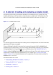
Circuit Board Modeler For ABAQUS Version 6.6-EF1 © 2007 ABAQUS, Inc. User’s Manual Table of Contents 1 Background .......................................................................................................................................4 Key PCB Modeler Features and Benefits ........................................................................................4 2. Summary ..........................................................................................................................................4 3. IDF File Import (Step 1)...................................................................................................................5 4. PCB Model Edit (Step 2) .................................................................................................................6 4.1 PCB Manager: Boards Tab ........................................................................................................6 4.1.1 Board Editor: Attributes Tab...............................................................................................6 4.1.2 Board Editor: Outline Tab...................................................................................................7 4.1.3 Board Editor: Cutout Tab ....................................................................................................7 4.1.4 Board Editor: Holes Tab .....................................................................................................7 4.1.5 Board Editor: Component Placement Tab .........................................................................7 4.1.6 Board Editor: Mesh Controls Tab ......................................................................................8 4.2 PCB Manager: Component Library Tab ...................................................................................8 4.2.1 Component Activation/Deactivation...................................................................................8 4.2.2 Material Assignment ...........................................................................................................8 4.2.2 Component Editor: ..............................................................................................................9 4.3 PCB Manager: Solder Ball Library Tab...................................................................................11 4.3.1 Solder Ball Selection .........................................................................................................12 4.3.2 Round Solder Ball .............................................................................................................12 4.3.3 SMD Solder Ball ...............................................................................................................14 4.3.4 MD Solder Ball .................................................................................................................15 4.3.5 Square Solder Ball.............................................................................................................16 5. Usability Issues ..............................................................................................................................17 5.1 Model Import and Mesh Generation ........................................................................................17 5.2 Solder Ball Array Generation...................................................................................................17 6. Installation of Plug-in.....................................................................................................................17 7. QA Test Problems ..........................................................................................................................17 8. References ......................................................................................................................................18 9. Appendix: PCB Modeler Dialogs ..................................................................................................19 9.1 PCB Manager Dialogs..............................................................................................................19 9.1.1 PCB Manager: Boards Tab ...............................................................................................19 9.1.2 PCB Manager: Component Library ..................................................................................20 9.1.3 PCB Manager: Solder Ball Library...................................................................................21 9.2 Board Editor Dialogs................................................................................................................22 9.2.1 Board Editor: Attributes Tab.............................................................................................22 9.2.2 Board Editor: Outline Tab.................................................................................................23 9.2.3 Board Editor: Cutouts Tab ................................................................................................24 9.2.4 Board Editor: Holes Tab ...................................................................................................25 9.2.5 Board Editor: Component Placement Tab ........................................................................26 9.2.6 Board Editor: Mesh Controls Tab .....................................................................................27 9.3 Component Editor Dialogs.......................................................................................................28 9.3.1 Component Editor: Attributes Tab ....................................................................................28 9.3.2 Component Editor: Geometry Tab ....................................................................................29 9.3.3 Component Editor: Mesh Controls Tab ............................................................................30 9.3.3 Component Editor: Solder Balls Tab ................................................................................31 9.4 Solder Ball Editor Dialogs .......................................................................................................32 9.4.1 Round Solder Ball Editor ..................................................................................................32 9.4.2 Square Solder Ball Editor..................................................................................................32 9.4.3 MD (Metal-Deposition) Solder Ball Editor ......................................................................33 9.4.4 SMD (Solder-Metal-Deposition) Solder Ball Editor ........................................................34 1 Background This documentation describes the use of the PCB Modeler plug-in for Abaqus/CAE developed and supported by Abaqus South Inc. The plug-in is used to generate printed circuit board models by importing information stored in the Intermediate Data Format (IDF). The printed circuit board information is stored in two files: a board file (.bdf) and component file (.ldf). The model resulting from the import of these data files will be geometry-based, fully meshed and ready for application of loads, boundary conditions and other attributes required for the analysis. Figure 1.1: Printed Circuit Board Photo Key PCB Modeler Features and Benefits Fully integrated with Abaqus/CAE 1. All model creation controls available from a single GUI 2. Selective merging of component and board geometries 3. Selective creation of tied constraints between components and board 4. Volume filters for import and activation of components 5. Automated mesh and region creation 1. Minimum diameter filter for import and activation of drilled holes Versatile mesh controls hierarchy 1. Instance-level overrides component-level which overrides board-level mesh controls 2. Controls include option to tie or merge component to board, component element size, mesh seed constraints, elements thru thickness, meshing algorithm, and component activation Solder ball array support 1. Four solder ball types in library 2. Automatic geometry, mesh, and section assignments of solder balls 3. Can define solder ball positions based on spacing or via a table 2. Summary The creation of a printed circuit board model using the PCB Modeler plug-in consists of a two-step process. The first step is the import of the component and board files generated from the various CAD packages and written in the IDF. The second step is to mesh the geometry that was imported. The IDF has been developed and supported by Intermedius Design1. This format has become the most widely used data format for the transfer of printed circuit assembly data between PCB layout and mechanical design systems. The first wide scale use of the IDF began in 1992 when version 2.0 was released. Subsequent versions 3.0 and 4.0 were released in 1996 and 1998, respectively, and have continued to be used as a de-facto nonproprietary standard format to the CAD industry. Most major CAD systems support import and export of printed circuit board information to the IDF. Component file (.ldf) The component file contains a description of the geometry of all of the components that may be used on the board. Components defined in this file are not necessarily placed onto the board. This file is simply a library file that defines the geometry of all components that may be placed onto the board. Board file (.bdf) The board file contains the attributes of the board including the outline, thickness, cutouts and drilled holes. Also included in this file are the placements of the components onto the board. Multiple instances of an individual component can be placed onto the board. Placement of the components involves translation and rotation of the component and whether it is to be positioned on the top or bottom of the board. The import step reads the component and board files and generates the appropriate geometry within Abaqus/CAE. During this first step, the Abaqus parts are generated based on the component definitions and the Abaqus instances are generated and positioned based on the placement information contained in the board file. The second step of the process involves setting the controls to specify mesh characteristics, board element size, component element size, minimum hole diameter to be included, and more. The options available through the plug-in implement already-existing underlying capabilities within Abaqus/CAE. The plug-in simplifies the use of theses capabilities by putting them all in one place and automatically applying them to hundreds or perhaps thousands of components at a time. These easy application, modification and removal of mesh controls is an essential aspect of this plug-in since multiple iterations of the model generation step are usually required to obtain a satisfactory model. Figure 2.1: Finite Element Model 3. IDF File Import (Step 1) The first step of importing the component and board files begins with the dialog shown in Figure 3 which is brought up from the menu item Plug-ins > PCB Modeler > Step 1: Import . The information from the import step will be stored on the mdb.customData object of the Abaqus/CAE model and is stored to be model specific. In other words, the PCB information is imported into the current model and will not be available once the current model has changed. Consequently, individual models may contain separate circuit board models. The first two entries of the import dialog allow the user to select the board and component files. The browse button automatically filters the files based on the .bdf and .ldf suffixes. The next option is the choice of the unit of length. The header of the board file specifies the unit of length for all of the information contained within the board file. This means that board definition, as well as, the component placement information, are defined using the same unit of length. For every component defined in the component file, the component geometry and the corresponding unit of length is specified. This unit of length may differ from component to component and from the board’s unit of length. Typically the units of length of the board and component files are consistent throughout, but the Pub Model plug-in requires the user to specify the unit of length so that all information translated from these files will be translated into a single consistent unit of length. The final option on the import dialog allows the user to filter out components based on volume. A board model typically contains hundreds, if not thousands, of components and component placement (component instance) definition. During this step, the plug-in generates an Abaqus part and an Abaqus part instance for every component definition and placement definition, respectively. If every component is imported, this can result in very large models which are very cumbersome, if not impossible, to work with. It is recommended that the volume filter be used to reduce the number of components, and thus the number of instances, imported into Abaqus/CAE. Once the import step is completed, the user can not go back and re-import specific components that were initially filtered out. A complete import would need to occur. However, after the first import step components may be deactivated in order to avoid including them in the generation of the model. So it is recommended to filter out those components that are certain not to be needed in the model and to proceed with the import of components that may or may not be required in the model since they can later be deactivated if necessary. Figure 3.1: IDF File Import Dialog 4. PCB Model Edit (Step 2) The second step of the process of creating a printed circuit board model is to bring up the PCB Manager dialog invoked from Plug-ins > PCB Modeler > Step 2: Edit. This dialog, shown in Appendix Figure 9.1-1, provides the user with options required in the building of the finite element model. Options include selection of mesh controls, element types, components to merge or tie to the board, solder ball array creation, and more. All information imported from the board and component files is made available for modification or correction from the PCB Manager dialog or other dialogs available from it. 4.1 PCB Manager: Boards Tab Selecting the Boards tab of the PCB Manager provides of the table of boards available in the model as shown in appendix 9.1.1. More than one board can be activated in a model. The boards can be edited, copied, renamed and deleted. The instance names of the individual boards must be unique to the board. Selecting the Edit button from the PCB Manager brings up the Board Editor dialog as shown in appendix 9.2.1. 4.1.1 Board Editor: Attributes Tab The board material, total board thickness, and solder mask layers are defined under the attributes tab as shown in appendix 9.2.1. The inclusion of solder mask layers on the top and/or the bottom of the board is optional. If a solder mask is included, the material and thickness must be chosen for each mask. The PCB Modeler will subtract the thickness of the masks from the total board thickness and will partition the board at the interface between the solder mask and board, then assign the appropriate material properties to both regions. The use of solder masks is generally combined with solder ball creation. However, the solder masks may be included by themselves on the board and the components as shown in Figure 4.1.1. When used with solder balls, the solder geometry will be cut out of the solder masks. 6 Figure 4.1.1: Board and Component with Solder Masks (Green) 4.1.2 Board Editor: Outline Tab The outline of the board is shown graphically under the Outline tab as shown in appendix 9.2.2. The outline is plotted in black and the cutouts in read. If any changes are made to outline or to the cutouts, the modified outline can be readily viewed before submission of the Circuit Board dialog by clicking the Plot Current Outline button. 4.1.3 Board Editor: Cutout Tab All of the cutouts that are imported from the board file are made available for editing in the form of a cutout table as shown in Appendix 9.2.3. They can be edited, deleted, renamed, activated, and deactivated. When a cutout is selected for editing, the Cutout dialog box is opened. A plot of the cutout outline provides a graphical representation to assist in recognizing problems. Any changes to the outline can be readily viewed before submission of the cutout dialog by selecting the Plot Current Outline button. Since cutouts can define a circular outline, they can be confused with holes when viewing the resulting geometry. A circular cutout and a drilled hole are imported and accessed differently in the plug-in, but once made part of the model provide the same circular cutout of the board. 4.1.4 Board Editor: Holes Tab Printed circuit boards typically contain thousands of holes. Some holes are used for mounting the board to the chassis, others for running wires or devices through, and others for soldering components to the board. The diameters of the holes range from those which can significantly affect the behavior of the model such as board mounting holes to those the size of pin holes which would have no affect on the model. If all of the holes were included, the model creation within Abaqus/CAE would be unacceptably slow since the resulting model would be immense. An option is provided to set the minimum diameter of the holes to be included as shown in Appendix 9.2.4. Boards are often constrained at mounting points using screws and washers. A column has been included in the holes table to specify the size of a partition to be created surrounding a hole. The partition simplifies the creation of regions to be used for boundary conditions or load applications. A value of 1.0 (default) for this entry will signify that no partition is to be created. 4.1.5 Board Editor: Component Placement Tab All of the component instances that are imported from the board file are made available for editing in the form of an instance table as shown in appendix 9.2.5. They can be edited, copied, deleted, renamed, activated, and deactivated. When a component instance is selected for editing, the Instance dialog box is opened. This allows all attributes of the instance to be modified. An offset from the board value is imported from the board file for each component instance. Currently, this value is ignored. When a component instance is deactivated, it does not get deleted during model generation. Abaqus/CAE simply activates or deactivates the part instance in question. Only when attributes of the component instance other than the activation flag are changed does the instance get deleted and recreated. 7 4.1.6 Board Editor: Mesh Controls Tab The mesh controls tab, as shown in Appendix 9.2.6, provides controls that will be applied to every component in the model. With the exception of element shape and element interpolation, all controls may be overridden for any given component as described in section on controls hierarchy. Allowing variations in element shape and element interpolation would require tie constraints between varying regions. Mesh controls are applied using a hierarchy from broad to specific: board-level to component-level to instance-level. The available controls are: Component constraint to board (tied or merged) Component element size Number of elements through thickness Mesh seed constraint (free, fixed, or increase only) Meshing algorithm: Advancing Front or Medial Axis Activation Instance-level controls override component-level controls which, in turn, override board-level controls. As a default, component and instance-level controls are all turned off upon import. An example of a useful application of this control scheme would be if the components are chosen to be merged with the board. However, assume the gap between a pair of components is orders of magnitude smaller than the components themselves. Since the meshing algorithm would be forced to fit at least a single element spanning the gap, the resulting mesh density in the area would be very high resulting in an overlylarge mesh. The alternative would be to set the component constraint for the instances in question to tie, thus avoiding the unnecessarily fine mesh between the components. Other examples of the mesh-controls scheme might include the requirement for fine meshes on particular instances which reside in critical locations, while other instances derived from the same component reside in less critical locations. 4.2 PCB Manager: Component Library Tab Since the creation of the mesh consumes most of the model creation time, a toggle is available to allow creation of the geometry of the model, but disallow the creation of the mesh. This provides an efficient method to run through a number of model generation iterations in order to determine adequate component and component instance activations. If modifications are made to the board or components a note is posted on the PCB Manager dialog that the database is out-of-date with the current model. Changes to components or the board are performed through separate dialogs which are described in more detail later. When these changes are submitted through the respective dialogs, the changes are immediately submitted to the data base. The model is not regenerated and made up-to-date until the PCB Manager dialog itself is submitted. 4.2.1 Component Activation/Deactivation The PCB Manager dialog shown in Appendix 9.1.2 contains a table of the components imported into Abaqus/CAE sorted by component volume. In Abaqus terminology, these are the parts that were created during the import step. Multiple part instances of these components can be placed onto the board. The table permits the deactivation and activation any component. The deactivation of a component results in the deactivation of all the resulting component instances within Abaqus/CAE. Deactivation of components or component instances does not result in the deletion of the component or instance. The performance of the deletion of parts and part instances within Abaqus/CAE is significantly degraded in models containing a large number of part instances, hence it is recommended to deactivate components as opposed to removing them. 4.2.2 Material Assignment Assignment of material properties to the components is most efficiently done from the PCB Manager dialog. Multiple components can be selected from the table and assigned a single material definition simultaneously. All components placed onto the board and the board itself must be assigned material properties before the 8 PCB Manager can be submitted and the model generated. Submission of the material assignment dialog from the PCB Manager occurs upon submission. In other words, the material assignments are applied immediately upon submission of the material dialog and not delayed until submission of the PCB Manager. Material orientations are assigned to each component and follow along with the component as it is translated and rotated onto the top or bottom of the board. The orientation assignments are made regardless of whether the component is tied or merged to the board. 4.2.2 Component Editor: Occasionally the component information imported may be invalid. For example, the component file may have mistakenly assigned an invalid thickness of zero to a component. The PCB Manager allows the component information to be modified by clicking on a component in the table and selecting the Edit button. The Component dialog, as shown in Appendix 9.3.1, is brought up allowing the modification of all the attributes of the component including the thickness. The Component dialog may also be brought up by selecting the Pick(Edit) button. This option simply allows the picking of the component from the assembly as opposed to the selection from the table. The model must be shown at the assembly-level for this option to be available. Since there are often upwards to a thousand component definitions, it is usually easier to pick components of interest rather than select them from the component table. 4.2.2.1 Component Editor: Geometry Tab A plot of the outline of the component is shown to help diagnose potential errors in the outline. Corrections to the outline may be made in the dialog and viewed before submission of the dialog by clicking the Plot Current Outline button. 4.2.2.2 Component Editor: Mesh Controls Tab The component-level controls are available by selecting the Mesh Controls tab of the Component Editor. The available options are shown in Appendix 9.3.3. Component-level mesh controls are also available from the Component dialog and are discussed in more detail in Section 4.1.6. 4.2.2.3 Component Editor: Solder Balls Tab A number of options related to solder balls are available through the Component Editor. An option is available to include a solder mask between the component and the board. A material and thickness is assigned to the solder mask. This option is available regardless of whether or not solder balls are included. If solder balls are included, then the solder ball geometry is cut out of the component solder mask. If the component geometry is selected to be merged with that of the board, then an option is available to either merge the solder mask geometry with the solder balls, or allow the interface between the two to remain independent. Merging the geometry implies that the mesh of the mask and solder ball share the same nodes at the interface shown in red in Figure 4.2.2.3-1. 9 Figure 4.2.2.3-1: Component Solder Mask Options The Component Editor provides for the specification of a solder ball array in two ways: rectangular grid and tabular. The grid approach requires a uniform spacing in the x and y direction, although the spacing may bar, and requires a single type of solder ball throughout. If more than one type of solder ball is required, or the spacing of the layout is not uniform, then the tabular approach is required. The filling of the table of solder ball locations can be facilitated in two ways. Firstly, if the cursor is placed in the first row and column of the blank table, then a right click of the mouse will enable the table to be filled by importing a text file of locations. The three columns of the text file must be separated by commas. Often this type of text file is easily made available from CAD tools. The second way to fill the table is to propagate the rectangular grid definition into the table by selecting the Fill > button. This button populates the table from the rectangular grid definition. Once the table is populated, individual entries can be modified accordingly. 10 Figure 4.2.2.3-2: Solder Ball Array by Pitch Figure 4.2.2.3-3: Solder Ball Array by Table Since the geometry creation of solder balls can be very time consuming, it’s important to define the layout of the solder balls properly the first time. To ensure the layout is correct, clicking the Plot Current Outline button from the Geometry tab will plot the outline of the component in black along with the outline of each solder ball in blue as shown in Figure 4.2.2.3-4. This plot is based on the current information in the dialog, not the information stored on the database. Figure 4.2.2.3-4: Component/Solder Ball Array Plot 4.3 PCB Manager: Solder Ball Library Tab 11 The Solder Ball tab provides the tools to create a library of solder balls. A variety of solder balls are available. Once created, they can be referenced from within the Component Dialog to specify the solder ball array. The solder balls stored in the library can be edited, copied, and deleted. When a solder ball is modified or deleted, the plug-in will scan through all of the components to see if the solder ball is used within the component. If it is used, the solder ball will be modified or removed from within the component. This will require the component to be regenerated, thus the operations of editing or deleting a solder ball can be time consuming for components with large arrays of solder balls. 4.3.1 Solder Ball Selection Selecting the Create button form the solder ball library tab will bring up a dialog requiring the choice of solder balls. Choosing a solder ball type and selecting Continue will bring up dialogs specific to each type of solder ball. Each dialog is shown in Appendix 9. Figure 4.3.1: Solder Ball Library Tab Each solder ball type has a different geometry. The Square solder ball consists of a simple geometry which is quickly generated. This type is intended for larger arrays of solder balls since the resulting solder ball may consist of a single element. The SMD and MD are more complex solder balls containing board and substrate pads. Because of the more complex geometries, finer meshes are required and thus they are not suitable for large arrays of solder balls. The Round solder ball is simple in that it does model board or substrate pads, thus it can be used for larger arrays of solder balls. Each type of solder ball can generate on boards and substrates with or without solder masks. The geometry of the solder ball will be modified if a solder mask exists. The sections below show illustrations of how each type of solder ball will be generated with and without solder masks. 4.3.2 Round Solder Ball The most commonly used type of solder ball is a simple round solder ball. It can be used in large arrays of coarsely meshed balls, or can be meshed more finely to accurately capture the shape of a solder ball. 12 The shape of the round solder ball will vary depending on whether the circuit board or the substrate contains a solder mask. Figure 4.3.2-1 shows the cross-section of a possible round solder ball mesh without any solder masks present. Figure 4.3.2-1: Round Solder Ball – No Masks The presence of a solder mask changes the shape of the solder ball resulting in thin slivers of elements on either the top or bottom of the solder balls. Because these thin slivers of elements can significantly increase the mesh density of the ball, it is not recommended to use solder masks when generating large arrays of solder balls. Figure 4.3.3-2 shows the cross-section of a possible round solder ball mesh with the solder masks colored in green. Figure 4.3.2-2: Round Solder Ball – With Masks The round solder ball contains only a horizontal partition dividing the ball into a top and bottom portion. No vertical partitions are made in the solder ball by default. This has the advantage that coarser meshes can be applied to the solder ball, but the disadvantage of less control over the mesh as shown in Figure 4.3.2-3. 13 Figure 4.3.2-3: Possible Geometry/Mesh of Round Solder Ball An option is available to partition the solder ball into four quadrants. This forces a more uniform shape of the solder ball elements. This can, however, increase the geometry and mesh creation times and increase the size of the mesh. The option to Include Quad Partitions is available on the Round Solder Ball Dialog as shown in Figure 4.3.2-4 and the resulting modified mesh is shown in Figure 4.3.2-5. Figure 4.3.2-4: Option to Partition Round Solder Ball Figure 4.3.2-5: Round Solder Ball Geometry/Mesh With Quad Partitions 4.3.3 SMD Solder Ball 14 The Solder-Metal-Deposition (SMD) solder ball is a more complex solder ball which models the pads between the solder ball and substrate and board. Because of this added complexity, this type of solder ball is generally not used in large arrays of solder balls. Figure 4.3.3-1 shows an SMD solder ball without solder masks. Figure 4.3.3-2 shows an SMD solder ball with solder masks. The solder masks are colored green and the pads are in blue. Figure 4.3.3-1: SMD Solder Ball Geometry Figure 4.3.3-2: SMD Geometry with Solder Masks 4.3.4 MD Solder Ball The Metal-Deposition (MD) solder ball is similar to the SMD solder ball in that it includes the board and substrate pads. The substrate pad is modeled in the same way as the SMD ball, but the board pad is modeled differently. Instead of the solder ball resting on the board pad as in the case of the SMD solder ball, the solder wraps around the board pad in the case of the MD solder ball. 15 Figure 4.3.4-1: MD Solder Ball Geometry Figure 4.3.4-2: MD Geometry with Solder Masks 4.3.5 Square Solder Ball The Square type of solder ball is a simple solder ball which does not model any of the pads. It’s intended for use in vary large arrays since it can consist of a single element. 16 Figure 4.3.5: Square Solder Ball Geometry 5. Usability Issues 5.1 Model Import and Mesh Generation Most difficulties which will arise when using the PCB Modeler plug-in stem from the sheer size of the models being generated. Even smaller models can easily reach upwards to a million degrees of freedom. The potentially large model sizes can cause the graphic interface of the plug-in, as well as Abaqus/CAE, to be slowed significantly. Creation of overly-large meshes may consume all of the memory on the machine resulting in aborts during mesh creation and the raising of an ipc_connection error. The following tips may help to improve success in using the plug-in: Use the minimum volume criteria during the import. The reduced number of part instances in Abaqus/CAE will dramatically improve the speed of the plug-in GUI, as well as, the speed of the model generation. Care must be taken not to try to merge components which are very close together. The resulting mesh could be so fine that Abaqus/CAE uses all of the memory on the machine and hangs up or aborts during mesh creation. Avoid trying to merge components to the board using hex elements if there is any overlap between the components. Any overlap will disallow creation of a hex mesh and require meshing with tetrahedral elements. 5.2 Solder Ball Array Generation When generating models with large arrays of solder balls, use the Round or Square solder balls and use the Advancing Front meshing option. Test problems 7.1 through 7.4 provide some examples of obtaining large arrays of solder balls. 6. Installation of Plug-in When you start ABAQUS/CAE, it searches for plug-in files in the following directories and all their subdirectories: abaqus_dir\cae\abaqus_plugins where abaqus_dir is the ABAQUS parent directory. home_dir\abaqus_plugins where home_dir is your home directory. current_dir\abaqus_plugins where current_dir is the current directory. ABAQUS/CAE will import any files in these directories that match the naming convention *_plugin.py. Thus, if It is preferred that any user in question who has access to the ABAQUS installation be allowed access to the plug-in, then a folder named pcb should be created under the abaqus_dir\cae\abaqus_plugins folder and the *.pyc files installed under that pcb folder. If the plug-in should be made available only on a user-by-user basis, then a folder named pcb should be created under a folder named home_dir\abaqus_plugins in the user’s home directory and the *.pyc files installed under that pcb folder. 7. QA Test Problems A number of QA problems have been included with the plug-in. The dialog is brought up through the menu item Plug-ins > PCB Modeler > Test Cases. Since these tests are fairly small but test all of the plug-in functionality, it is recommended that these be run and experimented with in order to familiarize oneself with the workings of the plug-in. Multiple tests may be selected to be run. The QA scripts runs the tests, compares to baseline results stored with the application, and brings up a dialog summarizing the comparison. An Abaqus/CAE model named “PcbTestModel” is created and saved of the last test chosen. Thus if a particular feature is of interest, the user can scan through the test descriptions and run the test that best uses the feature of interest. The resulting model “PcbTestModel” will be created and readily available for editing and testing 17 8. References IDF Specification by Dave Kehmeier, Intermedius Design Integration, www.intermedius.com. ABAQUS References (ABAQUS Version 6.6-EF1) Analysis User’s Manual ABAQUS Scripting User’s Manual ABAQUS GUI Toolkit User's Manual 18 9. Appendix: PCB Modeler Dialogs 9.1 PCB Manager Dialogs 9.1.1 PCB Manager: Boards Tab 19 9.1.2 PCB Manager: Component Library 20 9.1.3 PCB Manager: Solder Ball Library 21 9.2 Board Editor Dialogs 9.2.1 Board Editor: Attributes Tab 22 9.2.2 Board Editor: Outline Tab 23 9.2.3 Board Editor: Cutouts Tab 24 9.2.4 Board Editor: Holes Tab 25 9.2.5 Board Editor: Component Placement Tab 26 9.2.6 Board Editor: Mesh Controls Tab 27 9.3 Component Editor Dialogs 9.3.1 Component Editor: Attributes Tab 28 9.3.2 Component Editor: Geometry Tab 29 9.3.3 Component Editor: Mesh Controls Tab 30 9.3.3 Component Editor: Solder Balls Tab 31 9.4 Solder Ball Editor Dialogs 9.4.1 Round Solder Ball Editor 9.4.2 Square Solder Ball Editor 32 9.4.3 MD (Metal-Deposition) Solder Ball Editor x 33 9.4.4 SMD (Solder-Metal-Deposition) Solder Ball Editor 34