1
Board file (.bdf) The board file contains the attributes of the board including the outline, thickness, cutouts
and drilled holes. Also included in this file are the placements of the components onto the board. Multiple
instances of an individual component can be placed onto the board. Placement of the components involves
translation and rotation of the component and whether it is to be positioned on the top or bottom of the board.
The import step reads the component and board files and generates the appropriate geometry within
Abaqus/CAE. During this first step, the Abaqus parts are generated based on the component definitions and
the Abaqus instances are generated and positioned based on the placement information contained in the
board file.
The second step of the process involves setting the controls to specify mesh characteristics, board element
size, component element size, minimum hole diameter to be included, and more. The options available
through the plug-in implement already-existing underlying capabilities within Abaqus/CAE. The plug-in
simplifies the use of theses capabilities by putting them all in one place and automatically applying them to
hundreds or perhaps thousands of components at a time.
These easy application, modification and removal of mesh controls is an essential aspect of this plug-in since
multiple iterations of the model generation step are usually required to obtain a satisfactory model.
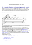
Figure 2.1: Finite Element Model
3. IDF File Import (Step 1)
The first step of importing the component and board files begins with the dialog shown in Figure 3 which is
brought up from the menu item Plug-ins > PCB Modeler > Step 1: Import . The information from the import step will
be stored on the mdb.customData object of the Abaqus/CAE model and is stored to be model specific. In
other words, the PCB information is imported into the current model and will not be available once the
current model has changed. Consequently, individual models may contain separate circuit board models.
The first two entries of the import dialog allow the user to select the board and component files. The browse
button automatically filters the files based on the .bdf and .ldf suffixes.
The next option is the choice of the unit of length. The header of the board file specifies the unit of length for
all of the information contained within the board file. This means that board definition, as well as, the
component placement information, are defined using the same unit of length. For every component defined
in the component file, the component geometry and the corresponding unit of length is specified. This unit of
length may differ from component to component and from the board’s unit of length. Typically the units of
length of the board and component files are consistent throughout, but the Pub Model plug-in requires the
user to specify the unit of length so that all information translated from these files will be translated into a
single consistent unit of length.