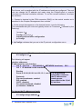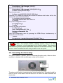
1
USER MANUAL
VERSION 4.21
interstage
Phistersvej 31, 2900 Hellerup, Danmark
Telefon 3946 0000, fax 3946 0040
www.interstage.dk
- pro audio with a smile
INDEX
Chapter I INTRODUCTION
5
1. About this Manual
5
Chapter II ABOUT KRONOS
6
1. INTRODUCTION
2. KRONOS PARTS
2.1. Kronos Base Device
2.2. Kronos Extension racks
Chapter III Kronos Installation
1. Before installing
2. Mounting in the rack
3. Installing the Kronos
3.1. Connecting the power
3.2. Connecting the controller card
3.3. Connecting the alarm relay:
3.4. Connecting the E1 or T1 lines:
3.5. Connecting the audio modules:
4. Installing Extension Subracks
4.1. Hot swapping of the extension modules:
5. Starting up the Kronos
Chapter IV Control Card
1. Functional description
2. About E1/T1 Multiplexing
2.1. Channels
2.2. Routes
3. Configuring the master clock for the multiplexer
4. IP traffic through E1/T1 channels
5. Indicators on the Control Module
Chapter V E1/T1 Module
1. Functional description
2. Configuration
2.1. E1 Interface:
2.2. T1 Interface
3. Monitoring
3.1. LEDS
6
7
7
9
10
10
10
10
10
12
15
16
16
16
17
18
19
19
20
20
20
21
21
22
23
23
23
23
24
24
24
Chapter VI Audio Encoder Card
26
1. Functional description
2. Configuration
2.1. Coding algorithms
2.2. Selecting the audio source
2.3. Gain adjustment
2.4. Activating the test tone
3. Monitoring
3.1. LEDs
26
26
26
30
30
30
30
30
Chapter VII Audio Decoder Card
1. Functional description
2. Configuration
2.1. Decoding algorithms
2.2. Selecting the audio output
2.3. Gain adjustment:
2
KRONOS User’s Manual V4.21
31
31
31
31
34
34
2.4. Activating the test tone:
3. Monitoring
3.1. LEDs
35
35
35
Chapter IV Synchronous data card
36
1. Functional Description
2. Configuration
2.1. Installing the physical drivers
2.2. Speed selection
2.3. Control signals (Handshaking)
3. Monitoring
3.1. LEDs
Chapter VII Power Supply
1.1. Block Diagram of the power supply modules:
Chapter VIII Expansion Module
Appendix A Technical specifications
1. E1/T1 Module
1.1. E1 - Tx:
1.2. E1 - Rx:
1.3. T1 - Tx :
1.4. T1 – Rx:
2. Audio Encoder Module
2.1. Stereo audio input:
2.2. Audio properties:
2.3. Compression:
2.4. BANDWIDTH MPEG LAYER II
2.5. BANDWIDTH MPEG LAYER III
3. AUDIO DECODER MODULE
3.1. Stereo audio output:
3.2. Audio properties:
3.3. Compression:
3.4. Delays
4. Synchronous data module
4.1. Speed
4.2. Data format
4.3. Interface
4.4. Supported signals in the interface V35
4.5. Connector
5. Power
5.1. AC Power Supply:
5.2. DC Power Supply:
6. Environmental
7. Physical
7.1. Size
Appendix B Connectors
1. E1/T1 Module
2. Control Module
2.1. Console connector
2.2. GPO Connector
3. Audio Encoder Module
3.1. Audio XLR Connector:
3.2. Audio DB9 Connector:
3.3. Auxiliary data connector:
4. Audio Encoder Module with two audio connectors
4.1. AES/EBU:
4.2. Analog Audio:
3
KRONOS User’s Manual V4.21
36
36
36
37
37
38
38
39
39
41
42
42
42
42
42
43
44
44
44
44
45
45
46
46
46
46
47
48
48
48
48
48
48
49
49
49
49
49
49
50
50
51
51
51
52
52
52
52
53
53
53
5. Audio Decoder Module
5.1. Audio XLR connector:
5.2. Audio DB9 Connector:
5.3. Auxiliary data connector:
6. Decoder module with two connectors
6.1. AES/EBU:
6.2. Analog Audio:
7. Data Module
7.1. Data Connector
7.2. Cable description (SCSI-DB25)
4
KRONOS User’s Manual V4.21
54
54
54
54
55
55
55
56
56
56
Chapter I
INTRODUCTION
1. About this Manual
This manual provides information about the more important features of the
Kronos multiplexer. It also includes a customer installation guide and a reference
guide to explain how the unit works and assist in its configuration. Users configuring
the unit themselves should use either this manual or the ProdysControl
configuration manual depending on whether configuration is by console port
(RS232) or LAN interface. ProdysControl is an optional SNMP based management
application.
The sections in this manual are as follows:
About Kronos: description of the more important features.
Kronos parts: description of the component parts of the Kronos.
Kronos installation guide.
Control module.
E1/T1 module.
Audio Encoder Module.
Audio Decoder Module.
Appendix A: Technical specifications.
Appendix B: Connectors.
5
KRONOS User’s Manual V4.21
Chapter II
ABOUT KRONOS
1. INTRODUCTION
KRONOS E1/T1 Multiplexer is a system that allows transportation of voice
channels, high quality audio and data across 2.048 Mbps or 1544 Mbps structured
links (E1 or T1 circuits), using time division multiplexing (TDM). The Kronos
multiplexer supports up to four E1 or T1 links (two links for each installed E1/T1
interface card). It is possible to drop/insert time slots across any of the connected
E1 circuits.
It is implemented using a modular construction on a common backplane
architecture in 19” rack. It is possible to cascade up to 8 racks together. This all
gives great flexibility in the choice of input and output modules depending on the
requirements of each application.
The more important features of the unit are as follows:
▪
▪
▪
▪
▪
▪
▪
▪
▪
▪
6
Ability to connect up to four E1/T1 circuits to one base device.
Drop/insert across any of the connected E1/T1 circuits.
AC or DC (48V) power supply.
Option of redundant AC or DC power supply.
Hot swapping of modules to make servicing and updating easier.
Option to extend the configuration with additional racks (up to a maximum of
8 racks).
Local or remote control and configuration through RS232 (Telnet) or LAN
interface (SNMP).
Ability to assign time-slots for IP traffic dynamically. Routed interconnection
of LAN through E1 circuits.
Totally configurable audio modules by software: selection of analog or digital
interface as well as encoding/decoding algorithm.
Bi-directional module of synchronous data (two ports per module). The
interface can be configured V35/X21 and as DTE or DCE.
KRONOS User’s Manual V4.21
2. KRONOS PARTS
The Kronos multiplexer is made up of a base device and additional racks
where the number of modules is more than can be fitted in one rack. Below is a
description of the individual parts and the position where they have to be fitted
inside the rack.
2.1. Kronos Base Device
2.1.1 Components
•
Kronos frame:
19”-4U Rack mount. The place where the modules are is divided in 18
slots (1 slot = 4 TE = 20.32 mm).
The back panel of the rack has identified connectors in the following way:
CN1: for the installation of the main power supply.
CN2: for the installation of the secondary power supply.
SLOTS 0-15: for the installation of the different modules.
The using of these slots is subject to the following
restrictions.
CN1
7
CN2
•
Main power supply:
It is always installed in the connector CN1 of the back panel. The main
power supply can be AC or DC. It takes up 10 TE (50.8 mm.).
•
Secondary power supply:
It is always installed in the connector CN2 of the back panel. This power
supply is optional and it is used as redundant in the case of failure of the
main power supply. It can be AC o DC. It takes up 10 TE (50.8mm.) of
the frame this is fitted next to the main power supply.
•
CONTROL module:
This module looks after the configuration and monitoring of the system.
It includes a GPO connector. It must be installed in the slot 13 or 14 of
the main rack. It takes up one slot ( 4TE = 20.32 mm) of the frame.
KRONOS User’s Manual V4.21
•
E1/T1 module:
E1 or T1 interface module depending on the installed daughter card. Each
line is identified as Line 1 and Line 2 and it has two BNC connectors, one
for transmission (Tx) and one for reception (Rx) and a RJ45 connector.
The Kronos allows two modules (up to four E1 or T1 links) they must be
installed in the slots 0 and 1 of the rack. Each module takes one slot.
•
Audio ENCODER module:
There is only one model of encoder card as all its parameters are
configurable by software: analog or digital input and coding algorithm.
This module can be installed in any of the slots 2-13 of the rack. It can
also be installed in the slot 14 when this is not be occupied by the control
module. Each module takes two slots when the connectors are XLR or
only one slot if the module is supplied with sub D 9 connectors.
•
Audio DECODER module:
There is only one model of encoder card as all its parameters are
configurable by software: analog or digital output and decoding algorithm.
This module can be installed in any of the slots 2-13 of the rack. It can
also be installed in the slot 14 when the control module does not occupy
this. Each module takes two slots when the connectors are XLR or only
one slot if the module is supplied with sub D 9 connectors.
•
SYNCHRONOUS DATA module:
The interface is X21/V35 and can work as DCE or DTE. Each module has
two data ports. This module can be installed in any of the slots 2-13 of
the rack. It can also be installed in the slot 14 when it is not occupied by
the control module or in the slot 15 if the expansion module is not fitted.
Each module takes up one slot.
•
EXTENSION module:
This module is needed to connect more than one frame. This module
must be installed in the slot 15 of the main rack and in slots 0 and 15 of
the secondary racks. This module takes up one slot.
Below is a summary of the restrictions on the position of the modules that
can be installed in the Kronos rack:
Main Rack
MODULE
Main power supply (AC o DC)
Secondary power supply (AC o DC)
E1/T1 module
Audio Encoder Module
Audio Decoder Module
Data Module
Control Module
Expansion Module
8
KRONOS User’s Manual V4.21
Position in the rack
Connector CN1
Connector CN2
Slots 0 – 1
Slots 2-12 & 14
Slots 2-12 & 14
Slots 2-12 & 15
Slots 13 – 14
Slot 15
Table I: Configuration of the Kronos Main rack
Secondary Racks
MODULE
Position in the rack
Main power supply (AC o DC)
Connector CN1
Secondary power supply (AC o DC)
Connector CN2
Audio Encoder Module
Slots 1..14
Audio Decoder Module
Slots 1..14
Data Module
Slots 1..14
Expansion Module
Slot 0 & 15 depending
on the configuration.
Table II: Configuration of the Kronos secondary rack
2.2. Kronos Extension racks
There is an option to extend the number of audio or data modules by
connecting additional racks using the expansion module. Each of these racks
has its own independent power supply, and the ability to also install a
redundant power supply.
In the case of further expansion racks, it will be necessary to install
expansion modules in order to allow racks to be connected in cascade. The
expansion modules are fitted in the slots 15 and 0 of the backplane. It is
possible to install audio as well as data modules in the rest of the slots of the
backplane (1-14).
E1/T1 or control modules cannot be installed in the expansion racks.
9
KRONOS User’s Manual V4.21
Chapter III
Kronos Installation
1. Before installing
The Kronos unit is usually supplied ready configured to the customer’s
specification. It is recommended that you check that the shipped
configuration is as requested.
2. Mounting in the rack
The Kronos requires 4U rack (4U = 44.45 x 4 mm). We recommend when
installing the Kronos, to leave a free space in its upper and lower part to
guarantee a correct ventilation of the unit.
3. Installing the Kronos
All the connections of the Kronos, with the exception of the power, are
accessible from the front of the unit. None of the cards, with the exception
of the power supplies, requires the configuration of jumpers or switches.
3.1. Connecting the power
The Kronos rack allows installation of an AC or DC main and/or redundant
power supply. The rack is supplied with the customer specified configuration
of power supplies. It is important that the end user checks which power
supply/supplies are fitted before using the unit.
The power connections for both the AC and DC power supplies are fitted to
the back panel of the Kronos rack. There is only one power input connector
for each type of power supply i.e. The AC IEC connector feeds both AC power
supplies and the DC connector feeds both DC supplies.
10
KRONOS User’s Manual V4.21
DC POWER
SUPPLY
EARTH
SCREW
AC POWER
SUPPLY
3.1.1 Connecting the 48 VDC power supply
The 48VDC connector is located in the rear panel of the Kronos. The unit is
supplied with this connector to ease the installation. The connection procedure is as
follows:
1.- Only use UL 12 AWG standardized cable. We recommend to peel the
cable approximately 8 mm ( 3 inches).
2.- Ensure that the external power supply or battery is disconnected.
3.- Connect the GND screw to the installation ground.
4.- Connect the negative terminal of the external power supply to the
connection point of the DC INPUT connector.
-
5.- Connect the positive terminal of the external power supply to the
installation ground and to the +connection point of the DC INPUT connector.
11
KRONOS User’s Manual V4.21
ATTENTION:
Extra precautions must be taken when connecting the DC
power supply. A wrong installation could damage the unit.
Make sure that there no voltage in the DC power supply cable
before you connect it.
3.2. Connecting the controller card
The control card has two connectors (CON & LAN) in order to allow management of
the Kronos. Depending on which one is used, the access to the configuration and
management functions of the Kronos are different.
3.2.2 Management for console: CON connector
The CON connector provides a serial port connection. It acts as DCE. The terminal
that is connected to that port, must be configured as below:
Protocol: UART
Line speed: 9600 bps
Parity: None
Data Bits: 8
Stop Bits: 1
Flow control: None
Terminal Emulation: VT-100
CONTROL MODULE
RJ45
RJ45-DB9 Adapter
RJ45
DB9M
9600 bps.
8 bits.
No parity
1STOP bit
DB9H
Serial port
12
KRONOS User’s Manual V4.21
3.2.3 Remote management: LAN connector
The Controller card has a TCP/IP stack, which allows the remote management
through:
•
•
TELNET service: Emulates the serial port console
SNMP service: Allows centralized management of the unit with software, typically
ProdysControl or HP Openview.
Remote management can be carried out using the Ethernet Interface (LAN
connector) through E1/T1 channels, at least one time slot needs to be configured to
support IP traffic.
Management of local Kronos units (those connected to our LAN through the Kronos
LAN connector) as well as of remote Kronos units can be carried out, since the
Kronos routes the IP traffic through the E1/T1 links.
Prodys can supply an application for the management of the Kronos (ProdysControl)
it allows access to the control and monitoring functions of the Kronos unit.
If you connect a network card (Workstation) to the LAN interface of the Kronos, you
must use a cross-over LAN cable.
13
KRONOS User’s Manual V4.21
IP protocol Configuration:
The Kronos unit is supplied with the IP address and mask pre-configured. The end
user can change the IP address and mask using the ProdysControl or console
connector and terminal emulation software. To use the console software, the steps
are as follow:
1.- Connect a terminal to the CON connector (RJ45) on the control module as is
described in the Chapter “Management from console”.
2.- At the prompt that appears on the terminal screen, type the following:
(The commands that you enter are typically shown as “command ↵” followed by the
Enter key)
*process 4 ↵
Config> protocol ip ↵
Internet protocol user configuration
Ip Config>
3.- Ip Config> indicates that you are in the IP protocol configuration menu.
To check the current IP address and mask:
IP Config>list all ↵
The following will appear:
Interface addresses
IP addresses for each interface:
intf 0 192.1.2.3
255.255.255.0 NETWORK broadcast,
intf 1 IP disabled on this interface
fill 0
Routing
Route to 0.0.0.0,0.0.0.0 via 192.1.2.1, cost 0 The programmed
information related to
Protocols
the IP address and
Directed broadcasts: enabled
mask appears
RIP: enabled
associated to the 0 (intf
OSPF: disabled
0) interface.
Per-packet-multipath: disabled
Ip classless: disabled
To change the IP address and mask:
IP Config>change address ↵
14
KRONOS User’s Manual V4.21
The following screen will appear:
New address to be changed [0.0.0.0]?
Type the new IP address:
New address to be changed [0.0.0.0]192.1.2.4 ↵
Address mask [255.255.0.0]?
Type the new mask:
Address mask [255.255.0.0] 255.255.0.0 ↵
Following, it is needed to program the internal IP address which value will be the
same as the one previously entered:
IP Config>set internal-ip-address
Internal IP address [192.1.2.4]? 192.1.2.4
IP Config>
To quit the configuration menu:
IP Config>exit ↵
Config>
To save the new configuration:
Config>save ↵
Save configuration [n]? Yes ↵
Saving configuration...Ok
Config>
Leave the configuration menu by pressing the CTRL-P keys simultaneously to
restart the control module:
*restart
Are you sure to restart the system?(Yes/No)? Yes ↵
Since 1.5.0 Control Module software version, there is a DB15
connector in the frontal panel of the Control module. This connector
offers a seven general purpose optoisolated outputs to be activated remotely. There
is also a switch to disable the alarm relay located on the rear panel.
New
3.3. Connecting the alarm relay:
If an alarm condition is present, Kronos will activate the alarm relay. When an alarm
condition is detected, the normally open contact will be closed.
ALARM
RELAY
The alarm cut-off switch is located on the Control module front. This switch could be
used to silence a local alarm once the source of the alarm has been identified and
deactivated.
15
KRONOS User’s Manual V4.21
3.4. Connecting the E1 or T1 lines:
The Kronos allows up to four E1 or T1 circuits to be connected. Each E1 module
has two interfaces, installing a daughter card on the baseboard for each interface
enables these. There is the option of using either BNC or RJ45 connectors for each
interface.
3.5. Connecting the audio modules:
The audio modules are configurable by software, even the type of input or output.
Each module supports analog as well as digital interface. A LED on the front of the
module indicates the interface that is active. Which connector is in use depends on
the mode selected.
3.5.4 Audio Encoder Module:
Analog inputs: AN/DIG led is lit indicating that the analog interface is
active. The connections are the same as the panel markings. i.e. L and R.
Digital input: AN/DIG led is off indicating that the digital interface is
active. The AES/EBU audio input is connected to the connector marked
AES/EBU INPUT.
3.5.5 Audio Decoder Module:
Analog outputs: Led AN/DIG is lit indicating that the analog interface is
active. The connections are the same as the panel markings. i.e. L and R.
Digital output: AN/DIG led is off indicating that the digital interface is
active. The AES/EBU audio output connected to the connector marked
AES/EBU OUTPUT. Optionally to lock to an external sync source use the
connector with marked AES/EBU SYNC.
4. Installing Extension Subracks
There is the possibility to increase the number of audio or data modules by
connecting in cascade additional racks using the extension modules. Each rack has
an independent power supply with the possibility to install a secondary one as well.
It will be necessary to install in the extension racks, extension modules to
allow the connection in cascade. The extension modules will always be inserted in
slots 15 and 0 in the back panel. It will be possible to install as many audio
modules as data modules in the remaining slots free (1..14) in the back panel.
The connection between subracks will be made by using a standard 50 ways
SCSI cable.
This cable is supplied together with the units, if requested according to the
configuration inquired by the user.
The way to interconnect the subracks will be as follows:
16
KRONOS User’s Manual V4.21
ATTENTION:
The last connected subrack needs an additional extension board
(without connection cable) for buses finishing.
The extension boards have some jumpers which configuration depends on
the subrack they are installed in and the slots they occupy. Please see this
configuration as follows:
Jumpers configuration of the Extension board
Subrack
Slot
Jumper
Jumper
P1
P2
0 (Main Subrack)
15
OPEN
OPEN
1,3,5,7
1,3,5,7 (If it is the last subrack)
1,3,5,7 (If it is not the last subrack)
2,4,6,8
2,4,6,8
15
0
0
0
15
CLOSED
OPEN
OPEN
CLOSED
OPEN
CLOSED
OPEN
OPEN
OPEN
OPEN
Jumper P3
OPEN
OPEN
CLOSED
OPEN
OPEN
OPEN
4.1. Hot swapping of the extension modules:
ATTENTION:
The removal of one of the extension boards will interrupt the
operation of the whole system if the interconnection cable has
not been unplugged.
When an extension board needs to be first unplug, firstly
unplugged the cable to allow operation of the modules
connected to the lower subracks.
17
KRONOS User’s Manual V4.21
5. Starting up the Kronos
The startup sequence takes about 30 seconds. During the startup sequence, the
control module starts up and detects the configuration of the Kronos, loading the
saved configuration or the default configuration if it finds a newly installed module.
18
KRONOS User’s Manual V4.21
Chapter IV
Control Card
1. Functional description
The main function of the Controller Card is to allow the management of the
KRONOS. Management can be carried out LOCALLY as well as REMOTELY. For
local management, the Controller Card has a Serial Port and for remote
management, it has an ETHERNET LAN interface. The Controller card also provides
with the following features:
•
Control of the KRONOS clock.
The Controller Card monitors the state of the E1/T1 Line clocks and
generates the Master clock for the KRONOS. If the line clock fails, the next
active clock is assigned as Master clock.
•
Auto configuration of hot-plugged modules.
When a card is inserted in to the Frame, the controller Card detects it
automatically and configures the switching routes. In that way this card does
not interfere with the current status of the unit. If the configuration is valid,
it will start working immediately.
•
Auto configuration of the interchanged cards.
If a faulty module is replaced, the Controller card detects the new one
and the configuration is restored, the new card works to the same
configuration as the faulty one.
•
Management of remote units.
In situations where there are two or more installed KRONOS units
network (IP) connectivity through E1/T1 can be configured. The controller
card adds the ability to use E1/T1 time slots for transportation of IP data in
order to allow configuration of remote units. You can manage the remote
units using Telnet or SNMP.
19
KRONOS User’s Manual V4.21
2. About E1/T1 Multiplexing
Kronos multiplexes/demultiplexes structured E1/T1 circuit data (G.703 /
G.704). Two concepts need to be understood in order to carry out configuration:
Channel and Route.
These two elements are all that are necessary to fully define a multiplexed
configuration.
2.1. Channels
A channel is a data flow (bits) at a speed of N x 64 kbps, where N is less than
32. The user must define the channel before setting the route.
•
E1/T1 channels:
An E1/T1 channel is a “multiple 64 kbps" in one direction only, that is, N time-slots
of one received or transmitted E1/T1 line. A channel transports a sequential flow of
bits through an E1/T1 line at a speed of N x 64 kbps.
The channels are defined by the user and must specify the following:
•
Which E1/T1 line is to be used as well as the direction of the
communication input (Rx) or output (Tx).
•
Which time-slots make up the channel? The order in which they are
specified does not matter, as the bits are always taken in the order they
received or transmitted through the E1/T1 circuit.
2.2. Routes
A route is the connection from input module to channel (groupings of E1 or T1 time
slots) to output module (Audio or Data) or visa versa. According to the kind of the
channel defined, the mode of operation is called multiplexed, demultiplexed or
drop/insert.
Type of source channel
E1/T1
Input module
E1/T1
Type of destination
channel
Output module
E1/T1
E1/T1
Mode Operation
Demultiplexed
Multiplexed
Drop/insert
It is necessary to define the channels at each end of the E1/T1 circuit. Both
channels of a route must have the same bandwidth (effective speed), and time slot
allocation. You cannot define more than one route with the same destination.
However, You can define more than one route with the same origin and different
destination channels, in other words distribution.
20
KRONOS User’s Manual V4.21
3. Configuring the master clock for the multiplexer
The KRONOS multiplexer uses one clock source at a time, the currently active clock
source is called the MASTER clock. The source of the clock is configurable, there
are up to eight possible sources that can be used as MASTER clock for the
Multiplexer, they are as follows:
A clock for each E1/T1 link that is recovered from the line i.e. up to 4
external clocks (normal operation is to ‘lock’ to the clock supplied by the
Telco).
An internal clock for each E1/T1 link that is from a crystal on the E1/T1
module i.e. up to 4 internal clocks.
The different sources are:
Clock ID
1
I1
2
I2
3
I3
4
I4
Source
Clock from Line 1 of module in slot 0
Internal clock from Line 1 of module in
Clock from Line 2 of module in slot 0
Internal clock from Line 2 of module in
Clock from Line 1 of module in slot 1
Internal clock from Line 1 of module in
Clock from Line 2 of module in slot 1
Internal clock from Line 2 of module in
slot 0
slot 0
slot 1
slot 1
In order to set the MASTER clock that the KRONOS will use, you must assign
priorities for each of the available clock sources. The priority is based on a list of
clocks where the top element is the highest priority and the bottom one, the lowest
prior. In order to assign a priority within the ProdysControl application, each clock
can be moved in relation to each other.
4. IP traffic through E1/T1 channels
The controller card is able to communicate by IP with remote units through
E1/T1 channels. It is possible to access the whole network of KRONOS units for
centralized management and configuration from an only one management
application, as the controller is also a router this allows the interconnection of
networks using those links.
In order to get IP access through E1/T1 channels, there is an internal line in
the control module. This is a line of 1280 Kbps (20 timeslots) that is multiplexed to
the four E1/T1 lines of the KRONOS. On this internal line there are PPP interfaces,
one for each IP channel (bi-directional) that we want to establish. Kronos units are
supplied with the pre-configured PPP connections. The user only has to assign time
slots for the IP traffic in each one of the available E1/T1 lines. Note the maximum
number of time slots is 20 (summing the time slots of all the lines).
21
KRONOS User’s Manual V4.21
5. Indicators on the Control Module
The control module has three LEDs on its front panel.
S
LAN
M
22
Status of the Control Card:
Green: Ok
Red: Not Ok.
Status of the Ethernet
connection:
Green: Connected to LAN.
Red: No connection.
Not used.
KRONOS User’s Manual V4.21
Chapter V
E1/T1 Module
1. Functional description
Each E1/T1 card is able to manage up to two structured E1/T1 bi-directional
links, following the G.703/G.704 recommendations. The card has the following
functions:
• Data reception/transmission through E1/T1 circuits.
• Provide the master clock to the multiplexer.
• E1/T1 drop/insert.
2. Configuration
The E1/T1 module detects the installed interface daughter board (E1 or T1)
and provides access to the correct configuration parameters for each.
2.1. E1 Interface:
The following parameters can be configured:
Option
CRC4
Line
Impedance
Value by
default
Enable
75 ohm.
Description
Automatic generation of bits VRC-4. The received bits VRC4 will also be monitored and the LED of the front panel will
be updated.
It is possible to select:
• 75 ohm unbalanced ( BNC connector).
• 120 ohm balanced ( RJ11 connector)
ATTENTION:
The line impedance selection requires also the configuration of
the P1 jumper located on the E1 modules.
(120)
P1
(75)
23
KRONOS User’s Manual V4.21
2.2. T1 Interface
For the T1 interface it is necessary to configure the length of the attached cable.
The available options are as follows:
•
•
•
•
•
0-133 ft (41m.)
133-266 ft. (81m.)
266-399 ft. (122 m.)
399-533 ft. (162 m.)
533-655 ft. (183 m.)
3. Monitoring
The E1/T1 module provides status information as below:
LINE STATUS DESCRIPTION
DOWN
Line data not detected
DATA DETECT Line data has been detected but the frame synchronization has
not been detected
UP
Line data has been detected and frame has been synchronized
RESYNC
The frame synchronization has been lost. System is trying to
synchronize again
NOT_PRESENT G703 Daughter board has not been detected correctly.
3.1. LEDS
The E1/T1 card has three leds to indicate its status.
LINE 1 Line 1 status
LINE 2 Line 2 status
S
Clock configuration
3.1.1 Line status
LINE 1 or LINE 2
RED (solid)
RED (blinking)
GREEN (blinking)
YELLOW (blinking)
24
KRONOS User’s Manual V4.21
STATUS
G703 daughter card Not detected
Line DOWN
Line UP
Line in loop
3.1.2 Clock configuration
S
RED (solid)
GREEN (blinking)
YELLOW (blinking)
RED-YELLOW
25
KRONOS User’s Manual V4.21
CLOCK
Wrong MASTER clock
L1 and L2 RED (solid).
Card generating MASTER clock
Card receiving clock.
Connecting internal PLL
L1 and L2 YELLOW (solid).
Chapter VI
Audio Encoder Card
1. Functional description
The audio encoder module allows the transmission of audio signals through the
E1/T1 circuits in different compression formats. All the parameters are configurable
by software even the selection of the analog or digital interface (AES/EBU). A single
encoder module can access the four E1/T1 line interfaces using independent
channels simultaneously, i.e. the time slots used on each line can be different.
2. Configuration
The configuration options for the audio encoder module depend on the compression
algorithm that is selected. The two audio channels of each encoder can be used as
two independent encoders each using a different algorithm, or encoding each audio
input using the same algorithm but using a different bit rate for each input.
2.1. Coding algorithms
2.1.1 G711:
It allows the transmission of audio signals using the standard of telephone
transmission (bandwidth 3.4 KHz). Using G711, each audio input takes up a
single time slot of an E1/T1 link (64 Kbps). Each audio input in G711 mode
can be either A-Law or µ-Law.
2.1.2 G722:
Allows the transmission of high quality voice signal (7 KHz). Using G722,
each audio input takes up a single time slot of an E1/T1 link (64 Kbps).
Synchronization can be selected between statistical framed (SRT) or H221.
2.1.3 MPEG:
Depending on the selected configuration, the bandwidth as well as the delay
will change. Both parameters are explained in the technical specification
section. The encoder module allows the following MPEG encoding formats:
LAYER: II or III
FREQUENCY: 16, 24, 32 or 48 KHz.
BITRATE: 64, 128, 192, 256, 320 or 384 Kbps.
MODE: Stereo, Joint Stereo, Dual or Mono.
26
KRONOS User’s Manual V4.21
The allowed sampling frequency, bit rate and mode combinations will depend
on the imposed restrictions by the MPEG standard. They are as follows:
MPEG LAYER II Fs = 24/16 KHz
MPEG LAYER II Fs = 48/32 KHz
B
R
A
T
E
64
128
192
256
320
384
Stereo
X
X
X
X
X
X
MODE
Joint Stereo
X
X
X
X
X
X
Dual
X
X
X
X
X
X
Mono
X
X
X
B
R
A
T
E
64
128
192
256
320
384
B
R
A
T
E
64
128
192
256
320
384
MODE
Joint Stereo
X
X
X
X
X
Dual
X
X
X
X
X
Mono
X
X
X
X
X
MODE
Joint Stereo
X
X
Dual
X
X
Mono
X
X
MPEG LAYER III Fs = 24/16 KHz
MPEG LAYER III Fs = 48/32 KHz
Stereo
X
X
X
X
X
Stereo
X
X
B
R
A
T
E
64
128
192
256
320
384
Stereo
X
X
MODE
Joint Stereo
X
X
Dual
X
X
Mono
X
X
It is also possible to enable auxiliary data with the following options:
NO DATA, 300, 1200, 2400, 4800, 9600 or 19200 bps.
Each module has a DB9 connector to transmit auxiliary data.
There is only one auxiliary data channel available per module. However,
when working in 2 codecs mode, the auxiliary data can independently be
enabled in each codec.
2.1.4 J41:
The J.41 standard is recommended for encoding 15KHz mono analog signals
for digital transmission at 384Kbit/s. You can use 2 mono digital codecs for
stereo. The J.41 standard encoding laws are based on a uniformly quantized
14-bit per sample PCM technique with companding and employ elevensegment 14- to 11-bit instantaneous A-law companding. There is also a
parity bit for error detection. It is calculated from the 5 most significant bits
of the sample. For each 2 input samples we get an output code.
There are 2 variants of the standard:
Variant, A which is used in units that are based on a hierarchy
at 2048Kbit/s (E1).
Variant B, which is used in digital units that are based on a
digital hierarchy at 1544Kbit/s (T1).
27
KRONOS User’s Manual V4.21
There is an option for setting emphasis on the audio signals according to
recommendation J.17. Also the recommendation G.735 for channel (time slot)
allocation can be set.
Special compensation mode delays for compatibility with other
multiplexers (only for J.41):
In order to be compatible with other manufacturers multiplexers a special
mode can be selected that introduces a delay between the two channels. This
ensures that the audio channels are phase coherent when connecting a
Kronos unit to other manufacturers multiplexers. The delay offset between L
and R channels of a module depends on the assignment of time slots that are
selected for each audio channel. This assignment must be made according to
the G.735 standard.
A
B
C
D
E
1,2,3 – 17,18,19 slots.
4,5,6 – 20,21,22 slots.
7,8,9 – 23,24,25 slots.
10,11,12 – 26,27,28 slots.
13,14,15 – 29,30,31 slots.
Depending the selected group for the L channel, the assignment of time slots
for the R channel, should be chosen from the table below:
A
B
C
D
E
A
X
-
B
11.72µS
X
-
C
23.44µS
11.72µS
X
-
D
35.16µS
23.44µS
11.72µS
X
-
E
46.88µS
35.16µS
23.44µS
11.72µS
X
The time slots that have been assigned to the L channel are in the left
column and the slots to be assigned to the R channel are along the top. The
values indicate the compensated delay for each combination.
2.1.5 J42:
The J.42 standard is recommended for encoding 7KHz mono analog signals
for digital transmission 192Kbit/s. The J.42 standard encoding laws are based
on a uniformly quantized 14-bit per sample PCM technique with companding
and employ eleven-segment 14- to 11-bit instantaneous A-law companding.
There is also a parity bit for error detection. It is calculated from the 7 most
significant bits of the sample. For each 2 input samples we get an output
code.
There are 2 variants of the standard:
28
KRONOS User’s Manual V4.21
Variant, A which is used in units that are based on a hierarchy
at 2048Kbit/s (E1).
Variant B, which is used in digital units that are based on a
digital hierarchy at 1544Kbit/s (T1).
There is an option for setting emphasis on the audio signals according
to recommendation J.17. In the case of the stereo, only one digital channel at
384Kbit/s is used, joining the signals of both channels according to J.41
standard.
2.1.6 J57:
The ITU-T J.57 recommendation is used for the transmission of digital sound
signals with studio quality by digital hierarchy H11 or H12. The J.57 (H12)
standard encoder receives 20bit samples of stereo digital audio at 48KHz. It
encodes blocks of 96 audio samples (48 per channel). Giving a 1ms
companding block, near instantaneous companding from 20 to 15 bits/sample
is applied with 8 coding ranges. Each coded sample has a parity bit (96 parity
bits per 1ms companding block) some of these bits are used in order to
transmit the scale factor information for each channel, the status of the
channel, additional data and MultiFrame Alignment signals (every 1536bits or
192 blocks = 192ms), MFA, and frame slip detection, FSD (in each block of 1
ms). In the case of H12, 3 audio bits and 1 user bit per sample are sent. The
H12 level provides a total of 20 bits per sample, and H11 provides a total of
16 bits per sample. To simplify interworking between H11 and H12 channels,
the companding of the audio signal is such that the samples are compressed
for transmission in the H11 channel. In the H12 channel, extra bits may be
conveyed, to improve resolution of the audio coding and provide a user data
channel. H11 uses 24 time slots and H12 30 at 64 Kbps.
New
29
Since 1.4.0 Encoder Module software version, it is possible to transmit
ancillary data when J57 is selected.
KRONOS User’s Manual V4.21
2.2. Selecting the audio source
The audio source can be selected between analog or digital.
2.3. Gain adjustment
The gain of each channel can be adjusted between +6 and –6 dB in steps of
1dB.
2.4. Activating the test tone
We can active or deactivate a test tone of 1004 Hz and –12 dBFs in each
channel.
This tone will replace the input audio to all intents and purposes (vumeters,
coding...), but will not be affected by the volume control.
3. Monitoring
3.1. LEDs
There are three LED’s in the front of each module:
AN/DIG
L
R
30
If it is ON, it indicates that the
analog input is selected.
If it is OFF, it indicates AES/EBU
input is selected.
Level indicator:
OFF: < -78 dBFs (no audio input).
GREEN: -78 dBFs..-9 dBFs.
ORANGE: -9 dBFs..-3.5 dBFs.
RED: > -3.5 dBFs (Overload).
Level indicator:
OFF: < -78 dBFs (no audio input).
GREEN: -78 dBFs..-9 dBFs.
ORANGE: -9 dBFs..-3.5 dBFs.
RED: > -3.5 dBFs (Overload).
KRONOS User’s Manual V4.21
Chapter VII
Audio Decoder Card
1. Functional description
The audio decoder module allows the reception of audio signals through E1/T1
circuits using different compression formats. All the parameters are configurable by
software, even the selection of the analog or digital interface.
2. Configuration
The configuration options of the audio decoder module depend on the selected
compression algorithm. For each algorithm, there is an option of working as a dual
decoder or as two independent decoders. This second option allows the decoding of
each received channel using the same algorithm but using different bit rates for
each channel.
2.1. Decoding algorithms
2.1.1 G711:
It allows the reception of audio signals using the standard telephone
transmission (3.4 KHz bandwidth). Using G711, each audio channel takes up
one time slot of an E1/T1 link (64 Kbps). Each channel in G711 mode can be
decoded according to A-Law or µ-Law.
2.1.2 G722:
Allows the reception of a high quality voice signal (7 KHz). Using G722, each
audio channel takes up one time slot of an E1/T1 link (64 Kbps).
Synchronization can be selected between statistical framed (SRT) or H221.
2.1.3 MPEG:
Depending on the selected configuration this will change the bandwidth and
the delay. Both parameters are explained in the technical specification
section. The decoder module allows the following MPEG decoding formats:
•
•
•
•
31
LAYER: II or III
FREQUENCY: 16, 24, 32 or 48 KHz.
BITRATE: 64, 128, 192, 256, 320 or 384 Kbps.
MODE: Stereo, Intensity Stereo, Joint, Dual or Mono.
KRONOS User’s Manual V4.21
The allowed sampling frequency, bit rate and mode combinations will depend
on the imposed restrictions by the MPEG standard. They are as follows:
MPEG LAYER II Fs = 24/16 KHz
MPEG LAYER II Fs = 48/32 KHz
B
R
A
T
E
64
128
192
256
320
384
Stereo
X
X
X
X
X
X
MODE
Joint Stereo
X
X
X
X
X
X
Dual
X
X
X
X
X
X
Mono
X
X
X
B
R
A
T
E
64
128
192
256
320
384
B
R
A
T
E
64
128
192
256
320
384
MODE
Joint Stereo
X
X
X
X
X
Dual
X
X
X
X
X
Mono
X
X
X
X
X
MODE
Joint Stereo
X
X
Dual
X
X
Mono
X
X
MPEG LAYER III Fs = 24/16 KHz
MPEG LAYER III Fs = 48/32 KHz
Stereo
X
X
X
X
X
Stereo
X
X
B
R
A
T
E
64
128
192
256
320
384
Stereo
X
X
MODE
Joint Stereo
X
X
Dual
X
X
Mono
X
X
It is also possible to enable auxiliary data with the following options:
NO DATA, 300, 1200, 2400, 4800, 9600 or 19200 bps.
Each module has a DB9 connector to transmit auxiliary data.
There is only one auxiliary data channel available per module. However,
when working in 2 codecs mode, the auxiliary data can independently be
enabled in each codec.
2.1.4 J41:
The J.41 standard is recommended for decoding 15KHz mono analog signals
for digital transmission at 384Kbit/s. You can use 2 mono digital codecs for
stereo. The J.41 standard encoding laws are based on a uniformly quantized
14-bit per sample PCM technique with companding and employ elevensegment 14- to 11-bit instantaneous A-law companding. There is also a
parity bit for error detection. It is calculated from the 5 most significant bits
of the sample. For each 2 input samples we get an output code.
There are 2 variants of the standard:
Variant, A which is used in units that are based on a hierarchy
at 2048Kbit/s (E1).
32
KRONOS User’s Manual V4.21
Variant B, which is used in digital units that are based on a
digital hierarchy at 1544Kbit/s (T1).
There is an option for setting emphasis on the audio signals according to
recommendation J.17. Also the recommendation G.735 for channel (time slot)
allocation can be set.
Special compensation mode delays for compatibility with other
multiplexers (only for J.41):
In order to be compatible with other manufacturers multiplexers a special
mode can be selected that introduces a delay between the two channels. This
ensures that the audio channels are phase coherent when connecting a
Kronos unit to other manufacturers multiplexers. The delay offset between L
and R channels of a module depends on the assignment of time slots that are
selected for each audio channel. This assignment must be made according to
the G.735 standard.
A
B
C
D
E
1,2,3 – 17,18,19 slots.
4,5,6 – 20,21,22 slots.
7,8,9 – 23,24,25 slots.
10,11,12 – 26,27,28 slots.
13,14,15 – 29,30,31 slots.
Depending the selected group for the L channel, the assignment of time slots
for the R channel, should be chosen from the table below:
A
B
C
D
E
A
X
-
B
11.72µS
X
-
C
23.44µS
11.72µS
X
-
D
35.16µS
23.44µS
11.72µS
X
-
E
46.88µS
35.16µS
23.44µS
11.72µS
X
The time slots that have been assigned to the L channel are in the left
column and the slots to be assigned to the R channel are along the top. The
values indicate the compensated delay for each combination.
2.1.5 J42:
The J.42 standard is recommended for encoding 7KHz mono analog signals
for digital transmission 192Kbit/s. The J.42 standard encoding laws are based
on a uniformly quantized 14-bit per sample PCM technique with companding
and employ eleven-segment 14- to 11-bit instantaneous A-law companding.
There is also a parity bit for error detection. It is calculated from the 7 most
significant bits of the sample. For each 2 input samples we get an output
code.
33
KRONOS User’s Manual V4.21
There are 2 variants of the standard:
Variant, A which is used in units that are based on a hierarchy
at 2048Kbit/s (E1).
Variant B, which is used in digital units that are based on a
digital hierarchy at 1544Kbit/s (T1).
There is an option for setting emphasis on the audio signals according
to recommendation J.17. In the case of the stereo, only one digital channel at
384Kbit/s is used, joining the signals of both channels according to J.41
standard.
2.1.6 J57:
The ITU-T J.57 recommendation is used for the transmission of digital sound
signals with studio quality by digital hierarchy H11 or H12. The J.57 (H12)
standard encoder receives 20bit samples of stereo digital audio at 48KHz. It
encodes blocks of 96 audio samples (48 per channel). Giving a 1ms
companding block, near instantaneous companding from 20 to 15 bits/sample
is applied with 8 coding ranges. Each coded sample has a parity bit (96 parity
bits per 1ms companding block) some of these bits are used in order to
transmit the scale factor information for each channel, the status of the
channel, additional data and MultiFrame Alignment signals (every 1536bits or
192 blocks = 192ms), MFA, and frame slip detection, FSD (in each block of 1
ms). In the case of H12, 3 audio bits and 1 user bit per sample are sent. The
H12 level provides a total of 20 bits per sample, and H11 provides a total of
16 bits per sample. To simplify interworking between H11 and H12 channels,
the companding of the audio signal is such that the samples are compressed
for transmission in the H11 channel. In the H12 channel, extra bits may be
conveyed, to improve resolution of the audio coding and provide a user data
channel. H11 uses 24 time slots and H12 30 at 64 Kbps.
New
Since 1.4.0 Decoder Module software version, it is possible to receive
ancillary data when J57 is selected.
2.2. Selecting the audio output
The audio output can be selected between analog or digital.
2.3. Gain adjustment:
The gain of each channel can be adjusted between +6 –6 dB in steps of 1dB.
34
KRONOS User’s Manual V4.21
2.4. Activating the test tone:
The test tone of 1004 Hz and –12 dBFs can be activated or deactivated in
each channel without being affected by the gain control. If the decoder is
framed, its level will be reflected in the vumeters replacing the decoded
audio.
3. Monitoring
3.1. LEDs
There are three LED’s in the front of each module:
AN/DIG
L/SYNC
ON: shows the selected analog output.
OFF: shows the selected AES/EBU
output.
Framed audio LED:
OFF: Decoder not framed.
ON: Decoder framed.
The colour of the LED will vary depending
on the output audio level:
Green: less than –9 dBFs .
Orange: from -9dBFs to –3.5 dBFs
Red: more than –3.5 dBFs, overhead.
R/SYNC
Framed audio LED:
OFF: Decoder not framed.
ON: Decoder framed.
The colour of the LED will vary depending
on the output audio level:
Green: less than –9 dBFs .
Orange: from -9dBFs to –3.5 dBFs
Red: more than –3.5 dBFs, overhead
35
KRONOS User’s Manual V4.21
Chapter IV
Synchronous data card
1. Functional Description
The Data Card is able to manage up to two independent bi-directional lines of
synchronous data, each one at a speed selectable between 64 kbps and 1984 kbps.
The way these data lines are multiplexed across the E1/T1 time slots is totally
configurable, allowing great flexibility in the assignment of available resources.
The features of each one of these data lines are as follows:
•
•
•
•
•
V-35/X21 Interface with high-density connectors SCSI-20 (Micro-D).
Working as DCE or DTE.
Bi-directional data line, with the same Tx and Rx speed.
Transparent synchronous data line.
Selectable speed of n x 64 kbps, from 64 kbps up to 1984 kbps, with option
of deactivating the hand shaking lines (TD, CTS, DSR or DCD).
• Reception from any E1/T1 channel.
• Transmission/distribution to any E1/T1 channel.
The sum of speeds of the two data lines must not exceed 2048
kbps; otherwise only one of them will work.
2. Configuration
2.1. Installing the physical drivers
The drivers are on daughter boards that are fitted on the module main board. These
have the required interface circuitry to translate X21/V35 voltage levels to the
internal TTL levels. The position of the card determines whether the data module
works as DTE (data terminal equipment) or as DCE (data circuit equipment). Each
data connector has a driver card and you must follow the following steps in order to
install them:
1. Using normal anti-static precautions, the data module must not powered.
36
KRONOS User’s Manual V4.21
2. Position the driver card to match the annotation on the data module:
For DTE with the letter T (“Terminal”) nearest to the connector or as DCE with the
letter M (“Modem”) nearest the connector.
3. Install the driver card nearest to the connector which you intend to use.
If a connector is not going to be used, it is not necessary that it has the driver card
installed.
The orientation of the driver card determines if the data channel
works as DTE or as DCE.
2.2. Speed selection
The speed of each data channel can be configured between 64 kbps and 1984 kbps
(31x64 kbps), in intervals of 64 kbps. The default configured speed is 0.
2.3. Control signals (Handshaking)
The V35 interface incorporates control signals that are used by the communications
protocol. These signals can be used to detect the status of the line by monitoring
the relevant signals. In the case of DCE operation, the DTR and/or RTS signals will
be able to be used in order to determine the status of the line. When the Data
module detects the line drop, it ignores the received data and transmits binary zero
data through the E1/T1 time slots. Transmission from the module to the data line is
not affected.
There is an option of disabling the monitoring of these signals
(HANDSHAKING NONE). If this is set, and the Data module is not
connected random data will be transmitted through the
corresponding E1/T1 time slots.
The default configuration is that the status of the line is only detected by the DTR
signal (or DSR if the card works as DTE).
If you specify speed 0, CTS, DSR and DCD (RTS and DTR if it is DTE) will be
deactivated.
37
KRONOS User’s Manual V4.21
3. Monitoring
3.1. LEDs
Under normal working, the data card has three leds to indicate its status
LED S Card status
LED L1 Line 1 status
LED L2 Line 2 status
• Card state
Once the module is operational, the LED S will show steady green.
• Line state
The LED L1 reflects the line state of the LINE 1 connector, and the LED L2, the state
of the LINE 2 connector. The following table presents the possible line states
according to the color.
LED color
OFF
RED
YELLOW
GREEN
38
Line state
Not active. Speed 0 has been configured.
Not active. The reason could be the line
has dropped; the sum of the configured
time slots is over the allowed maximum, or
a temporary state.
Active. Some of the control signals are not
active: DSR, DCD and CTS in DTE mode,
and DTR and RTS in DCE mode.
Active.
KRONOS User’s Manual V4.21
Chapter VII
Power Supply
The Kronos accepts the installation of a AC or DC (48VDC) power supply. In
addition, it is possible to install in each subrack a second secondary power supply to
come into operation in case of failure of the main power supply.
For each type of power supply, there is a different power supply module and either
of them can work as main or secondary power supply.
The main power supply must always be installed in the CN1 connector of the
subrack and the secondary power supply in the CN2 connector.
The power supply requires the installation of a jumper
when working as main PS.
Please, before installing a power supply, always verify that
the jumper is correctly configured depending on the use of
the PS (main or secondary).
Jumper P1
Main power supply:
UP
P1
NOM
DWN
Secondary power supply:
UP
P1
NOM
DWN
1.1. Block Diagram of the power supply modules:
Both types of power supply (AC or DC) work the same way with the exception of
their input circuit which changes due to that each one of them admit a different
type of supply (AC or DC).
The power supplies give two types of supply to the Kronos:
+52 VDC / +48 VDC. When the power supply works as main PS, it supplies +52
volts. When working as secondary PS, the voltage is +48 volts. The P jumper is
installed to configure the operation mode so that the power supply will work as
main PS.
39
KRONOS User’s Manual V4.21
+5 VDC. This voltage is obtained and independent from the 48 volts of the
backpanel (or 52 volts when working as main power supply) generated in the
module itself.
Moreover, it is possible to monitor both voltages remotely from the control module
having each supply module the necessary devices to carry out this monitoring.
As shown in the following diagram, the control module gives information on the
voltage supplied by the power supply module as well as on the voltage available in
the backpanel.
There are two LEDs in the front panel of each power supply showing the state of
the voltages generated by the module itself.
AC/DC or
DC/DC
Converter
220VA
or
48VDC
P1
Out
On
+52
Off
+48
DC/DC
+48V BKp
+5V BKp
+5V Int
+48V Int
LED +5
LED +48
40
KRONOS User’s Manual V4.21
µ
C
Control
Bus
B
A
C
K
P
A
N
E
L
Chapter VIII
Expansion Module
When the number of audio or data modules needs to be extended, it will be
necessary to install extension modules to allow connection of additional racks in
cascade.
The extension modules occupy fixed positions within each subrack. An extesnion
module will be inserted in slot 15 of the main subrack and in slots 0 and 15 of the
following subracks.The connection between subracks will be carried out with a
standard 50 ways SCSI cable. This cable is supplied together with the units, if
requested according to the configuration inquired by the user.
The extension boards have programming bridges which configuration will depend on
the subrack it will be installed and the slot to be inserted in. Following is a table
with this configuration:
41
Jumpers configuration of the Extension board
Subrack
Slot
Jumper
Jumper
P1
P2
0 (Main Subrack)
15
OPEN
OPEN
Jumper
P3
OPEN
1,3,5,7
1,3,5,7 (If it is the last subrack)
1,3,5,7 (If it is not the last subrack)
2,4,6,8
2,4,6,8
OPEN
CLOSED
OPEN
OPEN
OPEN
KRONOS User’s Manual V4.21
15
0
0
0
15
CLOSED
OPEN
OPEN
CLOSED
OPEN
CLOSED
OPEN
OPEN
OPEN
OPEN
Appendix A
Technical specifications
1. E1/T1 Module
1.1. E1 - Tx:
•
•
•
•
•
•
Interface: According to G.703 recommendation
Line speed: ± 50 ppm (internal clock).
Connectors: BNC Coax. 75Ω / RJ45 120Ω 22AWG (0.6 mm).
Line code: HDB3 (High Density Bipolar of order 3 code).
Protection: Isolated output for transformer.
Jitter: ETS 300 011 and TBR12.
1.2. E1 - Rx:
•
•
•
•
•
•
Interface: According to G.703 recommendation.
Line speed: 2048 Kbps.
Connectors: BNC Coax. 75Ω / RJ45 twisted pair120Ω 22AWG (0.6 mm).
Line code: HDB3.
Protection: Isolated input for transformer
Tolerance to Jitter: according to ITU G.823.
1.3. T1 - Tx :
•
•
•
•
•
•
•
•
42
Interface: According to G.703 recommendation.
Line speed: 1544 Kbps ± 50 ppm (internal clock).
Adaptation to the shape of wave: DSX-1 (short haul) 0 at 655 ft / DS-1
(long haul) 0 dB at –22.5 dB.
Connector: RJ45 twisted pair 100Ω.
Line codes: B8ZS (bipolar with replacement of eight zeros) and AMI.
Framed: D4/ESF.
Protection: Isolated output for transformer.
Jitter: TR 62411.
KRONOS User’s Manual V4.21
1.4. T1 – Rx:
•
•
•
•
•
•
•
43
Interface: According to G.703 recommendation.
Line speed: 1544 Kbps.
Connectors: RJ45 twisted pair 100Ω.
Line codes: B8ZS/AMI.
Framed: D4/ESF.
Protection: Isolated input for transformer.
Tolerance to Jitter: according to TR 62411.
KRONOS User’s Manual V4.21
2. Audio Encoder Module
2.1. Stereo audio input:
Balanced analog input:
Maximum input level +22 dBu.
Input impedance 20KΩ.
Balanced digital input:
AES/EBU format: EIAJ CP-340 type I/IEC-958 Pro
Sampling rate converter: 1:3 to 3:1.
2.2. Audio properties:
Quantization: 24 bits A/D converter.
S/N ratio > 95 dB typical.
Crosstalk > 80 dB
Phase difference < 0.3º
2.3. Compression:
G711:
G722:
µ-Law and A-Law.
Two channels per module.
Two channels per module.
MPEG Layer II / III:
One stereo channel and up to two mono channels
per module.
Bit rates: 64, 128, 192, 256, 320 or 384 Kbps.
Fs = 48, 32, 24 or 16 KHz.
Modes = Mono, Dual, Joint Stereo or Stereo.
J41:
2 channels per encoder module.
15 KHz bandwidth.
Option to activate or de-activate pre-emphasis
according to standard J17.
J42:
2 channels per encoder module.
bandwidth.
Option to activate or de-activate pre-emphasis
according to standard J17.
44
KRONOS User’s Manual V4.21
J57:
1 stereo channel per encoder module.
24 KHz (@ 48KHz Fs) bandwidth.
H11 or H12.
2.4. BANDWIDTH MPEG LAYER II
Fs
16 KHz
24 KHz
32 KHz
48 KHz
Bit Rate
BANDWITH (KHz)
MONO
JOINT
DUAL/STEREO
STEREO
64 Kbps
128 Kbps
64 Kbps
128 Kbps
64 Kbps
128 Kbps
192 Kbps
256 Kbps
320 Kbps
384 Kbps
64 Kbps
7.5
7.5
11.25
11.25
11.5
15.0
15.0
10.5
7.5
7.5
11.25
11.25
6.0
13.5
15.0
15.0
15.0
15.0
5.25
7.25
7.5
7.125
11.25
5.0
11.5
15.0
15.0
15.0
15.0
4.5
128 Kbps
20.0
15.75
10.5
192 Kbps
20.0
20.0
13.5
256 Kbps
-
20.0
20.0
320 Kbps
-
20.0
20.0
384 Kbps
-
20.0
20.0
2.5. BANDWIDTH MPEG LAYER III
Fs
16 KHz
24 KHz
32 KHz
48 KHz
45
Bit Rate
64 Kbps
128 Kbps
64 Kbps
128 Kbps
64 Kbps
128 Kbps
192 Kbps
256 Kbps
320 Kbps
64 Kbps
128 Kbps
192 Kbps
256 Kbps
320 Kbps
KRONOS User’s Manual V4.21
BANDWITH (KHz)
MONO
DUAL/JOINT
STEREO/STEREO
7.5
7.5
10.0
11.3
15.0
15.0
15.0
15.0
15.0
15.0
18.0
20.0
20.0
20.0
7.5
7.5
8.0
11.3
8.0
15.0
15.0
15.0
15.0
8.0
18.0
20.0
20.0
20.0
3. AUDIO DECODER MODULE
3.1. Stereo audio output:
Balanced analog output:
Maximum output level +22 dBu.
Output impedance 50Ω.
Balanced digital output:
AES/EBU format: EIAJ CP-340 type I/IEC-958 Pro
Sampling rate converter: 1:3 to 3:1.
3.2. Audio properties:
Quantization: 24 bits D/A converter.
S/N ratio > 95 dB typical.
Crosstalk > 80 dB
Phase difference < 0.3º
3.3. Compression:
G711:
µ-Law and A-Law.
Two channels per module.
G722:
Two channels per module.
MPEG Layer II / III:
One stereo channel per module or up to two mono
channels per module.
Bit rates: 64, 128, 192, 256, 320 or 384 Kbps.
Fs = 48, 32, 24 or 16 KHz.
Modes = Mono, Dual, Joint Stereo or Stereo.
J41:
2 channels per decoder module.
15 KHz bandwidth.
Option to activate or de-activate De-emphasis
according to standard J17.
J42:
2 channels per decoder module.
7.5 KHz bandwidth.
Option to activate or de-activate De-emphasis
according to standard J17.
J57:
1 stereo channel per decoder module.
24 KHz (@ 48KHz Fs) bandwidth.
H11 or H12.
46
KRONOS User’s Manual V4.21
3.4. Delays
ENCODING MODE
G711
G722
J41
J42 (MONO)
J42 (STEREO)
J57-H11
J57-H12
MPEG LAYER II
Fs
8 KHz
16 KHz
32 KHz
16 Khz
16 KHz
48 KHz
48 KHz
16 KHz
24 KHz
32 KHz
48 KHz
16 KHz
24 KHz
MPEG LAYER III
BIT RATE
64 Kbps
64 Kbps
384 Kbps
192 Kbps
384 Kbps
1536 Kbps
1920 Kbps
All
All
All
All
64 Kbps
128 Kbps
64 Kbps
128 Kbps
64 Kbps
32 KHz
128 Kbps
192 Kbps
256 Kbps
320 Kbps
64 Kbps
48 KHz
128
192
256
320
Kbps
Kbps
Kbps
Kbps
Delay (ms)
8
7.6
3
6
6
6
6
280
196
154
110
334
300
258
208
Mono:344
Stereo,Dual:380
270
270
234
234
Mono:280
Stereo,Dual:308
212
186
164
166
These values are the total delay encode to decode.
47
KRONOS User’s Manual V4.21
4. Synchronous data module
4.1. Speed
From 0 to 1984 Kbps on E1 channels in steps of 64 Kbps.
From 0 to 1536 Kbps on T1 channels in steps of 64 Kbps.
4.2. Data format
Transparent data without restriction.
4.3. Interface
V35 or X21. Configurable as DCE or DTE according to installation of the driver
card.
4.4. Supported signals in the interface V35
DTR, RTS, DSR, DCD.
4.5. Connector
High-density connectors SCSI-20 (Micro-D) for each data port.
48
KRONOS User’s Manual V4.21
5. Power
5.1. AC Power Supply:
Nominal input: 230 Vac
Input range: 180-260 Vac
Fuse: 3A
Output power: 200 Watt max
5.2. DC Power Supply:
Nominal input: 48 VDC
Input range: -36..-72 VDC
Fuse: 8A
Output power: 200 Watt max
6. Environmental
Operating Temperature: 0 to +50 ºC
Humidity: 10 to 90% non-condensing.
7. Physical
7.1. Size
Rack: Height:4U ; Width:19inches ; Depth:370 mm.
AC Power supply: 5 TE = 50.8 mm
DC Power Supply: 5 TE = 50.8 mm.
E1/T1 Module: 4 TE = 20.32 mm.
Control Module: 4 TE = 20.32 mm.
Audio Encoder Module: 8 TE = 40.64 mm.
Audio Decoder Module: 8 TE = 40.64 mm.
Data Module: 4 TE = 20.32mm.
Expansion Module: 4 TE = 20.32 mm.
49
KRONOS User’s Manual V4.21
Appendix B
Connectors
1. E1/T1 Module
BNC
Rx
1
Rx+
2
Rx-
3
NC
4
Tx+
5
Tx-
6
NC
7
NC
8
NC
RJ45
BNC
Tx
E1/T1 CONNECTOR
50
KRONOS User’s Manual V4.21
2. Control Module
2.1. Console connector
1
NC
2
3
4
5
6
7
8
RXD
GND
NC
NC
GND
TXD
NC
2.2. GPO Connector
PIN
1
2
3
4
5
6
7
Maximum collector current = 50 mA.
51
KRONOS User’s Manual V4.21
SIGNAL
Output 1
Output 2
Output 3
Output 4
Output 5
Output 6
Output 7
PIN
9
10
11
12
13
14
15
SIGNAL
GND1
GND2
GND3
GND4
GND5
GND6
GND7
3. Audio Encoder Module
3.1. Audio XLR Connector:
PIN
1
2
3
SIGNAL
GND
+
-
3.2. Audio DB9 Connector:
PIN
1
6
2,3,4
5
9
SIGNAL
R+ (analog input) / AES-EBU input +
R - (analog input) / AES-EBU input GND
L+ (analog input)
L – (analog input)
3.3. Auxiliary data connector:
PIN
1
2
3
4
5
52
SIGNAL
NC
Tx
NC
NC
GND
KRONOS User’s Manual V4.21
PIN
6
7
8
9
SIGNAL
NC
NC
NC
NC
4. Audio Encoder Module with two audio connectors
4.1. AES/EBU:
PIN
1
6
2,3,4
5,9
SIGNAL
AES-EBU input +
AES-EBU input GND
NC
4.2. Analog Audio:
PIN
1
6
2,3,4
5
9
SIGNAL
R+ (analog input)
R - (analog input)
GND
L+ (analog input)
L – (analog input)
ENCODER
LED: Green
Red
Analog
Digital
AN
L
R
DIG
ANCILLARY
DATA
A
E
S
/
E
B
U
INPUT
A
N
A
L
O
G
53
KRONOS User’s Manual V4.21
Audio input selector
switch
5. Audio Decoder Module
5.1. Audio XLR connector:
PIN
1
2
3
SIGNAL
GND
+
-
5.2. Audio DB9 Connector:
PIN
1
6
2,3,4
5
9
SIGNAL
R+ (analog output) / AES-EBU Sync input +
R - (analog output) / AES-EBU Sync input GND
L+ (analog output) / AES-EBU output +
L - (analog output) / AES-EBU output -
5.3. Auxiliary data connector:
PIN
1
2
3
4
5
54
SIGNAL
NC
NC
Rx
NC
GND
KRONOS User’s Manual V4.21
PIN
6
7
8
9
SIGNAL
NC
NC
NC
NC
6. Decoder module with two connectors
6.1. AES/EBU:
PIN
1
6
2,3,4
5
9
SIGNAL
AES-EBU Sync input +
AES-EBU Sync input GND
AES-EBU output +
AES-EBU output -
6.2. Analog Audio:
PIN
1
6
2,3,4
5
9
SIGNAL
R+ (analog output)
R - (analog output)
GND
L+ (analog output
L - (analog output)
DECODER
AN
L
R
DIG
ANCILLARY
DATA
A
E
S
/
E
B
U
OUTPUT
A
N
A
L
O
G
55
KRONOS User’s Manual V4.21
7. Data Module
7.1. Data Connector
SIGNAL
Harting SCSI 20M
CONNECTOR
V.35 SIGNAL
1
2
3
4
5
6
7
8
11
12
13
14
15
16
17
18
20
S
Y
T
V
AA
X
H
U
P
R
C
D
E
B
F
W
A
TD+
TC- (Tx CLOCK -)
RD+
RC- (Rx CLOCK -)
TC+ (Tx CLOCK +)
RC+ (Rx CLOCK +)
DTR
ETCTDRDRTS
CTS
DSR
GND
CD
ETC+
GROUND
7.2. Cable description (SCSI-DB25)
56
SIGNAL
Harting SCSI 20M
CONNECTOR
V.35 SIGNAL
DB25
CONNECTOR
TD+
TCRD+
RCTC+
RC+
DTR
ETCTDRDRTS
CTS
DSR
GND
CDETC+
GROUND
1
2
3
4
5
6
7
8
11
12
13
14
15
16
17
18
20
S
Y
T
V
AA
X
H
U
P
R
C
D
E
B
F
W
A
14
15
16
17
18
19
20
24
2
3
4
5
6
7
8
9
1
KRONOS User’s Manual V4.21
interstage
Phistersvej 31, 2900 Hellerup, Danmark
Telefon 3946 0000, fax 3946 0040
www.interstage.dk
- pro audio with a smile