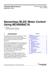
1
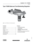
ENCODER/HALL-EFFECT
MOTOR
CAN
J6
J1
J4
SWITCHES
&
LEDs
3-PH MOSFET
BRIDGE
USB/SCI
BRIDGE
J9
J10
INPUTS
J2, J3
CAN
PH. LAYER
MOSFET DRIVERS
J7, J8
DAUGHTER BOARD
BDM for
USB Controller
USB
Electrical Characteristics
Legend:
POWER
SUPPLIES
SIGNAL CONDITIONING
DC BUS, PHASE voltages and currents,
BEMF
+5V, +3.3V, +3.3VA
Module
Connector
Figure 2-1 Block Diagram
2.2 Electrical Characteristics
The electrical characteristics in Table 2-1 apply to operations at 25 °C with a 24 V DC power supply
voltage. Maximal value of the input voltage can be higher than 24 V. A 50 V maximal input voltage value
is allowed, but the DC-bus and BEMF sensing circuits need to be modified. The divider resistors in these
circuits need to be changed to change sensing range up to 50 V, if required. It prevents scaled quantities
exceeding the maximum-allowed input voltage value on the controller input pins.
WARNING
If an input voltage higher than 24 V is applied, the controller daughter
board can be damaged.
3-Phase BLDC/PMSM Low-Voltage Motor Control Drive, Rev. 0
18
Freescale Semiconductor