1
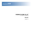
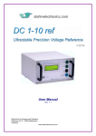
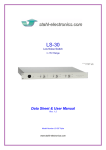
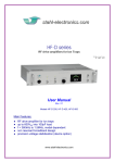
QUAD 1-10 ______ Rotating Wall Drive for Ion Compression in Traps 20 - Jan - 2009 Data Sheet Rev. 2.2 Electronics for Science and Research Kellerweg 23, D - 67582 Mettenheim Germany www.stahl-electronics.com QUAD 1-10 Rotating Wall Drive - User Manual, Rev 2.1 General Information and Overview The QUAD 1-10 rotating wall drive is designed to create a rotating dipole or quadrupole electrical field inside a Penning Ion Trap. The resulting electrodynamical “rotating wall” enables fast compression of big ion clouds (see refs. [1], [2], [3]) after loaded into the trap. The QUAD 1-10 represents a tool to handle a wide range of ions/plasma rotation frequencies with respect to this novel application. As indicated in the picture below, an input signal, for instance a sinusoidal wave, will be converted into an amplified 4-channel signal. All 4 channels have a phase relation of 90° and equal amplitude. In case a 4-segmented ring electrode is connected, a rotating dipole field is created, whereas an 8segmented ring will provide a rotating quadrupolar field. The nominal frequency range, in which a proper 90° phase shift from output to output is provided, covers about 80kHz to 10MHz, at a nominal output amplitude range of 0Vpp to 10Vpp. The signal input is 50 Ohm compatible, whereas the outputs do not require a 50 Ohm termination. Fig. 1 Ion trap setup including a QUAD 1-10 rotating wall drive Functional Principle and Block Diagram The following picture displays the internal structure. After passing through an input amplifier, which performs a frequency response correction, an analog precision phase shift hybrid network creates 4 individual output lines having 90° of phase shift and equal amplitude. In principle any signal at the input, which lies within the nominal frequency and voltage range (80kHz to 10MHz; 0 … 2Vpp) is suited for this application and will experience a 4-fold 90° phase shift. The internal analog phase shift network acts as a linear device in the electrodynamical sense and does not rely on non-linear effects or mixing processes. For complex input signals, having many frequency components in the spectrum, all components will be phase-shifted individually without interfering with other spectral components. Fig. 2: Internal structure of the QUAD 1-10 device 2 www.stahl-electronics.com phone: +49 6242-504882, fax: +49 6242 504884 QUAD 1-10 Rotating Wall Drive - User Manual, Rev 2.1 This linear operation represents a considerable advantage over other ways of creating a rotating wall drive, like using several individual function generators. There is freedom to apply any signal in the nominal frequency and amplitude range in a direct way without changing the device configuration or reprogramming. Also complex spectra like SWIFT functions, sweeps, artificial noise and multi-tone signals may be applied. Four output buffers drive the outputs at the rear side, following the internal phase shift network and allow interfacing to an ion trap. A 50 Ohm termination at the output lines is not recommended. As an additional feature, a common DC-Offset-Input (rear side) for DC-Bias allows floating the 4 outputs up to +/-150 V on an additional DC level. LED indicators on the front plate show the presence of a suitable input signal and the corresponding output voltage level. Fig. 3 Graphical illustration of electric dipole/quadrupole creation. For an electric dipole, connect the lines (A,B,C,D) as shown in the left picture, for a quadrupole as shown in the right picture. Please observe the correct order while connecting the cables. Shading in the pictures above illustrates the momentary electric potential (dark: low; light: high). Elements on front and rear plate Front Side Power Switch Input & Power-On LED LED bargraph indicating output amplitudes rotating phase indicator Fig. 4.1: Front plate DC Offset-Input 4 Outputs, 90°-shifted Fig. 4.2: Rear plate Ventilation Fan Mains Switch 3 www.stahl-electronics.com phone: +49 6242-504882, fax: +49 6242 504884 QUAD 1-10 Rotating Wall Drive - User Manual, Rev 2.1 Specifications Parameter Ext. Power Supply Input (BNC connector) Input Impedance Voltage Range Coupling Mode Frequency Range Outputs (BNC connectors) Functionality Voltage Range Amplitude mismatch between outputs spec. Value Condition/Remark AC input 230VAC , 50Hz. Typical Power Consumption: 35W The power entry module is EMI/RFI-filtered. 60 Ohm 0...2Vpp AC 80 kHz … 10 MHz 4 Outputs, 90° Phase Shifted 0...10Vpp nominally max. 12Vpp (overrange) output load 150pF each channel ‘’ f = 80 kHz .. 10 MHz typ. < 0.25dB max. 5° typ. 2.5° ‘’ ‘’ nominally 5x (14.0dB) typ. 0.5dB f = 80 kHz .. 10 MHz, each channel 150pF loaded ‘’ Nominal Freq. Range 80kHz...10MHz output load 150pF each channel Rotating Phase Indicator Wideband Output Noise, any channel Ext. DC-Offset range min. signal level typ. 10mVpp f = 80 kHz .. 10 MHz 1.7mV rms bandwidth 1kHz … 60MHz Phase mismatch between outputs Input/Output Voltage Gain Gain flatness over freq. range Storage Temperature Recommended Operating Humidity & Temperature External Magnetic Field Physical Dimensions Weight 150VDC remark: the applied external offset (DC) voltage is internally added to the ac output voltages -55C° to +105C° noncondensing relative humidity; temperature between +15°C and +30°C max. 10mT approx. 485mm x 92mm x 310mm approx. 3.5 kg External magnetic field at metal case must never exceed value. Typical performance charts Gain flatness versus frequency; amplitudes are averaged over all output channels (A,B,C,D) 4 www.stahl-electronics.com phone: +49 6242-504882, fax: +49 6242 504884 QUAD 1-10 Rotating Wall Drive - User Manual, Rev 2.1 Phase error vs. frequency. Graph shows deviation from the nominal 90° shift between output channels load on each channel: 150pF // 1MOhm; measurement device: oscilloscope TDS 210 (Tektronix) Amplitude mismatch vs. frequency; graph shows voltage ratios between output channels load on each channel: 150pF // 1MOhm; measurement device: oscilloscope TDS 210 (Tektronix) Device Variety Currently there are two main members of the QUAD 1-X series device family: Device Name Versions Characteristics Quad 1-5 Frequency Range 100kHz…5MHz Output Amplitude up to 20Vpp (at low frequencies) Quad 1-5b Frequency Range 100kHz…5MHz Output Amplitude 20Vpp (entire frequency range) Quad 1-10 Frequency Range 80kHz…10MHz Output Amplitude 10Vpp (entire frequency range) Quad 1-5 Quad 1-10 Literature : [1] X.-P. Huang, F. Anderegg, et al., Phys. Rev. Lett. 78, 875 (1997) [2] E.M. Hollmann et al., Phys. Plasmas 7, 2776 (2000) [3] Funakoshi et al.; Phys. Rev. A 76, 012713 (2007) 5 www.stahl-electronics.com phone: +49 6242-504882, fax: +49 6242 504884