1
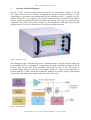
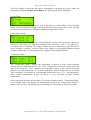
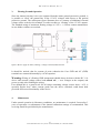
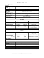
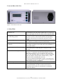
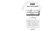
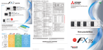
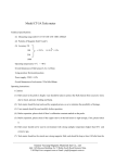
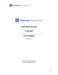
DC1_10ref_Manual.doc 12 - August - 2009 User Manual Rev. 1.1 Electronics for Science and Research Kellerweg 23, D - 67582 Mettenheim Germany www.stahl-electronics.com DC 1-10 User Manual, Rev 1.1 TABLE OF CONTENTS 1. Overview and Block Diagram………………….………………………………... 3 2. Operation and Control Elements ………………………………………………... 4 3. Floating Ground Operation……………………………………………………... 6 4. Maintenance………………………………………….…………………………. 6 5. Specifications…………………………………………………………………… 7 6. Safety Hints…………………………………………………………………….. 8 Declaration of Conformity ………………………………………………………… 9 2 www.stahl-electronics.com phone: +49 6242-504882, fax: +49 6242 504884 DC 1-10 User Manual, Rev 1.1 1. Overview and Block Diagram The DC 1-10ref precision voltage reference provides two fixed stable voltages of 1V and 10V, which can be used for reference or adjustment purposes. Absolute precision is in the 20ppm-range, low thermal and temporal drifts (about 1ppm/Kelvin and < ½ ppm/hr.) are key features. Unlike DC power supplies, the available output currents are limited to small values, and the outputs are optimized for short and long term stability, low ripple, low noise and low temperature drift. This source can be floated, e.g. for combination with other fixed variable voltage sources. The device is housed in a 20cm wide shielded metal case. figure 1: Perspective view The subsequent figure illustrates the device’s internal structure. A high precision solid-state fixed voltage source is embedded in a temperature and drift stabilized environment and is used as input for the main buffer amplifier, which delivers 10V to the 10V-output. A precision voltage divider creates the second output voltage 1V, which is also buffered by a second amplifier. A RISC-based microcontroller monitors the output voltages and internal temperatures and displays these data on the front side LCD screen. figure 2: Block diagram 3 www.stahl-electronics.com phone: +49 6242-504882, fax: +49 6242 504884 DC 1-10 User Manual, Rev 1.1 2. Operation and Front Plate Elements figure 3: Elements on the front plate Turn on the device using the rear side mains-switch. The internal circuitry will run up and is after roughly 60 seconds (warm-up phase) ready to operate. The 10 V output voltage will be available between the 10V-Output terminal (4mm “banana” socket) and the 0V(GND)output terminal. Correspondingly 1 V is provided between the 1V-Output terminal and the 0V(GND)-output terminal. The Case GND (= protective GND) terminal is connected with the protective ground line of the rear side 230Vac mains socket. The internal circuitry, connected to the 0V/1V/10V output terminals is generally floating versus Case GND. Still, it should be noticed, that for reasons of noise reduction the Case GND and 0V-terminal are connected internally by a 47nF capacitor. In case, that no “floating voltage“ (see below) is applied between the 0V(GND) and Case GND terminal, both should be connected by a short cable to maintain best stability. All outputs are regarded as outputs only. In no case an external voltage source (neither ac nor dc) must be applied, which could force an excessive current to flow into the device terminals. The 10V / 1V terminals can both sink and source currents. This gives the user the possibility to apply an offset voltage to the 0V (GND) terminal, usually called “floating ground” operation, as described in the chapter below. It allows also to connect a load between the 10V and 1V terminals, providing 9V of stable voltage difference. The output impedance of both outputs is 10.0 Ohms nominally, given by internal protection resistors. Even though this is not regarded as a high impedance, its influence on high precision measurements must be considered. For instance connecting a digital multimeter with 10M input resistance will lead to a decrease of about 1ppm (10-6) in output voltage because of the resistive voltage divider effect. The outputs are generally not designed to deliver high electrical currents. A current of more than +/-500µA (1V-output) or +/-5mA (10V-output) will cause an error indication (see below) on the LCD display. If, for example, an absolute precision of 10-5 with respect to the output voltage is requested, the current load must not exceed 1µA at the 1V-output, or 10µA at the 10V output. Apart from these accuracy considerations, permanent currents of up to +/- 4mA (1V or 10V terminal) are admissible. 4 www.stahl-electronics.com phone: +49 6242-504882, fax: +49 6242 504884 DC 1-10 User Manual, Rev 1.1 The LCD display on the front side shows informations concerning the device status. By iteratively pressing the Display Mode Button, the following modes are displayed: Normal Mode: Indicates general operation. In case no error is detected (see “Status Mode”, below) and the button is not pressed, the backlight of the display becomes darker after about 1 min., in order to decrease the internal power dissipation and related temperature effects. Output Status Mode: Shows the status of the outputs. “Ok” will be displayed as long as the two output voltages are deviate no more than 0.5% from their nominal value. Otherwise “10V or 1V output exc.” (exceeded) will be indicated. The purpose of this function is primarily to warn the user of severe deviation, caused by excessive loads at the outputs, by accidentally applied external voltages or short cuts. It is not understood as a high precision voltage indicator. Temperature Mode The “Temperature Mode” displays the temperature in degrees Celsius, being internally measured at two different positions. The “Case” temperature is measured closely to the rear side of the metal case, “Ref.” indicates the temperature closely to the internal solid state reference. In normal operation 37°C at both temperature sensors should never be exceeded. That corresponds to operation in environmental temperatures up to 27°C (air temperature). Please contact manufacturer in case the device is to be operated at higher ambient temperatures. In case an output deviation of more than 0.5% is detected while being in “Temperature Mode” or in “Normal Mode”, the display will automatically switch to the “Output Status Mode” in order to show an error. The display does intentionally not switch back to the previous mode. 5 www.stahl-electronics.com phone: +49 6242-504882, fax: +49 6242 504884 DC 1-10 User Manual, Rev 1.1 3. Floating Ground Operation Since the internal circuitry is dc-wise separated from the mains ground (protective ground), it is possible to “float” the ground line of the 1V/10V voltages with respect to the general protective ground. The subsequent figure illustrates how to connect an additional external voltage source to the device terminals, in order to achieve a “floating” of the 1V/10V outputs. The standard rating of maximum floating voltage is 125Vac + dc. Please contact manufacturer in case higher voltages are required. figure 4: How to apply an offset (“floating”) voltage to the 0V(GND) terminal It should be noticed, that for reasons of noise reduction the Case GND and 0V (GND) terminals are connected internally by a 47nF capacitor. Warning: Wiring of a floating GND arrangement should always be done with the DC 1-10 device and external voltage source both turned off ( = zero voltages at the outputs) and power-up only after finishing the wiring. Even though this is a general rule for all setups containing voltage sources above ~10V, it specially applies here, where current peaks into the device terminals could harm both precision and correct functionality of the device. 4. Maintenance Under normal operation in laboratory conditions, no maintenance is required. Latest after 3 years of operation a re-adjustment of the internal calibration settings is recommended. This servicing should be performed by the manufacturer. 6 www.stahl-electronics.com phone: +49 6242-504882, fax: +49 6242 504884 DC 1-10 User Manual, Rev 1.1 5. Specifications Parameter Output Voltage 10V Output 10 V nominally 1V Output 1V nominally Output Connectors Maximum Admissible Permanent Output Current 10V Output or 1V Output Output Reference Ground Terminal denominated “0V” Maximum Floating Voltage Reference Ground vs. Protective Ground Recommended Ambient Temperature 4mm female, “banana” min. +/-4mA transient max. 100 mA, T < 0.1s Both outputs share a common GND, which is decoupled from protective ground by 47nF +/-125 V higher rating on request 21°C…27°C 10V Output Initial Accuracy Aging Temperature Coefficient Short Term Fluctuations T = 1 min. T = 1 hour Output Resistance typical maximum boundary conditions 15 ppm 25 ppm 2.5 ppm / yr 0.6 ppm / K 10 ppm / yr 1.6 ppm / K standard calibration procedure, T = 25°C +/-2°C permanent operation *) T = 25°C +/-2°C 0.06 ppm 0.11 ppm 0.18 ppm 0.3 ppm 10.0 Ohm 9.5 … 10.5 Ohm constant ambient air temperature, no air flow, no mechanical vibrations 1V Output Initial Accuracy Aging Temperature Coefficient Short Term Fluctuations T = 1 min. T = 1 hour Output Resistance Storage Temperature Magnetic Field Operating Humidity & Temperature AC Power Supply Case dimensions Weight typical 30 ppm maximum 60 ppm to be determined 1.0 ppm / K to be determined 2.0 ppm / K 0.5 ppm 1 ppm 1.5 ppm 3 ppm 10.0 Ohm 9.5 … 10.5 Ohm boundary conditions standard calibration procedure, T = 25°C +/-2°C permanent operation *) T = 25°C +/-2°C constant ambient air temperature, no air flow, no mechanical vibrations -55C° to +105C°. max. 10 mT admissible noncondensing humidity, temperatures between +10°C and +27°C AC input power 230VAC at 50Hz. The power entry module is EMI/RFI-filtered. Fuse: slow blow 0.8 A. Typical Power Consumption: 8 W 183 mm x 105 mm x 210 mm 1.58 kg *) drift is achieved after first 2000 hours of operation. 7 www.stahl-electronics.com phone: +49 6242-504882, fax: +49 6242 504884 DC 1-10 User Manual, Rev 1.1 Front and Rear Side View figure 5: Front and rear side view 6. Safety Hints Rear side switch turns device completely off This equipment must be connected to an earth safety ground Do not modify the unit Do not operate in wet/damp conditions Disconnect power before servicing Beware of external magnetic fields No outdoor operation No terminal overloads If the device is not in use for a longer time, it is recommended to turn the mains switch at the rear side off, in order to prolongate the life time and to reduce temporal drifts. This product is grounded through the grounding conductor of the power cord. To avoid electrical hazard, the grounding conductor must always be connected to protective earth ground. Do not make electrical or mechanical modifications to this unit, which are not authorized by the manufacturer. To avoid electric shock hazard, do not operate this product in wet or damp conditions. Protect the device from humidity or direct water contact. To avoid electric shock hazard, disconnect the main power by means of the power switch and power cord prior to any servicing. External magnetic fields can impair, damage or even destroy this device. A maximum external field strength of 10mT is admissible and must never be exceeded at any point of the device. This statement applies for static as well as alternating fields. If in doubt, check possible external field e.g. with a hall probe before switching the device on. In case an external field strength of 10mT is exceeded, once or permanently, the device may overheat, cause fire hazard or cause excessive power consumption. Outdoor operation of the device is not admissible. Keep all currents, flowing into the device terminals below their specified limits, in order to ensure correct device performance and in order to avoid thermal overload and possible fire hazard. 8 www.stahl-electronics.com phone: +49 6242-504882, fax: +49 6242 504884 DC 1-10 User Manual, Rev 1.1 DECLARATION OF CONFORMITY Manufacturer's Name: Dr. Stefan Stahl - Electronics for Science and Research - Manufacturer's Address: Kellerweg 23 67582 Mettenheim Germany. Declares, that the product Product Name: Model Number: DC 1-10ref - Ultrastable Precision Voltage Source DC 1-10ref Conforms to the following European Directives: The product herewith complies with the requirements of the: 1. Low Voltage Directive 73/73EEC; 2. EMC Directive 89/336/EEC (including 93/68/EEC) and carries the CE Marking accordingly Date of Issue __________________ 22. June 2008 CEO 9 www.stahl-electronics.com phone: +49 6242-504882, fax: +49 6242 504884