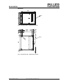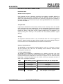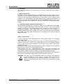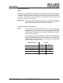
1
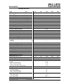
AS 60-200KVA
TECHNICAL DATA
Type
AS
UPS rated output
kVA
(cos ϕ = 0,8)
Rectifier input data
Rated current without battery charging
A
Rated output power without batt. charging kVA
Max. current at highrate batt. charging
A
Max. output power
kVA
Power factor cos ϕ (typical)
Rated voltage
Rated frequency
Required fuse protection Diazed/NH Type GL A
Current harmonic distortion
Starting time incl. precharge
Link circuit - battery
Recommended number of cells
max. DC current
A
Rated batt. charging current of 10min-battery A
max. battery charging current
A
Charging current pre-setting
– normal
A
– high rate
A
Continuos charging voltage
Equalising charging voltage
Discharge voltage
Voltage tolerance
Residual ripple
Charging characteristic
Inverter output data
Rated active power (cos ϕ = 1)
Rated current (cos ϕ = 0.8)
Rated current (cos ϕ = 1)
Rated voltage
Rated frequency
Voltage tolerance
– static
– 50% unbalanced load
– 100% unbalanced load
– dynamic with 100% load change
60
60
80
80
84
58
96
67
109
75
127
88
125
162
4
26
192
215
6
34
318
10
52
160
160
200
200
207
143
246
170
255
177
306
212
250
315
2 x 198
2 x 203
2 x 253
2 x 12
2 x 14
2 x 33
2 x 42
I10
I5
2,23 – 2,3
2,4
1,65
± 1%
≤ 1%
DIN 41773
48
87
70
64
116
92
96
173
139
128
231
185
160
289
231
3/N 400 V ± 5% adjustable
50 Hz
± 1%
± 1%
± 3%
< 5%
< 10 ms
Settling time
Angular deviation
– symmetrical load
– 50% unbalanced load
– 100% unbalanced load
Frequency tolerance
– line commutation
– self commutation
AS IV_Tech_Data.doc 09.04.02
156
108
186
129
≥ 0,97
3/N 400 V ± 15%
50 Hz ± 5%
160
200
≤ 5%
30 s
V/Cell
V/Cell
V/Cell
kW
A
A
120
120
< 1°
< 2°
< 3°
± 1%
± 0,1 %
We reserve the right to change without notice!
1
AS 60-200KVA
Type
AS
UPS rated output
kVA
(cos ϕ = 0,8)
Distortion factor (EN 50091-1)
– linear load
– non linear load
Crestfactor
Overload
– 3ph
– 1ph
Short-circuit characteristics
– 3ph
– 1ph
Inverter efficiency with rated load
Automatic Bypass
Rated voltage
Rated frequency
Overload capacity
– 10 min
– 100 ms
Inverter/Bypass changeover time
– inverter fault
– overload or man. operation
Bypass/Inverter changeover time
Required fuse protection Diazed/NH Type GL A
General Data
Overall efficiency
– 100% load
%
– 75% load
%
– 50% load
%
– 25% load
%
Power dissipation
– 100% load
kW
– 75% load
kW
– 50% load
kW
– 25% load
kW
3
Air rate required
m /h
Noise level at a distance of 1m
Permiss. ambient temperature
Relative humidity
Installation altitude
Humidity class
Protection type
Insulation group
Radio interference level
Dimensions
– width
– depth
– height
Weight
Floor loading
AS IV_Tech_Data.doc 09.04.02
kg
2
kg/m
60
60
80
80
120
120
160
160
200
200
< 1%
< 5%
≥3
150 % 30 s, 125 % 10 min
220 % 30 s, 180 % 10 min
200 % 20 ms, 150 % 3 s
350 % 20 ms, 260 % 3 s
98 %
400 V
50 Hz
150 %
1000 %
100
125
2 ms
0 ms
0 ms
200
91
92
92
92
92
4,75
5,6
8,5
10,3
13
2000
2000
ca. 900
804
895
1400
ca. 900
250
315
2500
2500
2500
67 dB(A)
0 – 40°C
daily average ≤ 35°C
5 % - 95 % without condensation
<1000 m above mean sea level without power reduction
DIN/IEC 721 2-1-09/86
IP 21 (DIN/VDE 0470 part 11/92 IEC 529)
DIN/VDE 0110, Overvoltage category 2, Fouling factor 2
EN 50091-2 Standard class A
We reserve the right to change without notice!
ca. 1100
see section 0
993
815
1802
ca. 850
ca. 850
2
AS 60-200KVA
Type
UPS rated output
(cos ϕ = 0,8)
Paint finish
Cable connection
AS
kVA
60
60
80
80
120
120
160
160
200
200
RAL 7035 textured
from bottom
Specifications complied with:
DIN/VDE 0100
DIN/VDE 0103
DIN/VDE 106 part 1 IEC 536
DIN/VDE 0110 01/89
DIN/VDE 0160
DIN/VDE 470 part 1 11/92 IEC 529
DIN/VDE 0510 part 2 10/97
DIN/VDE 0558 part 5 09/88 IEC 146-4
DIN/VDE 0558 part 6 04/92 IEC 146-5
DIN EN 50091-1, VDE 0558 part 510
DIN EN 50091-1-1, VDE 0558 part 511
DIN EN 50091-2, VDE 0558 part 520
DIN/IEC 721-2-1-09/86
Protection against electric shock after VBG 4
DIN 41772
DIN 45635 part 1 04/84
IEC 801
Battery: DIN/VDE 0510 part 2 07/86
AS IV_Tech_Data.doc 09.04.02
We reserve the right to change without notice!
3
AS 60-200KVA
Dimensions
Air outlet
(1396)
Air inlet
A
A
(804)
793
Air inlet
880
15
895
Sectional A - A
( also shown space requirement )
ca. 861
793
34
150
34
Cable entry
(input or output)
bottom
510
148 87
81,5
Fluchtweg n.
VDE 100 Teil 729
Escape acc. to
VDE 100 Piece 729
(525)
294
Open door angle 180°
Fig. 1 APOSTAR 60 – 120 kVA Dimensions and space requirements
AS IV_Tech_Data.doc 09.04.02
We reserve the right to change without notice!
4
AS 60-200KVA
Air outlet
A
A
1802
Air inlet
Air inlet
778
993
800
15
Air outlet
A-A
(also showing the space requirement)
570
100
800
650
92
16
60
Ø
790
Fluchtweg n.
VDE 100 Teil 729
100
294
100
Escape acc. to
VDE 100 piece 729
(575)
140
87
Cable entry/
Cable output bottom
100
25
60
940
200
25
Aperture angle of the doors 180°
Doors can be unhinged with an aperture angle of more then 90°
Fig. 2 APOSTAR 160 – 200 kVA Dimensions and space requirements
AS IV_Tech_Data.doc 09.04.02
We reserve the right to change without notice!
5
AS 60-200KVA
Baseframe
850
790
690
Door
Fig. 3 APOSTAR 60 – 120 kVA baseframe
570
100
60
650
60
25
100
100
Door
Ø
790
100
25
940
16
Fig. 4 APOSTAR 160 – 200 kVA baseframe
AS IV_Tech_Data.doc 09.04.02
We reserve the right to change without notice!
6
AS 60-200KVA
INSTALLATION AND CONNECTIONS
Installation notes
Goods inwards inspection
Final inspection ensures satisfactory mechanical and electrical condition before that
APOSTAR leaves the factory. Immediately after the equipment arrives, please check
whether any freight damage has occurred and if necessary, bring this to the attention of
the freight operator. In no circumstances put a damaged APOSTAR into service before
your have consulted us!
Transportation
If required, the APOSTAR and the battery cubicles can be moved by means of a fork-lift
or lift truck. Moving by crane should only be used in exceptional circumstances and only
after consulting us. Ensure that the equipment is only transported upright and not tilted or
turned over. Always avoid sharp impacts. Where possible leave the equipment in its
original packing when moving it. This provides the best possible protection against
damage.
Storage
The equipment should be stored in a dry, well-ventilated room that is free of aggressive
materials. Where possible, the original packing should not be removed during storage. In
no circumstances must the APOSTAR be left stacked or stored outside!
Choice of installation site
The APOSTAR is not designed for mounting against a wall, i.e. a clearance of at least
150 mm should be left to the wall. The following criteria should be observed when
selecting the installation site:
a. Floor loading capacity
The weight of the equipment is distributed over a relatively small area; care must
therefore be taken to en-sure that the floor loading capacity is adequate. The exact value
can be obtained from the table below. If necessary, the support area can be increased by
interposing a suitable load distribution rack. Please consult your architect, the clerk of
works or us if you require assistance.
Type
AS IV_Tech_Data.doc 09.04.02
Floor loading capacity
Compressive loads per unit area per feet
2
1,26 kg/cm
2
1,26 kg/cm
2
1,55 kg/cm
AS 60 kVA
0,128 kg/cm
AS 80 kVA
0,128 kg/cm
AS 120 kVA
0,157 kg/cm
AS 160 kVA
0,11 kg/cm
AS 200 kVA
0,11 kg/cm
2
2
2
2
front: 3,5 kg/cm / back: 7 kg/cm
2
front: 3,5 kg/cm / back: 7 kg/cm
We reserve the right to change without notice!
2
2
2
2
7
AS 60-200KVA
b. Baseframe
The necessary dimensions for constructing a base-frame, if required, can be found in
Fig. 3 - Fig. 4.
c. Space requirements
As already stated, the APOSTAR cannot be installed with the rear side against a wall. A
clearance of at least 150 mm should be left. About a metre clearance should be left in
front of the unit to provide unimpeded access to the cubicle. Local or general safety
regulations, e.g. escape routes as per VDE 0100, part 729, should also be observed. A
clearance of at least 40 cm should be left above the APOSTAR to allow the warm air to
be freely exhausted. In no circumstances must the air inlet and air outlet be covered or
blocked.
d. Installation altitude, temperature and humidity
The APOSTAR is designed for an installation altitude of up to 1000 metres above mean
sea level, an ambient temperature of 0 to 40°C (daily average ≤ 35°C) and a relative
humidity of up to 90 %. The optimum temperature is around 20°C. Please consult us if
planning an installation above 1000 metres. Please ensure that any existing airconditioning plant meets these conditions and is also able to remove the unit's dissipated
heat. Details are shown in the technical data. The cooling air must always be free of
aggressive agents.
Battery – general notes
As special equipment for the APOSTAR UPS, PILLER supplies battery sets for bridging
mains failure periods.
If the system power and required back-up time allow, the sealed lead-acid batteries are
built into a cubicle that is matched to the UPS cubicle and can be in-stalled immediately
next to it. But a more remote installation is also possible. Please discuss your special
requirements with us.
The optimum ambient temperature for the batteries is 20 °C. Temperatures considerably
higher than this shorten the service life of the batteries.
If open batteries are used, a specially-equipped battery room must be provided. This
must meet the various safety requirements. Contact your appropriate local authority for
further details. A battery installation should also meet DIN VDE 0510 procedures.
Please note that batteries have only a limited storage life. Please contact us or the battery
manufacturer if you intend storing the battery sets for more than a few days.
WARNING The battery sets for the APOSTAR system are charged up when delivered.
Improper handling can cause injuries or damage. When connecting the
battery sets ensure that the connecting terminals are "dead”, e.g. by
opening the fuse-disconnector. Check that the circuit is dead before making
connections.
AS IV_Tech_Data.doc 09.04.02
We reserve the right to change without notice!
8
AS 60-200KVA
Electrical connections
General
Connections for the APOSTAR are provided by terminal strips located in the lower third of
the cubicle. The cables can be brought up to the cubicle from all four sides and led in
through the bottom of the cubicle. A false floor in the installation room is not necessary.
The tables and drawings hereafter indicate the cable connection points and the cable
dimensions according to DIN VDE 0298.
IMPORTANT
You must ensure that the phases of the a.c. connections (clockwise
rotating field) and the polarity of the battery connections are correct, as
incorrect connections can cause damage to the equipment.
Terminal assignment and cable sizes
NOTE
1. The battery cables should not be longer than 15 m; the voltage drop
not more than 1.5 %. Please consult us if you are unable to meet these
requirements. Page 20 shows the recommended cable types. When
determining the cable lengths bear in mind that about 0.50 m of cable is
required inside the cubicle.
2. In the event of a fault in the UPS set, e.g. short-circuit, the input fuse of
the unit must trip before the mains fuse since only then is transfer to the
bypass mode possible without a break. Diazed/l.v.h.r.c. type GL fuses
should therefore be used as mains fuses. The minimum fuse rating can
be obtained from the table hereafter.
UPS-power (kVA)
AS IV_Tech_Data.doc 09.04.02
Fuse (A)
Mains 1
Mains 2
60
125
100
80
160
125
120
200
200
160
250
250
200
315
315
We reserve the right to change without notice!
9
AS 60-200KVA
The table hereafter shows the power cables required for the APOSTAR UPS according to
DIN VDE 298.
Maximum currents and power cables
Temperature factor: 35 °C = 0,94
Cable tray with free air circulation, spacing = cable diameter d
UPSType
Mains 1
1
L1-L3, N, PE
60
96 A
1 x NYCWY 4 x 35RM/16
87 A
each 1 x NYCWY 4 x 35RM/16
162 A
1 x NYY-0 4 x 16RE
80
127 A
1 x NYCWY 4 x 50SM/25
115 A
each 1 x NYCWY 4 x 50SM/16
215 A
1 x NYY-0 4 x 25RE
120
186 A
1 x NYCWY 4 x 95SM/50
173 A
each 1 x NYCWY 4 x 95SM/50
318 A
1 x NYY-0 4 x 50SM
160
246 A
1 x NYCWY 4 x 120
231 A
each 1 x NYCWY 4 x 120
2 x 203 A
2 x NYY-0 4 x 50SM
200
306 A
2 x NYCWY 4 x 70
289 A
each 2 x NYCWY 4 x 50
2 x 253 A
2 x NYY-0 4 x 50SM
Mains 2
L1-L3, N, PE
Output
2
L1-L3, N, PE
Battery
3
+/-
The following table should be noted when laying parallel cables:
Temperature factor: 35 °C = 0,94;
Cable installation factor: 3 cables in parallel = 0,8; total = 0,752
2
Cross-section (mm )
10
16
25
35
50
70
95
120
150
Loadability incl. factor 0,752 in A
Multi-conductor cable
Single-conductor cable
DC
AC
DC
AC
49
45
59
49
67
60
79
67
89
78
105
89
109
98
131
109
132
119
159
132
168
152
202
168
204
183
249
204
236
212
290
236
271
243
332
271
The protective earth and N connection of the UPS should be provided by both infeeds so
that the cables have full redundancy.
For symmetry, when possible and if permitted, 3-core cable type NYCWY (full crosssectional sheath) and a separate protective conductor should be used.
1
2
3
In case of large capacity batteries and/or high-rate charging option, please consult us about the cable layout.
With only one network input, the same cable cross-section as used for Mains 1 should be selected for the output.
In any case all battery cubicles or racks must be grounded.
AS IV_Tech_Data.doc 09.04.02
We reserve the right to change without notice!
10
958
AS 60-200KVA
Batt.
24 6
78 9
N3
1 3 5
N2
X1
N1
Mains 2 Mains 1 Output
+-
1 2
X4
350
PE
127
250
25
78
41
254
18
Fig. 5 Cabinet terminal arrangement APOSTAR 60 - 80kVA
Terminal X1 2
4
6
N
UPS-Input (Mains 1)
UPS-Input (Mains 1)
UPS-Input (Mains 1)
UPS-Input (Mains 1)
L1
L2
L3
N2
Terminal X1 1
3
5
N
Bypass-Input (Mains 2)
Bypass-Input (Mains 2)
Bypass-Input (Mains 2)
Bypass-Input (Mains 2)
L1
L2
L3
N1
Terminal X1 7
8
9
N
UPS-Output
UPS-Output
UPS-Output
UPS-Output
L1
L2
L3
N3
Terminal X4 1
2
Battery-Input
Battery-Input
+
–
AS IV_Tech_Data.doc 09.04.02
We reserve the right to change without notice!
11
954
AS 60-200KVA
Batt.
2 4 6
78 9
N3
1 3 5
N2
X1
N1
Mains 2 Mains 1 Output
+-
1 2
X4
350
PE
90
310
55
243
47 18
31
Fig. 6 Cabinet terminal arrangement APOSTAR 120kVA
Terminal X1 2
4
6
N
UPS-Input (Mains 1)
UPS-Input (Mains 1)
UPS-Input (Mains 1)
UPS-Input (Mains 1)
L1
L2
L3
N2
Terminal X1 1
3
5
N
Bypass-Input (Mains 2)
Bypass-Input (Mains 2)
Bypass-Input (Mains 2)
Bypass-Input (Mains 2)
L1
L2
L3
N1
Terminal X1 7
8
9
N
UPS-Output
UPS-Output
UPS-Output
UPS-Output
L1
L2
L3
N3
Terminal X4 1
2
Battery-Input
Battery-Input
+
–
AS IV_Tech_Data.doc 09.04.02
We reserve the right to change without notice!
12
78 9
N3
Mains 3
X1
PE
PE
207
333,5
24 6
N2
X1 1 3 5
N1
Mains 1 Mains 2
Batt1. +
Batt1. Batt2. +
Batt2. -
1375
AS 60-200KVA
100
216
274
108 52 108 100
36
Fig. 7 Cabinet terminal arrangement APOSTAR 160 – 200 kVA
Terminal X1 2
4
6
N
UPS-Input (Mains 1)
UPS-Input (Mains 1)
UPS-Input (Mains 1)
UPS-Input (Mains 1)
L1
L2
L3
N2
Terminal X1 1
3
5
N
Bypass-Input (Mains 2)
Bypass-Input (Mains 2)
Bypass-Input (Mains 2)
Bypass-Input (Mains 2)
L1
L2
L3
N1
Terminal X1 7
8
9
N
UPS-Output
UPS-Output
UPS-Output
UPS-Output
L1
L2
L3
N3
Terminal X4 1
2
Battery-Input
Battery-Input
+
–
AS IV_Tech_Data.doc 09.04.02
We reserve the right to change without notice!
13
AS 60-200KVA
Terminal types and dimensions
The conductor cross-sections of the UPS terminals (box terminals or cable lugs) are
shown in the following table.
UPS-Type
Cable type
60 kVA
80 kVA
120 - 200 kVA
rigid
flexible
rigid
flexible
rigid
flexible
2
25
35
35
50
70
70
2
95
95
150
150
240
240
min.
mm
max.
mm
stripping the cables
mm
30
38
38
Neutral conductor and PE conductor connections
The PE connections and the N-connections of the external manual bypass are attached
to the corresponding copper bars by means of M8 screws.
AS IV_Tech_Data.doc 09.04.02
We reserve the right to change without notice!
14
AS 60-200KVA
Connection for external operation and monitoring
Customer interface card, terminal strip X1
Terminal strip X1 is used by the customer to match the UPS to his own electronic
installation, such as UPS-blocked circuit, remote control signals and Diesel stand-by
generating set.
UPS blocked/Off
If an external contact is to be added, then the links between EPOint X1.1 and EPOext
X1.2 should be removed and replaced by an N/C contact of the external UPS-blocked
button.
Remove link for external
“UPS blocked”!
Ext.
APOSTAR off
1
X1
2
3
4
Remote on
5
GND
6
7
8
Remote Bypass on
9
10
11
12
UPS Diesel mode
13
14
15
16
Battery charging off
17
18
19
Remote off
20
21
Ext. Output breaker
is open
Fig. 8 Terminal strip A230 X1
External manual bypass
General
Two variants are available for the UPS installation. The standard version, in which the
manual bypass (bypass contactor) is built into the set, and an extended version in which
an additional, external manual bypass can be supplied. This is located, along with
additional necessary isolators, in a separate adjacent cubicle.
The decisive advantage of this extended version is that the UPS cubicle can be
completely isolated, thus allowing the necessary maintenance and repair operations to be
carried out safely in the UPS cubicle, without having to interrupt the supply to the load.
AS IV_Tech_Data.doc 09.04.02
We reserve the right to change without notice!
15
AS 60-200KVA
Installation and connections
The auxiliary cabinet for the external manual bypass is placed immediately to the right or
the left of the UPS cabinet. To do this, remove the right-manual side panel of the UPS
cabinet. This is used as the side panel of the auxiliary cabinet.
Lead the cables through the openings in the bottom of both cabinets and attach them to
the corresponding terminals in the UPS cabinet.
Q500
Q50
Bypass input
(Mains 2)
X50
Q60
UPS
Mains supply
(Mains 1)
X60
Load
X10
Fig. 9 External manual bypass
AS IV_Tech_Data.doc 09.04.02
We reserve the right to change without notice!
16
AS 60-200KVA
Battery cabinet connections
When several battery cabinets are interconnected, one battery set can be housed in
several cabinets (series connection) or several sets can be connected in parallel to
increase the capacity.
Battery cabinet
+
Battery cabinet
+
4
-
2
1
+
+
-
1
-
+ +
-
-
-
-
2
-
=1 +
X4
UPS
Fig. 10 Battery cabinets connected in series
Battery cabinet
+
Battery cabinet
+
4
-
2
1
+
+
-
1
2
=1 +
X4
-
-
+ +
UPS
Fig. 11 Battery cabinets connected in parallel
AS IV_Tech_Data.doc 09.04.02
We reserve the right to change without notice!
17