1
APCUPSD User Manual
Adam Kropelin
Kern Sibbald
Apcupsd is a UPS control system that permits orderly shutdown of your computer in the event of
a power failure.
March 28, 2014 23:31:53
This manual documents apcupsd version 3.14.x
Copyright © 2004-2014 Adam Kropelin
Copyright © 1999-2005 Kern Sibbald
Copying and distribution of this file, with or without modification, are permitted in any medium without
royalty provided the name Apcupsd, the copyright notice, and this notice are preserved.
Apcupsd source code is released under the GNU General Public License version 2. Please see the file
COPYING in the main source directory.
For more information on the project, please visit the main web site at http://www.apcupsd.com
Important Legal Disclaimer
6
How To Use This Manual
7
Basic User's Guide
7
Quick Start for Beginners
7
Supported Operating Systems
8
Platform Support
8
Supported UPSes and Cables
9
Choosing a Configuration Type
10
Configuration types
10
USB Configuration
Linux USB Configuration
12
12
Known Linux USB Issues
12
Verifying Device Detection and Driver
13
Device Nodes
14
Miscellaneous
16
BSD USB Configuration
16
Known BSD USB Issues
16
Platforms and Versions
16
Kernel Configuration
16
Verifying Device Detection and Driver
17
Device Nodes
18
Windows USB Configuration
18
Platforms and Versions
18
USB Driver Installation
18
Verifying Device Detection and Driver
18
Solaris USB Configuration
18
Platforms and Versions
18
Building Apcupsd with USB
18
Verifying Device Detection and Driver
19
Device Nodes
19
Mac OS X (Darwin) USB Configuration
19
Platforms and Versions
19
Building Apcupsd with USB
19
Verifying Device Detection and Driver
20
Building and Installing apcupsd
Installation from Binary Packages
20
20
RPMS
20
Microsoft Windows
20
Installation from Source
20
Verifying a Source Installation
22
Configure Options
23
Recommended Options for most Systems
25
Compilers and Options
26
Operating System Specifics
26
Debian
27
FreeBSD
27
HPUX
27
NetBSD
27
Mac OS X Darwin
27
OpenBSD
27
Red Hat Systems
27
Slackware
27
SUSE
28
Sun Solaris
28
Unknown System
30
Windows Systems
30
After Installation
Checking Your Configuration File
30
30
Arranging for Reboot on Power-Up
30
Making sure apcupsd Is Running
31
Configuration Examples
32
A Simple USB Configuration
32
A Simple Configuration for a Serial SmartUPS
32
A Simple Configuration for a Simple Signaling or Dumb
32
NIS Server/Client Configuration Using the Net Driver
33
Differences between NIS Client/Server and the old (now removed)
Master/Slave modes
34
PowerChute Network Shutdown Driver (PCNET)
34
MODBUS Driver
35
Testing Apcupsd
35
Process-Status Test
35
Logging Test
36
apcaccess Test
36
Communications Test
38
Simulated Power Fail Test
39
System Shutdown Test
39
Full Power Down Test
40
apctest
40
Monitoring and Tuning your UPS
41
apcaccess
42
Apcupsd Notification and Events
43
apcupsd Network Monitoring (CGI) Programs
43
Setting up and Testing the CGI Programs
44
Using the CGI Programs on Windows
45
multimon.cgi
45
upsstats.cgi
46
upsfstatus.cgi
46
A Tip from Carl Erhorn for Sun Systems:
47
CGI Credits
47
Security Issues:
47
Firewall Settings
47
TCP Wrappers
48
Configuring Your EEPROM
Using apctest to Configure Your EEPROM
Maintaining Your UPS Batteries
Battery Technology
48
48
48
48
Battery Life
48
Flashing Battery Charge Graph LEDs
49
Battery Replacement
50
Battery Installation
51
"Soft" Runtime Calibration
51
"Manual" Runtime Calibration
51
Resetting the UPS Battery Constant
53
Frequently-Asked Questions
55
Customizing Event Handling
56
apccontrol Command Line Options
Controlling Multiple UPSes on one Machine
57
59
Multiple UPS Example
59
Support for SNMP UPSes
62
Planning and Setup for SNMP Wiring
62
Planning and Setup for SNMP Configuration
62
Assign SNMP Card IP Address
62
Set SNMP card General Parameters
63
Set SNMP card Shutdown Parameters
64
Configure Event Trap Receivers
64
Connecting APCUPSD to a SNMP UPS
65
Building with SNMP support
65
SNMP Trap Catching
65
Known Problems
66
apcupsd System Logging
Logging Types
66
66
Data Logging
66
Status Logging
67
EVENTS Logging
67
Implementation Details
67
The Windows Version of apcupsd
68
Installing Apcupsd on Windows
68
Configuring Apcupsd on Windows
68
Starting Apcupsd on Windows
69
Apctray
69
Testing Apcupsd on Windows
70
Upgrading
70
Post-Installation
70
Problem Areas
70
Email Notification of Events
70
Killpower under Windows
71
Power Down During Shutdown
71
Command Line Options Specific to the Windows Version
72
Installation: Serial-Line UPSes
72
Overview of Serial-Interface UPSes
72
Connecting a Serial-Line UPS to a USB Port
72
Testing Serial-Line UPSes
73
Establishing Serial Port Connection
73
Once you have established serial communications
74
Troubleshooting Serial Line communications
74
Bizarre Intermittent Behavior:
Cables
74
75
Smart-Custom Cable for SmartUPSes
75
Simple-Custom Voltage-Signalling Cable for "dumb" UPSes
75
Custom-RJ45 Smart Signalling Cable for BackUPS CS Models
77
Other APC Cables that apcupsd Supports
78
Voltage Signalling Features Supported by Apcupsd for Various Cables
78
Voltage Signalling
78
The Back-UPS Office 500 signals
79
Analyses of APC Cables
79
940-0020B Cable Wiring
79
940-0020C Cable Wiring
80
940-0023A Cable Wiring
80
940-0024C Cable Wiring
81
940-0095A Cable Wiring
81
940-0095B Cable Wiring
82
940-0119A Cable Wiring
83
Serial BackUPS ES Wiring
83
940-0128A Cable Wiring
84
940-0128D Cable Wiring
85
940-0127B Cable Wiring
86
Win32 Implementation Restrictions for Simple UPSes
86
Internal Apcupsd Actions for Simple Cables
86
Recalibrating the UPS Runtime
87
Configuration Directive Reference
88
General Configuration Directives
88
Configuration Directives Used by the Network Information Server
89
Configuration Directives used during Power Failures
90
Configuration Directives used to Control System Logging
92
Configuration Directives for Sharing a UPS
92
Configuration Directives Used to Set the UPS EEPROM
93
apcupsd Status Logging
94
Status report format
94
Status Report Example
94
Status Report Fields
95
Logging the STATUS Information
98
The Shutdown Sequence and its Discontents
98
Shutdown Sequence
99
Shutdown Problems
100
Master/Slave Shutdown
100
Startup
100
Windows Considerations
101
APC smart protocol
101
Description
101
RS-232 differences
101
The Smart Protocol
101
Dip switch info
107
Status bits
107
Alert messages
107
Register 1
108
Register 2
108
Register 3
109
Interpretation of the Old Firmware Revision
109
Interpretation of the New Firmware Revision
110
EEPROM Values
110
Programming the UPS EEPROM
111
NIS Network Server Protocol
112
Apcupsd RPM Packaging FAQ
113
Credits
114
Contributors
114
Important Legal Disclaimer
No person should rely on the contents of the APCUPSD Manual ("the manual") without first obtaining
advice from APC Technical Support.
The manual is provided on the terms and understanding that:
1. the authors, contributors and editors are not responsible for the results of any actions taken on
the basis of information in the manual, nor for any error in or omission from the manual; and
2. the authors, contributors and editors are not engaged in rendering technical or other advice or
services.
The the authors, contributors and editors, expressly disclaim all and any liability and responsibility to any
person, whether a reader of the manual or not, in respect of anything, and of the consequences of
anything, done or omitted to be done by any such person in reliance, whether wholly or partially, on the
whole or any part of the contents of the manual. Without limiting the generality of the above, no author,
contributor or editor shall have any responsibility for any act or omission of any other author, contributor or
editor.
How To Use This Manual
This is the manual for apcupsd, a daemon for communicating with UPSes (Uninterruptible Power
Supplies) made by American Power Conversion Corporation (APC). If you have an APC-made UPS,
whether sold under the APC nameplate or OEMed (for example, the HP PowerTrust 2997A), and you
want you get it working with a computer running Linux, Unix, or Windows, you are reading the right
document.
This manual is divided into parts which increase in technical depth as they go. If you have just bought a
state-of-the-art smart UPS with a USB or Ethernet interface, and you are running a current version of Red
Hat or SUSE Linux, then apcupsd is very nearly plug-and-play and you will have to read only the Basic
User's Guide.
If your operating system is older, or if you have an old-fashioned serial-line UPS, you'll have to read about
serial installation (see Installation: Serial-Line UPSes). If you need more details about administration for
unusual situations (such as a master/slave or multi-UPS setup) you'll need to read the sections on those
topics as well. Finally, there are a number of technical reference sections which gives full details on things
like configuration file directives and event-logging formats.
You should begin by reading the Quick Start (see Quick Start for Beginners) instructions.
Basic User's Guide
Quick Start for Beginners
apcupsd is a complex piece of software, but most of its complexities are meant for dealing with older
hardware and operating systems. On current hardware and software getting it running should not be very
complicated.
The following is a help guide to the steps needed to get apcupsd set up and running as painlessly as
possible.
1. Check to see if apcupsd supports your UPS and cable (see Supported UPSes and Cables).
2. Check to see if apcupsd supports your operating system (see Supported Operating Systems).
3. Plan your configuration type (see Choosing a Configuration Type). If you have just one UPS and one
computer, this is easy. If you have more than one machine being served by the same UPS, or more
than one UPS supplying power to computers that are on the same local network, you have more
choices to make.
4. Figure out if you have one of the easy setups. If you have a USB UPS, and a supported operating
system and you want to use one UPS with one computer, that's an easy setup. APC supplies the
cable needed to talk with that UPS along with the UPS. All you need to do is check that your USB
subsystem is working (see USB Configuration); if so, you can go to the build and install step.
5. If you have a UPS designed to communicate via SNMP over Ethernet, that is also a relatively easy
installation. Details are provided in Support for SNMP UPSes.
6. If you have a UPS that communicates via an RS232C serial interface and it is a SmartUPS, then
things are relatively simple, otherwise, your life is about to get interesting.
1. If you have a vendor-supplied cable, find out what cable type you have by looking on the flat
ends of the cable for a number, such as 940-0020A, stamped in the plastic.
2. If you don't have a vendor-supplied cable, or your type is not supported, you may have to build
one yourself (see Cables). Here is hoping you are good with a soldering iron!
7. Now you are ready to read the Building and Installing (see Building and Installing apcupsd) section of
the manual and follow those directions. If you are installing from an RPM or some other form of
binary package, this step will probably consist of executing a single command.
8. Tweak your /etc/apcupsd/apcupsd.conf file as necessary. Often it will not be.
9. Change the BIOS settings (see Arranging for Reboot on Power-Up) on your computer so that boots
up every time it gets power. (This is not the default on most systems.)
10. To verify that your UPS is communicating with your computer and will do the right thing when the
power goes out, read and follow the instructions in the Testing (see Testing Apcupsd) section.
11. If you run into problems, check the apcupsd users' email list archive for similar problems. This is an
excellent
resource
with
answers
to
all
sorts
of
questions.
See
http://sourceforge.net/mailarchive/forum.php?forum_name=apcupsd-users.
12. If you still need help, send a message to the apcupsd users' email list
([email protected]) describing your problem, what version of apcupsd you are
using, what operating system you are using, and anything else you think might be helpful.
13. Read the manual section on Monitoring and Tuning your UPS.
Supported Operating Systems
apcupsd supports many UNIX-like operating systems as well as several variants of Windows. Due to lack
of API standardization, USB support is not available on every platform. See Platform Support below for
details.
In general it is recommended to obtain a prebuilt package for your platform. Given how apcupsd must
integrate into the shutdown mechanism of the operating system and the rate at which such mechanisms
are changed by vendors, the platform ports in the apcupsd tree may become out of date. In some cases,
binary packages are provided by the apcupsd team (RedHat, Mandriva, SuSE, Windows, Mac OS X). For
other platforms it is recommended to check your vendor's package repository and third party repositories
for recent binary packages. Note that some vendors continue to distribute ancient versions of apcupsd
with known defects. These packages should not be used.
Platform Support
LINUX
• RedHat 1 2
• SuSE 2
• Mandriva/Mandrake 2
• Debian 3
• Slackware 3
• Engarde 3
• Yellowdog 3
• Gentoo 3
WINDOWS
• Windows NT 4 2 4
• Windows 98/ME/2000 2 4
• Windows XP/Vista (including 64 bit) 1 2
• Windows Server 2003/2008 (including 64 bit) 2
• Windows 7 2
OTHERS
• Mac OS X Darwin 1 2
• Solaris 8/9 4
• Solaris 10
• NetBSD
• FreeBSD
• OpenBSD
• HPUX 3 4
• Unifix 3 4
• QNX 4
Supported UPSes and Cables
apcupsd supports nearly every APC brand UPS model in existence and enough different cable types to
connect to all of them.
The UPSTYPE <keyword> field is the value you will put in your /etc/apcupsd/apcupsd.conf file to tell
apcupsd what type of UPS you have. We'll describe the possible values here, because they're a good way
to explain your UPS's single most important interface property: the kind of protocol it uses to talk with its
computer.
apcsmart
The 'apcsmart' protocol uses an RS232 serial connection to pass commands back and forth in a
primitive language resembling modem-control codes. APC calls this language "UPS-Link". Originally
introduced for Smart-UPS models (thus the name 'apcsmart'), this class of UPS is in decline, rapidly
being replaced in APC's product line by USB and MODBUS UPSes.
usb
A USB UPS speaks a universal well defined control language over a USB wire. Most of APC's lineup
now uses this method as of late 2003, and it seems likely to completely take over in their low- and
middle range. The most recent APC UPSes support only a limited set of data over the USB interface.
MODBUS (see below) is required in order to access the advanced data.
net
This is the keyword to specify if you are using your UPS in Slave mode (i.e. the machine is not
directly connected to the UPS, but to another machine which is), and it is connected to the Master via
an ethernet connection. You must have apcupsd's Network Information Services NIS turned on for
this mode to work.
1
2
3
4
Platforms on which apcupsd is regularly developed and tested
Platforms for which apcupsd team distributes binary packages
Port included in apcupsd source tree but may be out of date, unmaintained, or
broken.
USB not supported
snmp
SNMP UPSes communicate via an Ethernet NIC and firmware that speaks Simple Network
Management Protocol.
dumb
A dumb or voltage-signaling UPS and its computer communicate through the control lines (not the
data lines) on an RS232C serial connection. Not much can actually be conveyed this way other than
an order to shut down. Voltage-signaling UPSes are obsolete; you are unlikely to encounter one other
than as legacy hardware. If you have a choice, we recommend you avoid simple signalling UPSes.
pcnet
PCNET is an alternative for SNMP available on APC's AP9617 family of smart slot modules. The
protocol is much simpler and potentially more secure than SNMP.
modbus
MODBUS is the newest APC protocol and operates over RS232 links. (It is also capable of operating
over USB, but apcupsd does not support this yet.) MODBUS is APC's replacement for the aging
'apcsmart' (aka UPS-Link) protocol. MODBUS is the only way to access detailed control and status
information on newer (esp. SMT series) UPSes.
Choosing a Configuration Type
There are three major ways of running apcupsd on your system. The first is a standalone configuration
where apcupsd controls a single UPS, which powers a single computer. This is the most common
configuration. If you're working with just one machine and one UPS, skip the rest of this section.
Your choices become more interesting if you are running a small cluster or a big server farm. Under those
circumstances, it may not be possible or even desirable to pair a UPS with every single machine. apcupsd
supports some alternate arrangements.
The second type of configuration is the NIS (Network Information Server) server and client. In this
configuration, where one UPS powers several computers, a copy of apcupsd running one one computer
will act as a server while the other(s) will act as network clients which poll the server for information about
the UPS. Note that "NIS" is not related to Sun's directory service also called "NIS" or "Yellow Pages".
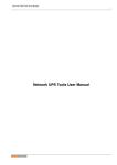
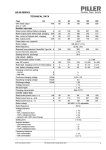
The third configuration is where a single computer controls multiple UPSes. In this case, there are several
instances of apcupsd on the same computer, each controlling a different UPS. One instance of apcupsd
will run in standalone mode, and the other instance will normally run in network mode. This type of
configuration may be appropriate for large server farms that use one dedicated machine for monitoring
and diagnostics
Here is a diagram that summarizes the possibilities:
Configuration types
If you decide to set up one of these more complex configurations, see the dedicated section on that
particular configuration.
USB Configuration
Apcupsd supports USB connections on all major operating systems: Linux, FreeBSD, OpenBSD, NetBSD,
Windows, Solaris, and Mac OS X Darwin. If you plan to use a USB connection, please read the
appropriate subsection in its entirety. You can skip this section if your UPS has a serial (RS232-C) or
Ethernet interface or if you are not running one of the platforms listed above.
Linux USB Configuration
Known Linux USB Issues
Problem
Linux 2.4 series kernels older than 2.4.22 (RH 9, RHEL 3) do not bind the USB device to the proper
driver. This is evidenced by /proc/bus/usb/devices listing the UPS correctly but it will have
"driver=(none)" instead of "driver=(hid)". This affects RHEL3, among others.
Workaround
Upgrade linux kernel to 2.4.22 or higher. Alternately, you apply the linux-2.4.20-killpower.patch and
linux-2.4.20-USB-reject.patch patches to your kernel and rebuild it. These patches can be found in
the examples/ directory in the apcupsd source distribution.
Problem
Mandrake 10.0 and 10.1 systems with high security mode enabled (running kernel-secure kernel) use
static device nodes but still assign USB minor numbers dynamically. This is evidenced by hiddev0:
USB HID v1.10 Device [...] instead of hiddev96: ... in dmesg log.
Workaround
Boot standard kernel instead of kernel-secure or disable CONFIG_USB_DYNAMIC_MINORS and
rebuild kernel-secure.
Problem
USB driver linux-usb.c fails to compile, reporting errors about HID_MAX_USAGES undefined. This
is due to a defect in the linux kernel hiddev.h header file on 2.6.5 and higher kernels.
Workaround
Upgrade to apcupsd-3.10.14 or higher. These versions contain a workaround for the defect.
Problem
On some systems such as Slackware 10.0, no USB devices will show up (see the next section).
Workaround
Add the following to rc.local
mount -t usbdevfs none /proc/bus/usb
Problem
2.6 kernels use udev and some distributions to not configure it to automatically create
/dev/usb/hiddev?? as they should, causing apcupsd to fail to locate the UPS.
Workaround
Edit the file /etc/udev/rules.d/50-udev.rules, and add the following:
KERNEL="hiddev*", NAME="usb/hiddev%n"
More details are provided in the following section ...
Verifying Device Detection and Driver
To make sure that your USB subsystem can see the UPS, just do this from a shell prompt:
cat /proc/bus/usb/devices
This information is updated by the kernel whenever a device is plugged in or unplugged, irrespective of
whether apcupsd is running or not. It contains details on all the USB devices in your system including
hubs (internal and external), input devices, and UPSes.
You should get some output back that includes something like this, featuring a BackUPS RS 1000:
T:
D:
P:
S:
S:
S:
C:*
I:
Bus=02 Lev=01 Prnt=01 Port=00 Cnt=01 Dev#= 3 Spd=1.5 MxCh= 0
Ver= 1.10 Cls=00(>ifc ) Sub=00 Prot=00 MxPS= 8 #Cfgs= 1
Vendor=051d ProdID=0002 Rev= 1.06
Manufacturer=American Power Conversion
Product=Back-UPS RS 1000 FW:7.g3 .D USB FW:g3
SerialNumber=JB0308036505
#Ifs= 1 Cfg#= 1 Atr=a0 MxPwr= 24mA
If#= 0 Alt= 0 #EPs= 1 Cls=03(HID ) Sub=00 Prot=00 Driver=hid
The important things to check for are the S: lines describing your UPS and and the I: line showing
what driver is handling it. If on the I: line, Driver is listed as Driver=none then you do not have the
HID driver loaded or the driver did not attach to the UPS. One common cause is having a Linux kernel
older than 2.4.22 (such as a stock RedHat 9 or RHEL 3 kernel). If this is the case for your system, please
upgrade to at least kernel version 2.4.22 and try again. If you are already running a 2.4.22 or higher
kernel, please read further for instructions for other possible courses of action.
Here is another example, this time featuring a Back-UPS 350:
T:
D:
P:
S:
S:
S:
C:*
I:
E:
Bus=01 Lev=01 Prnt=01 Port=00 Cnt=01 Dev#= 2 Spd=1.5 MxCh= 0
Ver= 1.10 Cls=00(>ifc ) Sub=00 Prot=00 MxPS= 8 #Cfgs= 1
Vendor=051d ProdID=0002 Rev= 1.00
Manufacturer=American Power Conversion
Product=Back-UPS 350 FW: 5.2.I USB FW: c1
SerialNumber=BB0115017954
#Ifs= 1 Cfg#= 1 Atr=a0 MxPwr= 30mA
If#= 0 Alt= 0 #EPs= 1 Cls=03(HID ) Sub=00 Prot=00 Driver=hid
Ad=81(I) Atr=03(Int.) MxPS=
8 Ivl= 10ms
In general, if you see your UPS model in the S: field, which means Manufacturer=, Product=, and
SerialNumber=, and you see Driver=hid in the I: field, you know the UPS has been recognized
and is bound to the correct driver.
If your UPS doesn't appear in the list at all, check the obvious things: The UPS must be powered on, and
a cable must be properly seated in both the data port of the UPS and one of your machine's USB ports.
Many UPSes have phone ports to provide surge protection for phones or modems -- make sure you
haven't plugged your USB cable into one of those rather than the data port (which will usually be near the
top edge of the case.)
Also, ensure that the correct drivers are loaded. Under Linux-2.4.x, you can check this out easily by
examining the /proc/bus/usb/drivers file. Here's how you can do that:
cat /proc/bus/usb/drivers
...and you should get:
usbdevfs
hub
96-111: hiddev
hid
On Linux-2.6.x, make sure the sysfs filesystem is mounted on /sys and do:
ls -l /sys/bus/usb/drivers/
...where you should get:
total 0
drwxr-xr-x
drwxr-xr-x
drwxr-xr-x
drwxr-xr-x
drwxr-xr-x
2
2
2
2
2
root
root
root
root
root
root
root
root
root
root
0
0
0
0
0
May
May
May
May
May
1
1
1
1
1
18:55
18:55
18:55
18:55
18:55
hid
hiddev
hub
usb
usbfs
...or perhaps something like:
total 0
drwxr-xr-x
drwxr-xr-x
drwxr-xr-x
drwxr-xr-x
drwxr-xr-x
2
2
2
2
2
root
root
root
root
root
root
root
root
root
root
0
0
0
0
0
Jan
Jan
Jan
Jan
Jan
6
6
6
6
6
15:27
15:28
15:28
15:27
15:28
hiddev
hub
usb
usbfs
usbhid
If your 2.6.x system does not have the /sys/bus/usb directory, either you do not have sysfs mounted on
/sys or the USB module(s) have not been loaded. (Check /proc/mounts to make sure sysfs is mounted.)
A USB UPS needs all of these drivers -- the USB device filesystem, the USB hub, the Human Interface
Device subsystem driver, and the Human Interface Device driver. If you are compiling your own kernel,
you want to enable
CONFIG_USB
CONFIG_USB_HID
CONFIG_USB_HIDDEV
CONFIG_USB_DEVICEFS
...as well as at least one USB Host Controller Driver...
CONFIG_USB_UHCI_HCD
CONFIG_USB_OHCI_HCD
CONFIG_USB_UHCI
CONFIG_USB_OHCI
(linux-2.6.x)
(linux-2.6.x)
(linux-2.4.x)
(linux-2.4.x)
Device Nodes
Apcupsd accesses USB UPSes via the hiddev device nodes. Typically these are located in
/dev/hiddevN, /dev/usb/hiddevN or /dev/usb/hiddev/hiddevN (where N is a digit 0 thru 9).
Some distributions (some Debian releases, possibly others) do not provides these device nodes for you,
so you will have to make them yourself. Check /dev, /dev/usb, and /dev/usb/hiddev and if you
cannot find the hiddevN nodes, run (as root) the examples/make-hiddev script from the apcupsd
source distribution.
Modern Linux distributions using the 2.6 kernel create device nodes dynamically on the fly as they are
needed. It is basically a hotplug system, giving a lot more power to the user to determine what happens
when a device is probed or opened. It is also a lot more complicated.
Some early 2.6 distributions (Fedora Core 3, for one) do not include hiddev rules in their default udev rule
set. The bottom line for apcupsd on such a system is that if the hiddevN is not created when you plug in
your UPS, apcupsd will terminate with an error. The solution to the problem is to add a rule to the udev
rules file. On Fedora FC3, this file is found in /etc/udev/rules.d/50-udev.rules. Start by adding
the following line:
BUS="usb", SYSFS{idVendor}="051d", NAME="usb/hiddev%n"
Note that this rule uses obsolete udev syntax and is specific to FC3 and other distributions of similar
vintage.
Then either reboot your system, or unplug and replug your UPS and then restart apcupsd. At that point a
/dev/usb/hiddevN node should appear and apcupsd should work fine.
If you have several UPSes or you just want to give your UPS a fixed name, you can use rules like the
following:
KERNEL=="hiddev*", SYSFS{serial}=="JB0319033692", SYMLINK="ups0"
KERNEL=="hiddev*", SYSFS{serial}=="JB0320004845", SYMLINK="ups1"
Note that this rule uses udev syntax that is appropriate only for distros such as RHEL4 and FC4 and
others of a similar vintage.
More recent distros such as FC15 should use something like this:
KERNEL=="hiddev*", ATTRS{manufacturer}=="American Power Conversion", ATTRS{serial}=="BB0100009999
", OWNER="root", SYMLINK+="ups0"
Replace the serial number in quotes with the one that corresponds to your UPS. Then whenever you plug
in your UPS a symlink called ups0, ups1, etc. will be created pointing to the correct hiddev node. This
technique is highly recommended if you have more than one UPS connected to the same server since
rearranging your USB cables or even upgrading the kernel can affect the order in which devices are
detected and thus change which hiddev node corresponds to which UPS. If you use the
symlink-by-serial-number approach the link will always point to the correct device node.
You can use...
udevinfo -a -p /sys/class/usb/hiddev0/
...to get more information on the fields that can be matched besides serial number.
To find the available attributes to match (note that the serial is NOT always the UPS serial on the box or in
the USB connect message in /var/log/messages), use:
udevadm info --attribute-walk --name=/dev/usb/hiddev0
An additional device-node-related problem is the use of dynamic minors. Some distributions, such as
Mandrake 10, ship with a kernel having CONFIG_USB_DYNAMIC_MINORS turned on. This is not ideal for
running with apcupsd, and the easiest solution is to turn CONFIG_USB_DYNAMIC_MINORS off and rebuild
your kernel, or find a pre-built kernel with it off. For a kernel with CONFIG_USB_DYNAMIC_MINORS turned
on to work with apcupsd, you must enable devfs. The following will tell you if devfs is enabled:
$ ps ax | grep devs
...which should give something like the following:
533 ?
S
0:00 devfsd /dev
What complicates the situation much more on Mandrake kernels is their security level since
CONFIG_DYNAMIC_USB_MINORS is turned on, but on higher security levels devfs is turned off. The net
result, is that in those situations hiddev is completely unusable so apcupsd will not work. So, in these
cases, the choices are:
1. Reduce the security level setting of the system (not sure if this is possible after the initial install).
2. Custom build a high security kernel with devfs enabled and make sure devfs is mounted and devfsd
is running.
3. Custom build a high security kernel with dynamic minors disabled
4. Use udev
Miscellaneous
If all these things check out and you still can't see the UPS, something is more seriously wrong than this
manual can cover -- find expert help. If you are unable to list USB devices or drivers, you kernel may not
be USB-capable and that needs to be fixed.
BSD USB Configuration
Known BSD USB Issues
Problem
FreeBSD lockups: Some users have experienced lockups (apcupsd stops responding) on FreeBSD
systems.
Solution
Recent versions of Apcupsd have addressed this issue. Please upgrade to apcupsd-3.10.18 or
higher.
Problem
FreeBSD kernel panics if USB cable is unplugged while apcupsd is running.
Solution
This is a kernel bug and is most easily worked around by not hot- unplugging the UPS while apcupsd
is running. This issue may be fixed in recent FreeBSD kernels.
Platforms and Versions
The *BSD USB driver supports FreeBSD, OpenBSD and NetBSD. (Thanks go to the *BSD developers
who kept a nearly identical interface across all three platforms.)
Kernel Configuration
Users of OpenBSD, NetBSD, and some versions of FreeBSD will need to rebuild the kernel in order to
enable the ugen driver and disable the uhid driver. uhid is not sufficient for apcupsd at this time and we
need to prevent it from grabbing the UPS device. You should make the following changes to your kernel
config file:
FreeBSD (v5.4 and below, v6.0)
(you will not lose use of USB keyboard and mouse)
Disable: uhid
Enable: ugen
FreeBSD (v5.5, v6.1 and above)
(you will not lose use of USB keyboard and mouse)
Disable: (nothing)
Enable: ugen
This is the default configuration for a GENERIC kernel on many platforms so you most likely will not
need to recompile.
NetBSD (v3.x and below)
(you will lose use of USB keyboard and mouse)
Disable: uhidev, ums, wsmouse, ukbd, wskbd, uhid
Enable: ugen
NetBSD (v4.0 and above)
You can use apcupsd on single USB port without disabling the USB keyboard and mouse on other
ports, though all other devices will be disabled on the port you pick for your UPS.
First, decide which hub and port you wish to use. You can find out the hub and port numbers for any
particular physical connector by plugging a USB device into it and looking at the messages printed by
the kernel; you should messages something like this:
uxx0 at uhub0 port 1
uxx0: <some device name>
To use your APC UPS on this port, configure the kernel to prefer attachment of the ugen driver over
other drivers on this hub and port only, by adding a line like this to your kernel config file:
ugen*
at uhub0 port 1 flags 1
(The "flags 1" forces the ugen to attach instead of anything else detected there.)
Configure and build that kernel as per the references below, and your UPS will now attach as a ugen
device when plugged into that port.
Don't forget to 'cd /dev' and './MAKEDEV ugen1' (and 2 and so on) if you have more than one
generic usb device on your system.
OpenBSD
(you will lose use of USB keyboard and mouse):
Disable: uhidev, ums, wsmouse, ukbd, wskbd, uhid
Enable: ugen
For detailed information on rebuilding your kernel, consult these references:
FreeBSD
http://www.freebsd.org/doc/en_US.ISO8859-1/books/handbook/kernelconfig.html
NetBSD
http://www.netbsd.org/guide/en/chap-kernel.html
OpenBSD
http://www.openbsd.org/faq/faq5.html#Building
Verifying Device Detection and Driver
After building a properly configured kernel, reboot into that kernel and plug in your UPS USB cable. You
should see a dmesg log message like the following:
ugen0: American Power Conversion Back-UPS RS 1500 FW:8.g6 .D USB FW:g6, rev 1.10/1.06, addr 2
Note that the ugen driver is called out. If you see uhid instead, it probably means you did not properly
disable the uhid driver when you compiled your kernel or perhaps you're not running the new kernel.
You can also check with 'usbdevs -d' to get a list of USB devices recognized by the system as well as
the drivers they are associated with. For example:
# usbdevs -d
addr 1: UHCI root hub, VIA
uhub0
addr 2: Back-UPS RS 1500 FW:8.g6 .D USB FW:g6, American Power Conversion
ugen0
Device Nodes
Apcupsd communicates with the UPS through the USB generic device, ugen. You may or may not need
to manually make ugen device nodes in /dev, depending on what OS you are using.
FreeBSD
No manual intervention needed. FreeBSD automatically creates the ugen nodes on demand.
NetBSD
By default, NetBSD only creates nodes for the first ugen device, ugen0. Check usbdevs -d to see
which device your UPS was bound to and then create the appropriate node by running 'cd /dev ;
./MAKEDEV ugenN', where ugenN is the ugen device name shown by usbdevs. It is probably a
good idea to create several sets of ugen nodes in case you add more USB devices.
OpenBSD
Similar to NetBSD, OpenBSD creates nodes for ugen0 and ugen1. Check usbdevs -d to see
which device your UPS was bound to and then create the appropriate node by running 'cd /dev ;
./MAKEDEV ugenN', where ugenN is the ugen device name shown by usbdevs. It is probably a
good idea to create several sets of ugen nodes in case you add more USB devices.
Windows USB Configuration
Platforms and Versions
Apcupsd supports USB UPSes on Windows XP and newer, including 64 bit systems.
USB Driver Installation
USB connected UPSes on Windows require a special driver. In most cases, this driver is automatically
installed when you install Apcupsd. However in some cases you may need to install the driver manually.
For detailed instructions, please see the install.txt file located in the driver folder of your Apcupsd
install.
Verifying Device Detection and Driver
After installing Apcupsd (and the Apcupsd USB driver, if necessary), plug in your UPS USB cable and
open the Windows Device Manager. You should see a American Power Conversion USB UPS
(Apcupsd) listed under the Batteries section. If a device of that name does not appear, check that
your UPS is powered on and that the USB cable is connected at both ends. Reinstall the driver as
directed above if needed.
Solaris USB Configuration
Platforms and Versions
Apcupsd supports USB UPSes on Solaris 10 and higher. Both x86 and SPARC platforms are supported.
Building Apcupsd with USB
Some specific packages are necessary when building Apcupsd with USB support on Solaris. You must
install the SUNWlibusb and SUNWlibusbugen packages BEFORE attempting to build Apcupsd. These
packages can be found on the Solaris installation CDROMs and should be installed with the pkgadd
utility.
You also should build using the gcc compiler and ccs make, not Sun's compiler. The appropriate make
utility can be found in /usr/ccs/bin. gcc can be installed from packages included on the Solaris
installation CDROMs.
Configure and build Apcupsd normally, as described in Building and Installing Apcupsd. Be sure to include
the --enable-usb flag to configure.
After building, install Apcupsd as root using 'make install', then perform a reconfigure boot ('reboot
-- -r'). During installation, Apcupsd will automatically configure your USB subsystem to attach APC USB
devices to the ugen driver. This is a critical step and must be completed by a reconfigure boot. Note that
the USB config changes will be reversed if you remove Apcupsd using 'make uninstall'.
Verifying Device Detection and Driver
After installing Apcupsd as described above and performing a reconfigure boot, plug in your UPS USB
cable. You should see a series of dmesg log messages similar to the following:
Dec
Dec
Dec
Dec
5
5
5
5
17:50:50
17:50:50
17:50:50
17:50:50
sunblade
sunblade
sunblade
sunblade
usba: [ID 912658 kern.info] USB 1.10 device (usb51d,2) operating at low speed (USB 1.x) on USB 1.10 root hub: input@4, ugen0 at bus address 3
usba: [ID 349649 kern.info]
American Power Conversion Smart-UPS 1000 FW:600.1.D USB FW:1.2 AS0127232356
genunix: [ID 936769 kern.info] ugen0 is /pci@1f,0/usb@c,3/input@4
genunix: [ID 408114 kern.info] /pci@1f,0/usb@c,3/input@4 (ugen0) online
Note that the ugen driver is called out. If you do not see any dmesg entries related to your UPS, ensure
that it is turned on and that the USB cable is connected at both ends. Also verify that you installed
Apcupsd as root using the 'make install' command and that you performed a reconfigure boot
afterward.
Device Nodes
Apcupsd communicates with the UPS through the USB generic device, ugen. The reconfigure boot
performed after Apcupsd installation will ensure the correct device nodes are created. Once your UPS has
been recognized in dmesg as shown above, you can check /dev/usb to see if the device nodes have
appeared:
[user@sunblade /]$ ls /dev/usb/51d.2/*
cntrl0
cntrl0stat devstat
if0in1
if0in1stat
(51d.2 is the vendor/product id for APC UPSes.)
Mac OS X (Darwin) USB Configuration
Platforms and Versions
Apcupsd supports USB UPSes on Mac OS X (Darwin) 10.4.x and higher. Both Intel and PowerPC
platforms are supported.
Building Apcupsd with USB
Some specific packages are necessary when building Apcupsd with USB support on Darwin. You must
install libusb-0.1.12 which can be obtained from MacPorts (http://www.macports.org) (formerly
DarwinPorts) or Fink (http://fink.sourceforge.net) or downloaded and built by hand (http://www.libusb.org).
You must not use libusb-1.x or higher (apcupsd does not support the new 1.0 APIs) nor any version
earlier than 0.1.12 (earlier versions have a bug that apcupsd triggers). Generally that means you must use
exactly 0.1.12. Note that Apcupsd is sensitive to the install location of libusb, so beware if you change it
from the default.
Apcupsd should be built using gcc, preferably from the XCode development tools. Currently the
maintainer is using gcc-4.0.1 from XCode 2.4. Other versions of gcc from other sources may also work.
Configure and build Apcupsd normally, as described in Building and Installing Apcupsd. Be sure to include
the --enable-usb flag to configure.
After building, install Apcupsd as root using 'make install' and then reboot. During installation,
Apcupsd will automatically install a simple dummy kext driver designed to prevent Apple's monitoring
software from taking over the UPS. It is necessary to reboot in order to activate the kext. Note that this
kext will be automatically removed if you uninstall Apcupsd using 'make uninstall', allowing Apple's
monitoring tool to once again access the UPS.
Verifying Device Detection and Driver
After installing Apcupsd as described above and rebooting, plug in your UPS USB cable. You should
notice that Darwin does NOT display the battery monitor tool in the menu bar. You can also check Apple
Menu -> About This Mac -> More Info... -> USB to ensure that your UPS appears in the list of USB
devices.
Building and Installing apcupsd
In general it is recommended to obtain a prebuilt binary package for your platform. Given how apcupsd
must integrate into the shutdown mechanism of the operating system and the rate at which such
mechanisms are changed by vendors, the platform ports in the apcupsd tree may become out of date. In
some cases, binary packages are provided by the apcupsd team (RedHat, Mandriva, SuSE, Windows,
Mac OS X). For other platforms it is recommended to check your vendor's package repository and third
party repositories for recent binary packages before resorting to building apcupsd from scratch. Note that
some vendors continue to distribute ancient versions of apcupsd with known defects. These packages
should not be used.
Installation from Binary Packages
RPMS
For systems based on RPM packages, such as Red Hat and SuSE, apcupsd is available in binary RPM
format. This is the simplest way to install. If you have no previous version of apcupsd on your machine
and are creating a standalone configuration, simply install the RPM with a normal 'rpm -ihv' command.
You're done, and can now skip the rest of this chapter and go straight to tweaking your run-time
configuration file. (see After Installation)
If you have a previous installation, you can upgrade with a normal 'rpm -Uhv', but this may not upgrade
the halt script. It may be better to do the upgrade as a remove 'rpm -e' followed by a fresh install 'rpm
-ihv'.
After installation of the binary RPM, please verify carefully that /etc/rc.d/init.d/halt was properly updated
and contains new script lines flagged with ***APCUPSD***.
Since there is no standard location for cgi-bin, the rpm will place the binary CGI programs in the directory
/etc/apcupsd/cgi. To actually use them, you must copy or move them to your actual cgi-bin directory,
which on many systems is located in /home/httpd/cgi-bin.
Microsoft Windows
The Windows version of apcupsd is distributed as a simple double-click installer. Installation is very simple
and straight-forward: Simply double-click the installer executable and follow the instructions. See The
Windows Version of apcupsd for further details.
Installation from Source
Installation from source might have to be be done different ways depending on what system you are
running. The basic procedure involves getting a source distribution, running the configuration, rebuilding,
and installing.
For building the system, we suggest that you run the configure and make processes as your normal UNIX
user ID. The 'make install' must be run as root. But if your normal ID has an environment setup for
using the C compiler, it's simpler to do that than to set up root to have the correct environment.
apcupsd requires gcc and g++ compilers as well as GNU make. Other compilers or BSD make will not
work. GNU make is sometimes installed as gmake. The configure script will check for this and will inform
you of what command to use to invoke GNU make.
The basic installation from a tar source file is rather simple:
1. Unpack the source code from its tar archive.
2. Go into the directory containing the source code.
3. Run './configure' (with appropriate options as described below)
4. 'make' or 'gmake'' as instructed by configure
5. 'su' (i.e. become root)
6. Stop any running instance of apcupsd.
'system-dependent-path/apcupsd stop'
The
command
to
do
this
will
look
like
7. uninstall any old apcupsd This is important since the default install locations may have changed.
8. 'make install' or 'gmake install'
9. edit your /etc/apcupsd/apcupsd.conf file if necessary
10. ensure that your halt script is properly updated
11. Start the new apcupsd with: 'system-dependent-path/apcupsd start'
If all goes well, the './configure' will correctly determine which operating system you are running and
configure the source code appropriately. configure currently recognizes the systems listed below in the
Operating System Specifics section of this chapter and adapts the configuration appropriately. Check that
the configuration report printed at the end of the configure process corresponds to your choice of
directories, options, and that it has correctly detected your operating system. If not, redo the configure
with the appropriate options until your configuration is correct.
Please note that a number of the configure options preset apcupsd.conf directive values in an attempt
to automatically adapt apcupsd as best possible to your system. You can change the values in
apcupsd.conf at a later time without redoing the configuration process by simply editing the apcupsd.conf
file.
Other configuration options can be used to set up the installation of HTML documentation and optional
modules, notably the CGI interface that enables the UPS state to be queried via the Web. You will find a
complete reference later in this chapter.
In general, you will probably want to supply a more elaborate configure statement to ensure that the
modules you want are built and that everything is placed into the correct directories.
On Red Hat, a fairly typical configuration command would look like the following:
CFLAGS="-g -O2" LDFLAGS="-g" ./configure \
--enable-usb \
--with-upstype=usb \
--with-upscable=usb \
--prefix=/usr \
--sbindir=/sbin \
--with-cgi-bin=/var/www/cgi-bin \
--enable-cgi \
--with-log-dir=/etc/apcupsd
By default, 'make install' will install the executable files in /sbin, the manuals in /usr/man, and the
configuration and script files in /etc/apcupsd. In addition, if your system is recognized, certain files such as
the startup script and the system halt script will be placed in appropriate system directories (usually
subdirectories of /etc/rc.d).
Verifying a Source Installation
There are a number of things that you can do to check if the installation (make install) went well. The fist is
to check where the system has installed apcupsd using 'which' and 'whereis'. On my Red Hat system,
you should get the following (lines preceded with a $ indicate what you type):
$ which apcupsd
/sbin/apcupsd
$ whereis apcupsd
apcupsd: /sbin/apcupsd /etc/apcupsd /etc/apcupsd.conf
/etc/apcupsd.status /usr/man/man8/apcupsd.8.gz
/usr/man/man8/apcupsd.8
If you find an apcupsd in /usr/sbin, /usr/local/sbin, /usr/lib, or another such directory, it is probably a piece
of an old version of apcupsd that you can delete. If you are in doubt, delete it, then rerun the 'make
install' to ensure that you haven't deleted anything needed by the new apcupsd. Please note that the
files specified above assume the default installation locations.
As a final check that the 'make install' went well, you should check your halt script (in /etc/rc.d on
SUSE systems, and in /etc/rc.d/init.d on Red Hat systems) to see that the appropriate lines have been
inserted in the correct place. Modification of the halt script is important so that at the end of the shutdown
procedure, apcupsd will be called again to command the UPS to turn off the power. This should only be
done in a power failure situation as indicated by the presence of the /etc/powerfail file, and is necessary if
you want your machine to automatically be restarted when the power returns. On a Red Hat system, the
lines containing the # ***apcupsd*** should be inserted just before the final halt command:
# Remount read only anything that's left mounted.
#echo "Remounting remaining filesystems (if any) readonly"
mount | awk '/ext2/ { print $3 }' | while read line; do
mount -n -o ro,remount $line
done
# See if this is a powerfail situation.
if [ -f /etc/apcupsd/powerfail ]; then
echo
echo "APCUPSD will now power off the UPS"
echo
/etc/apcupsd/apccontrol killpower
echo
echo "Please ensure that the UPS has powered off before rebooting"
echo "Otherwise, the UPS may cut the power during the reboot!!!"
echo
fi
#
#
#
#
#
#
#
#
#
#
#
***apcupsd***
***apcupsd***
***apcupsd***
***apcupsd***
***apcupsd***
***apcupsd***
***apcupsd***
***apcupsd***
***apcupsd***
***apcupsd***
***apcupsd***
# Now halt or reboot.
echo "$message"
if [ -f /fastboot ]; then
echo "On the next boot fsck will be skipped."
elif [ -f /forcefsck ]; then
echo "On the next boot fsck will be forced."
fi
The purpose of modifying the system halt files is so that apcupsd will be recalled after the system is in a
stable state. At that point, apcupsd will instruct the UPS to shut off the power. This is necessary if you
wish your system to automatically reboot when the mains power is restored. If you prefer to manually
reboot your system, you can skip this final system dependent installation step by specifying the
disable-install-distdir option on the './configure' command (see below for more details).
The above pertains to Red Hat systems only. There are significant differences in the procedures on each
system, as well as the location of the halt script. Also, the information that is inserted in your halt script
varies from system to system. Other systems such as Solaris require you the make the changes manually,
which has the advantage that you won't have any unpleasant surprises in your halt script should things go
wrong. Please consult the specific system dependent README files for more details.
Please note that if you install from RPMs for a slave machine, you will need to remove the changes that
the RPM install script made (similar to what is noted above) to the halt script. This is because on a slave
machine there is no connection to the UPS, so there is no need to attempt to power off the UPS. That will
be done by the master.
Configure Options
All the available configure options can be printed by entering:
./configure --help
When specifying options for './configure', if in doubt, don't put anything, since normally the
configuration process will determine the proper settings for your system. The advantage of these options
is that it permits you to customize your version of apcupsd. If you save the './configure' command that
you use to create apcupsd, you can quickly reset the same customization in the next version of apcupsd
by simply re-using the same command.
The following command line options are available for configure to customize your installation.
--prefix=path
This defines the directory for the non-executable
files such as the manuals. The default is /usr.
--sbindir=path
This defines the directory for the executable files
such as apcupsd. The default is /sbin. You may
be tempted to place the executable files in
/usr/sbin or /usr/local/sbin. Please use caution
here as these directories may be unmounted
during a shutdown and thus may prevent the
halt script from calling apcupsd to turn off the
UPS power. Though your data will be protected, in
this case, your system will probably not be
automatically rebooted when the power returns
--enable-cgi
This enables the building of the CGI programs
that permit Web browser access to apcupsd data.
This option is not necessary for the proper
execution of apcupsd.
--with-cgi-bin=path
The with-cgi-bin configuration option allows you to
define the directory where the CGI programs will
be installed. The default is /etc/apcupsd, which is
probably not what you want.
--enable-apcsmart
Turns on generation of the APC Smart driver
(default).
--enable-dumb
Turns on generation of the dumb signalling driver
code (default).
--enable-usb
Turns on generation of the USB driver code. By
default this is disabled.
--enable-net
Turns on generation of the NIS network driver for
slaves. For each slave, this is the only driver
needed. This driver works by reading the
information from the the configured master using
the NIS (Network Information Services) interface.
--enable-snmp
--enable-net-snmp
--enable-pcnet
--enable-test
--enable-gapcmon
--enable-apcagent
--with-libwrap=path, --with-libwrap
--with-nologin=path
--with-pid-dir=path
--with-log-dir=path
--with-lock-dir=path
--with-pwrfail-dir=path
Turns on generation of the SNMP driver. This
driver accesses the UPS over the network using
SNMP. This is compatible only with UPSes
equipped with an SNMP or Web/SNMP
management card. By default this is enabled.
Turns on generation of the obsolete NET-SNMP
driver. This driver was the precursor to the current
snmp driver and is now obsolete. It is available as
a fallback if the new driver cannot be used for
some reason. By default this is disabled.
Turns on generation of the PCNET (PowerChute
Network Shutdown) driver. This driver accesses
the UPS over the network using APC's custom
protocol. This driver can be used as an alternative
to SNMP for UPSes equipped with a modern
Web/SNMP management card.
This turns on a test driver that is used only for
debugging. By default it is disabled.
This option enables building the GTK GUI
front-end for apcupsd. Building this package
requires numerous GNOME libraries. The default
is disabled.
This option enables building the apcagent
menubar application on Mac OS X platforms. The
default is disabled.
This option when enabled causes apcupsd to be
built with the TCP WRAPPER library for enhanced
security. In most cases, the path is optional since
configure will determine where the libraries are on
most systems.
This option allows you to specify where apcupsd
will create the nologin file when logins are
prohibited. The default is /etc
This option allows you to specify where apcupsd
will create the process id (PID) file to prevent
multiple copies from running. The default is
system dependent but usually /var/run.
This option allows you to specify where apcupsd
will create the EVENTS and STATUS log files.
The default is /etc/apcupsd. This option simply
sets the default of the appropriate path in the
apcupsd.conf file, which can be changed at any
later time.
This option allows you to specify where apcupsd
will create the serial port lock file. The default is
system-dependent but usually /var/lock. This
option simply sets the appropriate path in the
apcupsd.conf file, which can be changed at any
later time.
This option allows you to specify where apcupsd
will create the powerfail file when a power failure
occurs. The default is system dependent but
usually /etc.
--with-serial-dev=device-name
--with-nis-port=port
--with-nisip=ip-address
--with-net-port=port
--with-upstype=type
--with-upscable=cable
--disable-install-distdir
This option allows you to specify where apcupsd
will look for the serial device that talks to the UPS.
The default is system dependent, but often
/dev/ttyS0. This option simply sets the appropriate
device name in the apcupsd.conf file, which can
be changed at any later time.
This option allows you to specify what port
apcupsd will use for the Network Information
Server (the CGI programs). The default is system
dependent but usually 3551 because that port has
been officially assigned to apcupsd by the IANA.
This option simply sets the appropriate port in the
apcupsd.conf file, which can be changed at any
later time.
This option allows you to specify the value that will
be placed on then NISIP directive in the
configuration file. The default is 0.0.0.0. No
checking is done on the value entered, so you
must ensure that it is a valid IP address.
This option allows you to specify what port
apcupsd will use for Master and Slave
communications. The default is system dependent
but usually 6666. This option simply sets the
appropriate port in the apcupsd.conf file, which
can be changed at any later time.
This option allows you to specify the type of UPS
that will be connected to your computer. The
default is: smartups. This option simply sets the
appropriate UPS type in the apcupsd.conf file,
which can be changed at any later time.
This option allows you to specify what cable you
are using to connect to the UPS. The default is:
smart. This option simply sets the appropriate
UPS cable in the apcupsd.conf file, which can be
changed at any later time.
This option modifies the apcupsd Makefiles
disable installation of the distribution (platform)
directory. Generally, this used to do a full
installation of apcupsd except the final
modification of the operating system files
(normally /etc/rc.d/halt, etc.). This is useful if your
operating system is not directly supported by
apcupsd or if you want to run two copies of
apcupsd on the same system. This option can
also be used by those of you who prefer to
manually reboot your system after a power failure
or who do not want to modify your system halt
files.
Recommended Options for most Systems
For most systems, we recommend the following options:
./configure --prefix=/usr --sbindir=/sbin --enable-usb
and you can optionally build and install the CGI programs as follows:
./configure --prefix=/usr --sbindir=/sbin --enable-usb \
--enable-cgi --with-cgi-bin=/home/httpd/cgi-bin
Compilers and Options
Some systems require unusual options for compilation or linking that the './configure' script does not
know about. You can specify initial values for variables by setting them in the environment. Using a
Bourne-compatible shell, you can do that on the command line like this:
CFLAGS="-O2 -Wall" LDFLAGS= ./configure
Or on systems that have the env program, you can do it like this:
env CPPFLAGS=-I/usr/local/include LDFLAGS=-s ./configure
Or for example on the Sun Solaris system, you can use:
setenv CFLAGS -O2
setenv LDFLAGS -O
./configure
You can get a listing of all available options by doing:
./configure --help
or simply see the previous section of this manual.
Operating System Specifics
With the exception of Linux SUSE and Linux Red Hat systems used by the developers, we rely on users
to help create installation scripts and instructions as well as to test that apcupsd runs correctly on their
system. As you can imagine, most of these people are system administrators rather than developers so
they are very busy and don't always have time to test the latest releases. With that in mind, we believe
that you will find that a lot of very valuable work has been already done to make your installation much
easier (and probably totally automatic).
Below, you will find a list of operating systems for which we have received installation files:
• Debian (see Debian)
• FreeBSD (see FreeBSD)
• HPUX (see HPUX)
• NetBSD (see NetBSD)
• Mac OS X Darwin (see Mac OS X Darwin)
• OpenBSD (see OpenBSD)
• Red Hat (see Red Hat Systems)
• Slackware (see Slackware)
• SUSE (see SUSE)
• Solaris (see Sun Solaris)
• unknown (see Unknown System)
• Win32 (see Windows Systems)
Debian
This port is complete and is being used by several users. Since Debian build and install procedures are
somewhat particular, we have put the extra Debian information into the following two subdirectories:
platforms/debian/examples and platforms/debian/packageinfo
You can also find the official Debian packages on the Debian site at:
• https://packages.debian.org/stable/apcupsd
• https://packages.debian.org/testing/apcupsd
• https://packages.debian.org/unstable/apcupsd
FreeBSD
This port is complete and is being used by several users.
You will need to install and use GNU make (aka gmake) instead of the BSD make supplied with the
system.
On the FreeBSD OS, there is no known way for a user program to get control when all the disks are
synced. This is needed for apcupsd to be able to issue the killpower command to the UPS so that the
UPS shuts off the power. To accomplish the same thing on FreeBSD systems, make sure you have a
SmartUPS and that your UPS shutdown grace period is set sufficiently long so that you system will power
down (usually 2 minutes), the use the --kill-on-powerfail option on the apcupsd command line.
HPUX
Status of this port is unknown.
NetBSD
You will need to install and use GNU make (aka gmake) instead of the BSD make supplied with the
system.
Mac OS X Darwin
On OS X (Darwin), apcupsd can be built with configure defaults. The USB driver can be enabled, as
per the directions on Mac OS X (Darwin) USB Configuration Apcupsd may be usable on OS X with a
smart serial device, but certainly does work as a NIS client or using a USB interface.
The startup information will be installed in /Library/StartupItems/apcupsd which is part of
darwin's SystemStartup.
OpenBSD
You will need to install and use GNU make (aka gmake) instead of the BSD make supplied with the
system.
Ensure that you read the distributions/openbsd/README file before running apcupsd. There are some
critical differences in how the OpenBSD implementation operates when the UPS batteries are exhausted.
Failure to take this into account may result in the system not being fully halted when power is lost.
Red Hat Systems
Red Hat systems are fully supported, and by following the standard installation instructions given above,
you should experience few or no problems.
Slackware
Slackware systems are fully supported, and by following the standard installation instructions given above,
you should experience few or no problems.
SUSE
SUSE systems are fully supported, and by following the standard installation instructions given above, you
should experience few or no problems.
Sun Solaris
Please read this before attempting to compile or install the beta software. It contains important information
that will make your efforts easier.
Before running './configure', please be sure that you do not have /usr/ucb on your path. This may
cause the configure to choose the wrong shutdown program. If configure detects that /usr/usb is on
your path, it will print a warning message. Please follow the advice to avoid shutdown problems.
Your normal UNIX user ID must own the source tree directories, and you must have the normal
development tools in your path. This includes make, the compiler, the M4 preprocessor, the linker, and ar
or ranlib. If the user you are logged in as can compile and link a C program from a source file, then you
have all the required tools available.
You will want to install the executables in a directory that remains mounted during the shutdown. Solaris
will unmount almost everything except the root directories. Since the ability to power the UPS off requires
access to the executable programs, they need to be in a directory that will never be unmounted. And since
they should also be in a directory that normal users cannot get into, /sbin is the default. However, please
be aware that if you want to follow Sun's filesystem conventions you would use the following:
./configure \
--prefix=/opt/apcupsd \
--sbindir=/etc/opt/apcupsd/sbin \
--sysconfdir=/etc/opt/apcupsd \
--with-cgi-bin=/opt/apcupsd/cgi-bin
The way to setup the /sbin directory as the executables directory is to pass configure the
--sbindir=/sbin option. No other arguments should be required, and your setup and platform should
be detected automatically by configure.
Once you have run configure, you will need to do a 'gmake'. Once the make has completed with no errors,
you must su to root to complete the install. After the su, you may not have a path to the make program
anymore. In that case, you should do the 'gmake install' step as:
gmake install
Once the install completes, you must edit the /sbin/rc0 script as detailed below, then exit from the su'ed
shell.
In order to support unattended operation and shutdown during a power failure, it's important that the UPS
remove power after the shutdown completes. This allows the unattended UPS to reboot the system when
power returns by re-powering the system. Of course, you need autoboot enabled for your system to do
this, but all Solaris systems have this by default. If you have disabled this on your system, please
re-enable it.
To get the UPS to remove power from the system at the correct time during shutdown, i.e., after the disks
have done their final sync, we need to modify a system script. This script is /sbin/rc0.
We do not have access to every version of Solaris, but we believe this file will be almost identical on every
version. Please let us know if this is not true.
At the very end of the /sbin/rc0 script, you should find lines just like the following:
# unmount file systems. /usr, /var and /var/adm are not unmounted by umountall
# because they are mounted by rcS (for single user mode) rather than
# mountall.
# If this is changed, mountall, umountall and rcS should also change.
/sbin/umountall
/sbin/umount /var/adm >/dev/null 2>\&1
/sbin/umount /var >/dev/null 2>\&1
/sbin/umount /usr >/dev/null 2>\&1
echo 'The system is down.'
We need to insert the following lines just before the last 'echo':
#see if this is a powerfail situation
if [ -f /etc/apcupsd/powerfail ]; then
echo
echo "APCUPSD will power off the UPS"
echo
/etc/apcupsd/apccontrol killpower
echo
echo "Please ensure that the UPS has powered off before rebooting"
echo "Otherwise, the UPS may cut the power during the reboot!!!"
echo
fi
We have included these lines in a file called rc0.solaris in the distributions/sun subdirectory of the source
tree. You can cut and paste them into the /sbin/rc0 file at the correct place, or yank and put them using vi
or any other editor. Note that you must be root to edit this file.
You must be absolutely sure you have them in the right place. If your /sbin/rc0 file does not look like the
lines shown above, do not modify the file. Instead, email a copy of the file to the maintainers, and we will
attempt to figure out what you should do. If you mess up this file, the system will not shut down cleanly,
and you could lose data. Don't take the chance.
You will then need to make the normal changes to the /etc/apcupsd/apcupsd.conf file. This file contains
the configuration settings for the package. It is important that you set the values to match your UPS model
and cable type, and the serial port that you have attached the UPS to. People have used both /dev/ttya
and /dev/ttyb with no problems. You should be sure that logins are disabled on the port you are going to
use, otherwise you will not be able to communicate with the UPS. If you are not sure that logins are
disabled for the port, run the 'admintool' program as root, and disable the port. The 'admintool' program is
a GUI administration program, and required that you are running CDE, OpenWindows, or another
XWindows program such as KDE.
Solaris probes the serial ports during boot, and during this process, it toggles some handshaking lines
used by dumb UPSes. As a result, particularly for simple signalling "dumb" UPSes it seems to kick it into a
mode that makes the UPS think it's either in a calibration run, or some self-test mode. Since at this point
we are really not communicating with the UPS, it's pretty hard to tell what happened. But it's easy to
prevent this, and you should. Disconnect the UPS, and boot the system. When you get to a login prompt,
log in as root. Type the following command:
eeprom com1-noprobe=true
or
eeprom com2-noprobe=true
depending on which com port your UPS is attached to. Then sync and shutdown the system normally,
reattach the UPS, and reboot. This should solve the problem. However, we have some reports that recent
versions of Solaris (7 & 8) appear to have removed this eeprom option and there seems to be no way to
suppress the serial port probing during boot.
At this point, you should have a complete installation. The daemon will load automatically at the next boot.
Watch for any error messages during boot, and check the event logs in /etc/apcupsd. If everything looks
OK, you can try testing the package by removing power from the UPS. NOTE! if you have a
voltage-signalling UPS, please run the first power tests with your computer plugged into the wall rather
than into the UPS. This is because dumb serial-port UPSes have a tendency to power off if your
configuration or cable are not correct.
As a user, your input is very helpful in solving problems with the package, and providing suggestions and
future directions for the development of the package. We are striving to provide a useful package that
works across all platforms, and welcome your feedback.
Unknown System
During the './configure', if apcupsd does not find one of the systems for which it has specific
installation programs, it will set the Operating System to unknown and will use the incomplete installation
scripts that are in platforms/unknown. You will be on your own, or you can ask the developers list
([email protected]) for installation instructions. This directory also contains a hint file
for Linux From Scratch, which could be helpful for other systems as well.
Windows Systems
Appropriate scripts (actually Windows batch files) are included with the Apcupsd Win32 installer package.
After Installation
Checking Your Configuration File
Once you have installed apcupsd, either from a binary package or by building from source, your next step
should be to inspect your /etc/apcupsd/apcupsd.conf file to make sure it is valid.
You can read the complete reference on configuration directives (Configuration Directive Reference), but
if you are setting up a normal standalone configuration you should only need to check (and possibly fix)
the first three items listed below.
Your UPSTYPE should be the UPS's protocol type: dumb, apcsmart, usb, net, pcnet, or snmp. Your
UPSCABLE should be the type of cable you are using.
DEVICE should be set to the path of the device node (usually in /dev) to use to communicate with the
UPS. This is used primarily for serial port connections. If you have a USB device, it is better not to specify
a DEVICE directive by leaving it black or commenting it out. Apcupsd will automatically search for your
device in the standard places. If you specify a DEVICE, it should be the name of the device that apcupsd
is to use to communicate with the UPS.
If the first time you execute apcupsd, you get a message to the effect that the Apcupsd USB driver is
missing, it means that you most likely forgot to put --enable-usb on your './configure' command
line.
The Configuration Examples chapter of this manual provides the essential characteristics of each main
type of configuration file. After those elements are correct, apcupsd should run, and then it is only a matter
of customization of your setup.
Arranging for Reboot on Power-Up
The final consideration for a automatic reboot after a full power down is to ensure that your computer will
automatically reboot when the power is restored.
This is not the normal behavior of most computers as shipped from the factory. Normally after the power is
cut and restored, you must explicitly press a button for the power to actually be turned on. You can test
your computer by powering it down; shutting off the power (pull the plug); then plugging the cord back in. If
your computer immediately starts up, good. There is nothing more to do.
If your computer does not start up, manually turn on the power (by pressing the power on button) and
enter your computer's SETUP program (often by pressing DEL during the power up sequence; sometimes
by pressing F10). You must then find and change the appropriate configuration parameter to permit
instant power on.
Normally, this is located under the BOOT menu item, and will be called something such as Restore on
AC/Power Loss or Full-On. The exact words will vary according to the ROM BIOS provider. Generally
you will have three options: Last State, Power On, and Power Off. Although Last State should
normally work, we recommend setting your computers to Power On. This means that whenever the
power is applied they are on. The only way to shut them off is to pull the plug or to have a special program
that powers them off (/sbin/poweroff on Linux systems).
If after making all the changes suggested above, you cannot get your computer to automatically reboot,
you might examine your halt script (/etc/rc.d/init.d/halt in the case of Red Hat Linux) and see if the final
line that performs the halt or reboot contains the -p option for powering down the computer. It should not
with the logic used by apcupsd, but if it does, the -p option could cause your computer to power off while
the UPS is still suppling power (i.e. before the UPS kills the power). Depending on the setting of your
BIOS, it may prevent your computer from restarting when the power returns. As already mentioned, this
should not apply, but in case of problems it is worth a try.
Making sure apcupsd Is Running
The simplest way to invoke apcupsd is from the command line by entering:
/sbin/apcupsd
To do so, you must be root. However, normally, you will want apcupsd started automatically when your
system boots. On some systems with installation support (e.g. SUSE and Red Hat), the installation
procedure will create a script file that you will be automatically invoked when your system reboots. On
other systems, you will have to invoke apcupsd from your rc.local script.
On Red Hat systems, this script file that automatically invokes apcupsd on system start and stops is
/etc/rc.d/init.d/apcupsd
To start apcupsd manually (as you will probably do immediately following the installation), enter the
following:
/etc/rc.d/init.d/apcupsd start
To understand how this file is automatically invoked at system startup and shutdown, see the man pages
for chkconfig(8).
On SUSE systems, the script file that automatically invokes apcupsd on system start and stops is
/etc/rc.d/apcupsd.
To start apcupsd manually (as you will probably do immediately following the installation), enter the
following:
/etc/rc.d/apcupsd start
Normally, when properly installed, apcupsd will be started and stopped automatically by your system.
Unfortunately, the details are different for each system. Below, we give the commands for selected
systems. Alternatively, there are simple stopapcupsd and startapcupsd scripts in the examples directory,
or you can modify one of the scripts in the distributions directory to meet your needs.
To stop apcupsd you can do the following:
On Red Hat systems:
/etc/rc.d/init.d/apcupsd stop
On SUSE systems:
/etc/rc.d/apcupsd stop
Please see the Testing Apcupsd chapter for more details on insuring that apcupsd is running properly.
Configuration Examples
A Simple USB Configuration
If you have a USB UPS, the essential elements of your apcupsd.conf file should look like the following:
## apcupsd.conf v1.1 ##
UPSCABLE usb
UPSTYPE usb
DEVICE
LOCKFILE /var/lock
UPSCLASS standalone
UPSMODE disable
Notice that we have not specified a device. In doing so, apcupsd will try all the well known USB ports. We
strongly recommend you use this (empty device address) form unless you have a good reason to do
otherwise.
Please use the explicit specifications of a device only if you know exactly what you are doing. In general, it
is much easier to let apcupsd find the device itself.
Please see USB Configuration for detailed help on setting up your system to work with a USB UPS.
A Simple Configuration for a Serial SmartUPS
If you have a Smart UPS using the serial cable supplied by APC, or you build a CUSTOM SMART cable
outlined in the cables chapter, a very simple configuration file would look like the following:
## apcupsd.conf v1.1 ##
UPSCABLE smart
UPSTYPE apcsmart
DEVICE /dev/ttyS0
LOCKFILE /var/lock
UPSCLASS standalone
UPSMODE disable
Normally you would have many more configuration directives to completely customize your installation,
but this example shows you the minimum required.
A Simple Configuration for a Simple Signaling or Dumb
If you have a simple signaling or dumb UPS such as a BackUPS, you will need to know exactly what
cable you have and specify it on the UPSCABLE directive. Please see the list of UPSes versus cables in
the beginning of this document for more information. The cable number is normally stamped in the plastic
at one end of the cable. If you specify the wrong cable, it is very likely that at the first power failure, your
computer will be immediately shutdown. This is an unfortunate consequence of the dumb signaling mode.
To avoid this, first replace /etc/apcupsd/apccontrol with safe.apccontrol found in the examples directory,
then test until everything works correctly. Once you have the correct cable, be sure to remember to
reinstall the correct apccontrol file and test that your computer is correctly shutdown during a power
failure.
## apcupsd.conf v1.1 ##
UPSCABLE (number of cable you have)
UPSTYPE dumb
DEVICE /dev/ttyS0
LOCKFILE /var/lock
UPSCLASS standalone
UPSMODE disable
If your cable does not have low battery detection, as is the case with some older models, you will also
need to define TIMEOUT nnn where you set nn to be the number of seconds on a power failure after
which a shutdown is effected.
Normally you would have many more configuration directives to completely customize your installation,
but this example shows you the minimum required.
NIS Server/Client Configuration Using the Net Driver
NIS (Network Information Server) mode allows for communication between instances of apcupsd running
on different hosts. Only one of those hosts, the server, needs to talk to the UPS directly. The others,
clients, obtain information about the state of the UPS by querying the server. NIS is not related to Sun's
NIS/YP services.
NIS clients and servers require that apcupsd be compiled with the Net Driver --enable-net. This is
typically enabled by default.
The NIS server is connected to the UPS and should be configured exactly as a standalone configuration,
but with NETSERVER on. In all other respects, the server should be configured in standalone mode. You
may also set the NIS server specific options NISIP to restrict which IP address of the server which
apcupsd listens on. The default, 0.0.0.0, means to list on all of the server host's IP addresses; NISPORT
(default 3551) to set which TCP port the server listens on; and EVENTSFILE and EVENTSFILEMAX to
provide information about the last few events to clients. You may also need to modify your firewall rules on
the server's host to allow traffic to the NISPORT.
For the NIS client computer, you will have a configuration that looks something like what follows. What is
important is that you get the information from an UPSCABLE ether with UPSTYPE net over the
network and you must specify the address of a NIS server using DEVICE. The client apcupsd will then poll
the NIS server specified in DEVICE every POLLTIME seconds (formerly NETTIME).
## apcupsd.conf v1.1 ##
UPSCABLE ether
UPSTYPE net
LOCKFILE /var/lock
DEVICE server-network-address:3551
UPSCLASS standalone
UPSMODE disable
POLLTIME 10
The DEVICE is set to server-address:port, where server-address is the fully qualified domain
name or IP address of the apcupsd NIS server, and port is the NISPORT that the server is listening on.
The default is 3551, but older versions of apcupsd used port 7000.
If you set POLLTIME too large, your client may not see the change in state of the NIS server before the
server has shutdown. Normally, you have at least 30 seconds of grace time between the time the NIS
server decides to shutdown and the time it no longer responds. Your slave must poll during this interval.
Any client run using the Net driver will shutdown when its own timers expire or when the NIS server shuts
down, whichever occurs first. This means that if you want the slave to shutdown before the server, you
need only set BATTERYLEVEL, MINUTES or TIMEOUT on the client for a faster shutdown than the values
defined on the NIS server. This can often be useful if the slave is less important than the master and you
wish to reduce battery power consumption so that the master can remain up longer during a power
outage.
NIS clients work principally by reading the STATFLAG record that is sent by the NIS server (present in the
output of apcaccess). The low 16 bits are the standard APC status flag, and the upper 16 bits represent
the internal state of apcupsd, so the slave can see when the power fails and know when to shutdown.
It would be possible to have a client also work as a server, but that would increase the delay of
information getting from the UPS to the secondary client.
Differences between NIS Client/Server and the old (now removed) Master/Slave modes
The difference between the NIS mode and the removed master/slave mode is that the NIS server has no
explicit knowledge of the slaves. The NIS server makes its information available via the net (NIS), and the
NIS slaves read it. When the NIS server is going to shutdown, it makes the information available to any
NIS slave that polls it, but the NIS server does not explicitly call each NIS slave as is the case in the
Master/Slave networking described several sections above.
Think of the difference as push (Master/Slave) vs. pull (NIS-based). In the case of M/S, the master makes
all the shutdown decisions and notifies the slaves when they are to shut down or when some other
interesting event happens. The slaves just do whatever the master says, whenever the master says to. On
the other hand, with the NIS-based network config you basically "publish" the UPS status from one server
and then your clients view that status and make their own decisions.
PowerChute Network Shutdown Driver (PCNET)
As of 3.14, Apcupsd supports the PowerChute Network Shutdown protocol. This is an alternative to
SNMP for use with APC's AP9617 family of network smartslot modules. Note that the older AP9606
modules do not support PCNET.
To enable PCNET support, configure with the --enable-pcnet flag. This is typically enabled by
default.
The required apcupsd.conf settings are straightforward:
## apcupsd.conf v1.1 ##
UPSCABLE ether
UPSTYPE pcnet
LOCKFILE /var/lock
DEVICE ipaddr:user:passphrase
UPSCLASS standalone
UPSMODE disable
The DEVICE setting specifies the IP address of the UPS as well as the username and authentication
passphrase to use. Note that the username and passphrase are not the Web/SNMP login credentials.
They are separate settings. The default username on a new card is "apc" and the default passphrase is
"admin user phrase". To change the passphrase, log in to the Web UI and go to the UPS tab, then to
PowerChute -> Configuration. (This assumes firmware v3.3.1. Other versions may place the setting
elsewhere.) The password must be a minimum of 15 characters long. The web UI will silently ignore
shorter passwords and does not give an error message. There is no apparent way to change the
username.
Note that you may leave DEVICE blank and Apcupsd will accept information from any PCNET UPS on
the network, however it will be very insecure since an attacker could easily send packets crafted to
cause your server to shut down. Using the ipaddr, user, and passphrase will prevent this
behavior.
You may need to take steps to ensure networking stays active during your OS's shutdown sequence in
order for the PCNET driver to power off the UPS (the so-called "killpower" operation). On a Linux distro,
you can use commands such as...
chkconfig --level 0 network on
chkconfig --level 0 iptables on
...to make sure networking stays up.
MODBUS Driver
As of 3.14.11, apcupsd supports the MODBUS protocol over RS232 serial interfaces. MODBUS is APC's
replacement for the aging 'apcsmart' (aka UPS-Link) protocol. It is recommended for modern (ex: SMT
series) Smart-UPS where an RS232 connection is available.
Not all APC UPSes support MODBUS. New 2013 year Smart-UPS models are likely to support it
out-of-the-box and firmware updates are available for some older models. APC/Schneider tech support is
your best point of contact for determining if a certain model will support MODBUS. That said, APC
knowledge base article FA164737 indicates MODBUS support is available for the majority of the SMC,
SMT, and SMX model lines.
The required apcupsd.conf settings for MODBUS are straightforward:
## apcupsd.conf v1.1 ##
UPSCABLE smart
UPSTYPE modbus
DEVICE /dev/ttyS0
LOCKFILE /var/lock
UPSCLASS standalone
UPSMODE disable
The DEVICE setting identifies the serial port to which the UPS is connected. This can take the form of
COM1, etc. on Windows or /dev/XXX on UNIX systems.
You should use the APC-supplied serial cable (P/N 940-0625A) that ships with the UPS. Other 'smart'
type cables may work, but only 940-0625A has been formally tested at this time.
Note that most UPSes ship with MODBUS support disabled by default. You must use the UPS's front
panel menu to enable MODBUS protocol support before apcupsd will be able to communicate with the
UPS. You may need to enable the "Advanced" menu option before the MODBUS protocol option will be
visible.
Testing Apcupsd
The following testing procedures apply for the most part to SmartUPSes, whether USB or serial. If you
have a dumb voltage-signalling UPS, your testing procedures will be somewhat different, and you should
see the section on Testing Serial UPSes (see Testing Serial-Line UPSes).
Process-Status Test
After you start apcupsd, execute the following command:
ps fax
or the equivalent for your system. You should see something similar to the following output.
632 ?
841 ?
842 ?
S
S
S
0:00 /sbin/apcupsd -f /etc/apcupsd/apcupsd.conf
0:00 \_ /sbin/apcupsd -f /etc/apcupsd/apcupsd.conf
0:00
\_ /sbin/apcupsd -f /etc/apcupsd/apcupsd.conf
This indicates that apcupsd is up and running and has started the two standard threads in addition to the
main thread.
If you see only one instance of apcupsd running, don't worry about it as this is normal on most non-Linux
systems, and on Linux 2.6.x kernels.
If you do not find that apcupsd is in the above list, the most likely problem is a configuration file glitch. If no
messages were printed, you should check your system log (normally /var/log/messages) where you
will find one or messages indicating the nature of the problem.
Logging Test
Once you have established that the proper processes are running, do a tail of the system log file, normally
/var/log/messages:
tail /var/log/messages
You should see output that looks similar to the following:
Dec 5 17:01:05 matou apcupsd[5917]: apcupsd 3.7.2 startup succeeded
These messages should also appear in the temporary file (/etc/apcupsd/apcupsd.events) if you are
using the default configuration file. If you have installed the RPM, they will probably be in
/var/log/apcupsd.events.
apcaccess Test
This test consists of running apcaccess to see if apcupsd is properly updating its internal variables.
Please note that you must enable the apcupsd Network Information Server in your configuration file for
apcaccess to work. This is done by setting:
NETSERVER on
NISPORT 3551
in your apcupsd.conf file.
To run the apcaccess test, use the following command:
apcaccess status
Depending on the type of UPS you have, you will get slightly different output, but an example For a
Smart-UPS is as follows:
APC
DATE
HOSTNAME
RELEASE
CABLE
MODEL
UPSMODE
UPSNAME
LINEV
:
:
:
:
:
:
:
:
:
001,048,1088
Fri Dec 03 16:49:24 EST 1999
daughter
3.7.2
APC Cable 940-0024C
APC Smart-UPS 600
Stand Alone
SU600
122.1 Volts
MAXLINEV
MINLINEV
LINEFREQ
OUTPUTV
LOADPCT
BATTV
BCHARGE
MBATTCHG
TIMELEFT
MINTIMEL
SENSE
DWAKE
DSHUTD
LOTRANS
HITRANS
RETPCT
STATFLAG
STATUS
ITEMP
ALARMDEL
LASTXFER
SELFTEST
STESTI
DLOWBATT
DIPSW
REG1
REG2
REG3
MANDATE
SERIALNO
BATTDATE
NOMOUTV
NOMBATTV
HUMIDITY
AMBTEMP
EXTBATTS
BADBATTS
FIRMWARE
APCMODEL
END APC
:
:
:
:
:
:
:
:
:
:
:
:
:
:
:
:
:
:
:
:
:
:
:
:
:
:
:
:
:
:
:
:
:
:
:
:
:
:
:
:
123.3 Volts
122.1 Volts
60.0 Hz
122.1 Volts
32.7 Percent Load Capacity
26.6 Volts
095.0 Percent
15 Percent
19.0 Minutes
3 Minutes
Medium
000 Seconds
020 Seconds
106.0 Volts
129.0 Volts
010.0 Percent
0x08 Status Flag
ONLINE
34.6 C Internal
Low Battery
Unacceptable Utility Voltage Change
NO
336
05 Minutes
0x00 Dip Switch
N/A
N/A
0x00 Register 3
03/30/95
13035861
05/05/98
115.0
24.0
N/A
N/A
N/A
N/A
N/A
6TD
Fri Dec 03 16:49:25 EST 1999
For a simple signaling or dumb UPS such as BackUPS, your output will be very minimal as follows:
APC
:
DATE
:
RELEASE :
UPSNAME :
CABLE
:
MODEL
:
UPSMODE :
STARTTIME:
LINEFAIL :
BATTSTAT :
STATFLAG :
END APC :
001,012,0319
Mon Feb 18 09:11:50 CST 2002
3.8.5
UPS_IDEN
APC Cable 940-0128A
BackUPS
Stand Alone
Mon Feb 18 09:11:45 CST 2002
OK
OK
0x008 Status Flag
Mon Feb 18 09:15:01 CST 2002
If you see the above output, it is a good sign that apcupsd is working. Assuming that the output looks
reasonable, check the following variables:
LINEV
This is the line voltage and it should be a value that is appropriate for your equipment. In the USA, it
is typically about 120 Volts while in Europe, it is about 220 Volts.
BATTV
Unless you have additional battery packs, this should be near 24 Volts plus or minus 5 Volts.
STATUS
This is the status of the UPS and it should normally be ONLINE.
A very disturbing tendance is for some of the newer (Mar 2004) RS and ES UPSes to have no Voltage
information. This is an annoying bug, but not serious. On the other hand, some of those UPSes now have
no battery charge information BCHARGE. If BCHARGE is zero in your listing and you are running a Smart or
a USB UPS, then you will have to set the BATTERYLEVEL directive in your apcupsd.conf file to -1.
If you see a message to the effect of:
APCACCESS FATAL ERROR in apcaccess.c at line 336
tcp_open: cannot connect to server localhost on port 3551.
It means that you have probably not enabled the Network Information Server in your configuration file for
apcaccess to work. This is done by setting NETSERVER and NISPORT in your apcupsd.conf file as
shown above.
Communications Test
At this point, you should ensure that apcupsd is handling the connection to the UPS correctly. This test
assumes you have a UPS that speaks apcsmart protocol, over either USB or a serial port. If you have an
old-style voltage-signaling UPS, please skip to the next section (Simulated Power Fail Test).
When apcupsd detects a problem, it generates an EVENT, which consists of sending a message to the
system log then invoking the apccontrol script (normally in /etc/acpupsd/apccontrol) to handle the
event.
In order to create an event, remove the serial port plug from the back of your computer or from the back of
the UPS. Within 6 seconds, apcupsd should detect the lack of serial port communications and broadcast a
wall message indicating that the serial port communications was lost:
Warning communications lost with UPS lost.
At the same time, it sends the same message to the system log and to the temporary EVENTS file
(/etc/apcupsd/apcupsd.events).
Plug the serial port plug back into your computer, and within about 12 seconds, apcupsd should
reestablish communications and broadcast and log the following message:
Communications with UPS restored.
If these messages are logged but not broadcast, either you have your mesg permission set to no (see
'man wall' or 'man mesg'), or there is a problem with apccontrol. If you are running a window manager
such as GNOME and don't have a console window open, you may not receive the wall messages.
However, you should find them in your system log file (normally /var/log/messages) and in the
temporary EVENTS file, /etc/apcupsd/apcupsd.events. For example, to observe these events in
the temporary EVENTS file, you might do a
tail -f /etc/apcupsd/apcupsd.events
Note, if you have installed from the RPM, the proper events file may be /var/log/apcupsd.events.
You can find the actual filename by checking your apcupsd.conf file before running the test.
If you do not observe these messages, you should correct this problem before proceeding with additional
tests.
Simulated Power Fail Test
At this point, you should verify that in the event of a power fail apcupsd properly calls apccontrol. This test
is appropriate for all models of UPSes (smart or dumb).
To avoid the possibility that apcupsd might shut down your system, locate where apccontrol resides on
your system (normally, /etc/apcupsd/apccontrol. Move this script to another location e.g. apccontrol.save
and replace it with the script found in examples/safe.apccontrol. When that is done, ensure that your UPS
battery is fully charged and that you have at least 5 minutes of remaining runtime on the batteries. This
can be done by examining the values of the BATTCHG and TIMELEFT variables in the printout of
'apcaccess status'.
Athough this should not be necessary, as an extra precaution, you can shutdown your machine, remove
the plug from the UPS you are testing, and plug your machine into another UPS or directly into the wall.
Doing so, will ensure that the UPS doesn't cut the power to your machine at a bad time. Remember at the
end of the testing to plug your machine back into the UPS.
You can also minimize the risk from an unexpected shutdown by using a journaling filesystem such as
Linux's EXT3. All modern disk drives park themselves safely when they power down, rather than
ploughing up oxide on your disk's recording surface. Thus, unexpected power less has to hit very narrow
timing windows in order to trash an EXT3 transaction.
To begin the test, pull the power plug from the UPS. The first time that you do this, psychologically it won't
be easy, but after you have pulled the plug a few times, you may even come to enjoy it. If all goes well,
apcupsd should detect the power failure and print several warning messages. The first should appear
after 5 to 6 seconds and read:
Warning power loss detected.
Then generally 6 seconds later, apcupsd is sure that it isn't a transient effect, so it sends:
Power failure. Running on UPS batteries.
After a few more seconds (total around 15 seconds), plug the power cord back in and ensure that
apcupsd is aware that the power has returned. It should print:
Power has returned...
If you do not observe the above messages, please correct the situation before proceeding. The most likely
cause of problems are:
• apcupsd doesn't recognize the power failure because the configuration directives are not correct.
E.g. wrong cable.
• The file /etc/apcupsd/apccontrol doesn't exist or is not marked as executable.
System Shutdown Test
This is an intermediate test that you can do, for all UPS models before doing the Full Power Down Test.
First modify the /etc/apcupsd/apccontrol file so that in the killpower case, the line that
re-executes apcupsd with the --killpower option is commented out. The original line probably looks
something like:
${APCUPSD} --killpower
when it is commented out, it looks like:
#${APCUPSD} --killpower
Now when you pull the power plug, and either the timer expires or the batteries are exhausted (see the
next section for more details), the system should be fully shutdown.
After performing this test, please be sure to restore /etc/apcupsd/apccontrol to its previous state.
Full Power Down Test
To complete the testing, you should do a power fail shutdown of your system. This test is applicable to all
UPS models. Please do a backup of your system or take other precautions before attempting this to avoid
the possibility of lost data due to a problem (I have been through this at least 10 times and never once had
problems, but we all know that someday something will go wrong).
Before proceeding, please ensure that your halt script or the equivalent has been properly updated by the
install process to contain the logic to call apcupsd --killpower or apccontrol killpower when
it detects a power failure situation (the presence of a /etc/powerfail file). See the Building and Installing
apcupsd section of this manual, or the README files for additional details about the halt modifications
necessary.
When you are ready to do the test, either simply pull the plug and wait for the batteries to become
exhausted, or set the TIMEOUT configuration directive to something like 60 so that the system will
shutdown before the batteries are exhausted. We recommend doing the full shutdown without using
TIMEOUT to correctly simulate a real power failure, but the choice is yours (I did it once here, but now use
TIMEOUT 30).
If all goes well, your system should be shutdown before the batteries are completely exhausted and the
UPS should be powered off by apcupsd. Please be aware that if you do the full power down, you must
ensure that your UPS is totally powered off. Otherwise, it may have been given the command to power off,
but due to a long grace period it is still waiting. If you were to reboot your computer during the grace
period, the UPS could then suddenly turn off the power (this happened to me). To avoid this problem,
always wait for your UPS to power itself off, or power if off manually before restarting your computer. On
my system, the UPS is configured as at the factory to have a 180 second grace period before shutting off
the power. During this type of testing, 180 seconds seems like an eternity, so please take care to either
wait or manually power off your UPS. To determine what grace period is programmed into your UPS
EEPROM, run 'apcaccess eprom' and look at the "Shutdown grace delay".
If you experienced so problems with the above testing procedures, or if you are porting apcupsd to
another system, or you are simply curious, you may want to know exactly what is going on during the
shutdown process. If so, please see the Shutdown Sequence section of this manual.
apctest
apctest is a program that allows you to talk directly to your UPS and run certain low-level tests, display
all know values from the UPS's EEPROM, perform a battery runtime calibration, program the EEPROM
(serial connection only), and enter in TTY mode with the UPS. Here we describe how to use it for a
SmartUPS. The menus and options for USB and simple signaling UPSes are different but mostly
self-explanatory.
Shutdown apcupsd if it is running. Make sure your /etc/apcupsd/apcupsd.conf file has UPSTYPE
apcsmart and UPSCABLE has one of the smart cables that are supported.
Run apctest by invoking it with no arguments.
It will read your installed apcupsd.conf configuration (so it knows where to find the UPS) and then it will
present you with the following output:
2003-07-07 11:19:21 apctest 3.10.6 (07 July 2003) redhat
Checking configuration ...
Attached to driver: apcsmart
sharenet.type = DISABLE
cable.type = CUSTOM_SMART
You are using a SMART cable type, so I'm entering SMART test mode
mode.type = SMART
Setting up serial port ...
Creating serial port lock file ...
Hello, this is the apcupsd Cable Test program.
This part of apctest is for testing Smart UPSes.
Please select the function you want to perform.
1)
2)
3)
4)
5)
6)
7)
Query the UPS for all known values
Perform a Battery Runtime Calibration
Abort Battery Calibration
Monitor Battery Calibration progress
Program EEPROM
Enter TTY mode communicating with UPS
Quit
Select function number: 1
Item 1 will probe the UPS for all values known to apcupsd and present them in rather raw format. This
output can be useful for providing technical support if you are having problems with your UPS.
Item 2 will perform a Battery Runtime Calibration. This test will only be performed if your battery is 100%
charged. Running the test will cause the batteries to be discharged to approximately 30% of capacity. The
exact number depends on the UPS model. In any case, apctest will abort the test if it detects that the
battery charge is 20% or less.
The advantage of doing this test is that the UPS will be able to recalibrate the remaining runtime counter
that it maintains in its firmware. As your batteries age, they tend to hold less of a charge, so the runtime
calibration may not be accurate after several years.
We recommend that perform a Battery Calibration about once a year. You should not perform this
calibration too often since discharging the batteries tends to shorten their lifespan.
Item 3 can be used to abort a Battery Calibration in progress, if you some how became disconnected.
Item 4 can be used to restart the monitoring of a Battery Calibration if you should some how become
disconnected during the test.
Item 5 is used to program the EEPROM. Please see the Configuration Directives Used to Set the UPS
EEPROM chapter of this manual for the details.
Item 6 will initiate a direct communication between your terminal and the UPS, at which point you can
enter raw UPS commands. Please be aware that you should be careful what commands you enter
because you can cause your UPS to suddenly shutdown, or you can modify the EEPROM in a way to
disable your UPS. The details of the raw Smart mode UPS commands can be found in the APC Smart
Protocol chapter of this manual.
Item 7 will terminate apctest.
Monitoring and Tuning your UPS
After you have verified that your UPS is working correctly, you will probably want to query the state of its
health occasionally. The tools apcupsd gives you to do this include one command-line utility (apcaccess)
and a GUI you can use through a Web browser. You can also use apctest to tune some parameters of the
UPS itself.
apcaccess
apcaccess is a program (normally found in /sbin/apcaccess) that permits you to print out the
complete status of your UPS.
apcaccess will use the Network Information Server to obtain the necessary information. You can specify a
second optional argument to apcaccess in the form of host:port where the :port is optional. The
default is localhost:3551. Please note that in versions prior to 3.10.6, the default NIS port was 7000,
so if you are mixing versions, you will need to take a lot of care to ensure that all components are using
the same port.
To enable the apcupsd Network Information Server, which is normally the default, you set:
NETSERVER on
NISPORT 3551
in your apcupsd.conf file.
The full form of the apcaccess command is:
apcaccess status localhost:3551
where only apcaccess status should normally be needed. localhost may be replaced by any machine
name, fully qualified domain name, or IP address, which means that apcaccess can access any UPS on
the network running the Network Information Server.
The status command line option of apcaccess will produce a full printout of all the STATUS variables
used by apcupsd. This can be very helpful for checking the condition of your UPS and to know whether or
not apcupsd is properly connected to it.
Please note that if you invoke apcaccess within the first 30 seconds of launching apcupsd, you will likely
get an error message such as:
APCACCESS FATAL ERROR in apcaccess.c at line 336
tcp_open: cannot connect to server localhost on port 3551.
This is because apcupsd is still in the process of initializing the UPS. The solution is to wait at least 30
seconds after starting apcupsd before launching apcaccess.
For a SmartUPS 1000 apcaccess will emit the following output:
DATE
HOSTNAME
RELEASE
CABLE
MODEL
UPSMODE
UPSNAME
LINEV
MAXLINEV
MINLINEV
LINEFREQ
OUTPUTV
LOADPCT
BATTV
BCHARGE
:
:
:
:
:
:
:
:
:
:
:
:
:
:
:
Fri Dec 03 12:34:26 CET 1999
matou
3.7.0-beta-1
Custom Cable Smart
SMART-UPS 1000
Stand Alone
UPS_IDEN
232.7 Volts
236.6 Volts
231.4 Volts
50.0 Hz
232.7 Volts
11.4 Percent Load Capacity
27.7 Volts
100.0 Percent
MBATTCHG
TIMELEFT
MINTIMEL
SENSE
DWAKE
DSHUTD
LOTRANS
HITRANS
RETPCT
STATFLAG
STATUS
ITEMP
ALARMDEL
LASTXFER
SELFTEST
STESTI
DLOWBATT
DIPSW
REG1
REG2
REG3
MANDATE
SERIALNO
BATTDATE
NOMOUTV
NOMBATTV
HUMIDITY
AMBTEMP
EXTBATTS
BADBATTS
FIRMWARE
APCMODEL
END APC
:
:
:
:
:
:
:
:
:
:
:
:
:
:
:
:
:
:
:
:
:
:
:
:
:
:
:
:
:
:
:
:
:
5 Percent
112.0 Minutes
3 Minutes
Low
060 Seconds
180 Seconds
204.0 Volts
253.0 Volts
050.0 Percent
0x08 Status Flag
ONLINE
29.2 C Internal
Low Battery
U command or Self Test
NO
336
02 Minutes
0x00 Dip Switch
0x00 Register 1
0x00 Register 2
0x00 Register 3
01/05/99
GS9902009459
01/05/99
230.0
24.0
N/A
N/A
0
N/A
60.11.I
IWI
Fri Dec 03 12:34:33 CET 1999
For the various smaller, cheaper APC USB UPSes, such as the CS, ES, ..., you will get much of the
information that is presented above, but not all of it. For example, you will not get MAXLINEV, MINLINEV,
LINEFREQ, ... and in particular, the LOADPCT will be zero when you are running on mains. LOADPCT will
display when the UPS is on batteries. You must remember that the non-SmartUPSes are much simpler
(and less expensive) and therefore produce less information.
Apcupsd Notification and Events
When a major event is generated within apcupsd, control is passed to the script apccontrol normally found
in /etc/apcupsd/apccontrol. The event name, and a number of other important parameters are passed to
the script.
The major function of the apccontrol script is to perform a shutdown of the system (as well as the killpower
operation). In addition, another major task for this script is to notify you by email when certain events such
as powerfail occur.
Since apccontrol is a script, you can customize it to your own needs using any text editor. To do so, you
must have a minimal knowledge of Unix shell programming. In addition, another feature is that you can
write your own scripts that will be automatically called by apccontrol before any of its own code is
executed. Details of the events and how to program them are contained in the Advanced topics section
entitled Customizing Event Handling.
apcupsd Network Monitoring (CGI) Programs
There are four CGI programs (multimon.cgi, upsstats.cgi, upsfstats.cgi, and upsimage.cgi). To have them
properly installed, you must run the './configure' command with --enable-cgi and you should
specify an installation directory with --with-cgi-bin= or load them manually. The default directory for
installation of the CGI programs is /etc/apcupsd, which is not really where you want them if you are
going to use them. Normally, they should go in the cgi-bin of your Web server.
Once built and loaded, they will give you the status of your UPS or UPSes via a web browser.
Normally only multimon.cgi is directly invoked by the user. However, it is possible to directly invoke
upsstats.cgi and upsfstats.cgi. upsimage.cgi should never be directly invoked as it is used by
upsstats.cgi to produce the bar charts.
Setting up and Testing the CGI Programs
Before using multimon and the other CGI programs, first ensure that apcupsd is configured to run the
Network Information Server. This is done by setting NETSERVER on in /etc/apcupsd/apcupsd.conf. This
switch is on by default.
Next you must edit the hosts file /etc/apcupsd/hosts.conf and at the end, add the name of the hosts you
want to monitor and a label string for them. For example:
MONITOR matou "Server"
MONITOR polymatou "Backup server"
MONITOR deuter "Disk server"
matou, polymatou, and deuter are the network names of the three machines currently running apcupsd.
Please note that the network names may either be IP addresses or fully qualified domain names. The
network name (or IP address) may optionally be followed by :port, where the port is the NIS port
address you wish to use. This is useful if you are running multiple copies of apcupsd on the same system
or if you are running in a mixed vendor environment where the NIS port assignments differ. An example
could be the following:
MONITOR
MONITOR
MONITOR
MONITOR
matou "Server"
polymatou "Backup server"
deuter "Disk server"
polymatou:7001 "APC USB UPS"
where the USB copy of apcupsd has been configured to use port 7001 by modifying apcupsd.conf. Note,
the default NIS port is 3551 on most platforms.
To test multimon.cgi, you can execute it as non-root directly from the source cgi build directory. To do so,
enter at a shell prompt:
./multimon.cgi
If everything is set up correctly, it will print a bunch of HTML with the values of the machines that you have
put in the hosts.conf file. It should look something like the following (note, only a small portion of the
output is reproduced here):
Content-type: text/html
<!DOCTYPE HTML PUBLIC "-//W3C//DTD HTML 4.0 Transitional//EN"
"http://www.w3.org/TR/REC-html40/loose.dtd">
<HTML>
<HEAD><TITLE>Multimon: UPS Status Page</TITLE></HEAD>
<BODY BGCOLOR="#FFFFFF">
<TABLE BGCOLOR="#50A0A0" ALIGN=CENTER>
<TR><TD>
<TABLE CELLPADDING=5>
<TR>
<TH COLSPAN=10 BGCOLOR="#60B0B0">
<FONT SIZE="+2">APCUPSD UPS Network Monitor</FONT>
<BR>Sun Jan 16 12:07:27 CET 2000</TH>
</TR>
<TR BGCOLOR="#60B0B0">
<TH COLSPAN=1>System</TH>
<TH COLSPAN=1>Model</TH>
<TH COLSPAN=1>Status</TH>
...
If you do not get similar output, check the permissions of the /etc/apcupsd directory and of those of
/etc/apcupsd/hosts.conf to ensure that your web server can access it. At many sites, the Apache server is
not running as root, so you must be careful to ensure that that /etc/apcupsd/hosts.conf and
/etc/apcupsd/multimon.conf are world readable.
To invoke multimon in your Web browser, enter:
http://your-site/cgi-bin/multimon.cgi
You should get something similar to the screen shot shown below.
If you wish additional control over the colors, type faces, and sizes of the multimon output, you may simply
edit the apcupsd.css file to specify the styles you prefer.
Using the CGI Programs on Windows
The CGI programs compiled for Windows are included in the Windows package starting with
apcupsd-3.14.7.
The CGI programs included with the Windows package are intended to be run on Windows. If your web
server is running on Linux or another operating system, you will need to obtain binary packages for that
platform (or build them from source) instead. The windows build of the CGI programs has been tested with
the Apache web server for Win32. They should also work with MS Internet Information Server (IIS).
To use the programs, copy the contents of the cgi/ directory from your apcupsd installation directory to
the cgi-bin/ directory of your web server. Consult your web server's documentation for how to enable
CGI programs to be executed. Sometimes special security settings are required.
Configure the hosts.conf file as described above. The programs expect to find the hosts.conf file and
the apcupsd.css file in the directory \apcupsd\etc\apcupsd on the same drive letter as the web
server's cgi-bin directory. If you installed apcupsd into C:\apcupsd (the default) and your web
server's cgi-bin/ directory is also located on the C: drive, no further changes are necessary. If you
installed apcupsd into a different directory or your web server cgi-bin is on another drive, you will need
to relocate hosts.conf
and apcupsd.css
from the apcupsd install location to
\apcupsd\etc\apcupsd on the appropriate drive.
multimon.cgi
This program monitors multiple UPSes at the same time. A typical output of multimon.cgi as displayed in
your Web browser might look like the following:
The machines monitored as well as the values and their column headings are all configurable (see
/etc/apcupsd/hosts.conf and /etc/apcupsd/multimon.conf)
upsstats.cgi
By clicking on the system name in the multimon.cgi display, you will invoke upsstats.cgi for the specified
system, which will produce a bar graph display of three of the monitored values. For example,
You can display different bar graphs by selecting different variables from the drop down menus at the top
of each of the three bar graphs.
As with multimon, if you have your local host configured in the /etc/apcupsd/hosts.conf file, you can
execute it from a Unix shell from the source cgi directory as follows:
./upsstats.cgi
As with multimon, quite a few lines of html should then be displayed.
upsfstatus.cgi
If you would like to see all of the STATUS variables available over the network, click on the Data field of
the desired system, and your browser will display something like the following:
APC
DATE
HOSTNAME
RELEASE
CABLE
MODEL
UPSMODE
UPSNAME
LINEV
MAXLINEV
MINLINEV
LINEFREQ
OUTPUTV
LOADPCT
BATTV
BCHARGE
MBATTCHG
TIMELEFT
MINTIMEL
SENSE
DWAKE
DSHUTD
LOTRANS
HITRANS
RETPCT
:
:
:
:
:
:
:
:
:
:
:
:
:
:
:
:
:
:
:
:
:
:
:
:
:
001,048,1109
Thu Dec 02 17:27:21 CET 1999
matou.sibbald.com
3.7.0-beta-1
Custom Cable Smart
SMART-UPS 1000
Stand Alone
UPS_IDEN
223.6 Volts
224.9 Volts
222.3 Volts
50.0 Hz
223.6 Volts
6.2 Percent Load Capacity
27.9 Volts
100.0 Percent
5 Percent
167.0 Minutes
3 Minutes
High
060 Seconds
020 Seconds
196.0 Volts
253.0 Volts
050.0 Percent
STATFLAG
STATUS
ITEMP
ALARMDEL
LASTXFER
SELFTEST
STESTI
DLOWBATT
DIPSW
REG1
REG2
REG3
MANDATE
SERIALNO
BATTDATE
NOMOUTV
NOMBATTV
HUMIDITY
AMBTEMP
EXTBATTS
BADBATTS
FIRMWARE
APCMODEL
END APC
:
:
:
:
:
:
:
:
:
:
:
:
:
:
:
:
:
:
:
:
:
:
:
:
0x08 Status Flag
ONLINE
35.1 C Internal
Low Battery
U command or Self Test
NO
336
02 Minutes
0x00 Dip Switch
0x00 Register 1
0x00 Register 2
0x00 Register 3
01/11/99
GS9903001147
01/11/99
230.0
24.0
N/A
N/A
0
N/A
60.11.I
IWI
Thu Dec 02 17:27:25 CET 1999
You should get pretty much the same output mixed in with html if you execute upsfstats.cgi directly from a
Unix shell in the cgi subdirectory as explained above for upsstats.cgi and multimon.cgi.
A Tip from Carl Erhorn for Sun Systems:
It is possible to run the CGI code to monitor your UPS using the answerbook HTTP server that runs on
Solaris. As long as your server has the Answerbook2 web server installed and running, you can insert the
cgi scripts into the cgi directory of the web server, and access the cgi using something like:
http://hostname:8888/cgi/multimon.cgi
CGI Credits
Many thanks go to Russell Kroll [email protected] who wrote the CGI programs to work with his UPS
Monitoring system named Network UPS Tools (NUT). Thanks also to Jonathan Benson
[email protected] for initially adapting the upsstatus.cgi program to work with apcupsd.
We have enhanced the bar graph program and hope that our changes can be useful to the original author
in his project.
Security Issues:
• apcupsd runs as root.
• If you have NETSERVER ON in your apcupsd.conf file (which is the default), be aware that anyone
on the network can read the status of your UPS. This may or may not pose a problem. If you don't
consider this information privileged, as is the case for many, there is little risk. In addition, if you have
a perimeter firewall or NATting router with typical settings only users on your local network access to
your UPS information. You may also restrict access using using firewall settings (see below) or TCP
Wrappers (see below).
Firewall Settings
If you are running apcupsd as an NIS server, you will need to ensure that the clients can reach it by
opening up NISPORT (default: TCP 3551) on any firewall running on the server. You may wish to
configure your firewall(s) to only allow connections from your local network or specifically from the
masters, slaves, and servers as needed.
TCP Wrappers
If your operating system does not support a host based firewall (a firewall running on the local machine)
then you may try to get some of the functionality of such a firewall with TCP Wrappers. As of apcupsd
version 3.8.2, TCP Wrappers are implemented if you turn them on when configuring ./configure
--with-libwrap. With this code enabled, you may control who may access your apcupsd via TCP
connections (the Network Information Server). This control is done by modifying the file: /etc/hosts.allow.
This code is implemented but untested. If you use it, please send us some feedback.
Configuring Your EEPROM
If you have a SmartUPS, there are depending on the UPS at least 12 different values stored in the
EEPROM that determine how the UPS reacts to various conditions such as high line voltage, low line
voltage, power down grace periods, etc.
In general, for the moment, we do not recommend that you change your EEPROM values unless
absolutely necessary. There have been several reported cases of problems setting the Low Transfer
Voltage. Consequently, if at all possible, do not attempt to change this value.
Using apctest to Configure Your EEPROM
To make the EEPROM changes with apctest you must first stop the apcupsd daemon. After apcupsd is
stopped you may invoke apctest (as root).
We recommend that you change the EEPROM as little as is absolutely necessary since it is a somewhat
delicate process that has occasionally produced problems (i.e. improper EEPROM values are displayed
after the update).
apctest will present a menu of options which are generally self-explanatory. Note that USB connections
will show a difference set of options than smart serial connections.
Maintaining Your UPS Batteries
Battery Technology
Sealed Lead Acid (SLA) batteries, otherwise known as Valve Regulated Lead Acid (VRLA) batteries, were
originally known as "dry batteries". When first introduced in the 1950s, they used a gel electrolyte. The
otherwise free acid was immobilised with a fine silica powder and formed a gel substance.
In the 1970s the technology moved to Absorbed Glass Mat (AGM) where the separators between the lead
plates are made of highly porous micro-fine glass fibres which absorb and immobilise the acid and prevent
it from spilling. A crack or hole in the casing of a VRLA battery using AGM technology will not result in a
measurable electrolyte spill. Spill containment with VRLA batteries is therefore not meaningful or
appropriate.
AGM has became the preferred VRLA technology for use in standby or float applications and is used in
UPSes in the telecommunications, power, and many other mission critical industries where the power
supply must not be interrupted. APC UPSes use VRLA batteries. VRLA batteries are designed to
recombine hydrogen and oxygen and emit only extremely small amounts of hydrogen under normal
operating conditions. Normal room ventilation is sufficient to remove any hydrogen, so special ventilation
is not required.
Battery Life
Most brand name UPS batteries should last 3-5 years. Some APC Back-UPS models may have a shorter
battery life expectancy. Refer to the user's manual of your APC Back-UPS to determine the exact battery
life expectancy or contact APC Technical Support.
Below are some APC guidelines for ensuring optimum battery life expectancy:
1. Make sure that you keep your APC UPS in a cool, dry location with plenty of ventilation. Ideally, the
temperature where your UPS is kept should not exceed 75 Deg F (24 Deg C). Also, for ventilation
purposes, leave roughly one to two inches on each side for proper airflow.
2. The optimum operating temperature for a lead acid battery is 25 Deg C (77 Deg F). Elevated
temperature reduces longevity. As a guideline, every 8 Deg C (15 Deg F) rise in temperature will cut
the battery life in half. A battery which would last for 6 years at 25 Deg C (77 Deg F), will only be
good for 3 years if operated at 33 Deg C (95 Deg F). Keep in mind that the battery temperature
inside your UPS will always be warmer than the ambient temperature of the location where the UPS
is installed.
3. Only perform runtime calibrations on your UPS one or two times a year, if necessary. Some of our
customers want to check their systems to verify that their runtime is sufficient. However, consistently
performing these calibrations can significantly decrease the life expectancy of your battery.
4. Do not store batteries for extended periods of time. New batteries can be stored for 6 to 12 months
from date of purchase. After this period, the battery should be used or it will lose a great deal of its
charge. It is not advisable to store batteries that have already been in use.
5. Do not exceed 80 percent of a UPS unit's rated capacity due to the reduction in run time. When you
increase your load, your runtime decreases. In the event of a utility power failure, a UPS loaded to
full capacity will drain and discharge it's battery quickly and will decrease the life expectancy.
The Smart-UPS detects line voltage distortions such as spikes, notches, dips, and swells, as well as
distortions caused by operation with inexpensive fuel-powered generators. By default, the UPS reacts to
distortions by transferring to on-battery operation to protect the equipment that you are plugging into the
UPS. Where power quality is poor, the UPS may frequently transfer to on-battery operation. Battery
longevity and service life of the UPS may be conserved by reducing the sensitivity of the UPS, as long as
your equipment can operate normally under the conditions detailed below. Any type of voltage disturbance
includes; High/Low/No RMS Voltage, Total Harmonic Distortion(THD), Change in Voltage over
Time(dv/dt), Frequency (Hz) out of tolerance.
High Sensitivity Mode
In the event of any type of voltage disturbance, the UPS will transfer to battery power and watch the
AC line until it can transfer back to line. The transfer time in this mode depends on how far the line
voltage deviates from the sinewave reference.
Medium Sensitivity Mode
In the event of a RMS voltage-out-of-tolerance(High/Low/No) and RMS-rate-of-change
disturbances(dv/dt) in the line voltage, the UPS will transfer to battery power and watch the AC line
until it can transfer back to line. In this mode the transfer times are longer but still within acceptable
limits to insure the continuity of a computer's operation.
Low Sensitivity Mode
In the event of a RMS voltage-out-of-tolerance disturbances(High/Low/No) in the line voltage, the
UPS will transfer to battery power and watch the AC line until it can transfer back to line. In this mode
the transfer times are longer but still within acceptable limits to insure the continuity of a computer's
operation.
To change the sensitivity of the UPS, press the small, white "sensitivity" button on the rear of the UPS.
Use a pointed object (such as a pen) to do so. The default setting is "high"; press the button once to set
the sensitivity to "medium", and press it again to set it to "low"; pressing it a third time will set it back to
"high". The sensitivity setting change will take effect immediately. The green LED next to the button is a
sensitivity setting indicator - brightly lit is "high" sensitivity, dimly lit is "medium", and off is "low" sensitivity.
Flashing Battery Charge Graph LEDs
The battery charge graph LEDs on the front panel of a Smart-UPS will flash in unison when the UPS is
operating online and the runtime remaining (calculated by the Smart-UPS microprocessor) is less than
two minutes more than the low battery signal warning time (minimum of two minutes).
This would usually indicate that you need to either decrease the load or install new batteries. If the
batteries are new, then you need to perform a runtime calibration (see below).
At a pinch, you could also decrease the low battery warning time. There are four possible settings: 2, 5, 7,
or 10 minutes.
Battery Replacement
If you own your UPS for long enough, you will inevitably need to replace the UPS battery or battery
cartridge. An APC battery cartridge comprises two batteries physically stuck together with double-sided
tape and wired in series.
After the decision to replace the batteries, you will face another decision almost immediately: whether to
purchase genuine APC replacement batteries or not. There are pros and cons to purchasing genuine
replacement APC batteries.
APC Battery Pros
• APC batteries are supported by APC
• APC batteries come with all the necessary hardware
• APC batteries come as pre-made cartridges
• APC batteries will physically fit your UPS
APC Battery Cons
• APC batteries cost up to 4 times the cost of third party batteries
There are also pros and cons to purchasing third party batteries.
Third Party Battery Pros
• A third party battery may cost up to 1/4 the price of APC batteries
• A third party battery may have a higher capacity for the same physical size
Third Party Battery Cons
• You will need to recycle your battery hardware (cables, connectors etc)
• You will need to create your own battery cartridges (with double-sided tape)
• You will need to ensure the third party battery is the right physical size
• You will need to ensure the third party battery is the right capacity
• Use of a third party battery will void APC's Equipment Protection Policy
• Use of a third party battery may void UL, CSA, VDE, and other safety certifications (according to
APC)
If you do decide to use third party replacement batteries, please do not choose the cheapest available
generic SLA batteries. These batteries will, almost without exception, not last as long as brand name
batteries and will need replacing within 12-18 months instead of 3-5 years. Even when using brand name
replacement batteries, make sure that you choose the UPS version (aka "standby") which may cost
slightly more, but which will last significantly longer in typical UPS usage (long periods of standby
punctuated with infrequent deep discharges).
The brands of battery found in genuine APC battery cartridges have included: Panasonic and B&B Battery
(aka Best & Best Battery and BB Battery). Yuasa (aka Genesis) is also a recommended brand, albeit a bit
on the pricey side.
Note: When substituting a third party battery with a higher capacity than the original, make sure that it still
physically fits in the UPS casing. If the battery does not fit, do not be tempted to install it "externally". The
UPS may not be able to charge it in a timely manner and/or it may damage the UPS charging circuitry
without appropriate modifications which are generally beyond an end user's capability.
Battery Installation
Although you can do a hot swap of your batteries while the computer and any other connected equipment
is running, it may not be very satisfactory because the UPS will not always detect that the batteries have
been swapped and apcupsd will continue to report "Low Battery".
There are several ways to correct this situation:
1. If you have a "smart" UPS model, you can force a self-test to make the UPS notice that the battery has
been replaced.
2. If after a self-test, the UPS does not detect that the battery has been replaced, you can use apctest to
do a soft battery runtime calibration. For details of doing this, refer to the "Soft" Runtime Calibration
section below.
3. If after the soft battery runtime recalibration, the UPS does not detect that the battery has been
replaced, you will need to do a manual battery runtime calibration. For details of doing this, refer to the
"Manual" Runtime Calibration section below.
"Soft" Runtime Calibration
A runtime calibration causes the UPS to recalculate its available runtime capacity based on its current
load.
Caution: a runtime calibration will deeply discharge the UPS batteries, which can leave a UPS temporarily
unable to support its equipment if a utility power failure occurs. Frequent calibrations reduce the life of
batteries. APC recommends performing a runtime calibration only annually, semiannually, or whenever
the load on the UPS is increased.
In order to perform a "soft" runtime calibration it is necessary to wait for the UPS to recharge its batteries
to 100% capacity. Once this has been done, you can then initiate a runtime calibration through apctest.
APC Documentation Notes:
1. In order for the calibration to be accurate, the output load has to be more than 40% (some APC
documentation recommends at least 30%). Also, it is advisable not to increase or reduce the load when
the UPS is calibrating its run time.
2. Under no circumstances should the UPS be turned off during a run time calibration procedure! Once
initiated, the calibration must be allowed to run until completion.
3. The run time calibration procedure is not necessary nor advisable for a new UPS. Only old UPSes with
batteries that are not subject to discharge for long periods of time should be allowed to perform a run time
calibration.
4. Matrix-UPS and Smart-UPS recalculate the runtime-related parameters every time the UPS goes on
battery.
When doing a runtime calibration with "older" batteries, APC Technical Support recommend doing a
complete discharge and recharge first.
If you have "dumb" UPS (aka simple signalling) like a Back-UPS, then your only option is to do a manual
runtime calibration.
"Manual" Runtime Calibration
Most of the information in this section is taken from APC's website. Any non-APC additions have been
inserted in square brackets.
For a "smart" or "smart signalling" Back-UPS Pro or Smart-UPS:
Perform a Runtime Calibration. This is a manual procedure and should not be confused with the
runtime calibration performed through PowerChute plus [or apctest]. The batteries inside of the
Smart-UPS are controlled by a microprocessor within the UPS. Sometimes it is necessary to reset
this microprocessor, especially after the installation of new batteries. Stop the PowerChute plus [or
apcupsd] software from running and disconnect the serial cable. There must be at least a 30% load
attached to the UPS during this procedure, but the process will cause the UPS to shut off and cut
power to its outlets. Therefore, attach a non-critical load to the UPS and then force the UPS on
battery by disconnecting it from utility power [suggest not disconnecting, but simply turning off utility
power thereby preserving earthing]. Allow the unit to run on battery until it turns off completely. Make
sure a 30% load is present! Plug the UPS back into the wall outlet [switch utility power back on] and
allow it to recharge (it will recharge more quickly turned off and with no load present). Once the unit
has recharged, the "runtime remaining" calculation should be more accurate. Remember that if the
unit is an older model, then the runtime will not improve significantly.
Background:
An APC Smart-UPS has a microprocessor which calculates runtime primarily based on the load
attached to the UPS and on its battery capacity. On the right side of the front display panel there is a
vertical graph of five LEDs. Each LED is an indication of battery charge in increments of twenty
percent: 20, 40, 60, 80, 100% (bottom to top). For example, if the battery charge is 99%, then only
four of the five LEDs are illuminated.
To ensure that an operating system receives a graceful shutdown when using PowerChute plus or a
SmartSlot accessory, an alert is generated by the Smart-UPS indicating that the UPS has reached a
low battery condition. The alert is audible (rapid beeping), visual (flashing battery LED or LEDs), and
readable through the graphical interface of PowerChute plus software (or a native UPS shutdown
program within a particular operating system.) In order to calculate this "low battery condition," all
Smart-UPS products have a preconfigured low battery signal warning time of two minutes (this is the
factory default setting). There are a total of four user-changeable settings: 2, 5, 7, or 10 minutes. If
the low battery signal warning time is set for 2 minutes, then the alerts will activate simultaneously
two minutes prior to shutdown. Similarly, if the total runtime for a particular UPS is 30 minutes with a
low battery signal warning time set at 10 minutes, then the UPS will run on battery for 20 minutes
before the low battery alert begins.
Total runtime is primarily based on two factors, battery capacity and UPS load. UPS load and runtime
on battery are inversely proportional: as load increases, battery runtime decreases and vice versa.
When utility power is lost, the UPS begins discharging the battery in order to support the attached
load. Once power returns, the Smart-UPS will automatically begin to recharge its battery.
For a Matrix UPS:
It is unnecessary to subject a battery bank to an excessively long calibration. Remove battery packs
or increase the load (space heaters are good dummy loads) to obtain a reasonable time length for the
calibration (under an hour if possible).
At the start of a calibration, the Matrix microprocessor saves the Estimated Run Time displayed.
The unit will then go to battery power until the capacity is 25%. After this run time has been
completed, the original Estimated Run Time is compared with the actual run time. It will then increase
or decrease this value to correspond to the new run time achieved. If, at any time during the
discharge, one of the following rules is violated the calibration will be aborted or corrupted:
1. Battery capacity must be 100% at start of calibration (all packs must indicated as float).
2. Initial "Estimated Run Time" must not exceed 128 minutes (remove battery packs if necessary).
3. Load must be above 25%.
4. Load must not fluctuate more than ± 5%.
5. The UPS must be allowed to run down to 25% battery capacity. PowerChute [or apcupsd] and
Accessories must be removed since they can abort the calibration prematurely.
For a "dumb" or "simple signalling" UPS (eg a Back-UPS):
This could be done if you have changed your equipment load or battery. Stop the PowerChute [or
apcupsd] software from running; disconnect the serial cable between the computer and UPS. Next
unplug the UPS from the wall [suggest not disconnecting but simply turning off the utility power
thereby preserving the earthing] and let it run on battery until it reaches low battery. Once it reaches
low battery plug it back into the wall outlet [turn the utility power back on] and let it recharge.
Recharge time can take up to 4 hours.
Resetting the UPS Battery Constant
In some cases none of the battery runtime calibration methods result in the UPS reporting a reasonably
correct battery runtime. It has been speculated that this is because the battery constant value has drifted
so far from normal that the microprocessor in the UPS cannot correct it.
The good news is that if you are located in the USA, all you have to do is contact APC Technical Support
and they will send you a serial port dongle which plugs into the serial port of your UPS and reprograms
the battery constant value for you to the correct value.
The bad news is that for many users outside the USA, this service does not appear to be available. It is,
however, recommended that you first try contacting APC Technical Support to verify the correct battery
constant value. The APC representatives in the Support Forum on the APC website are also very helpful
in this regard.
If all else fails, the information below is for you.
WARNING: Only the values for the Smart-UPS 700 model SU700 and Smart-UPS 1400 model SU1400,
both with international firmware (and therefore international voltage), have been verified. YOU, gentle
reader, USE THIS INFORMATION AT YOUR OWN RISK in the full knowledge that you may render your
UPS inoperable and perhaps irreparable, and you will have no-one to blame but yourself. Caveat Utilitor!
The battery constant is the hex number in the column labelled "0", presumably for register 0, in the
following table:
UPS Model
SU250
SU400
SU600
SU900
SU1250
SU2000
SU450,700
SU450XL,700XL
SU1000,INET
SU1000XL
SU1400
SU1400RM
SU1400R2IBX135
SU1400RMXLI3U
SU1400RMXLI3U
SU2200I
SU2200XL,3000
SU3000RMXLI3Ublk
SU5000I white
SU1400XL,XLI,RM
SU420I
SU420SI
SU620I
BP420SI
BP650SI
Power Stack 250
4
28
28
35
34
35
28
08
45
20
35
35
35
20
45
25
0E
29
0E
10
0C
5
EE
EE
EA
F3
EE
F1
F2
EE
EF
EE
EE
ED
B4
F6
F3
EE
EE
F3
F2
F6
95
95
99
95
97
95
6
F8
F8
F4
FC
FA
F9
FA
F8
F9
FC
FC
FA
10
F4
FD
FB
FB
F4
FA
E4
09
0A
0B
0A
0C
0F
0
Hex
Firmware
B1
9F
E1
9F
E5
9F
ED
9F
F5
9F
FD
96 07,RM=47 52.11.I
9F 700XL=27
51.9.I
A0
0B
60.11.I
9A
2B
61.9.I
9A
70.11.I
89
A3
80
73.x.I
81
73.x.I
AF
90.14.I
AF 3000=17
90.14.I
AF
77
93.14.I
91
1F
110.14.I
80
85
16
21.7.I
8C
8A
1A
8C
06
11.2.I
91
0A
12.3.I
B2
26.5.I
Power Stack 450
SC250RMI1U
SC420I
SC620I
SC1000I
SC1500I
SU1000XL
MATRIX 3000,5000
SU700RMI2U
SU1000RMI2U
SU1400RMI2U
SUA1000I
SUA1000XLI
SUA750XLI
SUA750I
SUA750RMI2U
SUA1500I
SUA1500RMI2U
SUA2200I
SUA2200RMI2U
SUA2200XLI
SUA3000RMI2U
SUA3000RMXLI3U
SUOL1000I
SUOL2000XL
SURT1000XLI
SURT3000XLI
SURT5000XLI
SURT7500XLI
SURT10000XLI
SUM1500RMXLI2U
SUM3000RMXLI2U
BP500AVR
0D
0C
0E
10
08
07
17
07
08
08
07
0B
0A
04
07
09
08
08
09
0A
04
0A
06
0D
0A
06
05
03
06
03
03
96
95
95
97
95
95
EE
E9
B1
B5
B4
B5
BD
B9
B6
B1
B9
B4
B8
BC
B7
B9
B6
B6
BD
BB
B6
BA
BB
B8
B7
B7
10
0F
OA
OB
10
14
F9
F5
0D
0D
10
13
0F
0C
14
0D
13
10
12
11
0F
0E
0E
1B
14
19
0F
15
20
19
0D
0D
99
B3
8C
99
94
8F
D5
B0
92
C7
A3
BC
7F
86
82
82
A1
A1
B3
81
7F
70
89
A6
75
A8
CC
86
97
AB
A5
A5
36
32
16
1A
8A
1E
26.5.I
735.a.1
725.1.I
726.x.I
737.x.I
738.x.I
8A
152.4.I
8E
157.3.I
92
162.3.I
0A
652.12.I
4A
681.13.I
46
630.3.I
06
651.12.I
86
619.12.I
0E 601/653.x.I
8E
617.3.I
26
654.12.I
A6
665.4.I
66
690.x.I
AA
666.4.I
xx
xxx.x.x
52
4E
56
5A
63
62
6A
26
416.5.I
411.x.I
450.2.I
451.13.W
476.12.W
716.3.I
715.3.I
17.1.I
The instructions for resetting the battery constant are as follows:
1. Shutdown the apcupsd daemon;
2. Run apctest;
3. Choose option 6 to enter terminal mode;
4. Enter Y (UPS should respond SM);
5. Enter 1 (one, not el; wait 4 seconds);
6. Enter 1 (one, not el; UPS should respond PROG);
7. Enter 0 (zero, not oh; UPS should respond with current constant);
8. Write down the existing value so that if something goes wrong, you can at least put it back to that
value;
9. Enter + (plus) or - (minus) to increment/decrement the value;
10. Enter R to reprogram constant value (UPS should respond Bye);
11. Enter Y (UPS should respond SM);
12. Enter 0 (zero, not oh; UPS should respond with the new constant);
13. Enter Esc to exit terminal mode;
14. Choose option 7 to exit apctest.
Frequently-Asked Questions
See the bugs section of this document for a list of known bugs and solutions.
Question:
Answer:
Question:
Answer:
Question:
Answer:
Question:
Answer:
Question:
Answer:
Question:
Answer:
Question:
Why all the craziness with custom serial cables?
It was nothing more nor less than a form of customer control. For a long time APC
wanted to keep other people from talking to its UPSes so it could lock out potential
competition for its PowerChute software. Scrambling the leads on its serial cables
was a cheap way to accomplish this -- in fact, they tended to be wired so that if you
tried a straight-through cable, opening a serial link to the UPS would be interpreted
as a shutdown command!
(Hardware companies often think like this -- they lock up interfaces by instinct,
cornering a small market rather than growing a bigger one. It's fundamentally stupid
and self-defeating, but it's the kind of stupid that tends to sound good at an
executive meeting.)
What UPS brands does apcupsd support?
Currently apcupsd supports only APC UPSes. However, some companies such as
Hewlett Packard put their own brand name on APC manufactured UPSes. Thus
even if you do not have an APC branded UPS, it may work with apcupsd. You will
need to know the corresponding APC model number. apcupsd supports all the
popular APC models. See the installation and configurations sections of this
document for more details.
Does apcupsd support Windows?
Yes.
I don't have a cable, which one should I build?
First you must know if you have an apcsmart UPS or a voltage-signalling UPS. If
you have a apcsmart UPS, we recommend building a Custom Smart cable. (see
Smart-Custom Cable for SmartUPSes) If you have a voltage-signaling UPS, we
recommend that you build a Custom Simple cable. (see Simple-Custom
Voltage-Signalling Cable for "dumb" UPSes)
How much CPU resources does apcupsd use?
Depending on your CPU speed, you may see more or less of the CPU consumed by
apcupsd. On a 400MHz Unix system, the CPU usage should fall well below 0.1%.
On slower systems, the percentage will increase proportionally to the decrease in
the CPU speed. On a 400Mhz Win98 machine, the CPU usage will be on the order
of 0.5-1.0%. This is higher than for Unix systems. However, compared to the 30%
CPU usage by APC's PowerChute (the version on the CDROM shipped with my
UPS), apcupsd's 0.5-1.0% is very modest.
What language is apcupsd written in?
It is written in C and C++.
To test apcupsd, I unplugged the UPS to simulate a power outage. After the
machine went into the shutdown process I plugged the UPS back into the
commercial power source. This caused the shutdown process to hang after the
daemon tried to shut-off the ups. Have you run into this problem, and if so do you
have a remedy?
Answer:
Normally, once the shutdown process has begun, we cannot stop it -- how do you
stop a shutdown that has killed off half of the daemons running on your system?
Most likely you will be left with an unusable system. In addition, when apcupsd is
re-executed in the halt script after the disks are synced, it tries to shut off the UPS
power, but the UPS will generally refuse to do so if the AC power is on. Since we
cannot be 100% sure whether or not the UPS will shut off the power, we don't
attempt to reboot the system if we detect that the power is back as it might then get
caught by a delayed power off (at least for Smart UPSes).
Question: After running apcupsd for a while, I get the following error: "Serial communications
with UPS lost." What is the problem?
Answer: We use standard Unix serial port read() and write() calls so once a connection is
made, we generally have few problems. However, there have been reports that
APC's SNMP Management Card can cause serial port problems. If you have such a
card, we suggest that you remove it and see if the problem goes away. It is also
possible that some other process such as a getty is reading the serial port.
Question: I get the following error:
Starting apcupsd power management.
Mar 20 21:19:40 box apcupsd[297]: apcupsd FATAL ERROR in apcserial.c at line 83.
Cannot open UPS tty /dev/cua01: No such file or directory.
What is the problem?
Answer:
The two most likely causes of your problem are: 1. You have the wrong serial port
device name in the apcupsd.conf file. 2. The device name is not defined on your
system. Suggestions for proceeding:For the first item, check what your serial port
device should be named. You might be able to find the name with an:
ls /dev
Question:
Answer:
Question:
Answer:
Normally there will be hundreds or even thousands of names that print. If that
doesn't produce anything useful, you can try step 2. Perhaps your device is not
defined. To get more information on your devices try 'man MAKEDEV' or 'find /
-name MAKEDEV'. It is often located in /dev/MAKEDEV. Looking at the
documentation may tell you what the correct name is, or at least allow you to create
the device.
How do I ensure that the slaves shutdown before the master?
Slaves make their shutdown decision independently from the master. Therefore you
can use the TIMEOUT, MINUTES, and BATTERYLEVEL settings in the slaves'
apcupsd.conf to configure them to shut down before the master.
How do I ensure that my database server is correctly shutdown?
You simply add whatever commands are necessary in the appropriate case
statements in /etc/apcupsd/apccontrol, which is a standard script file that is called to
actually do the shutdown. Alternatively, you can add your own script file that will be
called before doing the commands in apccontrol. Your script file must have the
same name as the appropriate case statement in apccontrol; it must be executable;
and it must be in the same directory as apccontrol.
Customizing Event Handling
When apcupsd detects anomalies from your UPS device, it will make some decisions that usually result in
one or more calls to the script located in /etc/apcupsd/apccontrol. The apccontrol file is a shell
script that acts on the first argument that apcupsd passes to it. These actions are set up by default to sane
behavior for all situations apcupsd is likely to detect from the UPS. However, you can change the
apccontrol behavior for every single action.
To customize, so create a file with the same name as the action, which is passed as a command line
argument. Put your script in the /etc/apcupsd directory.
These events are sent to the system log, optionally sent to the temporary events file
(/etc/apcupsd/apcupsd.events), and they also generate a call to /etc/apcupsd/apccontrol
which in turn will call any scripts you have placed in the /etc/apcupsd directory.
Normally, /etc/apcupsd/apccontrol is called only by apcupsd. Consequently, you should not invoke
it directly. However, it is important to understand how it functions, and in some cases, you may want to
change the messages that it prints using wall. We recommend that you do so by writing your own script
to be invoked by apccontrol rather than by modifying apccontrol directly. This makes it easier for you
to upgrade to the next version of apcupsd
In other case, you may want to write your own shell scripts that will be invoked by apccontrol. For
example, when a power fail occurs, you may want to send an email message to root.
To write your own routine for the powerout action, you create shell script named powerout and put it
in the lib directory (normally /etc/apcupsd). When the powerout action is invoked by apcupsd, apccontrol
will first give control to your script. If you want apccontrol to continue with the default action, simply exit
your script with an exit status of zero. If you do not want apccontrol to continue with the default action,
your script should exit with the special exit code of 99. However, in this case, please be aware that you
must ensure proper shutdown of your machine if necessary.
Some sample scripts (onbattery and mainsback) that email power failure messages can be found in
/etc/apcupsd after an install or in the platforms/etc directory of the source code.
apccontrol Command Line Options
When apcupsd detects an event, it calls the apccontrol script with four arguments as:
apccontrol event ups-name connected powered
where:
event
is the event that occurred and it may be any one of the values described in the next section.
ups-name
is the name of the UPS as specified in the configuration file (not the name in the EEPROM).
connected
is 1 if apcupsd is connected to the UPS via a serial port (or a USB port). In most configurations, this
will be the case. In the case of a Slave machine where apcupsd is not directly connected to the UPS,
this value will be 0.
powered
is 1 if the computer on which apcupsd is running is powered by the UPS and 0 if not. At the moment,
this value is unimplemented and always 0.
The following event names are supported:
annoyme
When a shutdown is scheduled, and the time specified on the ANNOYME directive in the
apcupsd.conf file expires, this event is generated.
Default: wall a message
changeme
When apcupsd detects that the mains are on, but the battery is not functioning correctly, this event is
generated. It is repeated every x hours.
Default: wall a message
commfailure
This event is generated each time the communications line with the computer is severed. This event
is not detected on dumb signaling UPSes.
Default: wall a message
commok
After a commfailure event is issued, when the communications to the computer is re-established, this
event will be generated.
Default: wall a message
doreboot
This event is depreciated and should not be used.
Default: Shuts down the system using shutdown -h or similar
doshutdown
When the UPS is running on batteries and one of the limits expires (time, run, load), this event is
generated to cause the machine to shutdown.
Default: Shuts down the system using shutdown -h or similar
emergency
Called for an emergency system shutdown. (What triggers such a shutdown is unclear...) After
completing this event, apcupsd will immediately initiate a doshutdown event.
Default: wall a message
failing
This event is generated when the UPS is running on batteries and the battery power is exhausted.
The event following this one will be a shutdown.
Default: wall a message
loadlimit
This event is generated when the battery charge is below the low limit specified in the apcupsd.conf
file. After completing this event, apcupsd will immediately initiate a doshutdown event.
Default: wall a message
powerout
This event is generated immediately when apcupsd detects that the UPS has switched to batteries. It
may be due to a short powerfailure, an automatic selftest of the UPS, or a longer powerfailure.
Default: wall a message
onbattery
This event is generated 5 or 6 seconds after an initial powerfailure is detected. It means that apcupsd
definitely considers the UPS to be on batteries. The onset of this event can be delayed by the
ONBATTERYDELAY apcupsd.conf configuration directive.
Default: wall a message
offbattery
This event is generated when the mains return only if the onbattery event has been generated.
Default: wall a message
mainsback
This event is generated when the mains power returns after a powerout condition. The shutdown
event may or may not have been generated depending on the parameters you have defined and the
length of the power outage.
Default: nothing
remotedown
This event is generated on a slave machine when it detects either that the master has shutdown, or
that a onbattery situation exists and the communications line has been severed.
Default: wall a message
runlimit
This event is generated when the MINUTES value defined in the apcupsd.conf file expires while in a
power fail condition. The MINUTES is the remaining runtime as internally calculated by the UPS and
monitored by apcupsd. After completing this event, apcupsd will immediately initiate a
doshutdown event.
Default: wall a message
timeout
This event is generated when the TIMEOUT value defined in the apcupsd.conf file expires while in a
power fail condition. It indicates that the total time in a power failure has been exceeded and the
machine should be shutdown. After completing this event, apcupsd will immediately initiate a
doshutdown event.
Default: wall a message
startselftest
This event is generated when apcupsd detects a self test by the UPS. Normally due to the 6 second
onbattery delay default time, self test events are not detected.
Default: nothing
endselftest
This event is generated when the end of a self test is detected.
Default: nothing
battdetach
This event is generated when apcupsd detects that the UPS battery has been disconnected.
Default: nothing
battattach
This event is generated when apcupsd detects that the UPS battery has been reconnected after a
battdetach event.
Default: nothing
Controlling Multiple UPSes on one Machine
The following discussion does not apply to Windows servers. Apcupsd on Windows is limited to a single
instance and cannot support monitoring multiple UPSes.
If you have multiple UPSes in use, you may wish to consolidate the monitoring of all of these UPSes onto
a single machine, which we shall call the "UPS server". Generally one of the UPSes is powering the "UPS
server" itself (and possibly other machines as well). The remaining UPSes are powering additional
machines.
Apcupsd can work quite well in this environment by running one instance of apcupsd on the UPS server
for each UPS to be controlled. That is, you install a single copy of apcupsd but launch it multiple times
using different configuration files and scripts. (Older versions of apcupsd required you to actually compile
the daemon multiple times with different configure options. This is no longer required, as all necessary
adjustments can be made in apcupsd.conf.)
Additionally, you will run one instance of apcupsd on each of the machines you wish to be shut down. You
will configure each of these apcupsd's to use the 'net' driver to read UPS status from the proper instance
of apcupsd on the UPS server. See NIS Server/Client Configuration Using the Net Driver for more
information on the 'net' driver and setting up net clients.
Multiple UPS Example
There are many ways one could set up multiple apcupsd instances. Here I will present the way I have
used with great success on Red Hat Linux.
I have two apcupsd.conf files (this is for a 2 UPS setup, easily expandable to N):
[adk0212@mail apcupsd]$ ls -l /etc/apcupsd/*.conf
-rw-r--r-- 1 root root 11799 Aug 3 08:39 /etc/apcupsd/apcupsd.ups0.conf
-rw-r--r-- 1 root root 11822 Aug 25 14:31 /etc/apcupsd/apcupsd.ups1.conf
In my case, ups0 is the UPS powering the UPS server running the multiple apcupsd instances, so only
ups0 should initiate a shutdown of the local machine. The differences between the confs are minor since
both UPSes are USB (although that is not a requirement; mixing cable types works fine too):
[adk0212@mail apcupsd]$ diff -u apcupsd.ups0.conf apcupsd.ups1.conf
--- apcupsd.ups0.conf
2007-08-03 08:39:26.000000000 -0400
+++ apcupsd.ups1.conf
2007-08-25 14:31:17.000000000 -0400
-UPSNAME ups0
+UPSNAME ups1
-DEVICE /dev/ups0
+DEVICE /dev/ups1
-SCRIPTDIR /etc/apcupsd
+SCRIPTDIR /etc/apcupsd/null
-PWRFAILDIR /etc/apcupsd
+PWRFAILDIR /etc/apcupsd/null
-NOLOGINDIR /etc
+NOLOGINDIR /etc/apcupsd/null
-ANNOY 300
+ANNOY 0
-NISPORT 3551
+NISPORT 3552
-EVENTSFILE /var/log/apcupsd.events
+EVENTSFILE /var/log/apcupsd.2.events
The important difference to note is that ups1 has its SCRIPTDIR, PWRFAILDIR, and NOLOGINDIR set to
a special "null" directory that I have created. This directory contains a copy of the event handling scripts
modified to avoid shutting down the local machine. (Details below). Also the UPSes are given different
EVENTSFILE and NISPORT settings. Plus I disable the "annoy" feature on ups1. Since the state of that
UPS does not impact local users, there's no reason to annoy them.
I have the following files in the special "null" directory:
[adk0212@mail apcupsd]$ ls -l /etc/apcupsd/null
total 32
-rwxr--r-- 1 root root 4176 Aug 3 08:24 apccontrol
-rwxr-xr-x 1 root root 475 Aug 3 08:28 changeme
-rwxr-xr-x 1 root root 502 Aug 3 08:28 commfailure
-rwxr-xr-x 1 root root 503 Aug 3 08:28 commok
-rwxr--r-- 1 root root
8 Aug 3 08:22 doshutdown
-rwxr-xr-x 1 root root 470 Aug 3 08:27 offbattery
-rwxr-xr-x 1 root root 435 Aug 3 08:27 onbattery
The important change here is the addition of a 'doshutdown' script which overrides apccontrol's shutdown
action:
[adk0212@mail null]$ cat /etc/apcupsd/null/doshutdown
exit 99
The "exit 99" tells apccontrol to skip its normal processing for that event. apccontrol itself is unchanged; it
is a direct copy of the original. The other scripts are also direct copies and have simply been modified to
generate status email from NISPORT 3552 instead of 3551.
I also have a custom init.d start/stop script to manage multiple instances. The start, stop, and status
handlers are modified to iterate over all /etc/apcupsd/apcupsd.*.conf files. This is derived from the
standard apcupsd redhat rc script:
#! /bin/sh
#
# apcupsd
This shell script takes care of starting and stopping
#
the apcupsd UPS monitoring daemon.
#
# chkconfig: 2345 60 99
# description: apcupsd monitors power and takes action if necessary
#
if test -f /etc/whitebox-release ; then
f=/etc/whitebox-release
else
f=/etc/redhat-release
fi
if test `cat $f | grep release |\
cut -f 3 -d ' '`x = "Enterprise"x ; then
DISTVER="Enterprise "`cat $f | grep release |\
cut -f 6 -d ' '`
else
DISTVER=`cat /etc/redhat-release | grep release |\
cut -f 5 -d ' '`
fi
# Source function library
. /etc/rc.d/init.d/functions
case "$1" in
start)
rm -f /etc/apcupsd/powerfail
rm -f /etc/nologin
for conf in /etc/apcupsd/apcupsd.*.conf ; do
inst=`basename $conf`
echo -n "Starting UPS monitoring ($inst):"
daemon /sbin/apcupsd -f $conf -P /var/run/apcupsd-$inst.pid
RETVAL=$?
echo
[ $RETVAL -eq 0 ] && touch /var/lock/subsys/apcupsd-$inst
done
;;
stop)
for conf in /etc/apcupsd/apcupsd.*.conf ; do
inst=`basename $conf`
echo -n "Shutting down UPS monitoring ($inst):"
killproc -p /var/run/apcupsd-$inst.pid apcupsd
echo
rm -f /var/run/apcupsd-$inst.pid
rm -f /var/lock/subsys/apcupsd-$inst
done
;;
restart|force-reload)
$0 stop
sleep 15
$0 start
;;
reload)
echo "$0: reload not implemented"
exit 3
;;
status)
for conf in /etc/apcupsd/apcupsd.*.conf ; do
inst=`basename $conf`
status -p /var/run/apcupsd-$inst.pid apcupsd-$inst
RETVAL=$?
if [ $RETVAL -eq 0 ]
then
NISPORT=`grep ^NISPORT < $conf | sed -e "s/NISPORT *\([0-9]\)/\1/"`
/sbin/apcaccess status localhost:$NISPORT | egrep "(STATUS)|(UPSNAME)"
fi
done
;;
*)
echo "Usage: $0 {start|stop|restart|status}"
exit 1
;;
esac
exit 0
That's about all there is to it. There are still some rough edges to clean up, but overall this is a lot easier
with apcupsd 3.14.x than it used to be.
Support for SNMP UPSes
To run apcupsd with a SNMP UPS, you need the following things:
• An SNMP UPS, for example a Web/SNMP (AP9716) or PowerNet SNMP (AP9605) card installed
into the SmartSlot. Apcupsd also has support for some non-APC SNMP UPSes using RFC1628 or
MGE MIBs, however the majority of the information in this section is for APC UPSes.
Planning and Setup for SNMP Wiring
SNMP packet requests are relayed to the UPS from monitoring APCUPSD servers over Ethernet via a
switch, hub, or router. Protecting these Ethernet devices with UPS supplied power is necessary to ensure
reliable SNMP communication during power failures. Servers may fail to shutdown quietly during power
failures if SNMP communication is lost.
Planning and Setup for SNMP Configuration
To establish communication to the UPS SNMP card installed in the UPS, the SNMP card will need the
following:
• Assign SNMP card IP Address
• Set SNMP card General Parameters
• Set SNMP card Shutdown Parameters
• Set SNMP card Event Trap Receivers (apcupsd-3.12.0 and later)
Assign SNMP Card IP Address
The following instructions come from the APC knowledge base:
The Network Management Card (AP9617, AP9618, AP9619) must be
configured with network settings before it can communicate on the
network. Once the cards have been configured with an IP address,
Subnet Mask, and Default Gateway the cards can be access, managed,
and controlled from other computers on the network.
There are two ways to configure the Network Management Card (NMC)
with its initial settings: the (windows) Wizard and Address
Resolution Protocol (ARP).
1. The wizard in included on the CD that comes
wizard must run on a Windows operating system.
the card using the wizard over the network via
wizard please note, the un-configured NMC must
subnet as the computer running the wizard.
with the card. The
You can configure
FTP. If using the
be on the same
2. Address resolution protocol (arp) can also be used to configure
the NMC. The MAC Address of the NMC is needed for this method of
configuration. The MAC address is located on the quality assurance
slip that is shipped with the NMC, and is also located on the white
sticker on the NMC itself. From a computer on the same subnet as
the un-configured NMC, follow the instructions:
Open up a command prompt and type the following (replacing
<IPaddress> and <MacAddress> with the actual values):
arp -s <IPaddress> <MacAddress>
Next, use Ping with a size of 113 bytes to assign the IP address
defined by the ARP command.
-
Linux command format: ping <IPaddress> -s 113
-
Windows command format: ping <IPaddress> -l 113
Set SNMP card General Parameters
After the SNMP Network Management Card is configured with an IP address, the SNMP Card is ready for
general configuration. This is accomplished by telneting to the SNMP Card.
~$ telnet <IPaddress>
Login using "apc" for both the username and password and the following menu will display:
*******************************************************************************
American Power Conversion
Network Management Card AOS
v2.6.4
(c) Copyright 2004 All Rights Reserved Smart-UPS & Matrix-UPS APP
v2.6.1
------------------------------------------------------------------------------Name
:
Date : 07/03/2006
Contact
:
Time : 04:43:33
Location :
User : Administrator
Up Time
: 0 Days 01 Hours 57 Minutes
Stat : P+ N+ A+
Smart-UPS 1000 named
: On Line, No Alarms Present
------- Control Console ------------------------------------------------------1- Device Manager
2- Network
3- System
4- Logout
<ESC>- Main Menu, <ENTER>- Refresh, <CTRL-L>- Event Log
>
*******************************************************************************
Select Option 2 for Network. Next select Option 1 for TCP/IP settings.
At this point the following settings will be to be specified:
• Verify System IP: <IPaddress>
• Specify Subnet Mask: i.e. "225.225.225.0"
• Specify Default Gateway
• Specify Host Name
• Specify Domain Name
Specifying these parameters will complete the General Parameters setup. Additionally the SNMP Network
Management Card can now be connected to from a web browser for monitoring and additional
configuration.
Set SNMP card Shutdown Parameters
There are two shutdown parameters that must be set in the SNMP card to ensure that connected servers
shutdown quietly. These parameters can be set via the telnet terminal or the web browser interface.
• Shutdown Delay (sec)
• Return Battery Capacity (%)
One of the draw-backs of SNMP communication to the UPS is that the Stand-alone or Primary server
must issue the power down command to the UPS early in server halt procedure. This server must issue
an early command to the SNMP UPS to power down before its ethernet service is halted. This creates a
potential problem where the UPS may kill power to any connected servers before these affected servers'
halt scripts complete a successful shutdown.
The SNMP Shutdown Delay parameter is used to delay the UPS from killing power to its load by a
prescribed period of seconds. The delay should be long enough to ensure that the Stand-alone or Primary
server has enough time to successfully halt. The prescribed time should at least be 180 seconds. Any
additional computers connected to the SNMP UPS must not be configured to issue the command to
initiate UPS power down. These servers can be thought of as secondary stand-alone server. The
APCUPSD daemons of secondary servers should be configured to initiate server halt a prescribed period
of time before the Primary server issues the UPS power down command.
The Return on Battery Capacity is useful during intermittent sequential power failures. This parameter
insures that the UPS will not restore power to its loads until it has recharged it battery to a prescribed
percentage. This parameter should be set to a value greater than value that the APCUPSD daemons
configured "BATTERYLEVEL" shutdown of any connected servers. This will ensure that when the UPS
restores power, any additional power failures will successfully re-trigger a server shutdown.
Configure Event Trap Receivers
(Requires apcupsd-3.12.0 and later)
By default, APCUPSD will poll the SNMP UPS card once per minute. In this case, server notification of
UPS alarms could potentially be delayed one minute. Event trap catching mitigates this shortcoming. Any
UPS alarms are instantly sent to prescribe servers connected SNMP UPS. These servers are referred to
as Event Trap Receivers. The SNMP UPS card can be configure to send event traps to a maximum of
four receivers that will "catch" these events.
Event trap receivers IP address can be set using a telnet terminal or web browser interface.
Also, be aware that servers configured to be Event Trap Receivers should have static IP set. Severs
obtaining IPs from DHCP server will not catch instantaneous Events if the IP address changes from the
address set in the SNMP UPS.
Connecting APCUPSD to a SNMP UPS
The previous sections describe configuration of the actual SNMP card. The remaining sections describe
configuration of the APCUPSD to communicate using SNMP Protocol.
To enable the SNMP support it is enough to configure the correct device in your apcupsd.conf
configuration file. The directive needed for this configuration is:
DEVICE <host>:<port>:<vendor>:<community>
...where the directive is made by four parts. All but the first may be omitted completely or left empty to
accept the default.
• host: IP address or DNS hostname of the UPS (required)
• port: Remote SNMP port (optional, default: 161)
• vendor: The type of SNMP MIB available on the UPS (optional, default: autodetect). Allowable
choices for vendor are:
• APC : APC PowerNet MIB, used on most APC brand UPSes
• RFC : RFC1628 MIB, used by some non-APC UPSes
• MGE : MGE MIB, used by many MGE brand UPSes
• blank : Autodetect
Append "_NOTRAP" to the vendor name to disable SNMP trap catching (ex: "APC_NOTRAP"). See
SNMP Trap Catching.
• community: The read-write community string, usually "private". You can specify a read-only
community string, usually "public", if you do not require killpower support. If the community string is
omitted, apcupsd will attempt to autotedect by trying "private" and "public". (optional, default:
autodetect).
A NIS Server/Client (Master/Slave) configuration with multiple servers is still applicable. However, an
alternative configuration is possible with an SNMP enabled UPS. In this arrangement, all connected
servers will be configured as a standalone server. Each will independently communicate to the UPS. One
(primary) server will be chosen to manage the task of commanding the UPS to power down. All remaining
(secondary) servers will be configured to quietly power down before the primary server issues the UPS
power down command.
Building with SNMP support
Follow the instructions in Building and Installing apcupsd, being sure to include the following options (in
addition to any others you need) on the './configure' line:
./configure --enable-snmp
SNMP Trap Catching
apcupsd-3.11.14 introduces support for SNMP trap catching. Previous versions polled the UPS status
once per minute, leading to significant delays before UPS state changes were recognized. With SNMP
trap handling, apcupsd monitors the SNMP trap port and will re-poll the UPS whenever a trap is received.
This happens, for example, when the UPS switches on or off battery.
In order for this feature to work, you must configure your UPS to deliver traps to the server running
apcupsd. This is generally done by connecting to your SNMP card via a web browser or telnet connection.
You will need to enter your server's IP address as a trap receiver and make sure trap delivery is enabled.
Trap catching can lead to problems if you are already running another SNMP trap daemon on your server.
Only one daemon can listen to the trap port, so whichever one is started first will succeed and the others
will fail. Apcupsd will fall back to polling behavior if it is unable to open the trap port. You can also forcibly
disable trap catching by appending _NOTRAP to your vendor string in the apcupsd.conf DEVICE
directive.
Known Problems
Currently (as of 3.10.0) the code to power off the UPS needs special configuration. The killpower
command for SNMP UPSes can not be issued during shutdown as typically at some time during shutdown
operations the network stack is stopped. To overcome this problem it is needed to modify the
/etc/rc.d/apcupsd system control script to tell apcupsd to issue the power down command (killpower) to
the UPS immediately before apcupsd initiates the system shutdown. For this reason it is paramount to set
your UPS grace time to a value greater than 120 seconds to allow for clean shutdown operations before
the UPS removes the power from its plugs. To enable correct shutdown operation during powerdown do
the following:
• Connect to your Web/SNMP card using your favorite web browser, go to the UPS configuration
menu and change the "Shutdown Delay" parameter to 180 seconds or more, depending on how
much time your system shutdown requires to umount all the filesystems.
• Option 1 (non-windows) Edit the server halt script. Relocate the ups_kill_power() function higher in
the shutdown sequence, primarily before the command to bring down the ethernet service. This is
the preferred method for shutting down the UPS. The UPS will power down after the prescribed
"Shut Down Delay" time (in seconds) has elapsed.
• Option 2 Change /etc/rc.d/apcupsd script adding the --kill-on-powerfail to the apcupsd
invocation. This method is not preferred because the UPS is commanded to power down without
delay. This creates the potential for UPS powering down before the server calling for UPS power
down completes its shutdown. However, in the case of Microsoft Windows OS, this is the only
method available for powering down the UPS.
• Restart your apcupsd
With this setup your UPS operations should be safe.
apcupsd System Logging
The apcupsd philosophy is that all logging should be done through the syslog facility (see: 'man
syslog') This is now implemented with the exceptions that STATUS logging, for compatibility with prior
versions is still done to a file, and EVENTS logging can be directed to a temporary file so that it can be
reported by the network information server.
Logging Types
apcupsd splits its logging into four separate types called:
1. DEBUG
2. DATA
3. STATUS
4. EVENTS
Debug logging consists of debug messages. Normally these are turned on only by developers, and
currently there exist very few of these debug messages.
Data Logging
This feature is somewhat outdated and not often used.
Data logging consists of periodically logging important data concerning the operation of the UPS. For the
definitive definition of the format, see log_data() in apcreports.c. The format varies according to the UPS
model and the information available from the UPS.
For UPS models, NBKPRO, SMART, SHARESMART, and MATRIX, the output is written in a format very
similar to what PowerChute writes. That is:
MinLineVoltage, MaxLineVoltage, OutputVoltage, BatteryVoltage, LineFrequency,
UPSTemperature, AmbientTemperature, Humidity, LineVoltage, BatteryCharge, toggle
LoadPercent,
Any value that is not supported by your UPS such as AmbientTemperature and Humidity will be blank or
possibly as 0.0. In any case the commas before and after that field will still be output. The toggle value
alternates from 0 to 1 on each line. This was added at user request so that no two adjacent samples are
identical.
An actual example from the log file is:
Nov
2 12:43:05 matou apcupsd[23439]: 224.9,227.5,226.2,27.74,50.00,100.0,30.6,,,226.2,50.0,1
Status Logging
Status logging consists of logging all available information known about your UPS as a series of ASCII
records. This information is also made available by the apcupsd network information server.
For more details on STATUS logging, see the apcupsd Status Logging section for details.
EVENTS Logging
Events logging consists of logging events as they happen. For example, successful startup, power fail,
battery failure, system shutdown, ...
See the Customizing Event Handling section for more details.
Implementation Details
In order to ensure that the data logged to syslog() can be directed to different files, I have assigned
syslog() levels to each of our four types of data as follows:
1. DEBUG logging has level LOG_DEBUG
2. DATA logging has level LOG_INFO
3. STATUS logging has level LOG_NOTICE
4. EVENTS logging has levels LOG_WARNING, LOG_ERR, LOG_CRIT, and LOG_ALERT
It should be noted that more work needs to be done on the precise definitions of each of the levels for
EVENTS logging. Currently, it is roughly broken down as follows:
LOG_WARNING general information such as startup, etc.
LOG_ERR an error condition detected, e.g. communications problem with the UPS.
LOG_CRIT a serious problem has occurred such as power failure, running on UPS batteries, ...
LOG_ALERT a condition that needs immediate attention such as pending system shutdown, ...
The default Facility for syslog() logging is DAEMON, although this can be changed with the FACILITY
directive in apcupsd.conf. In the following example, we should the facility as local0.
More work needs to be done to the code to ensure that it corresponds to the above levels.
As a practical example of how to setup your syslog() to use the new logging feature, suppose you wish to
direct all DATA logging to a file named /var/log/apcupsd.data, all EVENTS to the standard
/var/log/messages file (to be mixed with other system messages), and at the same time send all EVENTS
to /var/log/apcupsd.events, and finally, you want to send all STATUS logging to the named pipe
/var/log/apcupsd.status
First as root, you create the named pipe:
mkfifo /var/log/apcupsd.status
Change its permissions as necessary or use the -m option to set them when creating the pipe.
Then you modify your /etc/syslog.conf file to direct the appropriate levels of messages where you want
them. To accomplish the above, my syslog.conf file looks like:
# exclude all apcupsd info by default
*.info;local0.none
/var/log/messages
# Everything for apcupsd goes here
local0.info;local0.!notice
local0.notice;local0.!warn
local0.warn
local0.warn
/var/log/apcupsd.data
|/var/log/apcupsd.status
/var/log/apcupsd.events
/var/log/messages
The Windows Version of apcupsd
The Windows version of apcupsd has been tested on Win95, Win98, WinMe, WinNT, WinXP, and
Win2000 systems. This version of apcupsd has been built to run natively on Windows (no Cygwin or other
emulation layer needed). Even though the Win32 version of apcupsd is a port that relies on many Unix
features, it is just the same a true Windows program. When running, it is perfectly integrated with
Windows and displays its icon in the system icon tray, and provides a system tray menu to obtain
additional information on how apcupsd is running (status and events dialog boxes).
Once installed apcupsd normally runs as a system service. This means that it is immediately started by
the operating system when the system is booted, and runs in the background even if there is no user
logged into the system.
Installing Apcupsd on Windows
Normally, you will install the Windows version of apcupsd from the binaries. Starting with version 3.11.15,
the Windows binaries are distributed with a full GUI installer driven by NSIS, the Nullsoft Scriptable Install
System (http://nsis.sourceforge.net).
Installation is very simple and straight-forward: Simply double-click the installer executable and follow the
instructions.
Configuring Apcupsd on Windows
If you are installing Apcupsd for the first time, the installer will give you an opportunity to edit the
apcupsd.conf configuration file to contain the values appropriate for your site. (Subsequent installations
will maintain your existing apcupsd.conf, so you need not edit it again unless there are new features or
syntax changes that must be accounted for.)
The default configuration calls for a USB connected UPS. This is the most common connection for
modern UPSes, especially those used with Windows computers. All other apcupsd drivers are available
(apcsmart, dumb, net, snmp, pcnet) and can be used simply by editing the configuration file UPSCABLE,
UPSTYPE, and DEVICE settings as described elsewhere in this manual.
Note that on Windows, serial ports are specified using COM1, COM2, etc. notation instead of the UNIX-style
/dev/tty* notation.
Note also if you are using WinNT or Win2000, the operating system may probe the serial port attempting
to attach a serial mouse. This will cause apcupsd to be unable to communicate with the serial port. If this
happens, or out of precaution, you can edit the c:\\boot.ini file. Find the line that looks something
like the following:
multi(0)disk(0)rdisk(0)partition(1)\WINNT="Windows NT Workstation Version 4.00"
and add the following to the end of the line: /NoSerialMice:COM1 (or COM2 depending on what you
want to use). The new line should look similar to...
multi(0)disk(0)rdisk(0)partition(1)\WINNT="Windows NT Workstation Version 4.00" /NoSerialMice:COM1
...where the only thing you have changed is to append to the end of the line. This addition will prevent the
operating system from interfering with apcupsd
Starting Apcupsd on Windows
The installer will give you an opportunity start the Apcupsd service immediately. If you choose to start it
manually, you may do so by selecting the "Start Apcupsd" link from the Start->Programs->Apcupsd folder.
On Windows NT/2000/XP, you may alternatively go to the Control Panel, open the Services folder, select
Apcupsd UPS Server, and then click on the Start button as shown below:
If the Services dialog reports a problem, it is normally because your DEVICE statement does not contain
the correct serial port name.
You probably should also click on the Startup... button to ensure that the correct defaults are set. The
dialogue box that appears should have Startup Type set to Automatic* and **Logon should be set to
System Account. If these values are not set correctly by default, please change them otherwise apcupsd
will not work.
For WinXP and Win2K systems, the dialogs are a bit different from those shown here for WinNT, but he
concept is the same. You get to the Services dialog by clicking on: Control Panel -> Administrative Tools
-> Component Services. The apcupsd service should appear in the right hand window when you click on
Services (Local) in the left hand menu window.
That should complete the installation process. When the system tray icon turns from a question mark
into a plug , right click on it and a menu will appear. Select the Events item, and the Events dialogue box
should appear. There should be no error messages. By right clicking again on the system tray plug and
selecting the Status item, you can verify that all the values for your UPS are correct.
When the UPS switches to the battery, the battery icon will appear in the system tray. While the UPS is
online, if the battery is not at least 99% charged, the plug icon will become a plug with a lightning bolt in
the middle to indicate that the battery is charging.
Apctray
Starting with version 3.14.2, the tray icon is provided by a separate program called 'apctray'. This cleanly
separates the user interface from the daemon (service) and is required for tray icon support on Windows
Vista. Note that if you close or disable the tray icon this does not stop or disable the apcupsd service
which will continue to monitor the UPS and shutdown the computer when appropriate. To stop or disable
the service, use the service control panel.
apctray has the capability of monitoring multiple apcupsd instances using apcupsd's Network Information
Server (NIS). It will create a new icon for each instance being monitored. By default, apctray monitors the
local apcupsd (localhost on port 3551). To add additional monitors, you can right-click an existing icon and
choose "Add Monitor". To remove a monitor, right-click its icon and choose "Remove Monitor". To change
thr settings for an existing monitor (ip address, port, refresh rate), right-click its icon and choose
"Configure...".
apctray can be installed standalone (without apcupsd) if you wish to use it only to monitor remote apcupsd
instances. This can be convenient for keeping an eye on a room full of UPSes from your desktop.
Download and run the normal apcupsd installer and simply uncheck all components except apctray. Then
add as many monitors as you wish as described above.
Testing Apcupsd on Windows
It would be hard to overemphasize the need to do a full testing of your installation of apcupsd as there are
a number of reasons why it may not behave properly in a real power failure situation.
Please read the Testing Apcupsd section of this document for general instructions on testing the Win32
version. However, on Win32 systems, there is no Unix system log file, so if something goes wrong, look in
the file c:\apcupsd\etc\apcupsd\apcupsd.events where apcupsd normally logs its events, and
you will generally find more detailed information on why the program is not working. The most common
cause of problems is either improper configuration of the cable type, or an incorrect address for the serial
port. Additionally, check the application event log, if you're running a platform that supports it such as
Windows 2000 or XP.
Upgrading
An upgrade may be accomplished by uninstalling the old version (using the Add/Remove Programs
Control Panel or clicking the "Uninstall Apcupsd" link from Start -> Programs -> Apcupsd. Near the end of
the uninstall you will be prompted about removing configuration and event files. You should answer "No"
in order to preserve your existing apcupsd.conf file.
After the uninstall completes you may install the new version of Apcupsd as described above. If you
preserved your existing apcupsd.conf file, the new apcupsd.conf will be installed as apcupsd.conf.new.
Post-Installation
After installing apcupsd and before running it, you should check the contents of the config file
c:\apcupsd\etc\apcupsd\apcupsd.conf. You will probably need to change your UPSCABLE
directive, your UPSTYPE and possibly your DEVICE directives. Please refer to the configuration section
of this manual for more details.
Problem Areas
On some Windows systems, the domain resolution does not seem to work if you have not configured a
DNS server in the Network section of the Control Panel. This problem should be apparent only when
running a slave configuration. In this case, when you specify the name of the master in your apcupsd.conf
file, apcupsd will be unable to resolve the name to a valid IP address. To circumvent this problem, simply
enter the address as an IP address rather than a hostname, or alternatively, ensure that you have a valid
DNS server configured on your system.
On WinNT, WinXP, and Win2K systems, you can examine the System Applications log to which apcupsd
writes Windows error messages during startup.
Regardless of which Windows system you are running, apcupsd logs most error messages to
c:\apcupsd\etc\apcupsd\apcupsd.events. This type error messages such as configuration file not
found, etc are written to this file. Note that on some systems (WinXP, possibly others) Apcupsd is unable
to write to this file when running as a service.
Email Notification of Events
It is possible to receive email notification of apcupsd events using some simple Visual Basic scripts
contributed by Ed Dondlinger <[email protected]>. The scripts are automatically installed in
the etc/apcupsd directory of your apcupsd installation but are disabled by default. To enable them, first
open them in a text editor such as Notepad and edit the USER VARIABLES section to set your email
preferences including address, server information, etc. Then rename the script files without the
*.example suffix. Scripts are supplied for onbattery, offbattery, and commfailure events. You can copy
the scripts to other filenames and modify the email body text to respond to other events as described in
Customizing Event Handling.
Killpower under Windows
If your batteries become exhausted during a power failure and you want your machine to automatically
reboot when the power comes back, it is useful to implement the killpower feature of the UPS where
apcupsd sends the UPS the command to shut off the power. In doing so, the power will be cut to your PC
and if your BIOS is properly setup, the machine will automatically reboot when the power comes back.
This is important for servers.
This feature is implemented on Unix systems by first requesting a system shutdown. As a part of the
shutdown, apcupsd is terminated by the system, but the shutdown process executes a script where
apcupsd is recalled after the disks are synced and the machine is idle. Apcupsd then requests the UPS to
shut off the power (killpower).
Unfortunately on Windows, there is no such shutdown script that we are aware of and no way for apcupsd
to get control after the machine is idled. If this feature is important to you, it is possible to do it by telling
apcupsd to immediately issue the killpower command after issuing the shutdown request. The danger in
doing so is that if the machine is not sufficiently idled when the killpower takes place, the disks will need to
be rescanned (and there is a possibility of lost data however small). Generally, UPSes have a shutdown
grace period which gives sufficient time for the OS to shutdown before the power is cut.
To implement this feature, you need to add the -p option to the apcupsd command line that is executed
by the system. Currently the procedure is manual. You do so by editing the registry and changing the line:
c:\apcupsd\apcupsd.exe /service
found under the key:
HKEY_LOCAL_MACHINE Software\Microsoft\Windows\CurrentVersion\RunServices
to
c:\apcupsd\apcupsd.exe /service -p
If you have a Smart UPS, you can configure the kill power grace period, and you might want to set it to 3
minutes. If you have a dumb UPS, there is no grace period and you should not use this procedure. If you
have a Back-UPS CS or ES, these UPSes generally have a fixed grace period of 2 minutes, which is
probably sufficient.
Power Down During Shutdown
Our philosophy is to shutdown a computer but not to power it down itself (as opposed to having the UPS
cut the power as described above). That is we prefer to idle a computer but leave it running. This has the
advantage that in a power fail situation, if the killpower function described above does not work, the
computer will continue to draw down the batteries and the UPS will hopefully shutoff before the power is
restore thus permitting an automatic reboot.
Nevertheless some people prefer to do a full power down. To do so, you might want to get a copy of
PsShutdown, which does have a power down option. You can find it and a lot more useful software at:
http://technet.microsoft.com/en-us/sysinternals/bb897541.aspx. To use their shutdown program rather
than the apcupsd supplied version, you simply edit:
c:\apcupsd\etc\apcupsd\apccontrol
with any text editor and change our calls to shutdown to psshutdown.
Command Line Options Specific to the Windows Version
These options are not normally seen or used by the user, and are documented here only for information
purposes. At the current time, to change the default options, you must either manually run apcupsd or you
must manually edit the system registry and modify the appropriate entries.
In order to avoid option clashes between the options necessary for apcupsd to run on Windows and the
standard apcupsd options, all Windows specific options are signaled with a forward slash character (/),
while as usual, the standard apcupsd options are signaled with a minus (-), or a minus minus (--). All the
standard apcupsd options can be used on the Windows version. In addition, the following Windows only
options are implemented:
/service
Start apcupsd as a service
/run
Run the apcupsd application
/install
Install apcupsd as a service in the system registry
/remove
Uninstall apcupsd from the system registry
/about
Show the apcupsd about dialogue box
/kill
Stop any running apcupsd
/help
Show the apcupsd help dialogue box
It is important to note that under normal circumstances the user should never need to use these options
as they are normally handled by the system automatically once apcupsd is installed. However, you may
note these options in some of the .pif files that have been created for your use.
Installation: Serial-Line UPSes
Overview of Serial-Interface UPSes
If you have a UPS that communicates via serial port, you need to do two things before you can even think
about configuring the software. First, you need to figure out whether it's a dumb (voltage-signalling) UPS
or speaks the apcsmart protocol. Second, if you have an interface cable from APC, you need to figure out
what kind it is. If you don't have such a cable, you need to build one. A straight-through serial cable won't
work.
According to Bill Marr the Belkin F5U109, also sold as F5U409 also works with apcupsd for kernel
versions 2.4.25 or higher and kernels 2.6.1 and higher. These newer kernels are needed to have the
patch that makes the mct_u232 (Magic Control Technology) module and other adapters work with RS-232
devices that do not assert the CTS signal.
Connecting a Serial-Line UPS to a USB Port
By using a special adaptor, you can connect your serial-line UPS to a USB port. If you would like to free
up your serial port and connect your existing serial port UPS to a USB port, it is possible if you have one
of the later kernels. You simply get a serial to USB adapter that is supported by the kernel, plug it in and
make one minor change to your apcupsd.conf file and away you go. (Kern adds: Thanks to Joe Acosta for
pointing this out to me.)
The device that Joe Acosta and Kern are using is IOgear GUC232A USB 2 serial adapter. Bill Marr
informs us that it also works with a Back-UPS Pro 650 and the 940-0095B cable.
At Kern's site, running Red Hat 7.1 with
/etc/apcupsd/apcupsd.conf configuration line to be:
kernel
2.4.9-12,
he
simply
changed
his
DEVICE /dev/ttyUSB0
Depending on whether or not you have hotplug working, you may need to explicitly load the kernel
modules usbserial and pl2303. In Kern's case, this was not necessary.
Testing Serial-Line UPSes
If you have a serial-line UPS, there are some tests you should run before the general ones described in
the Testing Apcupsd section.
To test your computer's connection with a serial-line UPS, you first need to establish that the serial line is
functioning, and then that the UPS is responding to commands. This can be a bit tricky, especially with a
dumb voltage-signalling interface, because it is completely quiescent when there are no commands being
passed, and the command repertoire doesn't include any self-tests.
Because it is easy to configure a serial cable incorrectly in such a way as to cause premature shutdowns
of the UPS power, we strongly recommend, especially for voltage- signaling (dumb) UPSes, that you do
most of the initial testing with your computer plugged into the wall rather than your UPS. Thus if the UPS
power is suddenly shut off, your computer will continue to run. We also recommend using safe-apccontrol
as described below, until you are sure that the signaling is correct.
Also note that if you launch the execution of apcupsd while your voltage-signaling UPS is on battery
power, it is very likely that your UPS will immediately shut off the power. This is due to the initialization of
the serial port line signals, which often looks to the UPS like a shutdown command.
Finally, double-check the state of your cabling and UPS indicator lights frequently during testing. For
voltage-signaling UPSes, apcupsd is not currently able to detect whether or not the serial cable is
connected. In addition, some simple signaling UPSes with certain cable combinations are not able to
detect the low battery condition. For more details please see Voltage Signalling Features Supported by
Apcupsd for Various Cables.
Establishing Serial Port Connection
Once you have compiled, installed, and invoked apcupsd, you should wait to allow apcupsd to configure
itself and establish contact with the UPS.
If you see a message similar to the following about 30 seconds after starting apcupsd...
apcupsd FATAL ERROR in apcserial.c at line 156
PANIC! Cannot communicate with UPS via serial port.
it means that apcupsd tried for about 30 seconds to establish contact with the UPS via the serial port, but
was unable to do so. Before continuing, you must correct this problem. Some of the possible sources of
the problem are:
• You have not configured the correct serial port name on the DEVICE directive in your apcupsd
configuration file.
• The serial port that you have chosen has logins enabled. You must disable logins on that port,
otherwise, the system prevents apcupsd from using it. Normally, the file /etc/inittab specifies the
ports for which a getty process is started (on Sun machines, the serial port program equivalent to
getty is called ttymon). You must disable this for the port that you wish to use.
• Make sure you are doing your testing as root otherwise, you may have permissions problems
accessing the serial port.
• You may have cabling problems, either with an incorrect cable, or the incorrect cable specification
directive in the configuration file.
• You may have a problem with the /etc/apcupsd/acpupsd.conf file. For example, check that you have
specified the correct type of UPS and the correct networking directives. For more details, see the
After Installation section.
• If you have a SmartUPS 5000 RM 15U or similar model, that comes with a "Web/SNMP
management card" in one of the "Smart Slots", this card may interfere with the serial port operation.
If you are having problems, please remove this card and try again. Supposedly V3.0 of the card
firmware has been corrected to properly release the serial port.
• Ensure that you have no other programs that are using the serial port. One user reported that he had
problems because the serial port mouse (gpm) was using the same port as apcupsd. This causes
intermittent seemingly random problems.
• Try connecting your UPS to another machine. If it works, then you probably have a bad serial port
card. As unlikely as this may sound, at least two of our users have had to replace bad serial port
cards.
• Try doing an 'lsof /dev/ttyS0' where you replace the /dev/ttyS0 with your serial port name.
If you get no output, the port is free (or there is no physical port). If you get output, then another
program is using the port, and you should see which one.
• Try doing a 'dmesg | grep tty'. This may show you if a program has grabbed the port. (Thanks
to Joe Acosta for the suggestion.)
• If all else fails, make sure your system is configured for serial port support.
The first thing to do is to look at your log file, usually /var/log/messages because apcupsd writes more
detailed information to the log file whenever there is an error.
If you have a UPS that uses apcsmart protocol, you can manually test the serial communications with the
UPS by starting a serial port communications program (such as minicom, tip, or cu) with the settings 2400
8N1 (2400 baud, 8 data bits, no parity, 1 stop bit). Be extremely careful what you send to your UPS as
certain characters may cause it to power down or may even cause damage to the UPS. Try sending an
upper case Y to the UPS (without a return at the end). It should respond with SM. If this is not the case,
review the possible problems listed above. If you fat finger the Y and enter y instead, no cause for alarm,
you will simply get the APC copyright notice.
Once you are sure that serial port communications is working, proceed to the next test.
Once you have established serial communications
Once you have established that apcupsd can talk to the UPS over the serial part, go do the series of
functional tests described in the main Testing section (see Testing Apcupsd).
Troubleshooting Serial Line communications
The most frequently encountered problem with voltage-signalling UPSes (e.g. BackUPS 650) is that you
have incorrectly specified which cable is being used. All cables furnished by APC have the cable number
stamped on the side of the computer connector end of the cable. Using this number with apcupsd will
normally work fine. If you do not know what cable you have, you can use the apctest program to
determine the type of the cable.
For simple signaling UPSes, you should not use simple in the cable specification (i.e. UPSCABLE
simple) unless you have made the cable yourself according to the wiring diagram given in the cables
chapter of this manual.
Bizarre Intermittent Behavior:
In one case, a user reported that he received random incorrect values from the UPS in the status output. It
turned out that gpm, the mouse control program for command windows, was using the serial port without
using the standard Unix locking mechanism. As a consequence, both apcupsd and gpm were reading the
serial port. Please ensure that if you are running gpm that it is not configured with a serial port mouse on
the same serial port.
Cables
You can either use the cable that came with your UPS (the easiest if we support it) or you can make your
own cable. We recommend that you obtain a supported cable directly from APC.
If you already have an APC cable, you can determine what kind it is by examining the flat sides of the two
connectors where you will find the cable number embossed into the plastic. It is generally on one side of
the male connector.
To make your own cable you must first know whether you have a UPS that speaks the apcsmart protocol
or a "dumb" UPS that uses serial port line voltage signalling.
If you have an smart UPS, and you build your own cable, build a Smart-Custom cable (see Smart-Custom
Cable for SmartUPSes). If you have a voltage-signalling or dumb UPS, build a Simple-Custom cable (see
Simple-Custom Voltage-Signalling Cable for "dumb" UPSes). If you have a BackUPS CS with a RJ45
connector, you can build your own Custom-RJ45 cable (see Custom-RJ45 Smart Signalling Cable for
BackUPS CS Models).
Smart-Custom Cable for SmartUPSes
You do not have this cable unless you built it yourself. The Smart-Custom cable is not an APC product.
SMART-CUSTOM CABLE
Signal Computer
UPS
DB9F
DB9M
RxD
2
-------------------- 2 TxD Send
TxD
3
-------------------- 1 RxD Receive
GND
5
-------------------- 9 Ground
When using this cable with apcupsd specify the following in apcupsd.conf:
UPSCABLE smart
UPSTYPE apcsmart
DEVICE /dev/ttyS0 (or whatever your serial port is)
If you have an OS that requires DCD or RTS to be set before you can receive input, you might try building
the standard APC Smart 940-0024C cable listed below (see 940-0024C Cable Wiring).
Simple-Custom Voltage-Signalling Cable for "dumb" UPSes
You do not have this cable unless you built it yourself. The Simple-Custom cable is not an APC product.
For "dumb" UPSes using voltage signalling, if you are going to build your own cable, we recommend to
make the cable designed by the apcupsd team as follows:
SIMPLE-CUSTOM CABLE
Signal Computer
UPS
DB9F
4.7K ohm
DB9M
DTR
4
--[####]--*
|
CTS
8
----------*--------- 5
GND
5
-------------------- 4
DCD
1
-------------------- 2
RTS
7
-------------------- 1
DTR set to +5V by Apcupsd
Low Battery
Ground
On Battery
Kill UPS Power
List of components one needs to make the Simple cable:
1. One (1) male DB9 connector, use solder type connector only.
2. One (1) female DB9/25F connector, use solder type connector only.
3. One (1) 4.7K ohm 1/4 watt 5% resistor.
4. rosin core solder.
5. three (3) to five (5) feet of 22AWG multi-stranded four or more conductor cable.
Assembly instructions:
1. Solder the resistor into pin 4 of the female DB9 connector.
2. Next bend the resistor so that it connects to pin 8 of the female DB9 connector.
3. Pin 8 on the female connector is also wired to pin 5 on the male DB9 connector. Solder both ends.
4. Solder the other pins, pin 5 on the female DB9 to pin 4 on the male connector; pin 1 on the female
connector to pin 2 on the male connector; and pin 7 on the female connector to pin 1 on the male
connector.
5. Double check your work.
We use the DTR (pin 4 on the female connector) as our +5 volts power for the circuit. It is used as the Vcc
pull-up voltage for testing the outputs on any "UPS by APC" in voltage-signalling mode. This cable may
not work on a BackUPS Pro if the default communications are in apcsmart mode. This cable is also valid
for use on a ShareUPS BASIC Port. It is reported to work on SmartUPSes, however the Smart Cable
described above is preferred.
To have a better idea of what is going on inside apcupsd, for the SIMPLE cable apcupsd reads three
signals and sets three:
Reads:
CD, which apcupsd uses for the On Battery signal when high.
CTS, which apcupsd uses for the Battery Low signal when high.
RxD (SR), which apcupsd uses for the Line Down
signal when high. This signal isn't used for much.
Sets:
DTR, which apcupsd sets when it detects a power failure (generally
5 to 10 seconds after the CD signal goes high). It clears this signal if the CD signal
subsequently goes low -- i.e. power is restored.
TxD (ST), which apcupsd clears when it detects that the CD signal
has gone low after having gone high - i.e. power is restored.
RTS, which apcupsd sets for the killpower signal -- to cause the UPS
to shut off the power.
Please note that these actions apply only to the SIMPLE cable. The signals used on the other cables are
different.
Finally, here is another way of looking at the CUSTOM-SIMPLE cable:
APCUPSD SIMPLE-CUSTOM CABLE
Computer Side
DB9f | DB25f
4
|
20
8
|
5
2
|
3
5
|
7
1
|
8
|
|
|
|
|
|
|
Description of Cable
DTR (5vcc)
*below
CTS (low battery)
*below
RxD (no line voltage) *below
Ground (Signal)
CD (on battery from UPS)
|
UPS
|
DB9m
|
n/c
| <- 5
| <- 3
|
4
| <- 2
Side
| DB25m
|
|
7
|
2
| 20
|
3
7
n/c
|
|
4
1
|
|
RTS (kill UPS power)
Frame/Case Gnd (optional)
| ->
|
1
9
|
|
8
22
Note: the <- and -> indicate the signal direction.
When using this cable with apcupsd specify the following in apcupsd.conf:
UPSCABLE simple
UPSTYPE dumb
DEVICE /dev/ttyS0 (or whatever your serial port is)
Custom-RJ45 Smart Signalling Cable for BackUPS CS Models
If you have a BackUPS CS, you are probably either using it with the USB cable that is supplied or with the
940-0128A supplied by APC, which permits running the UPS in dumb mode. By building your own cable,
you can now run the BackUPS CS models (and perhaps also the ES models) using smart signalling and
have all the same information that is available as running it in USB mode.
The jack in the UPS is actually a 10 pin RJ45. However, you can just as easily use a 8 pin RJ45
connector, which is more standard (ethernet TX, and ISDN connector). It is easy to construct the cable by
cutting off one end of a standard RJ45-8 ethernet cable and wiring the other end (three wires) into a
standard DB9F female serial port connector.
Below, you will find a diagram for the CUSTOM-RJ45 cable:
CUSTOM-RJ45 CABLE
Signal Computer
UPS
DB9F
RJ45-8
RxD
2
---------------- 1
TxD
3
---------------- 7
GND
5
---------------- 6
FG Shield ---------------- 3
UPS
RJ45-10
2
TxD Send
8
RxD Receive
7
Ground
4
Frame Ground
The RJ45-8 pins are: looking at the end of the connector:
8 7 6 5 4 3 2 1
___________________
| . . . . . . . . |
|
|
------------------|____|
The RJ45-10
pins are: looking at the end of the connector:
10 9 8 7 6 5 4 3 2 1
_______________________
| . . . . . . . . . . |
|
|
----------------------|____|
For the serial port DB9F connector, the pin numbers are stamped in the plastic near each pin. In addition,
there is a diagram near the end of this chapter.
Note, one user, Martin, has found that if the shield is not connected to the Frame Ground in the above
diagram (not in our original schematic), the UPS (a BackUPS CS 500 EI) will be unstable and likely to
rapidly switch from power to batteries (i.e. chatter).
When using this cable with apcupsd specify the following in apcupsd.conf:
UPSCABLE smart
UPSTYPE apcsmart
DEVICE /dev/ttyS0 (or whatever your serial port is)
The information for constructing this cable was discovered and transmitted to us by slither_man. Many
thanks!
Other APC Cables that apcupsd Supports
apcupsd will also support the following off the shelf cables that are supplied by APC
• 940-0020[B/C] Simple Signal Only, all models.
• 940-0023A Simple Signal Only, all models.
• 940-0119A Simple Signal Only, Back-UPS Office, and BackUPS ES.
• 940-0024[B/C/G] Smart mode Only, SU and BKPro only.
• 940-0095[A/B/C] PnP (Plug and Play), all models.
• 940-1524C Smart mode Only
• 940-0128A Simple Signal Only, Back-UPS CS in serial mode.
• All USB cables such as 940-0127[A/B]
Voltage Signalling Features Supported by Apcupsd for Various Cables
The following table shows the features supported by the current version of apcupsd for various cables
running the UPS in voltage-signalling mode.
Cable
Power Loss
Low Battery
Kill Power
Cable Disconnected
940-0020B
Yes
No
Yes
No
940-0020C
Yes
Yes
Yes
No
940-0023A
Yes
No
No
No
940-0119A
Yes
Yes
Yes
No
940-0127A
Yes
Yes
Yes
No
940-0128A
Yes
Yes
Yes
No
940-0095A/B/C
Yes
Yes
Yes
No
simple
Yes
Yes
Yes
No
Voltage Signalling
Apparently, all APC voltage-signalling UPSes with DB9 serial ports have the same signals on the output
pins of the UPS. The difference at the computer end is due to different cable configurations. Thus, by
measuring the connectivity of a cable, one can determine how to program the UPS.
The signals presented or accepted by the UPS on its DB9 connector using the numbering scheme listed
above is:
UPS Pin
1
<-
Signal meaning
Shutdown when set by computer for 1-5 seconds.
2
->
3
5
6
7
->
->
->
<-
On battery power (this signal is normally low but
goes high when the UPS switches to batteries).
Mains down (line fail) See Note 1 below.
Low battery. See Note 1 below.
Inverse of mains down signal. See Note 2 below.
Turn on/off power (only on advanced UPSes only)
Note 1: these two lines are normally open, but close when the
appropriate signal is triggered. In fact, they are open collector
outputs which are rated for a maximum of +40VDC and 25 mA. Thus
the 4.7K ohm resistor used in the Custom Simple cable works
quite well.
Note 2: the same as note 1 except that the line is normally closed,
and opens when the line voltage fails.
The Back-UPS Office 500 signals
The Back-UPS Office UPS has a telephone type jack as output, which looks like the following:
Looking at the end of the connector:
6 5 4 3 2 1
_____________
| . . . . . . |
|
|
| |----------|
|__|
It appears that the signals work as follows:
1
2
3
4
5
6
UPS
(brown)
(black)
(blue)
(red)
(yellow)
(none)
<->
->
<-
Signal meaning
Shutdown when set by computer for 1-5 seconds.
On battery power
Low battery
Signal ground
Begin signalling on other pins
none
Analyses of APC Cables
940-0020B Cable Wiring
Supported
Models:
Contributed
by:
Simple Signaling such as BackUPS
Lazar M. Fleysher
Although we do not know what the black box semiconductor contains, we believe that we understand its
operation (many thanks to Lazar M. Fleysher for working this out).
This cable can only be used on voltage-signalling UPSes, and provides the On Battery signal as well as
kill UPS power. Most recent evidence (Lazar's analysis) indicates that this cable under the right conditions
may provide the Low Battery signal. This is yet to be confirmed.
This diagram is for informational purposes and may not be complete. We don't recommend that use it to
build you build one yourself.
APC Part# - 940-0020B
Signal Computer
UPS
DB9F
DB9M
CTS
8
-------------------- 2 On Battery
DTR
4
-------------------- 1 Kill power
GND
5
---------------*---- 4 Ground
|
--*---- 9 Common
DCD
1 ----|///|----------5 Low Battery
|\\\|
RTS
7 ----|///| (probably a
--semi-conductor)
940-0020C Cable Wiring
Supported
Models:
Simple Signaling such as BackUPS
This cable can only be used on voltage-signalling UPSes, and provides the On Battery signal, the Low
Battery signal as well as kill UPS power. You may specify UPSCABLE 940-0020C.
This diagram is for informational purposes and may not be complete. We don't recommend that use it to
build you build one yourself.
APC Part# - 940-0020C
Signal Computer
UPS
DB9F
DB9M
CTS
8
-------------------- 2
DTR
4
-------------------- 1
GND
5
---------------*---- 4
|
*---- 9
RTS
7 -----[ 93.5K ohm ]----- 5
or semi-conductor
On Battery
Kill power
Ground
Common
Low Battery
940-0023A Cable Wiring
Supported
Models:
Simple Signaling such as BackUPS
This cable can only be used on voltage-signalling UPSes, and apparently only provides the On Battery
signal. As a consequence, this cable is pretty much useless, and we recommend that you find a better
cable because all APC UPSes support more than just On Battery. Please note that we are not sure the
following diagram is correct.
This diagram is for informational purposes and may not be complete. We don't recommend that use it to
build you build one yourself.
APC Part# - 940-0023A
Signal Computer
UPS
DB9F
DB9M
1
-------------------- 2 On Battery
DCD
TxD
3
DTR
GND
4
5
3.3K ohm
--[####]-*
|
---------*
---------------*---|
*----
4
Ground
9
Common
940-0024C Cable Wiring
Supported
Models:
SmartUPS (all models with DB9 serial port)
If you wish to build the standard cable furnished by APC (940-0024C), use the following diagram.
APC Part# - 940-0024C
Signal Computer
UPS
DB9F
DB9M
RxD
2
-------------------- 2 TxD Send
TxD
3
-------------------- 1 RxD Receive
DCD
1
--*
|
DTR
4
--*
GND
5
-------------------- 9 Ground
RTS
7
--*
|
CTS
8
--*
940-0095A Cable Wiring
Supported
Models:
Contributed
by:
APC BackUPS Pro PNP
Chris Hanson cph at zurich.ai.mit.edu
This is the definitive wiring diagram for the 940-0095A cable submitted by Chris Hanson, who
disassembled the original cable, destroying it in the process. He then built one from his diagram and it
works perfectly.
APC Part# - 940-0095A
UPS end
-------
Computer end
------------
47k
47k
BATTERY-LOW (5) >----R1----*----R2----*----< DTR,DSR,CTS (4,6,8)
|
|
|
|
|
/ E
|
|/
|
B |
*-------| 2N3906 PNP
|
|\
\ C
|
|
*----< DCD (1)
|
|
R 4.7k
3
|
4.7k
|
>----------*----R4----*----< TxD (3)
|
| 1N4148
*----K|---------< RTS (7)
SHUTDOWN (1)
Low Batt
Shutdown
POWER-FAIL (2)
>--------------------------< RxD,RI (2,9) On Batt
GROUND (4,9)
>--------------------------< GND (5)
Operation:
• DTR is "cable power" and must be held at SPACE. DSR or CTS may be used as a loopback input to
determine if the cable is plugged in.
• DCD is the "battery low" signal to the computer. A SPACE on this line means the battery is low. This
is signalled by BATTERY-LOW being pulled down (it is probably open circuit normally).
Normally, the transistor is turned off, and DCD is held at the MARK voltage by TxD. When
BATTERY-LOW is pulled down, the voltage divider R2/R1 biases the transistor so that it is turned on,
causing DCD to be pulled up to the SPACE voltage.
• TxD must be held at MARK; this is the default state when no data is being transmitted. This sets the
default bias for both DCD and SHUTDOWN. If this line is an open circuit, then when BATTERY-LOW
is signalled, SHUTDOWN will be automatically signalled; this would be true if the cable were plugged
in to the UPS and not the computer, or if the computer were turned off.
• RTS is the "shutdown" signal from the computer. A SPACE on this line tells the UPS to shut down.
• RxD and RI are both the "power-fail" signals to the computer. A MARK on this line means the power
has failed.
• SPACE is a positive voltage, typically +12V. MARK is a negative voltage, typically -12V. Linux
appears to translate SPACE to a 1 and MARK to a 0.
940-0095B Cable Wiring
Supported
Models:
Many simple-signaling (aka voltage signaling) models such as BackUPS
This diagram is for informational purposes and may not be complete. We don't recommend that use it to
build you build one yourself.
APC Part# - 940-0095B
Signal Computer
DB9F
UPS
DB9M
DTR
CTS
DSR
DCD
GND
4
8
6
1
5
RI
9
RxD
TxD
2
3
----*
----|
----|
----*
---------------*---|
*-------*
|
----*------------------------[####]---4.7K ohm
4
Ground
9
Common
2
1
On Battery
Kill UPS Power
940-0119A Cable Wiring
Supported
Models:
Older BackUPS Office
This diagram is for informational purposes and may not be complete. We don't recommend that use it to
build you build one yourself.
APC Part# - 940-0119A
1
2
3
4
5
6
UPS
Computer
pins
pins
(brown)
4,6
(black)
8,9
(blue)
1,2
(red)
5
(yellow)
7
(none)
none
Signal
DSR DTR
RI CTS
CD RxD
Ground
RTS
<->
->
Signal meaning
Shutdown when set by computer for 1-5 seconds.
On battery power
Low battery
<-
Begin signalling on other pins
Serial BackUPS ES Wiring
Supported
Models:
Contributed
by:
Older Serial BackUPS ES
William Stock
The BackUPS ES has a straight through serial cable with no identification on the plugs. To make it work
with apcupsd, specify the { UPSCABLE 940-0119A} and { UPSTYPE backups}. The equivalent of cable
940-0119A is done on a PCB inside the unit.
computer
DB9-M
pin
signal
----------- BackUPS-ES ----------------DB-9F
pin
4
DSR
->
6
DTR
->
1
DCD
<-
2
RxD
<-
7
RTS
->
4 --+
| diode
resistor
6 --+---->|----/\/\/\---o kill power
1 --+
|
2 --+----------------+--o low battery
|
7 --------+--/\/\/\--+
8
RI
<-
9
CTS
<-
|
+--/\/\/\--+
|
8 --+----------------+--o on battery
|
9 --+
5
GND
---
5 ----------------------o ground
3
TxD
3 nc
940-0128A Cable Wiring
Supported
Models:
Contributed
by:
Older USB BackUPS ES and CS
Many, thanks to all for your help!
Though these UPSes are USB UPSes, APC supplies a serial cable (typically with a green DB9 F
connector) that has 940-0128A stamped into one side of the plastic serial port connector. The other end of
the cable is a 10 pin RJ45 connector that plugs into the UPS (thanks to Dean Waldow for sending a
cable!). Apcupsd version 3.8.5 and later supports this cable when specified as { UPSCABLE 940-0128A}
and { UPSTYPE dumb}. However, running in this mode much of the information that would be available in
USB mode is lost. In addition, when apcupsd attempts to instruct the UPS to kill the power, it begins
cycling about 4 times a second between battery and line. The solution to the problem (thanks to Tom
Suzda) is to unplug the UPS and while it is still chattering, press the power button (on the front of the unit)
until the unit beeps and the chattering stops. After that the UPS should behave normally and power down
1-2 minutes after requested to do so.
Thanks to all the people who have helped test this and have provided information on the cable wiring, our
best guess for the cable schematic is the following:
APC Part# - 940-0128A
computer
DB9-F
pin - signal
4
DSR
6
DTR
1
DCD
2
RxD
7
RTS
8
RI
9
CTS
5
GND
--------- Inside the Connector--------|
|
|
|
|
|
->|---+
|
|
| diode
resistor
|
->|---+---->|----/\/\/\---o kill power |
|
|
<-|----+
|
|
|
|
<-|----+----------------+--o low battery|
|
|
|
->|----------+--/\/\/\--+
|
|
|
|
|
+--/\/\/\--+
|
|
|
|
<-|----+----------------+--o on battery |
|
|
|
<-|----+
|
|
signal
|
--|-----------------------o ground
|
UPS
RJ45
Pin - Color
8
Orange
3
Brown
2
Black
7
Red
3
TxD
Chassis/GND
|
|
|
|
|
chassis
|
|-----------------------o ground
|
|
|
|
Not connected
|
--------------------------------------
4
Black
1, 5, 6, 9, 10
The RJ45 pins are: looking at the end of the connector:
10 9 8 7 6 5 4 3 2 1
_______________________
| . . . . . . . . . . |
|
|
----------------------|____|
940-0128D Cable Wiring
Supported
Models:
Contributed
by:
BackUPS XS1000(BX-1000), Possibly other USB models
Jan Babinski jbabinsk at pulsarbeacon dot com
940-0128D is functionally similar to the 940-0128A cable except for NC on (6) DTR and (2) RD on the
computer side.
Unverified: Try setting apcupsd to UPSTYPE dumb and UPSCABLE 940-0128A.
APC Part# - 940-0128D
DB9(Computer)
RJ45-10(UPS)
(5)
(1)
( o o o o o )
\ o o o o /
(9)
(6)
____________
[ oooooooooo ]
[____________]
(10) [_] (1)
RI(9)<---+
|
CTS(8)<---+--- E
2N2222(NPN)
\|___
____ /| B |
|
C
|
|
|
+---vvvv---+--[>|------<(2)OnBatt
RTS(7)>---|
2k
1N5819
+---vvvv---+--[>|------<(3)LowBatt
|
|
+--- C
|
\|___|
/| B
DCD(1)<------- E
2N2222(NPN)
DTR(4)>-------------------------->(8)KillPwr
GND(5)----------------------------(7)Signal GND
(Shield)--------------------------(4)Chassis GND
940-0127B Cable Wiring
Supported
Models:
Contributed
by:
BackUPS XS1000(BX-1000), Possibly other USB models
Jan Babinski jbabinsk at pulsarbeacon dot com
Standard USB cable for USB-capable models with 10-pin RJ45 connector.
APC Part# - 940-0127B
USB(Computer)
_________
| = = = = |
|_________|
(1)
(4)
RJ45-10(UPS)
____________
[ oooooooooo ]
[____________]
(10) [_] (1)
+5V(1)-----------(1)+5V
DATA+(2)-----------(9)DATA+
DATA-(3)-----------(10)DATAGND(4)-----------(7)Signal GND
(Shield)-----------(4)Chassis GRND
Win32 Implementation Restrictions for Simple UPSes
Due to inadequacies in the Win32 API, it is not possible to set/clear/get all the serial port line signals.
apcupsd can detect: CTS, DSR, RNG, and CD. It can set and clear: RTS and DTR.
This imposes a few minor restrictions on the functionality of some of the cables. In particular, LineDown
on the Custom Simple cable, and Low Battery on the 0023A cable are not implemented.
Internal Apcupsd Actions for Simple Cables
This section describes how apcupsd 3.8.5 (March 2002)
treats the serial port line signals for simple cables.
apcaction.c:
condition = power failure detected
cable = CUSTOM_SIMPLE
action = ioctl(TIOCMBIS, DTR)
set DTR (enable power bit?)
apcaction.c:
condition = power back
cable = CUSTOM_SIMPLE
action = ioctl(TIOCMBIC, DTR)
action = ioctl(TIOCMBIC, ST)
clear DTR (clear power bit)
clear ST (TxD)
apcserial.c:
condition = serial port initialization
cable = 0095A, 0095B, 0095C
action = ioctl(TIOMBIC, RTS)
clear RTS (set PnP mode)
cable = 0119A, 0127A, 0128A
action = ioctl(TIOMBIC, DTR)
action = ioctl(TIOMBIS, RTS)
clear DTR (killpower)
set
RTS (ready to receive)
apcserial.c:
condition = save_dumb_status
cable = CUSTOM_SIMPLE
action = ioctl(TIOMBIC, DTR)
action = ioctl(TIOMBIC, RTS)
clear DTR (power bit?)
clear RTS (killpower)
cable = 0020B, 0020C, 0119A, 0127A, 0128A
action = ioctl(TIOMBIC, DTR)
clear DTR (killpower)
cable = 0095A, 0095B, 0095C
action = ioctl(TIOMBIC, RTS)
action = ioctl(TIOMBIC, CD)
action = ioctl(TIOMBIC, RTS)
clear RTS (killpower)
clear DCD (low batt)
clear RTS (killpower) a second time!
apcserial.c:
condition = check_serial
cable = CUSTOM_SIMPLE
action = OnBatt = CD
action = BattLow = CTS
action = LineDown = SR
cable = 0020B, 0020C, 0119A, 0127A, 0128A
action = OnBatt = CTS
action = BattLow = CD
action = LineDown = 0
cable = 0023A
action = Onbatt = CD
action = BattLow = SR
action = LineDown = 0
cable = 0095A, 0095B, 0095C
action = OnBatt = RNG
action = BattLow = CD
action = LineDown = 0
apcserial.c
condition = killpower
cable = CUSTOM_SIMPLE, 0095A, 0095B, 0095C
action = ioctl(TIOMCBIS, RTS)
set RTS (kills power)
action = ioctl(TIOMCBIS, ST)
set TxD
cable = 0020B, 020C, 0119A, 0127A, 0128A
action = ioctl(TIOMCBIS, DTR)
set DTR (kills power)
Recalibrating the UPS Runtime
Note: In a future release of apcupsd this procedure will be replaced by a daemon operation that can be
performed on all types of UPS.
This section does not apply to voltage-signalling or dumb UPSes such as the older BackUPS models.
Smart UPSes internally compute the remaining runtime, and apcupsd uses the value supplied by the
UPS. As the batteries age (after say two or three years), the runtime computation may no longer be
accurate since the batteries no longer hold the same charge. As a consequence, in the event of a power
failure, the UPS and thus apcupsd can report a runtime of 5 minutes remaining when in fact only one
minute remains. This can lead to a shutdown before you might expect it, because regardless of the
runtime remaining that is reported, the UPS will always correctly detect low batteries and report it, thus
causing apcupsd to correctly shutdown your computer.
If you wish to have the UPS recalibrate the remaining runtime calculations, you can do so manually as the
current version of apcupsd does not support this feature. To do so,
• Shutdown apcupsd
• contact your UPS directly using some terminal program such as minicom, tip, or cu with the settings
2400 8N1 (2400 baud, 8 bits, no parity, 1 stop bit). Be extremely careful what you send to your UPS
as certain characters may cause it to power down or may even cause damage to the UPS. Try
sending an upper case Y to the UPS (without a return at the end). It should respond with SM. If this
is not the case, read the chapter on testing. If you fat finger the Y and enter y instead, no cause for
alarm, you will simply get the APC copyright notice.
• when you are sure you are properly connected send an upper case D (no cr). This will put the UPS
into calibration mode, and it will drain the battery down to 25% capacity (35% for a Matrix) at which
point it will go back on the mains. In doing so, it will recompute the runtime calibration.
• If you wish to abort the calibration, enter a second D command.
• When you are done, restart apcupsd.
In principle, you should be able to do this with the computer powered by the UPS, but if you wish to be
completely safe, you should plug your computer into the wall prior to performing the runtime calibration. In
that case, you will need to artificially load the UPS with light bulbs or other means. You should supply a
load of about 30 to 35% but not more than 50%. You can determine the load by looking at the output of
the apcaccess status command while apcupsd is running.
You should not run the recalibration command more than once or twice per year as discharging these
kinds of batteries tends to shorten their life span.
Configuration Directive Reference
Configuration directives in /etc/apcupsd/apcupsd.conf control the behavior of the apcupsd daemon. For
most installations it is only necessary to set a handful of general directives. The rest can be left at their
defaults unless you have an exotic configuration.
General Configuration Directives
In general, each of these directives is required (except that the DEVICE directive is ignored for
UPSCABLE ether and not required for UPSCABLE usb).
UPSTYPE driver
The name of a driver. Should be one of dumb, apcsmart, net, usb, pcnet, snmp, or test. This
describes your interface type. The UPSTYPE directive can be defined during installation by using the
--with-upstype= option of the configure program.
UPSCABLE cable
Defines the type of cable connecting the UPS to your computer.
Possible generic choices for <cable> are:
simple, smart, ether, usb
Or a specific cable model number may be used:
940-0119A, 940-0127A, 940-0128A, 940-0020B, 940-0020C, 940-0023A, 940-0024B,
940-0024C,
940-1524C,
940-0024G,
940-0095A,
940-0095B,
940-0095C,
M-04-02-2000
The --with-upscable= option of configure can be used to set a default for this directive during
the your build.
DEVICE device
Specify which device is used for UPS communications. For serial ports, it is usually something like
/dev/ttyS0. For USB ports, you may leave the name of the device blank (no specification) and
apcupsd will automatically search the standard locations for the UPS.
Normally, the configure program will set an appropriate default value. You may also specify the
--with-serial-dev= option of the configure program to set this directive at build time.
If you have specified UPSTYPE net, then the device name to be specified consists of hostname:port
where the hostname is the fully qualified name or IP address of the host (NIS server) and the port
(optional) is the port to use to contact the server.
If you specified UPSTYPE snmp, then the device name becomes hostname:vendor:community.
Please see the Support for SNMP UPSes chapter in this manual for more details.
POLLTIME time in seconds
The interval, in seconds, at which apcupsd polls the UPS for status. This rate is automatically set to 1
second if the UPS goes on batteries and reset to your specified value when the mains power returns.
This setting applies both to directly-attached UPSes (UPSTYPE apcsmart, usb, dumb) and
networked UPSes (UPSTYPE net, snmp). Lowering this setting will improve apcupsd's
responsiveness to certain events at the cost of higher CPU utilization. The default of 60 is appropriate
for most situations. This directive was formerly known as NETTIME.
LOCKFILE path to lockfile
This option tells apcupsd where to create a lockfile for the USB or serial port in the specified directory.
This is important to keep two programs from reading or writing the port at the same time. Please note
that although the directive name is LOCKFILE, you are actually specifying the lock file path. apcupsd
automatically appends the name of the device when creating the file. On most systems, this directive
is automatically set by the ./configure program. You may also explicitly set it during the build
process by using the --with-lock-dir= option of the configure program.
Configuration Directives Used by the Network Information Server
None of these directives are required for proper operation of apcupsd.
NETSERVER [on | off]
This configuration directive turns the network information server on or off. If it is on, apcupsd will
spawn a child process that serves STATUS and EVENTS information over the network. This
information is currently used by the Web-based CGI programs. The default is on. This option is
required to be turned on for net clients and apcaccess to function.
NISIP IP-address
This directive specifies the IP address of the network interface on which the NIS server will listen for
incoming connections. Default value is 0.0.0.0 which means the NIS will listen for connections on all
network interfaces. If your machine has more than one interface, you can specify the IP of a single
interface to limit connections to only that interface. Furthermore, you can specify the loopback
address (127.0.0.1) to accept connections only from the local machine. You may also use the
--with-nisip= option of the configure program to set this directive during the build.
NISPORT port
This configuration directive specifies the port to be used by the apcupsd Network Information Server.
The default is platform dependent, but typically 3551, which we have received from IANA as the
official apcupsd networking port. This value should only be changed if it conflicts with an existing
service in use on your network or if you are running multiple instances of apcupsd on the same
machine.
EVENTSFILE filename
If you want the apcupsd network information server to provide the last 10 events via the network, you
must specify a file where apcupsd will save these events. The default is:
/etc/apcupsd/apcupsd.events. Currently, apcupsd will save at most the last 50 events. Periodically
(once an hour by default), apcupsd will check the size of this file. When more than 50 events are
recorded, apcupsd will truncate the file to the most recent 10 events. Consequently this file will not
grow indefinitely. Although we do not recommend it, you may change these values by editing
apcevents.c and changing the appropriate defines. Be aware that if you set these values to very large
numbers, apcupsd may make excessive memory demands on the system during the data access and
file truncation operations.
This filename may also be specified at build time by using the --with-log-dir= option of the
configure program.
Configuration Directives used during Power Failures
In general, none of these directives are required. However, if you have a voltage-signalling (dumb) UPS
with a cable that does not support the Low Battery signal, you must set the TIMEOUT directive to force a
shutdown.
BATTERYLEVEL percent of battery
If BATTERYLEVEL is specified, during a power failure, apcupsd will halt the system when the
remaining battery charge falls below the specified percentage. The default is 5 percent. This directive
is ignored for dumb (voltage-signalling) UPSes. To totally disable this counter, set BATTERYLEVEL
-1 in your apcupsd.conf file.
MINUTES battery runtime in minutes
If MINUTES is specified, during a power failure, apcupsd will shutdown the system when the
remaining runtime on batteries as internally calculated by the UPS falls below the time specified. The
default is 3. This directive is ignored for dumb (voltage-signalling) UPSes. It should be noted that
some UPSes report an incorrect value for remaining runtime when the battery is fully charged. This
can be checked by examining the TIMELEFT value as printed in the output of an 'apcaccess
status' command. If the value is zero or otherwise unreasonable, your UPS is probably broken. In
this case, we recommend that you disable this timer by setting MINUTES -1 in your apcupsd.conf
file.
TIMEOUT time in seconds
After a power failure, apcupsd will halt the system when TIMEOUT seconds have expired. A value of
zero disables this timer. Normally for all Smart UPS models and dumb UPSes with cables that
support low battery detection, this should be zero so that the shutdown time will be determined by the
battery level and/or remaining runtime (see above) or in the case of a voltage-signalling UPS, when
the battery is exhausted. This command is required for dumb UPSes that do not provide a battery
exhausted signal (only testing can determine this point). For more information, see the Testing
Apcupsd section of this manual. This timer can also be useful if you want some slave machines to
shutdown before other machines to conserve battery power. It is also useful for testing apcupsd
because you can force a rapid shutdown by setting a small value (e.g. 60) and pulling the plug to the
UPS.
TIMEOUT, BATTERYLEVEL, and MINUTES can be set together without problems. apcupsd will react to the
first case or test that is valid. Normally SmartUPS users will set TIMEOUT to zero so that the system is
shutdown depending on the percentage battery charge remaining (BATTERYLEVEL) or the remaining
battery runtime (MINUTES).
ANNOY time in seconds
Specify the time in seconds between messages requesting logged in users to get off the system
during a power failure. This timer starts only when the UPS is running on batteries. The default is 300
seconds (5 minutes). apcupsd sends the annoy messages by invoking the apccontrol script with the
annoyme argument. The default is to send a wall message on Unix systems and a popup message in
Windows.
The value of ANNOYDELAY must be greater than the value of ANNOY in order to receive annoy
messages (this doesn't make sense, and means that the default values do not generate annoy
messages: KES).
Note that if NOLOGON disable is set, the annoy messages will also be disabled.
ANNOYDELAY time in seconds
Specify delay time in seconds before apcupsd begins requesting logged in users to get off the system
during a power failure. This timer starts only after the UPS is running on batteries. This timer is reset
when the power returns. The default is 60 seconds. Thus, the first warning to log off the system
occurs after 60 seconds on batteries, assuming that NOLOGON is not set to disable.
NOLOGON disable | timeout | percent | minutes | always
Specifies when apcupsd should prevent user logins
The type specified allows you define the point when apcupsd will create the 'nologin' file and thus
when user logins are prohibited. Once the 'nologin' file is created, normal users are prevented from
logging in. Control of when this file is created is important for allowing systems with big UPSes to run
as normally until the system administrator determines the need for preventing user logins. The feature
also allows the system administrator to hold the "ANNOY" factor until the 'nologin' file is created. The
default is always disable if no NOLOGON directive is specified.
The 'nologin' file will be created in the directory specified by the NOLOGINDIR directive described
below.
As far as I can tell, the only useful types are disable and always since the difference in the time when
the logout warning is given and shutdown occurs for the other types is very short (KES).
disable prevents apcupsd from creating the nologin file. Consequently, any user can login during
a power failure condition. Also, the ANNOY feature is disabled so users will not be warned to
logoff the system.
timeout specifies that apcupsd should prohibit logins after the UPS is on batteries for 90% of the
time specified on the TIMEOUT configuration directive. Note! Normally you don't want to specify
a TIMEOUT value, so this option is probably not too useful (KES).
percent specifies that apcupsd should prohibit logins when the remaining battery charge
percentage reaches 110% or less than the value specified on the BATTERYLEVEL configuration
directive. Thus if the BATTERYLEVEL is specified as 15, apcupsd will prohibit logins when the
battery charge drops below 16% (15% X 110% = 16%).
minutes specifies that apcupsd should prohibit logins when the remaining runtime in minutes
reaches 110% or less than the value specified on the MINUTES configuration directive. Thus if
MINUTES is set to 3, apcupsd will prohibit logins when the remaining runtime is less than 3
minutes (3 X 110% = 3).
always causes apcupsd to immediately prohibit logins when a power failure occurs. This will also
enable the ANNOY feature.
NOLOGINDIR path to nologin dir
This directive configures the directory into which apcupsd will write the nologin file, as described
above for the NOLOGON directive.
Normally, the configure program will set an appropriate default value for your platform, often /etc.
You may also specify the --with-nologdir= option of the configure program to change the
default at compile time.
KILLDELAY time in seconds
If KILLDELAY is set, apcupsd will continue running after a shutdown has been requested, and after
the specified time in seconds, apcupsd will attempt to shut off the UPS the power. This directive
should normally be disabled by setting the value to zero, but on some systems such as Win32
systems apcupsd cannot regain control after a shutdown to force the UPS to shut off the power. In
this case, with proper consideration for the timing, the KILLDELAY directive can be useful. Please
be aware, if you cause apcupsd to kill the power to your computer too early, the system and the
disks may not have been properly prepared. In addition, apcupsd must continue running after the
shutdown is requested, and on Unix systems, this is not normally the case as the system will
terminate all processes during the shutdown.
SCRIPTDIR path to apccontrol dir
This option configures the directory in which apccontrol and other event scripts are located.
Normally, the configure program will set an appropriate default value for your platform, often
/etc/apcupsd.
PWRFAILDIR path to powerfail dir
When apcupsd shuts down your system, it creates a temporary "flag file" which is used by the
operating system halt scripts to know if this shutdown is due to a power failure. This directive
configures which directory the flag file will be written into. The chosen directory must be writable by
the user apcupsd is running as (normally root) and must not be cleared or unmounted early in the
shutdown sequence.
Normally, the configure program will set an appropriate default value for your platform, often
/etc/apcupsd. You may also specify the --with-pwrfaildir= option of the configure program
to change the default at compile time.
Configuration Directives used to Control System Logging
STATTIME time in seconds
This directive supplies the time interval in seconds between writes to the STATUS file. If set to zero,
the STATUS file will not be written. Please note that in a future version of apcupsd the STATUS file
code will disappear since its functionality has been replaced by the Network Information Server and
by apcaccess status, as a consequence, it is normally disabled by setting it to zero.
STATFILE file
This directive specifies the file to be used when writing the STATUS information. The default is
/etc/apcupsd/apcupsd.status.
DATATIME time in seconds
This directives supplies the time interval in seconds between writes of PowerChute-like data
information to the log file. See the DATA Logging section of this manual for additional details.
FACILITY log-facility
The FACILITY directive can be used to change the system logging class or facility. The default is
DAEMON. This parameter can be useful if you wish to direct the apcupsd system logging information to
other than your system default files. See the apcupsd System Logging section of this manual for
additional details.
Configuration Directives for Sharing a UPS
The following directives apply to sharing an UPS using a ShareUPS hardware module. Most users will not
use this mode.
UPSCLASS standalone | shareslave | sharemaster
The default is standalone and should be used for all machines powered by the UPS and having a
serial port or other direct connection to the UPS. This is the normal case.
Use shareslave if and only if you are using a ShareUPS and connected to a BASIC Port with
Simple Signal. This code is not fully tested.
Use sharemaster, if and only if you are using a ShareUPS and connected to the ADVANCED Port
Smart Signal control. This code is not fully tested.
UPSMODE disable | share
For normal standalone operations, you will set UPSMODE disable to indicate that you are disabling
the ShareUPS support.
Use share for two or seven additional simple signal ports on a SmartAccessories(tm)
(internal/external box) for SmartUPSes. The share and sharenet code is not fully tested.
Configuration Directives Used to Set the UPS EEPROM
These directives have no effect on the operation of apcupsd but are reserved for use by apctest when
bulk programming the values of the UPS EEPROM configuration variables in a Smart-UPS model.
UPSNAME <string>
Name of UPS. Maximum of 8 characters.
BATTDATE [ mm/dd/yy | dd/mm/yy ]
Last battery replacement date. Maximum of 8 characters.
SENSITIVITY [ H | M | L ]
H : High (most sensitive setting) M : Medium L : Low (least sensitive setting)
WAKEUP [ 000 | 060 | 180 | 300 ]
The time delay in seconds that the UPS waits after the return of utility power before "waking up" and
restoring power to the connected equipment.
SLEEP [ 020 | 180 | 300 | 600 ]
The time delay in seconds for which the UPS waits or "sleeps" after it receives a request to power off
the connected system.
LOTRANSFER <voltage>
Low line voltage causing transfer to battery power or activation of SmartBoost. Allowable values
depend on the last letter of the firmware or APCMODEL. Typical values are:
D
M
A
I
106
177
092
208
103
172
090
204
100
168
088
200
097
182
086
196
where D = domestic (USA), M = Canada, A = Asia and I = International.
HITRANSFER <voltage>
High line voltage causing transfer to battery power or activation of SmartTrim. Allowable values
depend on the last letter of the firmware or APCMODEL. Typical values are:
D
M
A
I
127
229
108
253
130
234
110
257
133
239
112
261
136
224
114
265
where D = domestic (USA), M = Canada, A = Asia and I = International.
RETURNCHARGE [ 00 | 15 | 50 | 90 ]
Percentage of battery charge needed for the UPS to restore power to the connected equipment.
BEEPSTATE [ 0 | T | L | N ]
Alarm delay.
0
T
L
N
:
:
:
:
Zero delay after power fails.
When power fails plus 30 seconds.
When low battery occurs.
Never.
LOWBATT <minutes>
Low battery warning occurs when the specified number of minutes remains before the UPS estimates
battery power will be exhausted. There are four user-changeable settings: 2, 5, 7, or 10 minutes
OUTPUTVOLTS <voltage>
UPS nominal output voltage when running on battery. Allowable values depend on the last letter of
the firmware or APCMODEL. Typical values are:
D
M
A
I
115
208
100
230
240
220
225
where D = domestic (USA), M = Canada, A = Asia and I = International.
SELFTEST [ 336 | 168 | ON | OFF ]
Self test interval in hours (336 = 2 weeks, 168 = 1 week, ON = at power on, OFF = never).
apcupsd Status Logging
There is a good deal of information available about the UPS and apcupsd's status. This document
describes the format of that information. Normally you will get at it via apcaccess, but there are other
ways as well.
Status report format
STATUS output is in ASCII format with a single data value or piece of information on each line output.
Because not all UPSes supply the same information, the output varies based on the type of UPS that you
are using. In general, if the information is not available for your UPS, the line will be missing entirely or the
data portion of the output record will contain an N/A indicating that the information is not available.
Status logging consists of periodically logging ALL available information concerning the UPS. Since the
volume of data is rather large (over 1000 bytes per status), the STATUS data is not automatically sent to
the system log file. Instead, it is written as a series of data records in a specific file (normally
/etc/apcupsd/apcupsd.status).
After each write, the file is rewound so that the size of the file remains constant. The STATUS file is kept
for backward compatibility and will be eliminated in a future version of apcupsd. The preferred method for
obtaining this information is from apcaccess or by using the CGI interface (see apcupsd Network
Monitoring (CGI) Programs).
To make reading the status data reliable via a named pipe, the first record written contains a version
number, the number of records that follow the first record, and the total number of bytes in those
subsequent records. An actual example of such a status file (/etc/apcupsd/apcupsd.status) is shown
below.
Consequently, the first record always consists of 24 bytes (23 characters followed by a newline). This
record starts with APC and as indicated in the example is followed by 37 records consisting of 906 bytes.
The last record begins with END APC and contains the date and time matching the DATE record.
When this data is written to a file, it is written as two records, the first record, and all the other records
together. In reading the file, it can be either be read a record at a time, or in one big read.
When this data is written to syslog(), it is written a record at a time. The first record is the first 24 bytes. By
having the number of records and the size in the first record, the complete status can be reliably
reassembled.
Status Report Example
An example of output from a BackUPS RS 1500 follows:
APC
:
DATE
:
HOSTNAME :
VERSION :
UPSNAME :
CABLE
:
MODEL
:
UPSMODE :
STARTTIME:
STATUS
:
LINEV
:
LOADPCT :
BCHARGE :
TIMELEFT :
MBATTCHG :
MINTIMEL :
MAXTIME :
SENSE
:
LOTRANS :
HITRANS :
ALARMDEL :
BATTV
:
LASTXFER :
NUMXFERS :
TONBATT :
CUMONBATT:
XOFFBATT :
SELFTEST :
STATFLAG :
MANDATE :
SERIALNO :
BATTDATE :
NOMINV
:
NOMBATTV :
FIRMWARE :
APCMODEL :
END APC :
001,037,0906
Sun Apr 26 17:22:22 EDT 2009
mail.kroptech.com
3.14.2 (10 September 2007) redhat
ups0
USB Cable
Back-UPS RS 1500
Stand Alone
Sun Apr 26 10:22:46 EDT 2009
ONLINE
123.0 Volts
24.0 Percent Load Capacity
100.0 Percent
144.5 Minutes
5 Percent
3 Minutes
0 Seconds
Medium
097.0 Volts
138.0 Volts
Always
26.8 Volts
Low line voltage
0
0 seconds
0 seconds
N/A
NO
0x07000008 Status Flag
2003-05-08
JB0319033692
2001-09-25
120
24.0
8.g6 .D USB FW:g6
Back-UPS RS 1500
Sun Apr 26 17:22:32 EDT 2009
Status Report Fields
The meaning of the above variables are:
APC
Header record indicating the STATUS format revision level, the number of records that follow the
APC statement, and the number of bytes that follow the record.
DATE
The date and time that the information was last obtained from the UPS.
HOSTNAME
The name of the machine that collected the UPS data.
UPSNAME
The name of the UPS as stored in the EEPROM or in the UPSNAME directive in the configuration file.
VERSION
The apcupsd release number, build date, and platform.
CABLE
The cable as specified in the configuration file (UPSCABLE).
MODEL
The UPS model as derived from information from the UPS.
UPSMODE
The mode in which apcupsd is operating as specified in the configuration file (UPSMODE)
STARTTIME
The time/date that apcupsd was started.
STATUS
The current status of the UPS (ONLINE, ONBATT, etc.)
LINEV
The current line voltage as returned by the UPS.
LOADPCT
The percentage of load capacity as estimated by the UPS.
BCHARGE
The percentage charge on the batteries.
TIMELEFT
The remaining runtime left on batteries as estimated by the UPS.
MBATTCHG
If the battery charge percentage (BCHARGE) drops below this value, apcupsd will shutdown your
system. Value is set in the configuration file (BATTERYLEVEL)
MINTIMEL
apcupsd will shutdown your system if the remaining runtime equals or is below this point. Value is set
in the configuration file (MINUTES)
MAXTIME
apcupsd will shutdown your system if the time on batteries exceeds this value. A value of zero
disables the feature. Value is set in the configuration file (TIMEOUT)
MAXLINEV
The maximum line voltage since the UPS was started, as reported by the UPS
MINLINEV
The minimum line voltage since the UPS was started, as returned by the UPS
OUTPUTV
The voltage the UPS is supplying to your equipment
SENSE
The sensitivity level of the UPS to line voltage fluctuations.
DWAKE
The amount of time the UPS will wait before restoring power to your equipment after a power off
condition when the power is restored.
DSHUTD
The grace delay that the UPS gives after receiving a power down command from apcupsd before it
powers off your equipment.
DLOWBATT
The remaining runtime below which the UPS sends the low battery signal. At this point apcupsd will
force an immediate emergency shutdown.
LOTRANS
The line voltage below which the UPS will switch to batteries.
HITRANS
The line voltage above which the UPS will switch to batteries.
RETPCT
The percentage charge that the batteries must have after a power off condition before the UPS will
restore power to your equipment.
ITEMP
Internal UPS temperature as supplied by the UPS.
ALARMDEL
The delay period for the UPS alarm.
BATTV
Battery voltage as supplied by the UPS.
LINEFREQ
Line frequency in hertz as given by the UPS.
LASTXFER
The reason for the last transfer to batteries.
NUMXFERS
The number of transfers to batteries since apcupsd startup.
XONBATT
Time and date of last transfer to batteries, or N/A.
TONBATT
Time in seconds currently on batteries, or 0.
CUMONBATT
Total (cumulative) time on batteries in seconds since apcupsd startup.
XOFFBATT
Time and date of last transfer from batteries, or N/A.
SELFTEST
The results of the last self test, and may have the following values:
• OK: self test indicates good battery
• BT: self test failed due to insufficient battery capacity
• NG: self test failed due to overload
• NO: No results (i.e. no self test performed in the last 5 minutes)
STESTI
The interval in hours between automatic self tests.
STATFLAG
Status flag. English version is given by STATUS.
DIPSW
The current dip switch settings on UPSes that have them.
REG1
The value from the UPS fault register 1.
REG2
The value from the UPS fault register 2.
REG3
The value from the UPS fault register 3.
MANDATE
The date the UPS was manufactured.
SERIALNO
The UPS serial number.
BATTDATE
The date that batteries were last replaced.
NOMOUTV
The output voltage that the UPS will attempt to supply when on battery power.
NOMINV
The input voltage that the UPS is configured to expect.
NOMBATTV
The nominal battery voltage.
NOMPOWER
The maximum power in Watts that the UPS is designed to supply.
HUMIDITY
The humidity as measured by the UPS.
AMBTEMP
The ambient temperature as measured by the UPS.
EXTBATTS
The number of external batteries as defined by the user. A correct number here helps the UPS
compute the remaining runtime more accurately.
BADBATTS
The number of bad battery packs.
FIRMWARE
The firmware revision number as reported by the UPS.
APCMODEL
The old APC model identification code.
END APC
The time and date that the STATUS record was written.
Logging the STATUS Information
If specified in the configuration file, the STATUS data will also be written to the system log file. Please
note, that it would not normally be wise to write this data to a normal system log file as there is no
mechanism in syslog() to rewind the file and hence the log file would quickly become enormous. However,
in two cases, it can be very useful to use syslog() to write this information.
The first case is to set up your syslog.conf file so that the data is written to a named pipe. In this case,
normally not more than about 8192 bytes of data will be kept before it is discarded by the system.
The second case is to setup your syslog.conf file so that the status data is sent to another machine, which
presumably then writes it to a named pipe. Consequently, with this mechanism, provides a simple means
of networking apcupsd STATUS information.
Although we mention system logging of STATUS information, we strongly recommend that you use
apcaccess or the CGI interface to get this information.
The Shutdown Sequence and its Discontents
Shutdown Sequence
If you experienced so problems with the testing procedures, or if you are porting apcupsd to another
system, or you are simply curious, you may want to know exactly what is going on during the shutdown
process.
The shutdown sequence is as follows:
• apcupsd detects that there is a power problem and it calls /etc/apcupsd/apccontrol
powerout. By default this event does nothing, but it can be overridden to notify users, etc.
• After the configured ONBATTERYDELAY, apcupsd calls /etc/apcupsd/apccontrol onbattery,
which normally sends a message to all users informing them that the UPS is on batteries.
• When one of the conditions listed below occurs, apcupsd issues a shutdown command by calling
/etc/apcupsd/apccontrol doshutdown, which should perform a shutdown of your system
using the system shutdown(8) command. You can modify the behavior as described in Customizing
Event Handling.
The conditions that trigger the shutdown can be any of the following:
• Running time on batteries have expired (TIMEOUT)
• The battery runtime remaining is below the configured value (BATTERYLEVEL)
• The estimated remaining runtime is below the configured value (MINUTES)
• The UPS signals that the batteries are exhausted.
A shutdown could also be initiated if apcupsd detects that the batteries are no longer functioning
correctly. This case, though very unusual, can happen at any time even if there is proper mains
voltage, and /etc/apcupsd/apccontrol emergency is called.
Just before initiating any shutdown through the apccontrol script, apcupsd will create the file
/etc/apcupsd/powerfail. This file will be used later in the shutdown sequence to recall apcupsd after
syncing of the disks to initiate a power off of the UPS.
If the /etc/nologin file has not already been created, it will normally be created during the shutdown
sequence to prevent additional users from logging in (see the NOLOGIN configuration directive).
Even though apcupsd has requested the system to perform a shutdown, it continues running.
• When the system signals apcupsd to do exit, it does so. This is part of the normal system shutdown
(at least on Unix and Linux systems) and the exact time that apcupsd receives the termination signal
depends on how the shutdown links (usually in /etc/rc.d) are set.
Note that on Windows NT systems, apcupsd apparently continues to run as a Service even though
the machine is "shutdown".
• During the shutdown of the system after apcupsd has been forced to exit, one of the last things done
by the system shutdown is to call the halt script, which is usually in /etc/rc.d/halt or /etc/rc.d/init.d/halt,
or possibly in /sbin/init.d/rc.0 depending on your system. If apcupsd was properly installed, this
standard halt script was modified to include a bit of new logic just before the final halt of the system.
It first tests if the file /etc/apcupsd/powerfail exists, and if it does, it executes
/etc/apcupsd/apccontrol killpower. It is this last step that will cause apcupsd to be
re-executed with the --killpower option on the command line. This option tells apcupsd to inform
the UPS to kill the power.
This final step is important if you want to ensure that your system will automatically reboot when the power
comes back on. The actual code used on the Red Hat version is:
# See if this is a powerfail situation.
if [ -f /etc/apcupsd/powerfail ]; then
echo
# ***apcupsd***
# ***apcupsd***
# ***apcupsd***
echo "APCUPSD will now power off the UPS"
echo
/etc/apcupsd/apccontrol killpower
echo
echo "Please ensure that the UPS has powered off before rebooting"
echo "Otherwise, the UPS may cut the power during the reboot!!!"
echo
fi
#
#
#
#
#
#
#
#
***apcupsd***
***apcupsd***
***apcupsd***
***apcupsd***
***apcupsd***
***apcupsd***
***apcupsd***
***apcupsd***
The above code must be inserted as late as possible in the halt script. On many systems, such as Red
Hat, all the disk drives were unmounted, then remounted read-only, thus permitting access to the /etc files
and the apcupsd executable. If your system does not explicitly remount the disks, you must remount them
in read-only mode in the code that you add. Examples of code fragments that do this can be found in the
distributions/suse subdirectory of the source.
If you are not able to insert the above code in your halt script because there is no halt script, or because
your halt script calls the init program as some Unix systems do, you can either just forget about powering
off the UPS, which means that your machine will not automatically reboot after a power failure, or there is
yet another alternative, though not at all as satisfying as inserting code in the halt script.
Only if you cannot insert the appropriate code in the halt script, when you start apcupsd, normally from the
/etc/rc.d/init.d/apcupsd script, use the --kill-on-powerfail option. This will cause apcupsd to
program the UPS to shutoff the power just before it (apcupsd) does the system shutdown. Please note
that this is not the most ideal solution. Read on to understand why.
A very important consideration is that you must set the EEPROM in your UPS so that it waits a sufficient
time for the system to halt before it shuts off the UPS power.
When using a USB connection, apcupsd automatically sets this value to 60 seconds. When using a serial
connection to a SmartUPS, you must configure the value in the UPS EEPROM by hand using apctest.
Shutdown Problems
Obviously if your halt script is not properly modified, apcupsd will not be able to shut off the power to the
UPS, and if the power returns before the batteries are exhausted your system will not automatically
reboot. In any case, your machine should have been cleanly shut down.
Master/Slave Shutdown
In master/slave configurations, however, the master cannot be 100 percent sure that the slaves have all
shutdown before it performs the power off. To avoid this situation, be sure to configure any slaves (clients)
to shut down before the master by setting different TIMEOUT, BATTERYLEVEL, or MINUTES parameters
in the config file.
Also, on a slave machine, you do not want to use the modified halt script since it will recall apcupsd, which
will detect that it is a slave (i.e. no connection to the UPS) and will complain that it cannot do the killpower.
This situation is not harmful just annoying and possibly confusing.
One possible problem during shutdown can be caused by remnants of old versions. Please be sure to
delete or rename all prior versions (/usr/local/sbin/apcupsd or /sbin/powersc).
Startup
Normally, apcupsd is automatically started when your system is rebooted. This normally occurs because
the startup script apcupsd is linked into the appropriate places in /etc/rc.d. On most Linux systems, there
is a program called chkconfig(8) that will automatically link the startup script. This program is invoked by
the make install scripts, or it is explicitly done for those systems that do not have chkconfig(8). If this
is not the case, you can either link it in appropriately yourself or explicitly call it from your rc.local file. The
appropriate manual way to startup apcupsd is by executing:
<path>/apcupsd start
where path is normally /etc/rc.d or /etc/rc.d/init.d depending on your system. Using this script is important
so that any files remaining around after a power failure are removed. Likewise, shutting down apcupsd
should be done with the same script:
<path>/apcupsd stop
Windows Considerations
Please see the Killpower under Windows chapter of this manual for considerations pertaining to shutdown
and killpower on Windows.
APC smart protocol
The APC UPS protocol was originally analyzed by Pavel Korensky with additions from Andre H. Hendrick
beginning in 1995, and we want to give credit for good, hard work, where credit is due. After having said
that, you will see that Steven Freed built much of the original apcupsd information file.
The start of this chapter of the apcupsd manual in HTML format was pulled from the Network UPS Tools
(NUT) site (http://www.networkupstools.org/ups-protocols/apcsmart.html). It has been an invaluable tool in
improving apcupsd, and I consider it the Bible of APC UPS programming. In the course of using it, I have
added information gleaned from apcupsd and information graciously supplied by APC.
Description
Here's the information on the elusive APC smart signaling protocol used by their higher end units
(Back-UPS Pro, Smart-UPS, Matrix-UPS, etc). What you see here has been collected from a variety of
sources. Some people analyzed the chatter between PowerChute and their hardware. Others sent various
characters to the UPS and figured out what the results meant.
RS-232 differences
Normal 9 pin serial connections have TxD on 3 and RxD on 2. APC's smart serial ports put TxD on pin 1
and RxD on pin 2. This means you go nowhere if you use a normal straight through serial cable. In fact,
you might even power down the load if you plug one of those cables in. This is due to the odd routing of
pins - DTR and RTS from the PC usually wind up driving the on/off line. So, when you open the port, they
go high and *poof* your computer dies.
The Smart Protocol
Despite the lack of official information from APC, this table has been constructed. It's standard RS-232
serial communications at 2400 bps/8N1. Don't rush the UPS while transmitting or it may stop talking to
you. This isn't a problem with the normal single character queries, but it really does matter for multi-char
things like "@000". Sprinkle a few calls to usleep() in your code and everything will work a lot better.
The following table describes the single character "Code" or command that you can send to the UPS, its
meaning, and what sort of response the UPS will provide. Typically, the response shown below is followed
by a newline (\n in C) and a carriage return (\r in C). If you send the UPS a command that it does not
recognize or that is not available on your UPS, it will normally respond with "NA" for "not available",
otherwise the response is given in the "Typical results" column.
Character
Meaning
Typical results
Other info
^A
Model string
SMART-UPS 700
Spotty support for this query on older models
^N
Turn on UPS
n/a
Send twice, with 1.5s delay between chars. Only
on 3rd gen SmartUPS and Black Back-UPS Pros
^Z
Permitted
EEPROM
Values
long string
Gives the EEPROM permitted values for your
model. See EEPROM Values for details.
A
Front panel
test
Light show + "OK"
Also sounds the beeper for 2 seconds
B
Battery
voltage
27.87
Varies based on current level of charge. See also
Nominal Battery Voltage.
C
Internal
Temperature
036.0
Units are degrees C
D
Runtime
calibration
!, then $
Runs until battery is below 25% (35% for Matrix)
Updates the 'j' values. Only works at 100% battery
charge. Can be aborted with a second "D"
E
Automatic self
test interval
336
Writable variable. Possible values:
• "336" (14 days)
• "168" (7 days)
• "ON " (at power on) note extra space
F
Line
frequency
60.00
• "OFF" (never)
Units are Hz. Value varies based on locality,
usually 50/60.
G
Cause of last
transfer to
battery
O
Possible values:
• R (unacceptable
change)
utility
voltage
rate
of
• H (high utility voltage)
• L (low utility voltage)
• T (line voltage notch or spike)
• O (no transfers since turnon)
• S (transfer due to U command or activation of
UPS test from front panel)
I
Measure-UPS
Alarm enable
FF
• NA (transfer reason still not available; read
again)
not decoded yet
J
Measure-UPS
Alarm status
0F,00
not decoded yet
K
Shutdown
with grace
period (no
return)
OK or *
Send twice with > 1.5s delay between chars. Older
units send "*" instead of "OK". Length of grace
period is set with Grace Period command. UPS will
remain off and NOT power on if utility power is
restored.
L
Input line
voltage
118.3
Value varies based on locality. Does not always
read 000.0 on line failure.
M
Maximum line
voltage
118.9
This is the max voltage since the last time this
query was run.
N
Minimum line
voltage
118.1
This is the min voltage since the last time this
query was run.
O
Output
voltage
118.3
Also see on battery output voltage.
P
Power load %
023.5
Relative to capacity of the UPS.
Q
Status flags
08
Bitmapped, see status bits below
R
Turn dumb
BYE
Only on 3rd gen SmartUPS, SmartUPS v/s,
BackUPS Pro. Must send enter smart mode
command to resume comms.
S
Soft
shutdown
OK
Command executes after grace period. UPS goes
online when power returns. Only works when on
battery.
U
Simulate
power failure
!, then $
See Alert messages section for info on ! and $.
V
Old firmware
revision
"GWD" or "IWI"
See Interpretation of the Old Firmware Revision
W
Self test
OK
Tests battery, like pushing button on the front
panel. Results stored in "X"
X
Self test
results
OK
Possible values:
• OK = good battery
• BT = failed due to insufficient capacity
• NG = failed due to overload
• NO = no results available (no test performed
in last 5 minutes)
This must be sent before any other commands will
work. See also turn dumb command to exit smart
mode.
Y
Enter smart
mode
SM
Z
Shutdown
immediately
n/a
Send twice with > 1.5s delay between chars. UPS
switches load off immediately (no grace period)
a
Protocol info
long string
Returns three main sections delimited by periods:
• Protocol version
• Alert messages (aka async notifiers)
b
Firmware
revision
50.9.D
• Valid commands
See Interpretation of the New Firmware Revision.
Decoding the example:
• 50 = SKU (variable length)
• 9 = firmware revision
c
UPS local id
UPS_IDEN
• D = country code (D=USA, I=International,
A=Asia, J=Japan, M=Canada)
Writable variable. Up to 8 letter identifier for
keeping track of your hardware.
e
Return
threshold
00
Writable variable. Minimum battery charge %
before UPS will return online after a soft shutdown.
Possible values:
• 00 = 00% (UPS turns on immediately)
• 01 = 15%
• 02 = 25%
• 03 = 90%
Percentage of battery charge remaining
f
Battery level
%
099.0
g
Nominal
battery
voltage
024
The battery voltage that's expected to be present
in the UPS normally. This is a constant based on
the type, number, and wiring of batteries in the
UPS. Typically "012", "024" or "048".
h
Measure-UPS
ambient
humidity (%)
042.4
Percentage. Only works on models with
Measure-UPS SmartSlot card.
i
Measure-UPS
dry contacts
00
Bitmapped hex variable. Mapping:
• 10 = contact 1
• 20 = contact 2
• 40 = contact 3
j
Estimated
runtime
0327:
k
Alarm delay
0
• 80 = contact 4
Value is in minutes. Terminated with a colon.
Writable variable. Controls behavior of UPS
beeper. Possible values:
• 0 = 5 second delay after power fail
• T = 30 second delay
• L = alarm at low battery only
• N = no alarm
Writable variable. UPS goes on battery when
voltage drops below this point.
l
Low transfer
voltage
103
m
Manufacture
date
11/29/96
Format may vary by country (MM/DD/YY vs
DD/MM/YY). Unique within groups of UPSes
(production runs)
n
Serial number
WS9643050926
Unique for each UPS
o
Nominal
Output
Voltage
115
Expected output voltage when running on
batteries. May be a writable variable on
220/230/240 VAC units.
p
Shutdown
grace delay
020
Seconds. Writable variable. Sets the delay before
soft shutdown completes. (020/180/300/600)
q
Low battery
warning
02
Minutes. Writable variable. The UPS will report a
low battery condition this many minutes before it
runs out of power
r
Wakeup
delay
000
Seconds. Writable variable. The UPS will wait this
many seconds after reaching the minimum charge
before returning online. (000/060/180/300)
s
Sensitivity
H
Writable variable. Possible values:
• H = highest
• M = medium
• L = lowest
• A = autoadjust (Matrix only)
Degrees C. Only works on models with the
Measure-UPS SmartSlot card.
t
Measure-UPS
ambient
temperature
80.5
u
Upper
transfer
voltage
132
Writable variable. UPS goes on battery when
voltage rises above this point.
v
Measure-UPS
firmware
4Kx
Firmware information for Measure-UPS board
x
Last battery
change date
11/29/96
Writable variable. Holds whatever the user set in it.
Eight characters.
y
Copyright
notice
(C) APCC
Only works if firmware letter is later than O
z
Reset to
factory
settings
CLEAR
Resets most variables to initial factory values
except identity or battery change date. Not
available on SmartUPS v/s or BackUPS Pro.
+
Capability
cycle
(forward)
various
Cycle forward through possible capability values.
UPS sends afterward to confirm change to
EEPROM.
-
Capability
cycle
(backward)
various
Cycle backward through possible capability values.
UPS sends afterward to confirm change to
EEPROM.
@nnn
Shutdown
and return
OK or *
UPS shuts down after grace period with delayed
wakeup after nnn tenths of an hour plus any
wakeup delay time. Older models send "*" instead
of "OK".
0x7f
Abort
shutdown
OK
Use to abort @, S, K
~
Register #1
see below
See Register 1 table
'
Register #2
see below
See Register 2 table
0
Battery
constant
See Resetting the UPS Battery Constant
4
???
Prints 35 on SmartUPS 1000
5
???
Prints EF on SmartUPS 1000
6
???
Prints F9 on SmartUPS 1000
7
DIP switch
positions
See Dip switch info
8
Register #3
see below
See Register 3 table
9
Line quality
FF
Possible values:
• 00 = unacceptable
• FF = acceptable
SmartCell models return number of connected
packs. Other models return value set by the user
(use +/-).
>
Number of
external
battery packs
[
Measure-UPS
Upper temp
limit
NO,NO
Degrees C. Writable Variable. Possible values: 55,
50, 45, ..., 05. Use +/- to change values.
]
Measure-UPS
lower temp
limit
NO,NO
Degrees C. Writable Variable. Possible values: 55,
50, 45, ..., 05. Use +/- to change values.
{
Measure-UPS
Upper
humidity limit
NO,NO
Percentage. Writable Variable. Possible values:
90, 80, 70, ..., 10. Use +/- to change values.
}
Measure-UPS
lower
humidity limit
NO,NO
Percentage. Writable Variable. Possible values:
90, 80, 70, ..., 10. Use +/- to change values.
Matrix-UPS and Symmetra Commands
^
Run in
bypass mode
BYP, INV, ERR
If online, "BYP" response is received as bypass
mode starts. If already in bypass, "INV" is received
and UPS goes online. If UPS can't transfer, "ERR"
received
<
Number of
bad battery
packs
000
Count of bad packs connected to the UPS
/
Load current
nn.nn
True RMS load current drawn by UPS
\
Apparent load
power
nnn.nn
Output load as percentage of full rated load in VA.
^V
Output
voltage
selection
Writable variable. Possible values:
• A = automatic (based on input tap)
• M = 208 VAC
^L
Front panel
language
• I = 240 VAC
Writable variable. Possible values:
• E = English
• F = French
• G = German
• S = Spanish
• 1 = unknown
• 2 = unknown
• 3 = unknown
• 4 = unknown
w
Run time
conservation
Writable variable. Minutes of runtime to leave in
battery (UPS shuts down "early"). Possible values:
• NO = disabled
• 02 = leave 2 minutes of runtime
• 05 = leave 5 minutes
• 08 = leave 8 minutes
Dip switch info
Bit Switch
Option when bit=1
0
4
Low battery alarm changed from 2 to 5 mins. Autostartup disabled on SU370ci and 400
1
3
Audible alarm delayed 30 seconds
2
2
Output transfer set to 115 VAC (from 120 VAC) or to 240 VAC (from 230 VAC)
3
1
UPS desensitized - input voltage range expanded
4-7
Unused at this time
Status bits
This is probably the most important register of the UPS, which indicates the overall UPS status. Some
common things you'll see:
• 08 = On line, battery OK
• 10 = On battery, battery OK
• 50 = On battery, battery low
• SM = Status bit is still not available (retry reading)
Bit
Meaning when bit=1
0
Runtime calibration occurring (Not reported by Smart UPS v/s and BackUPS Pro)
1
SmartTrim (Not reported by 1st and 2nd generation SmartUPS models)
2
SmartBoost
3
On line (this is the normal condition)
4
On battery
5
Overloaded output
6
Battery low
7
Replace battery
Alert messages
These single character messages are sent by the UPS any time there is an Alert condition. All other
responses indicated above are sent by the UPS only in response to a query or action command.
Character
!
Meaning
Line Fail
Description
Sent when the UPS goes on-battery, repeated every 30 seconds until low
battery condition reached. Sometimes occurs more than once in the first
30 seconds.
$
Return from
line fail
UPS back on line power. Only sent if a ! has been sent previously.
%
Low battery
Sent to indicate low battery. Not implemented on SmartUPS v/s or
BackUPS Pro models
+
Return from
low batt
Sent when the battery has been recharged to some level Only sent if a %
has been sent previously.
?
Abnormal
condition
Sent for conditions such as "shutdown due to overload" or "shutdown due
to low battery capacity". Also occurs within 10 minutes of turnon.
=
Return from
abnormal
condition
Sent when the UPS returns from an abnormal condition where ? was
sent, but not a turn-on. Not implemented on SmartUPS v/s or BackUPS
Pro models.
*
About to turn
off
Sent when the UPS is about to switch off the load. No commands are
processed after this character is sent. Not implemented on SmartUPS
v/s, BackUPS Pro, or 3rd generation SmartUPS models.
#
Replace
battery
Sent when the UPS detects that the battery needs to be replaced. Sent
every 5 hours until a new battery test is run or the UPS is shut off. Not
implemented on SmartUPS v/s or BackUPS Pro models.
&
Check alarm
register for
fault
(Measure-UPS)
Sent to signal that temp or humidity out of set limits. Also sent when one
of the contact closures changes state. Sent every 2 minutes until the
alarm conditions are reset. Only sent for alarms enabled with I. Cause of
alarm may be determined with J. Not implemented on SmartUPS v/s or
BackUPS Pro.
|
Variable
change in
EEPROM
Sent whenever any EEPROM variable is changed. Only supported on
Matrix UPS and 3rd generation SmartUPS models.
Register 1
All bits are valid on the Matrix UPS. SmartUPS models only support bits 6 and 7. Other models do not
respond.
Bit
Meaning when bit=1
0
In wakeup mode (typically lasts < 2s)
1
In bypass mode due to internal fault (see Register 2 or Register 3)
2
Going to bypass mode due to command
3
In bypass mode due to command
4
Returning from bypass mode
5
In bypass mode due to manual bypass control
6
Ready to power load on user command
7
Ready to power load on user command or return of line power
Register 2
Matrix UPS models report bits 0-5. SmartUPS models only support bits 4-6. SmartUPS v/s and BackUPS
Pro report bits 4, 6, 7. Unused bits are set to 0. Other models do not respond.
Bit
0
Meaning when bit=1
Fan failure in electronics, UPS in bypass
1
Fan failure in isolation unit
2
Bypass supply failure
3
Output voltage select failure, UPS in bypass
4
DC imbalance, UPS in bypass
5
Battery is disconnected
6
Relay fault in SmartTrim or SmartBoost
7
Bad output voltage
Register 3
All bits are valid on the Matrix UPS and 3rd generation SmartUPS models. SmartUPS v/s and BackUPS
Pro models report bits 0-5. All others report 0-4. State change of bits 1,2,5,6,7 are reported
asynchronously with ? and = messages.
Bit
Meaning when bit=1
0
Output unpowered due to shutdown by low battery
1
Unable to transfer to battery due to overload
2
Main relay malfunction - UPS turned off
3
In sleep mode from @ command (maybe others)
4
In shutdown mode from S command
5
Battery charger failure
6
Bypass relay malfunction
7
Normal operating temperature exceeded
Interpretation of the Old Firmware Revision
The Old Firmware Revision is obtained with the "V" command, which gives a typical response such as
"GWD" or "IWI", and can be interpreted as follows:
Old Firmware revision and model ID String for SmartUPS & MatrixUPS
This is a three character string XYZ
where X == Smart-UPS or Matrix-UPS ID Code.
range 0-9 and A-P
1 == unknown
0 == Matrix 3000
5 == Matrix 5000
the rest are Smart-UPS and Smart-UPS-XL
2 == 250
3 == 400
4 == 400
6 == 600
7 == 900
8 == 1250
9 == 2000
A == 1400
B == 1000
C == 650
D == 420
E == 280
F == 450
G == 700
H == 700XL
I == 1000
J == 1000XL
K == 1400
L == 1400XL
M == 2200
N == 2200XL
O == 3000
P == 5000
where Y == Possible Level of Smart Features, unknown???
G == Stand Alone
T == Stand Alone
V == ???
W == Rack Mount
where
D
I
A
J
Z == National Model Use Only Codes
== Domestic
115 Volts
== International
230 Volts
== Asia ??
100 Volts
== Japan ??
100 Volts
Interpretation of the New Firmware Revision
New Firmware revision and model ID String in NN.M.L is the format
where NN == UPS ID Code.
12 == Back-UPS Pro 650
13 == Back-UPS Pro 1000
52 == Smart-UPS 700
60 == SmartUPS 1000
72 == Smart-UPS 1400
where NN now Nn has possible meanings.
N == Class of UPS
1n == Back-UPS Pro
5n == Smart-UPS
7n == Smart-UPS NET
n
N1
N2
N3
==
==
==
==
Level of intelligence
Simple Signal, if detectable WAG(*)
Full Set of Smart Signals
Micro Subset of Smart Signals
where
1
8
9
M == Possible Level of Smart Features, unknown???
== Stand Alone
== Rack Mount
== Rack Mount
where
D
I
A
J
M
L == National Model Use Only Codes
== Domestic
115 Volts
== International
230 Volts
== Asia ??
100 Volts
== Japan ??
100 Volts
== North America
208 Volts (Servers)
EEPROM Values
Upon sending a ^Z, your UPS will probably spit back approximately 254 characters something like the
following (truncated here for the example):
#uD43132135138129uM43229234239224uA43110112114108 ....
It looks bizarre and ugly, but is easily parsed. The # is some kind of marker/ident character. Skip it. The
rest fits this form:
• Command character - use this to select the value
• Locale - use 'b' to find out what yours is (the last character), '4' applies to all
• Number of choices - '4' means there are 4 possibilities coming up
• Choice length - '3' means they are all 3 chars long
Then it's followed by the choices, and it starts over.
Matrix-UPS models have ## between each grouping for some reason.
Here is an example broken out to be more readable:
CMD
u
u
u
u
l
l
l
l
e
o
o
o
o
s
q
p
k
r
E
DFO
D
M
A
I
D
M
A
I
4
D
J
I
M
4
4
4
4
4
4
RSP
4
4
4
4
4
4
4
4
4
1
1
1
1
4
4
4
4
4
4
FSZ
3
3
3
3
3
3
3
3
2
3
3
3
3
1
2
3
1
3
3
FVL
127
229
108
253
106
177
092
208
00
115
100
230
208
H
02
020
0
000
336
130
234
110
257
103
172
090
204
15
133
239
112
261
100
168
088
200
50
136
224
114
265
097
182
086
196
90
240 220 225
M
L
L
05 07 10
180 300 600
T
L
N
060 180 300
168 ON OFF
CMD == UPSlink Command.
u = upper transfer voltage
l = lower transfer voltage
e = return threshold
o = output voltage
s = sensitivity
p = shutdown grace delay
q = low battery warning
k = alarm delay
r = wakeup delay
E = self test interval
DFO == (4)-all-countries (D)omestic (I)nternational (A)sia (J)apan
(M) North America - servers.
RSP == Total number possible answers returned by a given CMD.
FSZ == Max. number of field positions to be filled.
FVL == Values that are returned and legal.
Programming the UPS EEPROM
There are at this time a maximum of 12 different values that can be programmed into the UPS EEPROM.
They are:
Command
Meaning
c
The UPS Id or name
x
The last date the batteries were replaced
u
The Upper Transfer Voltage
l
The Lower Transfer Voltage
e
The Return Battery Charge Percentage
o
The Output Voltage when on Batteries
s
The Sensitivity to Line Quality
p
The Shutdown Grace Delay
q
The Low Battery Warning Delay
k
The Alarm Delay
r
The Wakeup Delay
E
The Automatic Self Test Interval
The first two cases (Ident and Batt date) are somewhat special in that you tell the UPS you want to
change the value, then you supply 8 characters that are saved in the EEPROM. The last ten item are
programmed by telling the UPS that you want it to cycle to the next permitted value.
In each case, you indicate to the UPS that you want to change the EEPROM by first sending the
appropriate query command (e.g. "c" for the UPS ID or "u" for the Upper Transfer voltage. This command
is then immediately followed by the cycle EEPROM command or "-". In the case of the UPS Id or the
battery date, you follow the cycle command by the eight characters that you want to put in the EEPROM.
In the case of the other ten items, there is nothing more to enter.
The UPS will respond by "OK" and approximately 5 seconds later by a vertical bar (|) to indicate that the
EEPROM was changed.
NIS Network Server Protocol
The NIS network server in apcupsd is capable of sending status and events data to clients that request it.
The communication between the client and the server is performed over a TCP connection to the
NISPORT (normally port 3551). The client opens a connection to the server and sends a message, to
which the server will reply with one or more messages. Each message consists of a 2-byte length (in
network byte order) followed by that many bytes of data. Both the client->server and server->client
messages follow this format.
apcupsd supports two commands, sent as the body of a message:
1. "status" - The status command requests that the server send a copy of all status values, in the form
displayed by apcaccess. After the client sends the "status" command, the server will reply with a
series of messges, each one containing one line of apcaccess status data. The end of the command
series is indicated by an empty message (length of 0).
2. "events" - The events command operates the same as "status" except the server replies with lines
from the log of recent events.
As an example, the following bytes would be sent by a client to solicit the status:
0x00 0x06 0x73 0x74 0x61 0x74 0x75 0x73
The first two bytes are the data length (6) in network byte order. The 6 bytes of data that follow are the
ASCII characters for "status". The server will respond to this command with a series of its own messages
containing the status data.
Apcupsd RPM Packaging FAQ
How do I build Apcupsd for platform xxx?
The apcupsd spec file contains defines to build for several platforms: RedHat 7.x (rh7), RedHat 8.0
(rh8), RedHat 9 (rh9), Fedora Core (fedora_core), RedHat Enterprise Linux and clones (rhel3 and
rhel4), SuSE 9 & 10 (suse), and Mandrake (mdk). The package build is controlled by a define set at
the beginning of the file. These defines basically just control the dependency information that gets
coded into the finished rpm package. So while you could technically build a package without defining
a platform, or with an incorrect platform, and have it install and run it would not contain correct
dependency information for the rpm database. The platform define may be edited in the spec file
directly (by default all defines are set to 0 or "not set"). For example, to build the RedHat 7.x package
find the line in the spec file which reads
%define rh7 0
and edit it to read
%define rh7 1
Alternately you may pass the define on the command line when calling rpmbuild:
rpmbuild -ba --define "build_rh7 1" apcupsd.spec
rpmbuild --rebuild --define build_rh7 1" apcupsd-x.x.x-x.src.rpm
How do I control whether usb support gets built?
Up through version 3.12, by default standard serial port support was built and the apcupsd-std
package was produced. The usb package pre-configured the configuration files for usb devices and
installed a couple additional tools in /etc/apcupsd but the usb driver was built regardless. To get the
usb package and support in those versions either set the
%define usb 0
to
%define usb 1
in the spec file directly or pass it to rpmbuild on the command line:
rpmbuild -ba --define "build_rh7 1" --define "build_usb 1" apcupsd.spec
With the release of 3.14 USB support is now considered standard and the apcupsd-std and
apcupsd-usb packages are obsoleted in favor of a single apcupsd package configured for usb
connected UPS's. The serial port driver is still built and can be configured accordingly after
installation. If you are performing an upgrade it will of course not replace your current config file.
The build directive:
--define "build_usb 1"
is no longer recognized.
What other defines are used?
There is a define for the initdir for the daemon control script. On RedHat or Mandrake systems this is
set to /etc/rc.d/init.d/. On SuSE systems this is set to /etc/rc.d. You would only need to edit this if
packaging for a platform that uses a different directory.
A second define controls whether the Gnome monitoring application, new in the 3.14 release, is built.
This application requires the Gtk2 version to be >= 2.4. If you want to build the apcupsd-gapcmon
package add:
--define "build_gapcmon 1"
A third define controls whether the SNMP driver is built. If you want to build the net-snmp driver add:
--define "build_snmp 1"
Can I supply packages for other platforms you do not publish?
Yes, there are tools provided for contributors to supply rpm packages for platforms for which support
is provided in the spec file but for which the development team chooses not to release binary
packages, usually due to lack of interest or lack of an available platform. Please see
platforms/contrib/README in the source package.
I'm getting errors about not having permission when I try to build the packages. Do I need to be
root?
No, you do not need to be root and, in fact, it is better practice to build rpm packages as a non-root
user. Apcupsd's packages are designed to be built by a regular user but you must make a few
changes on your system to do this. If you are building on your own system then the simplest method
is to add write permissions for all to the build directory (/usr/src/redhat/). To accomplish this execute
one of the following commands as root depending on your distribution, RedHat, SuSE or Mandriva,
respectively:
chmod -R 777 /usr/src/redhat
chmod -R 777 /usr/src/packages
chmod -R 777 /usr/src/RPM
If you are working on a shared system where you can not use the method above then you need to
recreate the /usr/src/redhat (or other) directory tree with all of it's subdirectories inside your home
directory. Then create a file named
.rpmmacros
in your home directory (or edit the file if it already exists) and add the following line:
%_topdir /home/myuser/redhat
Credits
The success of apcupsd is due to the many people that helped in development, testing and in many other
ways.
Thank all the developers that worked hard to make APCUPSD one of the best piece of software for UPS
management.
Contributors
Current Code Maintainer and Project Manager
Adam Kropelin ([email protected])
RPM Packager
D. Scott Barninger
CGI and HTML fixer
William King ([email protected])
Former Project Manager
Kern Sibbald ([email protected])
Project Starter and Former Code Maintainer
Andre Hedrick ([email protected])
Former Code Maintainer and Project Manager
Riccardo Facchetti ([email protected])
Serial Communications
Andre Hedrick ([email protected])
2.0 User's Manual
Eric S. Raymond ([email protected])
Alpha Port
Kern Sibbald ([email protected]) J. Rochate ([email protected]) testing and machine loan
Caldera
John Pinner ([email protected])
HP-UX Port
Carl Erhorn ([email protected]) Robert K Nelson ([email protected])
SOLARIS Port
Carl Erhorn ([email protected])
OpenBSD Port
Devin Reade ([email protected])
NetBSD Port
Neil Darlow ([email protected])
Win32 Port
Kern Sibbald ([email protected]) Paul Z. Stagner
WEB Interfaces
Kern Sibbald ([email protected]) Joseph Acosta ([email protected])