1
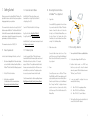
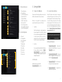
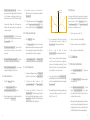
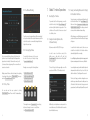
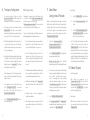
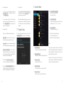
USER’S MANUAL
Table of contents
Getting Started . . . . . . . . . . . . . . . . . . . . . . . . . . . . . . . . . . .
Device Requirements . . . . . . . . . . . . . . . . . . . . . . . . . . . . .
Download Latest Software . . . . . . . . . . . . . . . . . . . . . . . . . . .
Firmware Update . . . . . . . . . . . . . . . . . . . . . . . . . . . . . . .
Connecting Evolution Interface to DitoGear™ moco Equipment . . . . . . . . .
Connecting to Evolution . . . . . . . . . . . . . . . . . . . . . . . . . . . .
The Interface . . . . . . . . . . . . . . . . . . . . . . . . . . . . . . . . . . . .
User Interface . . . . . . . . . . . . . . . . . . . . . . . . . . . . . . . . . . .
Main Window . . . . . . . . . . . . . . . . . . . . . . . . . . . . . . . . .
Timeline . . . . . . . . . . . . . . . . . . . . . . . . . . . . . . . . . . .
General Parameters . . . . . . . . . . . . . . . . . . . . . . . . . . . . . .
Axis Configuration . . . . . . . . . . . . . . . . . . . . . . . . . . . . . . .
Starting to Work . . . . . . . . . . . . . . . . . . . . . . . . . . . . . . . . . .
Precautions for Safe Operation . . . . . . . . . . . . . . . . . . . . . . . . .
Connection . . . . . . . . . . . . . . . . . . . . . . . . . . . . . . . . . .
Loading Settings and Curves . . . . . . . . . . . . . . . . . . . . . . . . . .
General Parameters . . . . . . . . . . . . . . . . . . . . . . . . . . . . . .
Axis Autodetection . . . . . . . . . . . . . . . . . . . . . . . . . . . . . .
Adding Axes Manually . . . . . . . . . . . . . . . . . . . . . . . . . . . . .
Axis Configuration . . . . . . . . . . . . . . . . . . . . . . . . . . . . . . .
Gyroscope . . . . . . . . . . . . . . . . . . . . . . . . . . . . . . . . . .
Calibration . . . . . . . . . . . . . . . . . . . . . . . . . . . . . . . . . . . . .
OmniSlider Axis Calibration . . . . . . . . . . . . . . . . . . . . . . . . . .
OmniHead Axes Calibration . . . . . . . . . . . . . . . . . . . . . . . . . .
Timeline Setup . . . . . . . . . . . . . . . . . . . . . . . . . . . . . . . . . . .
Setting up the Timeline Duration . . . . . . . . . . . . . . . . . . . . . . . .
Creating Keyframes . . . . . . . . . . . . . . . . . . . . . . . . . . . . . .
Editing Curves . . . . . . . . . . . . . . . . . . . . . . . . . . . . . . . . .
Undo / Redo . . . . . . . . . . . . . . . . . . . . . . . . . . . . . . . . .
Red Curve Warning . . . . . . . . . . . . . . . . . . . . . . . . . . . . . .
Deleting Keyframes . . . . . . . . . . . . . . . . . . . . . . . . . . . . . .
2
4
4
4
4
5
5
6
9
9
9
10
10
11
11
11
11
11
12
12
12
13
13
13
14
14
14
15
15
16
16
16
Global Timeline Operations . . . . . . . . . . . . . . . . . . . . . . . . . . . . .
Resetting the Timeline . . . . . . . . . . . . . . . . . . . . . . . . . . . . .
Saving and Loading Curves Into Software Memory . . . . . . . . . . . . . . .
Saving and Loading Curves and Settings into Evolution Interface . . . . . . . . .
Timelapse Configuration . . . . . . . . . . . . . . . . . . . . . . . . . . . . . .
Stop Motion Configuration & Playback . . . . . . . . . . . . . . . . . . . . . . . .
Motion Playback . . . . . . . . . . . . . . . . . . . . . . . . . . . . . . . . . .
Playback Delay . . . . . . . . . . . . . . . . . . . . . . . . . . . . . . . . . . .
Sound Options . . . . . . . . . . . . . . . . . . . . . . . . . . . . . . . . . . .
Troubleshooting . . . . . . . . . . . . . . . . . . . . . . . . . . . . . . . . . .
Loss of Wi-Fi connectivity . . . . . . . . . . . . . . . . . . . . . . . . . . .
Loss of Power at the Interface . . . . . . . . . . . . . . . . . . . . . . . . .
Using 3rd party power adapters . . . . . . . . . . . . . . . . . . . . . . . . . . .
Using DitoGear™ Power Packs . . . . . . . . . . . . . . . . . . . . . . . . . . .
Obtaining Support . . . . . . . . . . . . . . . . . . . . . . . . . . . . . . . . .
Limited Warranty . . . . . . . . . . . . . . . . . . . . . . . . . . . . . . . . . .
Privacy . . . . . . . . . . . . . . . . . . . . . . . . . . . . . . . . . . . . . . .
Miscellaneous . . . . . . . . . . . . . . . . . . . . . . . . . . . . . . . . . . .
17
17
17
17
18
19
19
20
21
22
22
22
23
23
23
24
27
27
1. Getting Started
1.2 Download Latest Software
Thank you very much for ordering DitoGear™ Evolution. We
hope that this motion controller will meet your expectations
bringing a great value to your productions.
Latest DitoGear™ Eveloution software can be
downloaded from Google Play Store (Android)
or Apple AppStore (iOS).
This manual includes instructions for using DitoGear™
Evolution mainly with DitoGear™ OmniSlider and DitoGear™
OmniHead. Please ensure to carefully read the safety instructions
and precautions contained in this manual and corresponding
gear manuals prior to the first use of the device.
1.1 Device Requirements
1.3 Firmware Update
In order to take full advantage of Evolution you’ll need:
In order to upgrade DitoGear™ Evolution firmware,
download the Evolution Firmware Updater and connect
the Evolution Interface to your Mac or PC computer
using an USB cable. The updater downloads the latest
firmware version automatically from DitoGear servers
and installs it on your interface. The updater provides
also access to previous firmware builds if needed.
2
DitoGear™ EvoIution Interface.
3
An Evolution-compatible tablet.
See link below for a list of recommended devices.
ditogear.com/products/evolution/features/
Check the manual below for details on updating firmware:
http://ditogear.com/Update_Evolution_Firmware_Manual
Signal cable
1
Connect an RJ45 type signal cable for each of axes
of your motion control kit to DitoGear™ Evolution
channels. Connect the other end of each cable
to Input 1 port of dedicated Breakout Boxes, one
for each of devices. Use 2 signal cables for the
OmniHead, one for each of axes and connect them
on Input 1 & 2 of the Breakout Box.
AppStore direct link is http://bit.ly/DGEvoIOS
Google Play direct link is http://bit.ly/DGEvoAnd
This manual was released on 2014/03/04.
At least one of existing DitoGear™ motion control devices,
such as: OmniSlider, OmniHead, LensDrive, Modulo or
DitoGear™ Motion Control Kits for 3rd party equipment.
1
Search for “DitoGear Evolution” to find the app.
Latest DitoGear™ product manuals can always be found
at: ditogear.com/user-manuals
1
1.4 Connecting Evolution Interface
to DitoGear™ moco Equipment
2
Shutter release cable
Connect a shutter release cable to one of Sync
ports (2.5mm micro jack) of any of the the Breakout
Boxes. Connect the other end to your camera. This
step is optional.
3
2
3
1
DitoGear Motion
Control Device
1.5 Connecting to Evolution
1
Turn on your Android or iOS Evolution-compatible tablet device.
2
Go to system settings and find WiFi section.
3
Evolution Interface works on a DHCP basis,
therefore you only need to choose the network
and enter password. The default network name is
“DitoGear”, pass is “DitoGear”.
4
In case you wanted to configure the access
manually do the following:
Power
Connect the power source – a DitoGear™ Power
Pack 7Ah/14Ah, an AC/DC power adapter or a 3rd
party compatible power source via PowerSplitter or
PowerScorpion to the Power port of each Breakout
Box. If using OmniSlider, for high-performance
operation connect one of power cables directly
to the Power port of the OmniSlider instead of its
Breakout Box.
4 . 1
4 . 2
4 . 3
5
4
Enter 192.168.0.1 as a gateway address
Enter 192.168.0.1 as a DNS address
Enter 192.168.0.100 as an IP address
This should be sufficient and you should be able to
connect to DitoGear WiFi network.
5
2. The Interface
1
2
3
4
The antenne
USB Port
Interface Reset Button
Axes Outputs
3
1
4
2
6
7
3. User Interface
32
36
44
35
37
33
38
41
39
40
34
42
43
3
2
6
5
4
1
7
8
9
10
16
13
14
17
12
15
18
19
20
21
22
23
24
31
30
25
27
28
29
26
50
49
45
46
47
51
48
52
11
3.1 Main Window
1
2
3
4
5
6
7
8
9
10
11
12
13
14
15
16
17
18
19
Connected Axis Button
Inactive Axis
Active Axis
Low Battery State
Battery Level Indicator
Undo / Redo
Keyframe List
Maximize timeline
Screen Lock
Preset Manager
Settings
Operation Mode Label
Controls View Tab
Configure Timelapse Tab
Configure Stop Motion Tab
Connection Status
Pause Button
Play Button
Loop Playback Toggle
20
21
22
23
24
25
26
27
28
29
30
31
32
33
34
35
36
37
38
Go to First Keyframe
Go to Previous Keyframe
Go to Next Keyframe
Go to Last Keyframe
Add Keyframe
Remove Keyframe
Mark Keyframes
Calibration In-Point
Calibration Out-Point
Real-time operation slider
Reset Button
Take Pictures Button
Status Window
Details Header
Details Window
First Keyframe
Playhead
Timeline Scale
End Keyframe
39
40
41
42
43
44
45
46
47
48
49
50
51
52
53
54
55
56
Axis Position Marker
Axis Scale
Keyframe
Keyframe Handle
Motion Curve
Playback Progress
Number of Shots
Exposure
Interval
Enable Bulb Ramping
Bulb Ramping Exposures Setup
Timelapse Mode Enable
Continuous Mode
Drive-Shoot-Drive Mode
Frames Per Second
Number Of Shots
Stop Motion Exposure
Stop Motion Mode Enable
3.2 Timeline
56
53
8
54
55
9
3.3 General Parameters
57
57
58
59
60
61
62
63
64
65
66
58
59
60
61
62
63
64
65
67
67
68
69
70
71
72
73
74
75
76
70
71
72
73
4.1 Precautions for Safe Operation
4.3 Loading Settings and Curves
Please read and follow the guidelines below to use the
Evolution safely and ensure its best performance.
DitoGear™ Evolution Interface allows for storing and
recalling the last program used in the memory of the
interface (regardless of Save & Load features of the app).
On connection, the app prompts you to confirm recalling
the last program used from the interface memory. Click
“yes” to recall the last program stored in the interface or
click ‘cancel’ to start programming from scratch. Learn
more in “Saving and Loading Curves and Settings into
Evolution Interface(7.3)” section.
DitoGear is not responsible for any damage to the
equipment caused by improper use of the device.
1
69
Axes List
Configured Axis
Axis Configuration
Show Axis
Battery Status
Mirror Mode
Axis Name
Device Class
Device Type
Motion Limit
OmniSlider
Note that calibrating for a length greater than
the physical length of the OmniSlider or setting
the In-point and working length that fall outside
of physical movement limits may lead to an
unexpected collision of the trolley with an end of
the slider. It can result in equipment damage.
3.4 Axis Configuration
66
68
General Parameters
Timehead Follow
Connection Auto Detection
Clapperboard Offset
Clapperboard String
Shutter Connection Type
Gyroscope Switch
Control Preselected Axes
Horizontal Tilt Axis Assigment
Vertical Tilt Axis Assigment
4. Starting to Work
2
Lens Drive
It is recommended to calibrate a DitoGear™ LensDrive
the same method as described in “OmniHead
Custom Calibration(5)”. In case of lenses that have
a limited angle of rotation, exceeding this limit may result in
damage to the equipment.
76
10
1
“Timehead Follow (58)” - Automatically
synchronizes activated devices to the current
“Playhead (36)” position.
2
“Connection Auto Detection (59)” - Automatic
detection of plugged axes. Get more information in
next section: “Axis Autodetection(4.5)”.
3
“Clapperboard Offset (60)” - Time offset between
the clapperboard clap and playback start.
4
“Clapperboard String (61)” - Configurable text
displayed on the clapperboard.
4.2 Connection
74
75
4.4 General Parameters
Run the Evolution app and wait until
“Connection Status (16)” turns yellow.
11
“Shutter Connection Type (62)” - Select an
appropriate shutter triggering method depending
on the hardware configuration (Legacy 4-pin
shutter release ports or RJ-45 / Minijack cabling).
4
5
Inappropriate settings will not damage your
hardware, but camera may become unresponsive
or behave erratically.
6
7
8
9
“Gyroscope Switch (63)” - Use tablet built-in
gyroscope to move assigned axes. Learn more in
“Gyroscope(4.8)” section.
“Vertical Tilt Axis Assigment (66)” - select an axis
actuated by tilting the tablet vertically.
4.5 Axis Autodetection
1
Click the “Settings (11)” button.
2
On “General Parameters (57)” check
“Connection Auto Detection (59)” option.
3
12
Now all plugged axes will be added automatically
and shown on the “Axes List (67)”.
Mirror Mode
Reflection Axis
Curve without mirror mode
To manually remove any axis from “Axes List (67)”,
uncheck “Connection Auto Detection (59)” option,
then remove the Axis by clicking “Show Axis (70)”.
4.6 Adding Axes Manually
1
Click “Settings (11)” button.
2
On the “Axes List (67)” select an axis you want to
add. Axis numbers appeared on the screen are related
to the channels appearing on the Interface. All axes
connected to the device need to be configured.
“Control Preselected Axes (64)” - check to control
preselected axes. Uncheck to control currently
active axis.
“Horizontal Tilt Axis Assigment (65)” - select an
axis actuated by tilting the tablet horizontally.
Any further connection or disconnection of
additional axes will be automatically updated on
“Axes List (67)”.
3
4
5
2
3
To configure all settings for an axis, click “Settings (11)”
button, and select the axis from “Axes List (67)”.
6
To display the battery status on
the
“Connected Axis Button (1)” select “Battery Status (71)”.
To reverse the direction of the device, click
“Mirror Mode (72)”. This will change only Operation
Direction, without affecting playback or position of
“Playhead (36)” on the timeline. The following picture
depicts visually how Mirror Mode works:
7
Gyroscope control lets you to operate one or two axes at a
time by tilting your tablet horizontally and vertically. To turn
gyroscope mode on/ off click “Settings (11)” button, on
“General Parameters (57)” check “Gyroscope Switch (63)”
and choose one of available options:
Disable - gyroscope control is off
It is recommended to label the axis according
to the devices name. In order to do that, click
“Axis Name (73)” and type a suitable name.
2
Smooth - low response on tablet tilting
3
Medium - medium response on tablet tilting
Choose a class of device by clicking
“Device Class (74)” and selecting it from the list.
4
Fast - quick response on tablet tilting
Note: if you have a different device than shown
in the list, select Custom Device. Configuration
options will be activated automatically. Contact
DitoGear™ support for more detailed information
on the settings for your custom device.
In “Axis Configuration (69)” click “Show Axis (70)”
to activate and show this axis in the main app window.
4.8 Gyroscope
1
Time / Operation Direction
4.7 Axis Configuration
1
Curve with mirror mode
Axis Position
5
Choose type of device by clicking “Device Type (75)”
and selecting it from the list. To define a custom length,
select Custom Length. Set the value of custom length in
“Motion Limit (76)”.
5. Calibration
5.1 OmniSlider Axis Calibration
1
Click “Connected Axis Button (1)” to activate the
OmniSlider axis.
2
Click “Calibration In-Point (27)” to activate calibration
start position mode.
3
Move “Real-time operation slider (29)” or tilt the
tablet (if “Gyroscope Switch (63)” is on) to jog the
trolley to the end of track (close to the motor box) or
to another desired In- position.
4
If the playhead is in the starting position, the end position
can only be reached by ordering the device to move to
the right. However, if you try to move the device to the
left, the Mirror Mode will be turned automatically on.
After editing the axis, return to the main window using
a system back button, appropriate for a specific
tablet (“Done” on iOS).
13
5
Click “Calibration In-Point (27)” once again to
deactivate calibration mode and click “Yes” to confirm
the In-point calibration. End position is calculated
automatically basing on type and length of the
device as entered in “Settings (11)”.
4
5
6
Click “Calibration In-Point (27)” again to deactivate
calibration start position mode and click “Yes” to
confirm. Out-point will be calculated automatically
at 360 degrees from the in-point.
OmniHead Custom Calibration
OmniSlider Custom Calibration
5 . 1
6 . 1
6 . 2
6 . 3
If the start position is set in a different location
than next to the motor box, or if you want to
set a different length than entered in the axis
settings, click “Calibration Out-Point (28)”.
5 . 2
5 . 3
Click “Calibration Out-Point (28)” to deactivate
calibration mode and click “Yes” to confirm.
Note: Both OmniHead axes need to be activated in
“Settings (11)”. Set it up as OmniHead Pan and OmniHead
Tilt in “Device Type (75)”. It’s recommended to name axes as
“Pan” and “Tilt” to know clearly which axis you’re working on.
1
Click the first “Connected Axis Button (1)” (it should be pan) to activate it.
2
Click “Calibration In-Point (27)” to activate the
in-point calibration mode.
5 . 4
14
Move “Real-time operation slider (29)” or tilt the
tablet (if “Gyroscope Switch (63)” is on) to jog the
head to desired in-point position.
Note: You can change the timeline duration at any time,
but the best workflow is when you set it up just before
creating keyframes.
6.2 Creating Keyframes
Recommended method:
Move “Real-time operation slider (29)” or tilt
the tablet to jog the head to desired position.
Click “Calibration Out-Point (28)” again to deactivate out-point calibration mode, then click “Yes” to confirm.
1
Turn off “Timehead Follow (58)”.
2
Move “Playhead (36)” to time position where you
want to create a keyframe.
3
Click “Inactive Axis (2)” to activate it.
4
Move “Real-time operation slider (29)” or tilt the
tablet (if “Gyroscope Switch (63)” is on) to jog the
device to a desired position.
Repeat the steps above to calibrate the second axis.
Note: You can calibrate two axes at a time using gyroscope
controls. Check section: “Gyroscope(4.8)” for details.
6. Timeline Setup
5
Click “Mark Keyframes (26)” button to create the keyframe.
6.1 Setting up the Timeline Duration
6
Click “Active Axis (3)” to finish process for this axis.
7
Repeat these steps for each of axes.
1
3
Fill it in and click “Save”.
Alternative method:
1
Grab “Playhead (36)” and move it to a position, where
you want to create the keyframe.
2
Click “Inactive Axis (2)” to activate it.
3
Click “Add Keyframe (24)” button to add the
keyframe at the crossing of “Playhead (36)” and
“Motion Curve (43)”.
4
Deactivate axis by clicking “Active Axis (3)”.
Take the following steps for each axis independently:
Move “Real-time operation slider (29)” or tilt
the tablet to run the trolley to desired position.
5.2 OmniHead Axes Calibration
Out-point can be overriden manually to limit operation length by clicking “Calibration Out-Point (28)”.
2
Double tap the timeline and the following pop-up will appear:
Tip: If you want to create keyframes for each of axes at
the same “Playhead (36)” position, you can click the
“Mark Keyframes (26)” button when all axes are set up
and activated.
6.3 Editing Curves
You can edit curves only for one axis at the same time.
Select an axis you want to edit by clicking one of
“Inactive Axis (2)”. You can change a curve shape by moving
“Keyframe Handle (42)”. It is possible to change a position of
any “Keyframe (41)” just by dragging it.
For more accurate curves editing, follow the steps below:
•• click “Maximize timeline (8)” button to enlarge
the timeline.
•• Pinch the screen to zoom-in around the desired
keyframe.
•• touch and hold desired “Keyframe (41)” or
“Keyframe Handle (42)” and set new position of
the point in the pop-up window (see below).
•• open “Keyframe List(7)”. You will find all
keyframes there. The handles are right indented
and placed around their keyframe parents, so you
can locate them easily. To edit keyframe or handle in
the list, touch and hold until following pop-up appears:
15
7. Global Timeline Operations
6.5 Red Curve Warning
7.1 Resetting the Timeline
If you want to start from the beginning, you need to
reset the timeline by clicking “Preset Manager (10)”
and choosing “Reset all paths to begin position”. Your
calibration is still saved but all curves are restored
to a default position.
If a motion curve or its segment turns red, the movement will
not be performed due to the exceeded maximum speed of the
motor. In this case it is recommended to change the timeline
length or the curve shape.
Keyframes are stored in XML/CSV files types.
6.6 Deleting Keyframes
It is recommended to set up the very first and very last
keyframe of each of axes that way, that its tangent was
aligned more horizontally. Otherwise there may be a bit
of jerkiness at the very beginning of the movement due to
excessive acceleration.
You can delete keyframes only for one axis
at a time. Choose a specific axis by clicking
“Connected Axis Button (1)”.
Editing curves will influence the selected axis by live updating
it according to the position of “Playhead (36)” unless you
uncheck “Timehead Follow (58)” option.
“Go to First Keyframe (20)”,
“Go to Previous Keyframe (21)”,
“Go to Next Keyframe (22)”
“Go to Last Keyframe (23)”.
6.4 Undo / Redo
Navigate across using the following buttons:
20
21
22
7.2 Saving and Loading Curves Into
Software Memory
In order to save or load motion curves (to the
tablet memory - either flash or SD card), click
“Preset Manager (10)” button and choose “Export paths”
or “Import paths”.
To choose file type, click in the upper-right corner of the
pop-up to select XML or CSV format (see below).
7.3 Saving and Loading Curves and Settings
into Evolution Interface
You can also save your keyframes and settings directly
into Evolution Interface. Click “Preset Manager (10)”
button and choose Save curves and settings in the
Evolution Interface memory. Those settings contain all
six curves, timeline duration and axes settings.
After loading you can edit paths during your work, but if
you disconnect the power from the interface, all changes
will be gone.
In case Evolution Interface crashed, the curves are
reloaded from the tablet to the Evolution Interface
automatically right after reconnecting.
In case of killing the application via system task manager, current
keyframes are always saved in the memory of the tablet.
In case of application crash, you will be asked to load points
and parameters from the device. If you choose “Yes, load
data from the device”, lost settings will be recovered.
The only risk of losing your timeline configuration occurs
when the app crashes at the same time with power loss
of the Interface. Therefore the risk of losing your current
program (even if you did not explicitly saved it) is very small.
23
You can undo and redo any operation by clicking
“Undo / Redo(6)” buttons. There is limit of 10 backward steps.
This navigation moves “Playhead (36)” over existing
keyframes allowing to remove or modify them.
Click “Remove Keyframe (25)”.
16
Additionally, current keyframes are always saved to a
non-volatile memory of the Evolution Interface and are
stored in the tablet memory.
17
8. Timelapse Configuration
1
2
Set a desired number of frames by clicking
“Number of Shots (45)” field. Enter a value using
the keyboard. Click “Done” to confirm the value.
Set the exposure time for each frame by clicking
“Exposure (46)” field. Enter a value using the
keyboard. Please note that you need to enter a value
in seconds. Click “Done” to confirm the value.
3
Note that this setting will be efficient only if you set
your camera to bulb exposure mode. Otherwise,
set a desired exposure time in your camera and use
100ms as a trigger value.
4
An interval will be determined automatically based
on “Number of Shots”, “Exposure” and the length
of the Timeline. To change length of the interval
between frames, click “Interval (47)”. This change
will modify the number of frames.
Bulb Ramping Settings
Changing the exposure values while taking shots
is possible by clicking “Enable Bulb Ramping (48)”.
Create an exposure curve by clicking “Bulb Ramping Exposures Setup (49)”. Your camera needs
to be set to Bulb mode for that method to work.
The way of creating, editing, and deleting keyframes in
bulbramping settings is similar to the main timeline.
To set up bulbramping, select an appropriate axis.
Remember to connect the shutter release cable
from any of BreakOut Boxes to your camera.
1
If you are in “Controls View Tab (13)”, or
“Configure Timelapse Tab (14)”, go to
“Configure Stop Motion Tab (15)”.
2
Set up the “Maximum Exposure Value” as the
maximum value of the time of exposure in your
shot. It corresponds to the highest position of the
curve. Please note that you should enter a value in
seconds.
2
Set up “Frames Per Second (53)”. This is the framerate,
in which you want to take a shot.
3
“Number Of Shots (54)” will be calculated
automatically based on FPS and the length of timeline.
The lowest value is the smallest time possible to achieve
by your camera. The approximate value is 25ms. It
corresponds to the lowest position of the curve.
4
To create a stop motion sequence with bracketing
technique, change the default value of the exposure
time so that it exceeded the total exposure
time of all subexposures. Set the bracketing
mode and continuous shooting in your camera.
In “Stop Motion Exposure (55)” set an appropriate
time value to be sure that the camera will take all
bracketing pictures in each stop.
Note: Changing any of the following parameters
(exposure, timeline, interval length) influences the
number of frames.
6
18
If you want the camera to shoot while moving,
select “Continuous Mode (51)”. If you want
the camera to stop to take each shot, select
“Drive-Shoot-Drive Mode (52)”.
Select “Timelapse Mode Enable (50)” and your
shot will be ready to go.
4
Add keyframes indicating them by “Playhead (36)”
and using the buttons at the bottom right of the
screen.
5
Change the shape of curves by dragging the
keyframes and handles.
6
After editing the exposure curves, go back to the
main window using the system “back button” or
“done” in iOS.
7
Before you start working with stop motion, remember
that (contrary to the Drive Mode and Timelapse Mode),
a length of the timeline does not affect operating time,
but rather the length of actual footage acquired as
calculated on a basis of the parameters specified in
“Configure Stop Motion Tab (15)”.
1
3
5
9. Stop Motion
Configuration & Playback
5
Select “Stop Motion Mode Enable (56)”.
6
Go to “Controls View Tab (13)”, click “Reset Button (30)”
and wait until the axis achieved home position. You
can check it on the “Status Window (32)”.
Run Playback
7 . 1
Click the “Play Button (18)” to start Playback.
7 . 2
Click the “Take Pictures Button (31)” to take
a shot.
7 . 1
Click the “Go to Previous Keyframe (21)” or
“Go to Next Keyframe (22)” to move motor
position to next or previous stop.
Tip: To check if the picture was taken, or whether
a motion of the axes was made, check the
“Status Window (32)”. An info “# Shot (s) Taken”
means that the number of # pictures was taken
since the last stop. Each time you pass to the next
position, a following information will appear: “Position
Achieved / Take Pictures”. Go to the detail view to
check out the total amount of shots taken.
10.Motion Playback
1
Check all parameters
After setting the parameters, go to
“Controls View Tab (13)”. Make sure that the
“Operation Mode Label (12)” shows the desired
mode. Press the “Reset Button (30)” to jog all the
axes to their starting positions.
2
Run playback
After the device set all axes in a Home Position,
you can enable motion playback by clicking the
“Play Button (18)”.
19
3
4
Pause the playback
5
Lock the tablet
In order to pause playback temporarily
“Pause Button (17)”. To reactivate the movement
use “Play Button (18)”.
It is recommended to lock the buttons of the application
during playback by toggling “Screen Lock (9)”. This will
also disable gyroscope function.
You can change curves on the timeline during
pause, but remember that any changes of curves
nearby “Playhead (36)” will cause jump to a new
position of the edited curve.
Note: after activating the playback you can also turn
the application, screen or tablet off. The program will
be sent to the device and executed without app
assistance.
Looping playback
11. Playback Delay
There are three different loop playback modes:
To set the exact playback start time, touch and hold
“Play Button (18)” button. There are 2 following options:
12.Sound Options
82 Interval Sound Playback Toggle
77
78
79
80
Set time interval between each sound. Chose one of
available options: 1, 5, 10, 30, 60 seconds.
84 Sync Sounds Repeat
Options for sync sounds repeat
82
83
84
77 Sound Parameters
Looped - Simple Rewind - the movement is
executed time after time, but on the way back the
curves are ignored and all axes are rewinded to the
starting position using simplest path.
83 Sound Interval Duration
81
Once - Paths - the movement is executed once
forth and back using designed motion paths.
Looped - Paths - the movement is executed time after
time forth and back using designed motion paths.
Plays a sync sound repeatedly
in a specified interval
Contains all sound options as described below
78 Playback Start Sound
•• Play the sound for the first playback,
no sound for subsequent loops
•• Play the sound for every playback cycle
Notes:
Using a custom mp3 file may result in an offset of the
actual sound playback start due to ‘audio padding’ of the
mp3 file standard. The offset should be below 1-frame
threshold and should be constant.
Plays a sync sound on the beginning of the timeline
•• Click and hold “Loop Playback Toggle (19)”.
Choose a desired playback mode and press OK.
79 Default Sound Type
•• Press again “Loop Playback Toggle (19)” button to
activate loop mode. Loop mode can be turned on
either before starting playback or during pause.
80 Custom Sound Type
Plays default 220Hz sound
Using audio for video syncing is not the most perfect
solution in general, so in the future we plan on adding more
reliable sync methods using visual means.
Choose this option to use your own sound file
81 Playback End Sound
Plays a sync sound on the end of the timeline
20
21
13.Troubleshooting
14.Using 3rd Party Power Adapters
13.1 Loss of Wi-Fi connectivity
DitoGear recommends using original DitoGear™ AC/DC power adapters and batteries.
While using a 3rd party adapter make sure it meets the requirements detailed in technical specifications table.
It is possible to lose the connection between the device and the tablet. If the device is still working, lack of connection
will not affect the job, because after activating the playback the program is sent to the device and executed without app
assistance. The application is used mainly for viewing the status of a job or for programming the shot.
Reasons for losing connection:
•• Excessive distance between the tablet and the Evolution Interface.
Try bringing your tablet closer to Evolution Interface.
•• The tablet is located in a different room or building than the Evolution Interface.
Try bringing your tablet closer to Evolution Interface.
•• Loss of power in the device. Check the power of Evolution Interface and all motion control devices
•• Replacing or disconnecting one of signal cables. The application should retrieve the connection after a short time.
•• Damage to a signal cable. Make sure all signal cables are in proper condition.
•• Another network of higher priority was detected. Try assigning the highest priority to DitoGear™ Evolution
network or remove other networks from the tablet Wi-Fi settings by using “Forget this network” option.
In case any of the above mentioned solutions did not help bringing back the connection, contact the DitoGear™ support team.
Caution!
DitoGear is not responsible for any damage or failures caused by the use of a 3rd party power supply adapter.
15.Precautions for Safe Use of DitoGear™ Power Cables
Power cables cannot be looped during operation due to insufficient heat rejection that can cause melting of the cable
insulation and ultimately its failure. Remember to disconnect all power cables after use, especially during transportation.
16.Using DitoGear™ Power Packs
DitoGear™ Power Pack 7Ah/14Ah and DitoGear™ PowerBox include gel type lead acid batteries, that have a low
voltage operating limit. When you discharge the battery below that limit, the irreversible chemical processes occur and
the recharging performance can be affected. It is recommended not to fully discharge the battery.
The lead acid battery will self-discharge slowly over time. Leaving the battery for more than 3 months without recharging
may result in damage. Remember to recharge the battery at least every 3 months.
13.2 Loss of Power at the Interface
17. Obtaining Support
If that happens, the interface will also lose the connection with the tablet. In case the software does not set up a connection
automatically, you will need to enter the network settings on the tablet and connect to the DitoGear network manually.
In case of any technical issues that can’t be solved by carefully reading the manuals do not hesitate
to contact us at [email protected]
Saved curves won’t be lost but all devices will need to be calibrated again.
18.Limited Warranty
DitoGear One (1) Year Limited Warranty
For DitoGear Products Only
Consumer rights and restrictions.
For consumers, who are covered by consumer protection laws or regulations in their country of purchase or, if different,
their country of residence, the benefits conferred by this warranty are in addition to all rights and remedies conveyed
by such consumer protection laws and regulations. This warranty does not exclude, limit or suspend any rights of
consumers arising out of non-conformity with a sales contract. However, as described below, DitoGear disclaims
statutory and implied warranties to the extent permitted by law, and in so far as such warranties cannot be disclaimed, all
such warranties shall to the extent permitted by law be limited in duration to the duration of the express warranty described
below and to the repair or replacement service as determined by DitoGear in its sole discretion. Some states (countries and
provinces) do not allow limitations on how long an implied warranty or condition may last, so the limitations described
above may not apply to you. This warranty gives you specific legal rights, and you may also have other rights that vary
from state to state (or by country or province). This limited warranty is governed by and construed under the laws of the
country in which the product purchase took place. DitoGear, the warrantor, under this limited warranty stands for DitoGear™ Robert
Paluch, ul.Krańcowa 30, 62-002 Suchy Las, Poland.
Warranty.
DitoGear’s warranty obligations for this hardware product are limited to the terms set forth herein. DitoGear
warrants this DitoGear-branded hardware product against defects in materials and workmanship under
normal use for a period of one (1) year from the date of retail purchase by the original end-user purchaser
(“Warranty Period”). If a hardware defect arises and a valid claim is received within the Warranty Period,
at its option and to the extent permitted by law, DitoGear will either (1) repair the hardware defect
at no charge, using new or refurbished parts that are equivalent to new in performance and reliability, (2)
exchange the product with a product that is new or refurbished that is equivalent to new in performance
and reliability and is at least functionally equivalent to the original product, or (3) refund the purchase
price of the product. DitoGear may request that you replace defective parts with user-installable new
or refurbished parts that DitoGear provides in fulfillment of its warranty obligation. A replacement product or part, including a user-installable part that has been installed in accordance with instructions
provided by DitoGear, assumes the remaining warranty of the original product or ninety (90) days from the date of
replacement or repair, whichever provides longer coverage for you.
When a product or part is exchanged, any replacement item becomes your property and the replaced item
becomes DitoGear’s property. Parts provided by DitoGear in fulfillment of its warranty obligation must
be used in products for which warranty service is claimed. When a refund is given, the product for which the refund is
provided must be returned to DitoGear and becomes DitoGear’s property.
Exclusions and limitations.
To the extent permitted by law, this warranty and the remedies set forth above are exclusive and in lieu
of all other warranties, remedies and conditions, whether oral, written, statutory, express or implied.
As permitted by applicable law, DitoGear specifically disclaims any and all statutory or implied warranties, including,
without limitation, warranties of merchantability and fitness for a particular purpose and warranties against hidden or latent
defects. If DitoGear cannot lawfully disclaim statutory or implied warranties then to the extent permitted by law, all such
warranties shall be limited in duration to the duration of the express warranty and to the repair or replacement service as
determined by DitoGear in its sole discretion. Some states (countries and provinces) do not allow limitations on how long
an implied warranty or condition may last, so the limitations described above may not apply to you. No DitoGear reseller,
agent, or employee is authorized to make any modification, extension, or addition to this warranty. If any term is held to be
illegal or unenforceable, the legality or enforceability of the remaining terms shall not be affected or impaired.
This Limited Warranty applies only to hardware products manufactured by or for DitoGear. The Limited Warranty does
not apply to any non-DitoGear hardware products even if packaged or sold with DitoGear hardware. Manufacturers or
suppliers, other than DitoGear, may provide their own warranties to the end user purchaser, but DitoGear, in so far as
permitted by law, provides their products “as is”.
DitoGear does not warrant that the operation of the product will be uninterrupted or error-free. DitoGear is not
responsible for damage arising from failure to follow instructions relating to the product’s use.
This warranty does not apply: (a) to consumable parts, such as batteries, unless damage has occurred due to a defect in
materials or workmanship; (b) to cosmetic damage, including but not limited to scratches, dents and broken elements on
ports; (c) to damage caused by use with non-DitoGear products; (d) to damage caused by accident, abuse, misuse, liquid
contact, fire, earthquake or other external causes; (e) to damage caused by operating the product outside the permitted
or intended uses described by DitoGear; (f) to damage caused by service (including upgrades and expansions) performed
by anyone who is not a representative of DitoGear; (g) to a product or part that has been modified to alter functionality or
capability without the written permission of DitoGear; (h) to defects caused by normal wear and tear or otherwise due to
the normal aging of the product.
Except as provided in this warranty and to the extent permitted by law, DitoGear is not responsible for direct,
special, incidental or consequential damages resulting from any breach of warranty or condition, or under any other
legal theory, including but not limited to loss of use; loss of revenue; loss of actual or anticipated profits (including loss of
profits on contracts); loss of the use of money; loss of anticipated savings; loss of business; loss of Opportunity; loss of
goodwill; loss of reputation; loss of, damage to or any indirect or consequential loss or damage howsoever caused including the
replacement of equipment and property. The foregoing limitation shall not apply to death or personal injury claims, or
any statutory liability for intentional and gross negligent acts and/or omissions. Some states (countries and provinces) do
not allow the exclusion or limitation of incidental or consequential damages, so the above limitation or exclusion may not
apply to you.
Obtaining warranty service.
DitoGear will provide warranty service either (i) at an DitoGear Retail or DitoGear Authorized Service Provider (“ASP”)
location, where service is performed at the location, or the DitoGear Retail or ASP may send the product to an DitoGear
repair service location for service, (ii) by sending you prepaid way bills (and if you no longer have the original packaging,
DitoGear may send you packaging material) to enable you to ship the product to DitoGear’s repair service location for
service, or (iii) by sending you customer installable new or refurbished replacement product or parts to enable you to
service or exchange your own product (“DIY Service”). Upon receipt of the replacement product or part, the original
product or part becomes the property of DitoGear and you agree to follow instructions, including, if required, arranging the
return of original product or part to DitoGear in a timely manner. When providing DIY Service requiring the return of the
original product or part, DitoGear may require a credit card authorization as security for the retail price of the replacement
product or part and applicable shipping costs. If you follow instructions, DitoGear will cancel the credit card authorization,
so you will not be charged for the product or part and shipping costs.
If you fail to return the replaced product or part as instructed or the replaced product or part is not eligible for warranty
service, DitoGear will charge the credit card for the authorized amount.
Please access and review the online help resources at the DitoGear website (www.ditogear.com) and contained in the
product manual before requesting warranty service. If the product is still not functioning properly after making use of these
resources, please contact DitoGear at [email protected].
Service options, parts availability and response times may vary according to the country in which service is requested.
Service options are subject to change at any time. You may be responsible for shipping and handling charges if the
product cannot be serviced in the country in which service is requested. If you seek service in a country that is not the
country of purchase, you will comply with all applicable import and export laws and regulations and be responsible for all
custom duties, VAT. and other associated taxes and charges. For international service, DitoGear may repair or exchange
defective products and parts with comparable products and parts that comply with local standards. In accordance with
applicable law, DitoGear may require that you furnish proof of purchase details before receiving warranty service.
19.Privacy
DitoGear will maintain and use customer information in accordance with the DitoGear Customer Privacy Policy available
at ditogear.com/legal/privacy-policy/.
20.Miscellaneous
Trademarks and copyrights
DitoGear™, DitoGear™ OmniController, DitoGear™ Evolution, DitoGear™ Trito , DitoGear™ OmniSlider, DitoGear™
OmniHead and DitoGear™ LensDrive, DitoGear™ Modulo are trademarks of Dito Gear Robert Paluch ul.Krańcowa 30,
62-002 Suchy Las, Poland. Unauthorised use is strictly prohibited. All other trademarks referenced in this manual are used
only for informative purposes and are property of their respective owners.
Disposal and recycling information
The device and all batteries included with it must be disposed of properly according to local laws and regulations. The product
must be disposed of separately from the household waste. When your product reaches its end of life, contact DitoGear or your
local authorities to learn about recycling options.
W W W. DITOGE AR .COM