1
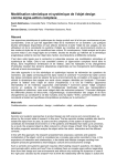
User-centered methods are insufficient for safety critical systems Harold Thimbleby Director, Future Interaction Technology Laboratory Swansea University Wales, SA2 8PP [email protected] Abstract. The traditional approaches of HCI are essential, but they are unable to cope with the complexity of typical modern interactive devices in the safety critical context of medical devices. We outline some technical approaches, based on simple and “easy to use” formal methods, to improve usability and safety, and show how they scale to typical devices. Specifically: (i) it is easy to visualize behavioral properties; (ii) it is easy to formalize and check properties rigorously; (iii) the scale of typical devices means that conventional usercentered approaches, while still necessary, are insufficient to contribute reliably to safety related interaction issues. Keywords: Human–Computer Interaction, Interaction Programming, Usability Engineering, Safety Critical Interactive Devices 1. Introduction It is a commonplace observation that interactive devices are not easy to use, nor even always safe — cars and the use of entertainment electronics in cars being a familiar example. While we all like mobile phones, it is probably true that nobody fully understands their phone. Users may not know everything about a phone, but it is sufficient that phones do enough for their users. Although there is no reason why every user needs to be able to do everything, even with the subset of features each user knows and feels comfortable with there are still usability issues. The regular experience of usability problems stimulates the user into coveting the latest model, which promises to solve various problems, and anyway provides many new tempting features. Evidently, the successful business model and user experience of consumer devices is different to what is appropriate for the design of safety critical and medical devices. To contrast it explicitly: it is no use a nurse having problems with a defibrillator and therefore wishing to buy a new one! In this case, the nurse has a very limited time to work out how to use the device; its incorrect use may be fatal. Of course, the nurse should be well-trained, another difference between medical and consumer device design. Devices have to work and hence, necessarily, they have to be specified and programmed. Some evidence, unfortunately, suggests that medical device designers apply consumer device practices rather than safety critical practices. Medical devices are complex. They are not just more complex than their users can handle but they are also more complex than the manufacturers can handle. User manuals for medical devices often contain errors, suggesting weaknesses in the design process — and also bringing into question the reliability of user training, since it is based on the manufacturer’s accurate models of the systems. For some concrete examples see [17]. The traditional HCI response to these well-recognized usability problems is to concentrate on the problems as they face the user. Working with users, we get insight into training, user misconceptions, user error, recovery from error, and so on. This is a sufficient challenge for research in HCI, but in industrial development the insights from evaluation need feeding back into the design process to improve designs: this is iterative design. Iterative design properly informed by the user experience is called user-centered design (UCD). The arguments for UCD and iterative design have been widely made; outstanding references being Landauer [10] and Gould & Lewis [5]. Gould & Lewis is now a classic paper, proposing the importance of three key ideas: (i) early and continual focus on users; (ii) empirical measurement of usage; (iii) iterative design whereby the system (simulated, prototype, and real) is modified, tested, modified again, tested again, and the cycle is repeated again and again (i.e., iterative design). More recent work [3] emphasizes the important role of design in medical device design, though this is essentially ergonomics and industrial design. The continued problems with usability has led to an explosion in alternative UCD methods: task analysis, contextual design, activity theory, cognitive walkthrough, heuristic evaluation, questions-options-criteria, ecological methods; more theoretically-motivated methods such as information foraging; and numerous concepts, from scenarios and diary techniques to grounded theory. Methods may be theoretical (e.g., any of the numerous extensions and variations of GOMS-like approaches), done by experts without users (inspection methods), or involve users (test methods). All HCI textbooks cover a representative range of such techniques; [8] is a convenient review. The hurdles in the way of the adoption of UCD methods in industry has led to much work in the politics of usability: how does an industry that is driven by technology come to terms with UCD methods? How can usability experts have the political power in order to ensure their empirically-informed insights are adopted? According to some commentators, just providing technical designers with actual observations of use (such as videos) is enough to make them “squirm” sic [20] and hence will motivate them to adopt or support UCD methods within their company. Indeed, words like “squirm” are indicative of the problems usability professionals perceive: technologists seem to be the problem; they need to understand the value of usability work; and they need to be told what to do by the people who understand users [10]. 1.1 Overview of this paper In this paper we review the role of UCD applied to a simple safety critical device. The device is simple but it is beyond conventional UCD techniques to manage. Our conclusion is that UCD is necessary but is far from sufficient; indeed the conventional emphasis on UCD diverts attention from technical problems that must also be solved. Technologists’ lack of concern for UCD is not the scapegoat. The bottleneck in design is the failure to use professional programming methodologies. Fig 1. The Fluke 114, showing the LCD, five buttons and the knob. Two test leads are plugged into the bottom of the device. The device is 75×165mm — easily held in one hand. Ironically, while this skills bottleneck is ignored, emphasizing more UCD — the standard remedy — will only worsen usability and safety problems because UCD is not reliable, and because it creates a mistaken stand-off between human factors and computing people. Programming methodologies that support usability (that is, interaction programming [18]) have received scant attention; indeed, one view is that they are suppressed within the broad field of HCI because the majority of people working in HCI are human-oriented and unwilling and often unable to acknowledge the effectiveness of technical approaches [19]. This view reinforces the perception [3] that incidents are caused not by poor design but by users and hence should be blamed on users. Many incident analyses (such as [9,12]) fail to explore problems in program design at all. Some work has been done on developers’ understanding of usability [6], showing developers had knowledge of 38% of usability issues prior to empirical studies. This paper was concerned with user interfaces to complex GUI systems, where many usability problems might be expected to be unique to the systems. In contrast, in this paper we are concerned with relatively simple, mostly pushbutton style devices, typical of interactive medical devices. Here, the industry has a long record of incremental development: the paper [6] probably under-estimates developer knowledge in this context. On the other hand, merely knowing about usability issues is quite different from being able and willing to fix them, or even to be able identify them specifically enough to be able to reprogram them out. Bad programmers resist UCD, not because UCD issues are unexpected, but because bad programmers have difficulty accommodating any revision. The present paper provides a case study of a relatively simple interactive device. The analysis of the case study supports the paper’s argument: better interaction programming contributes to improving the usability and the safety of interactive systems. The final section, 6, puts the approach into the broader perspective of the full design cycle. 2. Choice of a case study We need a case study that is simple enough to explain and explore in detail, yet complex enough to be representative of the problems we are trying to exhibit. It would be convenient to have evidence of actual design problems, yet not such serious problems that our discussion might raise legal issues. Since we want to demonstrate that the methods proposed are plausible and can scale up to real systems, we need a case study that is fully-defined, and clearly a real device rather than an abstraction (or an inappropriate abstraction) or simplification of a real device, which while making the paper easier would compromise the grounds of the argument that appropriate methods are being discussed. Furthermore, we want to choose a representative device. If we chose, say, a ventilator, would the insights generalize to other medical devices? For scientific reasons, we wish to do work that is rigorous and replicable. This is particularly important in work that claims to be safety related: readers of this paper should be able to try and test the ideas proposed against the actual case study device. The device chosen must therefore be a current product and readily available. The Appendix to this paper provides an overview of the device definition; the complete source code of everything demonstrated in this paper is available from a web site. The point is that the results presented are rigorously obtained from the actual model. The Fluke 114 digital handheld multimeter meets these requirements nicely. It is representative because it is not a specific medical device, but it has comparable complexity to basic medical devices, and it has a range of features that are broadly similar. The Fluke 114 is a mid-range device in a collection of similar multimeters, the 111 to the 117. It is a current 2007 model and costs around $100 (much cheaper than medical devices!). We can assume the typical user is trained and conversant with relevant electrical theory and good practice, analogous to the medical situation, where the clinicians are assumed to be trained in theory and good practice. Its user interface has a beeper, a knob, five buttons, and a LCD screen (see figure 1). The purpose of the meter is to measure voltage and resistance (the higher-end models also measure current and frequency, etc), which it does with two probes. The multimeter is safety critical in that erroneous or misleading measurements can contribute to adverse incidents involving the user as well as other people. For example, if we set the multimeter to VAC and measure the UK domestic mains voltage, we get a reading around 240V. This is hazardous, and the meter shows a small (5mm high) -like symbol as a warning. If, however, we set the meter to measure millivolts, the reading should in principle be 240000mV. Set to mVAC the meter flashes OL (i.e., overload) and shows . In mVDC it shows around 40mV, a safe external voltage, and it does not show . The ranges mVDC and mVAC are just one button press apart; perhaps a user could mistake them? Interestingly, the multimeter has a fully automatic range (called AUTO V) where the meter chooses the measurement range itself — in this case, it would choose VAC — and one wonders if the technology can do that, why it does not also at least warn that the user’s chosen range is potentially inappropriate? One also wonders why the symbol is so small, and why the beeper is not also used to make the user more aware of the hazard. For the purposes of this paper, we shall assume the device probes are shorted: that is, all readings the device makes are zero. This is analogous to discussing, say, a syringe pump without starting an infusion. This decision means all further insights of this paper have nothing per se to do with electrical measurement, but are general insights equally applicable to the medical field. We shall also ignore “start up” options in our discussion (for example, it is possible to disable the beeper on start up). This is analogous to ignoring technician settings on medical devices. Finally, we ignore the battery and energy-saving features (the device normally silently auto- s = S[[1]]; b[r_]:=Button[#, Print[s=action[#,s]]] &/@actions[[r]]; b/@{{1,2},{3,4,5,6}, {8,9,10},{7}} {ac→False,hold→True,knob→5, light→True,minmax→1,range→0} 2a 2b Fig. 2. A simulation (fig 2a) representing all user actions as button presses and the display as a textual representation of the state (fig 2b). The very little code required (6 lines, including 2 to define button layout) shows the simplicity of creating working simulations from specifications. powers off after a period of user inactivity) and assume it is always working or able to work. There is evidence that the manufacturers do not fully understand the device. The user manual has separately printed addenda, suggesting it went to print before the technical authors had fully understood it. The Fluke web site has a demonstration of the device (actually the top-end 117) [4] which has errors. The web site behaves as if the LCD backlight will stay on when the device is set to Off. The real device does not work like this (the battery would go flat). Of course, the web site is merely to market the device and in itself it is not safety critical, but this error implies the designers of the web site simulation did not understand the device. Put another way, the Fluke 114 seems to be of sufficient complexity to be a challenge to understand even for the manufacturers — who in principle have full information about the design. Technical authors, trainers and users have opportunities to be misled too. 2.1 Defining the device We need a formal model of the Fluke 114. As it happens, we obtain this by reverse engineering whereas the manufacturer obviously has the program code in order to manufacture the device. We assume the device can be represented by a finite state machine (FSM) and that the LCD panel tells us everything we need to know to identify the state of the device. For example, when the LCD is blank, the device is in the state Off. For concreteness, we use Mathematica; Java or C# would be fine, as would other systems like MathCad. However, an interactive system with a library of resources (e.g., to draw graphs) is helpful, and Mathematica also has the advantage of being a stable standard: everything this paper shows works as shown. The full code needed only runs to 12 statements (see Appendix). The definitions define a small FSM with 425 states and 4250 transitions (425 states, 10 user actions). In reality there is no reason to suppose Fluke themselves programmed the 114 as an explicit FSM. In fact, an FSM can be built automatically by systematic state-space exploration from a program implementing the device, provided the program is able to “see” the state. In other words, however Fluke programmed the device, it should be trivial to proceed with the sorts of analysis discussed in this paper. Ideally, the program should also be able to set the state, as this makes the state space search much more efficient (here, by a factor of about 4), but it is not necessary to be able to do so. Fig. 3. Transition diagram of the Fluke 114 FSM. The picture is essentially useless and making it larger won’t help: contrast this with figures 4, 5 and 7, which are examples of projecting the same device into simpler components, and are easy to interpret. All diagrams, in this and other figures, are exactly as Mathematica generates them. For reasons of space, they are too small to read some details that, while important for analysts, are not relevant for the purposes of this paper, such as specific action and state names. If a manufacturer develops a device in such a way that this is not possible, then it would be fair to ask how they can achieve adequate quality control. The first property we test to sanity-check the device is that action defines a strongly connected FSM. If a device is strongly connected, then every state can be reached by the user from any state. (In a device that is not strongly connected, some states may be impossible to reach at all, or some states may not be reachable if others are visited first — for example, once an infusion is started, it is not possible to reach any state where the patient has not started the infusion.) The Fluke 114, however, is expected to be strongly connected, and a single line of Mathematica confirms it (or rather its model) is. Other very basic properties to check are that every user action (e.g., every possible button press) is well-defined in every state (see [18] for more properties). It is worth pointing out that a Cardinal Health Alaris GP infusion pump is sold with 3 out of 14 of its front panel buttons not working — even though the manufacturers claim to use best human factors design principles [2] in design, and that the infusion pump has the same user interface as another device [1] where all buttons work. Cardinal Health apparently failed to notice the buttons not working as they claimed. Had they used formal methods it would have been easy to ensure the product worked as claimed (or that the claims were modified). In a full design process (which this brief paper cannot hope to emulate), one would also consider models of the user, error recovery and other properties of the design [18]. We shall see what can be done without user models… 2.2 The bigger picture Our case study defines a finite state machine. Most real devices are not finite state, but have time dependent features, numbers, and (often in medical devices) continuous calculation. Actually, our approach generalizes easily to handle such issues, but it would make this paper more complex to consider them in depth. Another sort of bigger issue to consider is the relation of this work to HCI more generally. We return to these issues particularly in section 3 (next) and section 6. Mode AUTO V OFF V AC V DC mV Ohm Cont States 4 1 100 100 40 160 20 Edges 32 8 800 800 320 1280 160 Nonself edges 10 0 438 438 172 702 84 Fig. 4. Transition diagram of the Fluke 114 FSM, projected to ignore self-loops and all left/right knob turn transitions. Note at the bottom right of the diagram that there is a single state with no transitions: this is Off. (Due to space limitations, the purpose of this paper is not to review the significant literature of formal methods in HCI; see, for example, the Design, Specification and Verification of Interactive Systems (DSVIS) series of conferences.) DSVIS covers many formal methods, such as theorem proving, model checking, process algebras; other alternatives include scenario-based programming [7] and many proprietary methods. FSMs, however, are free, simple and easy to use: the examples given in this paper are readily achieved with no more programming skill than required for building a device—and they make the point of this paper more forcefully. 3. The insufficiency of UCD Suppose we take a working device and analyze it with a user or a group of users. Can they tell us anything useful? Of course, users will notice obvious features of the design such as the YELLOW button that only works in four states: why is it needed when mostly it does nothing? Indeed, YELLOW changes the mV range to AC and DC, but the knob is otherwise used for VAC and VDC. This is a trivial incompatibility a user evaluation might easily spot. This analysis then implies considering design tradeoffs: does this design decision have safety implications or does it have offsetting advantages? Possibly the YELLOW button has advantages for the manufacturer — it is not labeled and can be used to extend any feature without additional manufacturing costs. The higher-end meters use the YELLOW button for adding numerous other features that are irrelevant to the 114. Arguably the 114 considered alone would be better without the YELLOW button. The requirement that a device be strongly connected (see previous section) makes a focused illustration of this section’s central claim: UCD (while necessary) is insufficient. It is essential that the strongly connected is confirmed; for the Fluke 114 it is essential that the property is true — and in general, a designer would need to know the strongly connected components match the design’s requirements. Checking strong connectivity by hand, e.g., in a usability lab, requires getting users to visit pressHHOLDL holdHHOLDL pressHHOLDL holdHMIN MAXL holdHRANGEL pressH*L holdHHOLDL pressHYELLOWL pressHHOLDL pressH*L pressH*L pressH*L pressH*L pressHRANGEL pressHMIN MAXL pressHHOLDL holdHHOLDL pressHHOLDL Fig. 5. Exploring some subspaces in more detail, here the AUTO V mode (figure 4 diagram, bottom left), and the Off mode (figure 4 diagram, bottom right) but now with self-loop transitions shown (it is so pretty!) — which visually confirms that in Off nothing (other than knob actions, which are not shown) does anything. every state and to ensure that from each state it is possible to reach all others. Since there are 425 states for the Fluke, that requires exploring up to 4252=180625 pairs of states — and every pair needs the user to work out a sequence of actions to get from one to the other; that is an implausible workload for a human. Contrast that amount of work with the effort of typing a single command to Mathematica and getting a reliable answer in just seconds! For safety critical evaluation it is arguable that a user study should explore the entire device. There may be hazards in its design anywhere in the state space, or some states may be problematic in some way. The question arises: how long would a user study take to adequately explore a device? This question can easily be answered. If the user is systematic and makes no errors,1 a full exploration may take 10390 user actions, though the exact number depends on the user’s strategy — for example, turning the knob tends to change to another “mode” and therefore makes systematic exploration of the state space harder. Requiring a user to follow 104 steps systematically is unreasonable. If the user is somewhat random in their exploration, then the exploration effort increases though the cognitive load decreases. If we estimate that 1 state is defective, then the probability of a sample test of one state finding no problem is 1–1/425=0.998. If the user tests 100 random states in a laboratory study, the probability of finding no problem is 0.8; in other words usability testing is unlikely to find problems. Worryingly, such simplistic estimates are unrealistically optimistic: there is no way (unless we build a special test rig that assists the user) that a user can sample “random” states. Since we have the actual FSM, we can calculate exactly from it, and doing so we find that if the user does random actions with equal probability then 107 actions are expected to explore only 90% of the state space — spending this astronomical effort on user testing has a 1 in 10 chance of missing a defective state! Figure 6 draws a graph of the proportion of states expected to be visited by a random user after so-many actions. “Hard to access” states do not get much easier to reach as time goes by, at least on this device. We should conclude: (certainly) some tests should be done formally rather than by UCD testing, and that (possibly) a redesign of the device would make states more accessible to user testing than is the case here. 1 The user being “systematic” isn’t as easy as it sounds. The program that simulates a systematic user took me a morning to code correctly. Fig 6. A cost of knowledge graph: the percentage of states a user is expected to visit after a given number of actions. Here, 107 actions provides about 90% coverage of the state space. The graph is based on the method of [13]. If the user is told what the intended device model is, and so has an accurate model, and checks it by exactly following an optimal “recipe,” then 10004 actions are required — if there is an error in the device (or the recipe) then on average the user will require half that effort; but to confirm there are no errors requires all the actions to be undertaken by the user without error. Determining an optimal recipe to do the exploration is a complex problem, even beyond many programmers [15]: in other words, empirical evaluation of a device is doomed unless it is supported by some other techniques that guarantee coverage of the design. 4. Visualizing device behavior There are many alternative ways to explore the state space of a device, rather than the impossibly laborious manual exploration. First, we consider visualization. Figure 3 shows a transition diagram of the entire FSM; it is so dense it is clearly not very informative. Figure 3 makes obvious a reason why FSMs are not popular: anything more complex than a few states makes a diagram too dense to comprehend. Instead it is more informative to draw projections of the FSM; thus, if we ignore all actions that do nothing (i.e., self-loops) and all knob turning, we obtain figure 4. It is worth emphasizing how easy it is to get the visualization shown in figure 4. The single instruction: GraphPlot[DeleteCases[fsm,{_,turn[_]}], DirectedEdges→True,EdgeLabeling→False, SelfLoopStyle→None] is all that is required. Mathematica then automatically identifies the six strongly connected components of the FSM and draws them separately. 5. From visualization to formal evaluation Pictures evidently clarify many features of the design, particularly when appropriate projections of the device are chosen. Mathematica makes it very easy to select specified parts of a device to explore any design criterion and visualize them directly, but for a safety critical device we need to be sure. 7a 7b Fig 7. Visualizations of all states but projected to show only the LIGHT button transitions. In figure 7a, there is one state (top left, which we can assume is Off) where the LIGHT button does nothing, otherwise the visualization clearly shows all states grouped into pairs. This visualization is informative and checks more information than a usability study could realistically cover. In figure 7b (where what looks in this paper like circles are in fact states with a self-looping arrow) the visualization additionally merges states that only differ in the status of the light component; although the state Off is no longer distinguished, we are now certain that the LIGHT button only changes the state of the light (if at all). Indeed, the visualizations are exactly what we expect, but (even together) they don’t rigorously convince us the properties of the LIGHT button are correct. However, together with figure 5 (which shows LIGHT really does nothing in Off), we can see that pressing LIGHT always flips the state of the device light, except when the device is Off (when it does nothing), and it has no other sideeffect in any state. The message of this section is that simple programming methods can ensure reliable device design for a wide and insightful range of criteria. This section gives many examples, using first year undergraduate level computer science techniques. In an industrial design environment, the design insights could be generated automatically, and the designer need have no understanding or access to how those insights are generated. Readers may prefer to skim to section 6, below. A FSM can be represented by a transition matrix, and as [16] shows, each user action can be represented as an individual matrix, as if we are considering the subset of the FSM that has transitions that are only that action. Hence if A is the transition matrix for user action A, with elements 0 and 1, and s a vector representing the current state (i.e., all 0 except 1 at sk representing the device in state k), then sA is the state following action A. The paper [16] calls such matrices button matrices, but we note that the matrices correspond to any defined user action on the FSM, which may be more general than a button press. In particular for the Fluke 114, the 10 actions we have defined over the FSM are pressing one of its 5 buttons, holding one of 3 buttons down for a few seconds (this has no effect on 2 buttons), and turning the knob left or right (clockwise or anticlockwise). Because of the associativity of matrix multiplication, if A, B, C are user action matrices, then M=ABC is a matrix product that represents the sequence of actions A then B then C, and sM is the state after doing that sequence of actions. Evidently, we Exact laws Partial laws HOLD2 = I HOLD LEFT ≈ LEFT MINMAX LEFT = LEFT HOLD RIGHT ≈ RIGHT LIGHT2 = I MINMAX RIGHT ≈ RIGHT MINMAX LEFT = LEFT RANGE ≈ I MINMAX 2 = MINMAX YELLOW9≈ I HOLD2 = HOLD MINMAX RIGHT ≈ RIGHT YELLOW2 = I RANGE ≈ I YELLOW LEFT = LEFT HOLD LEFT ≈ LEFT YELLOW RIGHT = RIGHT HOLD RIGHT ≈ RIGHT RANGE RIGHT = RIGHT HOLD MINMAX ≈ MINMAX Table 1. Exact and partial laws of length up to 2. Matrices ‘crossed out’ represent the matrix of the corresponding button press but held down continuously for several seconds. You can see, for example, that holding MINMAX twice is the same as holding it once. Notice that holding MINMAX behaves differently when followed by a left or right knob turn. can explore the behavior of a user interface through matrix algebra, and in a system like Mathematica, the algebra is as simple to do as it looks. We can either explore behavior of states individually (as in sM) or we can talk of user actions in any state. The matrix M defines what the user action M does in every state, and hence matrix algebra allows us to explore very easily properties of an interactive device in all states — something empirical work with users would find problematic with any but the simplest of devices. To give a simple example, is sAB=sBA then we know that in state s, it does not matter which order the user does actions A and B. If however we show AB=BA, we then know that it does not matter which order A and B are done in any state. Notice that two efficient matrix multiplications and a test for equality are sufficient to verify this fact for all states (we do not need to check sAB=sBA for every s). In our discussion, we will show that exploring device properties is straightforward, and moreover, we also show that finding interesting device properties (that are readily found using matrix algebra) is infeasible for empirical techniques. For example, if M is singular (a simple matrix property), then the device cannot provide an undo for the sequence of actions (or, more precisely, it cannot provide an undo that always works). For the F114 only the matrices for HOLD, YELLOW and the STAR button are non-singular, and these all share the property that M2=I, for M any of the three matrices. We may think that the STAR button switches the light on and light off. We can check visually, as in figure 7, that the STAR button pairs all states apart from Off, as we expect. Figure 7 looks right. Even though we could easily generate many more visualizations each refining our knowledge of the device design, we should be more rigorous: if L is the matrix corresponding to the user action of pressing STAR, then Mathematica confirms that L2=I. In other words, in every state, pressing STAR twice does nothing: if the light was on initially, it’s still on, and if it was off, it’s still off. We can manually explore such laws, for instance that if H is the hold action matrix that HL=LH. (In Mathematica’s notation, we evaluate H.L==L.H, and Mathematica responds True.) This simple equation confirms that in all states, it does not matter which order the user sets the hold mode (or unsets it) and sets (or unsets) the light. Of course, it turns out that some laws we expect to be true fail to hold in all states. For 12 10 8 6 4 2 0.2 0.4 0.6 0.8 1.0 Fig 8. Graph showing how user testing becomes more efficient assuming we know what issue is being looked for. Thus, the cost at the left (0 knowledge) represents an initial test, when users knows nothing to guide their search; and the cost at the right (100% optimal knowledge) represents a retest performed with the user given optimal instructions to test the issue. example, we may imagine the hold action “freezes” the display, so we expect HOLD followed by pressing the YELLOW button should have no effect, so we expect HY=H, that is, the Y after H should change nothing. In fact HY≠H. Mathematica can summarize the exceptions to this putative law; here, the exception occurs only when the knob is in position 5 and hold is already on. We overlooked that the HOLD action does not ensure the device is in the hold mode; actually it flips hold/no hold, and in knob position 5 only does pressing the YELLOW button change the meter from AC to DC when the hold mode is off. A partial law such as this is potentially of great interest for safety critical user interface design. Here, we found a law that holds in 99.7% of device states, but from their experience a user is likely to believe this law is exactly true. After all, as we can see from figure 6, even with a history of tens of millions of user actions — a considerable practical experience of device use — a typical user will have only explored around 90% of the state space (real users will do particular tasks often, and their state space coverage would be less). Would they have visited a problematic state and noticed its problem? Clearly it is important for a designer to identify partial laws and to decide whether they have safety or usability implications, and, if so, how to deal with the implications — for instance, by redesign or by user training. It is too unreliable to leave it to empirical work alone. (Although we will not explore it here, it is easy to define projections of the state space as matrices to explore partial laws that apply within specified subspaces. For instance we might wish to explore partial laws ignoring Off.) To spot that the “law” HY=H fails, a user would have to visit one of the states where the law fails and then confirm that indeed the law breaks: they’d have to press YELLOW in one of those states. There are four such states: the backlight can be on or off, and the “yellow” mode can be on or off (the “yellow” mode is whether the meter is set to AC or DC volts — but the electrical details do not matter for our discussion). Now we happen to know that the “law” fails and we know where it fails. Suppose as would be more realistic for a usability study that we are looking for a potential design problem like this, but of course not knowing in advance what we were looking for. How long would a user study take to find the same issue? Imagine a user in a laboratory exploring a device looking for similar issues, but of course not knowing what or where they are a priori. Such a user would be behaving essentially randomly. We can therefore set up a Markov model of user behavior and work out the expected time to get from (say) Off to the any state where a sufficiently perceptive and observant user would have noticed the issue. Given the matrices for the device’s user actions — for the Fluke 114, we have ten such matrices Mi each 425×425 — we define a stochastic matrix representing the user doing action i with probability pi by T=∑piMi. (Equivalently, we can view action matrices Mi obtained from a given stochastic matrix of user action by setting the probability of the action i to 1.) Given T then sTn is the expected probability distribution of state occupancy after n user actions. This is easy to evaluate (one line of Mathematica code) and gives another indication of the ease and efficiency of analyzing devices in this way. Given a stochastic matrix standard Markov techniques routinely obtain the expected number of actions [14]: on average it would be 316 actions. Markov models also obtain many other properties that we do not have space to explore here. The more the user knows about how to reach a state, the faster they should be. We can draw a graph showing how the user gets faster from a state of “uniform ignorance” (where all actions have equal probabilities) to an expert user (the optimal action has probability 1). Figure 8 visualizes this. Ironically, if we know the class of state we want the user to find, we could analyze the design issue formally and not involve users at all. We need not waste user time if we can characterize a class of design fault, for instance from previous experience with similar devices. There should be a list of laws we wish to check hold (or fail, as appropriate) for all designs of a certain sort. Rather than thinking of possible laws and testing them, a short program can systematically search for all laws, say breadth-first in increasing length until some condition, because laws of sufficient complexity will have little significance for users. A program was written to find all laws of the form A=I, AB=I, AB=BA, A2=A, A2=I. Some laws (e.g., AB=I imply others, such as AB=BA) so a list of laws can be reduced (however, AB≈B and A≈B does not imply AB≈A, etc). Also, we are interested in approximate laws; for example, we are unlikely to find any user action A that has A=I, but A≈I suggests the provision of the feature A is probably not necessary, or that the few things it does must be justified. The program finds 12 exact laws and 18 partial laws; a sample are shown in Table 1. The partial law criterion was arbitrarily set at 10% of states. In a thorough analysis, states need not have equal weight in the definition of partiality: we migth choose to ignore Off altogether (since a user is presumably aware a device will behave differently when it is off) and we might weigh states according to how often, or how long, they are used for a representative suite of tasks. If we look for laws when the knob is in particular positions, it is apparent that the structure of the device changes dramatically with knob position — for example pressing YELLOW only works in one knob position. Perhaps the YELLOW button is provided on the Fluke 114 not because it is useful or effective, but because the 114 is one of a range of devices and YELLOW has better use on the other models? An unlabelled button like YELLOW is obviously useful for providing different features Fig 9. A schematic of the full iterative design cycle. For the device to work, it must have a program. For the user to understand how to use the device, they must have a model. To perform the task, the user must have a task model, which depends on the user having the user model to use the device to achieve the task goals. The task model defines the requirements for the specification. The specification defines the program. The left side of the diagram, the external side, is the main concern of UCD, the right side, internal side, is the main concern of software development. in different devices, because it works across the entire range without incurring additional manufacturing costs. Considering the 114 alone, the button appears to be more confusing than useful: it means that VAC, VDC and mVAC and mVDC work in uniquely different ways. Either YELLOW should have worked consistently with VDC/VAC — hence reducing the number of knob positions by one — or the RANGE feature could have been used so mV was an extended range of V (which is how some other Fluke meters, such as the model 185, work). 6. Putting the approach into a wider perspective The received wisdom in HCI can be summarized as UCD, user-centered design. It is informative to put UCD in perspective by drawing a typical iterative design cycle, as in figure 9. For a device to work well, all parts of the cycle must function adequately. Using Reason’s swiss cheese model [11], we might say that each arrow done properly is a defense against one or another sort of design or use error, and that all must be done well and by appropriate methods. The appropriate methods in each case are very different, and come from different disciplinary backgrounds with different styles of working. UCD concentrates on the lefthand side (and often the lower lefthandside), the “external” or human side of the cycle. The diagram makes it clear that UCD is necessary, but also that it is not sufficient. This paper has shown that the righthand, the “internal” or systems side of the cycle has problems being done well in industry, but that there are techniques (such as those covered in this paper) that can address some of the righthand side issues. Industry needs to get both sides right, both external and internal. To date, HCI as a community has more-or-less ignored the internal, and hoped to fix problems by even better UCD. Unfortunately the professional skills required for UCD are very different than the skills required for systems, which exacerbates the isolation of UCD from technical approaches. This paper argued not only can the internal be improved, but that it is essential to address HCI issues rigorously internally because safety critical devices cannot be handled thoroughly by conventional UCD, and certainly not by UCD uninformed by formal methods. 6.1 Research versus industry Industry and research have different goals, and in HCI the different emphases are easy to confuse, especially as “usability” is a proper part of HCI but which is specifically concerned with effective products rather than with effective research concepts. In industry, the iterative cycle of Figure 8 is probably only run around once per product: once anything is good enough to demonstrate or evaluate, it is probably good enough to market. Every step of the iterative cycle must be good enough, though it is probably distributed over a series of products, each cycle around generating a new product, or an enhancement to an existing product. From the different perspective of research, improving any part of the iterative cycle is worthwhile, or finding out how to better conceptualize parts of the cycle — making contributions to how HCI is done, rather than to any specific product. Yet despite the clear distinction between research and industrial practice, the HCI community often wants to have research cover all aspects of the cycle. In this paper, we only addressed “internal” issues, but we showed how they can contribute to better and safer design. As the cycle makes clear, improving internal issues will make UCD, which follows internalist development, easier and more reliable. And, of course, if the cycle is pursued, better UCD in turn improves internal approaches. Each follows the other. 6.2 Interactive exploration A separate aspect of our chosen case study is that we analyzed it using Mathematica, a popular computer algebra system [21]. Everything described in this paper works in Mathematica exactly as described; Mathematica makes exploring a device extremely easy, and because Mathematica is interactive, a team of people can explore a device testing how it works as they wish. As they discuss the device and what Mathematica shows about it, they will have further insights into the design. In product development, a specification of the device will be used and refined to a program, and designers and users will explore prototypes at various stages of development. For this paper, we had access to no such specification; instead we took the device and its user manual to be an expression of the specification. We then built a model of it, and explored the model. As problems were identified, we either fixed the model, or revised our mental models of what we thought it was doing. Here, I wish to acknowledge the help of Michael Harrison (Newcastle University, UK) and José Campos (University of Minho, Portugal), who sat through demonstrations and helped with bug fixes. It was they who noted how useful exploration of a device’s design could be using an interactive tool such as Mathematica. In a sense, then, our development of the model in this paper is closely analogous to how a model might be developed in industry using our techniques, differing only in the starting point: we started with a finished product; industry would start with the idea (somehow expressed) of the product to be finished. For research, Mathematica is ideal, as it provides a vast collection of sophisticated and powerful features. For industrial development, of course Mathematica could still be used, though this presumes a certain level of familiarity with it. In the future the appropriate features of Mathematica that are useful to device design and analysis will be packaged and made as easy to use as typical web site development tools. Indeed, one would then consider features for managing design, not just exploring it. For example, in safety critical design it is important to guarantee certain features or properties are fixed, or once approved are not subsequently changed without due process. 7. Conclusions Both industry and the HCI research community struggle with the complexity of modern interactive devices. This unmanaged complexity is no more apparent and worrying than in the area of interactive medical devices. This paper provided evidence that conventional UCD methods are faced with state spaces that are too large to evaluate empirically, and it also showed that basic technical methods can contribute to the usability analysis. In particular, the paper showed visualizations and formal methods based on finite state machines and matrix algebra. In the future, the techniques could be embedded in programming tools, and designers need have no special expertise to use the techniques effectively as is currently necessary. The HCI community has to date emphasized user-centered approaches, including empirical evaluation, to compensate for the poor state of interactive system usability. This is important but is not sufficient for ensuring safety critical systems are usable, safe or effective. For this, analytic techniques such as those presented in this paper are required. This paper showed how visualization and formal methods work together, and with a suitable interactive analysis tool they support exploratory dialogue in the design team. This paper has shown that essentially elementary formal methods can have a rigorous, considerable and insightful impact on the design process and hence on the quality of interactive safety critical devices. Note: The definition of the Fluke 114 used in this paper along with all calculations and graphs referred to is at www.cs.swansea.ac.uk/~csharold/fluke114. Acknowledgements: The author thanks the referees for their insightful and helpful comments. References [1] [2] [3] [4] Cardinal Health, MX-4501N_20060929_104509.pdf, 2007. Cardinal Health, www.cardinal.com/uk/alaris/solutions/medicationsafety/IVsystems/ downloaded 20 May 2007. Department of Health and The Design Council. Design for Patient Safety. 2003. Fluke 117 Virtual Demo, http://us.fluke.com/VirtualDemos/117_demo.asp, accessed August 2007. [5] [6] [7] [8] [9] [10] [11] [12] [13] [14] [15] [16] [17] [18] [19] [20] [21] Gould, J. D. & Lewis, C.: Designing for Usability: Key Principles and What Designers Think. Communications of the ACM, 28(3):300–311, 1985. Høegh, R. T.: Usability Problems: Do Software Developers Already Know? Proceedings ACM OZCHI, pp425–428, 2006. Harel, D. & Marelly, R.: Come, Let’s Play, Springer, 2003. Holzinger, A.: Usability Engineering for Software Developers. Communications of the ACM, 48(1):71-74, 2005. Institute for Safe Medication Practice Canada: Fluorouracil Incident Root Cause Analysis, 8 May, 2007. www.cancerboard.ab.ca/NR/rdonlyres/D92D86F9-9880-4D8A819C-281231CA2A38/0/Incident_Report_UE.pdf Landauer, T.: The Trouble with Computers, MIT Press, 1995. Reason, J.: Human Error: Models and Management, British Medical Journal, 320:768– 770, 2000. Scottish Executive: Unintended Overexposure of Patient Lisa Norris During Radiotherapy Treatment at the Beaston Oncology Centre, Glasgow in January 2006. www.scotland.gov.uk/Publications/2006/10/27084909/22 Thimbleby, H., Analysis and Simulation of User Interfaces. Proceedings BCS Conference on Human Computer Interaction 2000, XIV:221–237, 2000. Thimbleby, H., Cairns, P. & Jones, M.: Usability Analysis with Markov Models. ACM Transactions on Computer-Human Interaction, 8(2):99–132, 2001. Thimbleby, H., The Directed Chinese Postman Problem. Software — Practice & Experience, 33(11):1081–1096, 2003. Thimbleby, H.: User Interface Design with Matrix Algebra. ACM Transactions on Computer-Human Interaction, 11(2):181–236, 2004. Thimbleby, H.: Interaction Walkthrough: Evaluation of Safety Critical Interactive Systems. DSVIS 2006, The XIII International Workshop on Design, Specification and Verification of Interactive Systems, Lecture Notes in Computer Science, 4323:52–66, Springer Verlag, 2007. Thimbleby, H.: Press On, MIT Press, 2007. Thimbleby, H. & Thimbleby, W.: Internalist and Externalist HCI. Proceedings BCS Conference on Human Computer Interaction, 2:111–114, 2007. Udell, J.: Lights, Camera, Interaction. InfoWorld, 23, June 2004. Wolfram, S.: The Mathematica Book, 3rd ed., Cambridge University Press, 1996. Appendix: Definition of the Fluke 114 FSM This appendix demonstrates how concise and flexible a FSM definition is; it provides details of the definition of the Fluke 114 used in this paper. Programming a FSM in any other high level language would differ notationally but would require similar effort to using Mathematica: that is, not much. Documentation and complete code is provided on this paper’s web site. A state is represented as a tuple of components, such as {ac→False, hold→False, knob→2, light→False, minmax→0, range→0}, which in this case means the meter is set to DC (AC is false), the hold feature is off, the knob is in position 2, the light is off, the minmax feature is disabled (it can take 4 other values) and the range is automatic (it can take 7 other values). This notation means the state can be easily read by the programmer. Within a program, knob/.s extracts from s the value of the knob term. Our notion of state can be extended with more components, such as doserate→2.3, units→"ml/hr", totaldose→54.7 and so on; then to get exactly the same results as discussed in this paper, we would then project down to a finite space ignoring such components. We define the device by writing a function action that maps the user’s action and the current state to the next state. In Mathematica, the order of rules matters. First we say that if the device is Off, no button pressing or continuous holding has any effect: action[(press|hold)[_],state_]:=state/;(2==knob/.state) This is to be read as “if the knob is in position 2 (i.e., off) then any press or hold action leaves the state unchanged.” If the device is On, then pressing the STAR button changes the state of the LCD backlight. Here is the rule expressing this: action[press["*"],state_]:= override[light→!(light/.state),state] This is to be read as “pressing the STAR button when in state inverts the value of the light component of the state.” Specifically, “!” means logical not, and override means replace components of the state (here, the light) with new values. The remaining rules are as follows: KnobTurned[state_]:= (* any turn resets hold to False, etc *) override[{hold→False,minmax→0,range→0}, {ac→(3==knob/.state)}, {light→(If[2==knob,False,light]/.state)},state] action[turn[" Right"],state_]:= KnobTurned[override[knob→(knob+1/.state),state]] /;(knob!=7/.state) action[turn[" Left" ],state_]:= KnobTurned[override[knob→(knob-1/.state),state]] /;(knob!=1/.state) action[(press|hold)[_],state_]:=state/;(2==knob/.state) action[press["HOLD"],state_]:= override[hold→!(hold/.state),state] action[hold[" HOLD" ],state_]:= override[hold→False,state] action[press["MIN MAX" ],state_]:= override[minmax→ Mod[minmax/.state,4]+1,state] /;((!hold||minmax!=0)&&1!=knob/.state) action[hold[" MIN MAX"],state_]:= override[{hold→False,minmax→0},state] /;((!hold||minmax!=0)&&1!=knob/.state) action[press["YELLOW"],state_]:= override[ac→!(ac/.state),state] /;(minmax==0&&!hold&&5==knob/.state) action[press["RANGE" ],state_]:= override[range→ (Mod[range,If[6==knob,7,4]]/.state)+1,state] /;(minmax==0&&!hold&&(3==knob||4==knob||6==knob)/.state) action[hold[" RANGE"],state_]:= override[range→0,state]/;(!hold&&minmax==0/.state) action[_,state_]:=state