1
User’s Guide
Laser Diode Current Source Modules
LDC-3916330 Series
ILX Lightwave Corporation · 31950 Frontage Road · Bozeman, MT, U.S.A. 59715 · U.S. & Canada: 1-800-459-9459 · International Inquiries: 406-556-2481 · Fax 406-586-9405
ilx.custhelp.com · www.ilxlightwave.com
70028104 June 2013
TA B L E O F C O N T E N T S
TABLE OF CONTENTS
Safety Information and the Manual . . . . . . . . . . . . . . . . . . . . . . . . . . . . . . . . .vii
General Safety Considerations . . . . . . . . . . . . . . . . . . . . . . . . . . . . . . . . . . . .vii
Safety Marking Symbols . . . . . . . . . . . . . . . . . . . . . . . . . . . . . . . . . . . . . . . . viii
Comments, Suggestions, and Problems . . . . . . . . . . . . . . . . . . . . . . . . . . . . x
Chapter 1
Introduction and Specifications
Safety Symbols and Terms . . . . . . . . . . . . . . . . . . . . . . . . . . . . . . . . . . . . . . . . . 1
Product Overview . . . . . . . . . . . . . . . . . . . . . . . . . . . . . . . . . . . . . . . . . . . . . . . . 2
Installing the LDC-3916330 Series Laser Diode Controller Module . . . . . . . . 2
Installation into LDC-3916 Laser Diode Controller Mainframe . . . . . . . . . . . . 2
General Shipping Instructions . . . . . . . . . . . . . . . . . . . . . . . . . . . . . . . . . . . . . 3
Calibration and Repair Services . . . . . . . . . . . . . . . . . . . . . . . . . . . . . . . . . . . 3
General Shipping Instructions . . . . . . . . . . . . . . . . . . . . . . . . . . . . . . . . . . . . . 3
Specifications . . . . . . . . . . . . . . . . . . . . . . . . . . . . . . . . . . . . . . . . . . . . . . . . . . . 4
Chapter 2
Operations
Connecting to the Laser Current Source . . . . . . . . . . . . . . . . . . . . . . . . . . . . . 8
Interlock Connections . . . . . . . . . . . . . . . . . . . . . . . . . . . . . . . . . . . . . . . . . . 10
Four-Wire Voltage Sense . . . . . . . . . . . . . . . . . . . . . . . . . . . . . . . . . . . . . . . 10
Photodiode Connections . . . . . . . . . . . . . . . . . . . . . . . . . . . . . . . . . . . . . . . . 11
Grounding Considerations . . . . . . . . . . . . . . . . . . . . . . . . . . . . . . . . . . . . . . 11
Operating the Laser Current Source from the Front Panel . . . . . . . . . . . . . . 12
Operating a Laser in Constant Current (I) Mode . . . . . . . . . . . . . . . . . . . . . . 13
09_07
LDC-3916330 Series
i
TA B L E O F C O N T E N T S
Entering the Laser Channel Setup Menu . . . . . . . . . . . . . . . . . . . . . . . . . . . 13
Setting the Mode of Control . . . . . . . . . . . . . . . . . . . . . . . . . . . . . . . . . . . . . 14
Setting the Current Limit . . . . . . . . . . . . . . . . . . . . . . . . . . . . . . . . . . . . . . . . 14
Setting the Constant Current Value . . . . . . . . . . . . . . . . . . . . . . . . . . . . . . . 15
Setting the Voltage Limit . . . . . . . . . . . . . . . . . . . . . . . . . . . . . . . . . . . . . . . . 15
Enabling the Modulation Input . . . . . . . . . . . . . . . . . . . . . . . . . . . . . . . . . . . 16
Turning the Laser Current Source On . . . . . . . . . . . . . . . . . . . . . . . . . . . . . 16
Operating a Laser in Constant Power (P) Mode . . . . . . . . . . . . . . . . . . . . . . . 17
Calculating Photodiode Responsivity Values . . . . . . . . . . . . . . . . . . . . . . . . 17
Entering the Laser Channel Setup Menu . . . . . . . . . . . . . . . . . . . . . . . . . . . 17
Selecting the Mode of Control . . . . . . . . . . . . . . . . . . . . . . . . . . . . . . . . . . . 18
Setting the Current Limit . . . . . . . . . . . . . . . . . . . . . . . . . . . . . . . . . . . . . . . . 19
Setting the Voltage Limit . . . . . . . . . . . . . . . . . . . . . . . . . . . . . . . . . . . . . . . . 19
Setting the Power Limit . . . . . . . . . . . . . . . . . . . . . . . . . . . . . . . . . . . . . . . . . 20
Adjusting the Constant Power Setting . . . . . . . . . . . . . . . . . . . . . . . . . . . . . 20
Setting the Responsivity Value (CalPD) . . . . . . . . . . . . . . . . . . . . . . . . . . . . 21
Setting the Photodiode Bias Voltage . . . . . . . . . . . . . . . . . . . . . . . . . . . . . . 21
Constant Power Mode if CalPD is Unknown . . . . . . . . . . . . . . . . . . . . . . . . 22
Turning the Laser Current Source On . . . . . . . . . . . . . . . . . . . . . . . . . . . . . 22
Conditions Which Will Automatically Shut Off the Laser Output . . . . . . . . . 23
Laser Error Indicators . . . . . . . . . . . . . . . . . . . . . . . . . . . . . . . . . . . . . . . . . . . . 24
Chapter 3
Remote Operations
Remote Configuration . . . . . . . . . . . . . . . . . . . . . . . . . . . . . . . . . . . . . . . . . . . . 25
LDC-3916330 Series Laser Diode Controller Command Set . . . . . . . . . . . . . 25
LDC-3916330 Series Laser Diode Controller Often Used Commands . . . . . 27
Command Timing and Completion . . . . . . . . . . . . . . . . . . . . . . . . . . . . . . . . 27
Status Reporting . . . . . . . . . . . . . . . . . . . . . . . . . . . . . . . . . . . . . . . . . . . . . . . . 28
Status Registers . . . . . . . . . . . . . . . . . . . . . . . . . . . . . . . . . . . . . . . . . . . . . . 28
Output Off Registers . . . . . . . . . . . . . . . . . . . . . . . . . . . . . . . . . . . . . . . . . . . 31
Error Messages . . . . . . . . . . . . . . . . . . . . . . . . . . . . . . . . . . . . . . . . . . . . . . . . . 33
ii
LDC-3916330 Series
TA B L E O F C O N T E N T S
Chapter 4
Command Reference
LDC-3916330 Series Device-Dependent Command Reference . . . . . . . . . . . 38
Chapter 5
Troubleshooting
Calibration Overview . . . . . . . . . . . . . . . . . . . . . . . . . . . . . . . . . . . . . . . . . . . . . 75
Recommended Equipment . . . . . . . . . . . . . . . . . . . . . . . . . . . . . . . . . . . . . . 75
Local Calibration of the Laser Current Source . . . . . . . . . . . . . . . . . . . . . . . . 78
Current Source Calibration . . . . . . . . . . . . . . . . . . . . . . . . . . . . . . . . . . . . . . 78
IPD Current Calibration . . . . . . . . . . . . . . . . . . . . . . . . . . . . . . . . . . . . . . . . . 79
Laser Forward Voltage Measurement Calibration . . . . . . . . . . . . . . . . . . . . 80
Remote Calibration of the LDC-3916330 Dual Current Source Module . . . . 81
Laser Current Source Calibration . . . . . . . . . . . . . . . . . . . . . . . . . . . . . . . . . 81
LDI Calibration . . . . . . . . . . . . . . . . . . . . . . . . . . . . . . . . . . . . . . . . . . . . . . . 81
IPD Current Calibration . . . . . . . . . . . . . . . . . . . . . . . . . . . . . . . . . . . . . . . . . 83
Laser Forward Voltage Measurement Calibration . . . . . . . . . . . . . . . . . . . . 85
Troubleshooting Guide . . . . . . . . . . . . . . . . . . . . . . . . . . . . . . . . . . . . . . . . . . . 87
09_07
LDC-3916330 Series
iii
TA B L E O F C O N T E N T S
iv
LDC-3916330 Series
LIST OF FIGURES
LIST OF FIGURES
Figure 2.1 Common Laser Cathode - Photodiode Cathode . . . . . . . . 8
Figure 2.2 Common Laser Cathode - Photodiode Anode . . . . . . . . . 9
Figure 2.3 Common Laser Anode - Photodiode Cathode . . . . . . . . . 9
Figure 2.4 Common Laser Anode - Photodiode Anode . . . . . . . . . . . 9
Figure 2.5 Back Panel LD Connector . . . . . . . . . . . . . . . . . . . . . . . . 10
Figure 3.1 LDC-3916 and LDC-3916330 Series Command
Path Structure . . . . . . . . . . . . . . . . . . . . . . . . . . . . . . . . . 26
Figure 3.2 LDC-3916330 Series Condition Registers . . . . . . . . . . . 29
Figure 3.3 LDC-3916330 Series Event Registers . . . . . . . . . . . . . . 30
Figure 3.4 LDC-3916330 Series Laser Diode Controller LASER
Output Off Register . . . . . . . . . . . . . . . . . . . . . . . . . . . . . 32
Figure 5.1 IPD Calibration Circuit . . . . . . . . . . . . . . . . . . . . . . . . . . . 76
09_07
LDC-3916330 Series
v
LIST OF FIGURES
vi
LDC-3916330 Series
SAFETY AND WARRANTY INFORMATION
The Safety and Warranty Information section provides details about cautionary symbols used in the
manual, safety markings used on the instrument, and information about the Warranty including
Customer Service contact information.
Safety Information and the Manual
Throughout this manual, you will see the words Caution and Warning indicating potentially
dangerous or hazardous situations which, if not avoided, could result in death, serious or minor
injury, or damage to the product. Specifically:
!
CAUTION
Caution indicates a potentially hazardous situation which can result in minor or
moderate injury or damage to the product or equipment.
WARNING
Warning indicates a potentially dangerous situation which can result in serious injury or
death.
WARNING
Visible and/or invisible laser radiation. Avoid direct exposure to the beam.
General Safety Considerations
If any of the following conditions exist, or are even suspected, do not use the instrument until safe
operation can be verified by trained service personnel:
• Visible damage
• Severe transport stress
• Prolonged storage under adverse conditions
• Failure to perform intended measurements or functions
If necessary, return the instrument to ILX Lightwave, or authorized local ILX Lightwave distributor, for
service or repair to ensure that safety features are maintained (see the contact information on page
x).
All instruments returned to ILX Lightwave are required to have a Return Authorization Number
assigned by an official representative of ILX Lightwave Corporation. See Returning an Instrument on
page ix for more information.
LDC-3916330 Series
vii
SAFETY SYMBOLS
SAFETY SYMBOLS
This section describes the safety symbols and classifications.
Technical specifications including electrical ratings and weight are included within the manual. See
the Table of Contents to locate the specifications and other product information. The following
classifications are standard across all ILX Lightwave products:
• Indoor use only
• Ordinary Protection: This product is NOT protected against the harmful ingress of moisture.
• Class I Equipment (grounded type)
• Mains supply voltage fluctuations are not to exceed ±10% of the nominal supply voltage.
• Pollution Degree 2
• Installation (overvoltage) Category II for transient overvoltages
• Maximum Relative Humidity: <80% RH, non-condensing
• Operating temperature range of 0 ×C to 40 ×C
• Storage and transportation temperature of ñ40 ×C to 70 ×C
• Maximum altitude: 3000 m (9843 ft)
• This equipment is suitable for continuous operation.
Safety Marking Symbols
This section provides a description of the safety marking symbols that appear on the instrument.
These symbols provide information about potentially dangerous situations which can result in death,
injury, or damage to the instrument and other components.
or
(I)
viii
LDC-3916330 Series
Caution,
refer to
manual
Earth
ground
Terminal
Alternating
current
Visible and/or
invisible laser
radiation
Caution, risk
of electric
shock
Protective
Conductor
Terminal
Caution, hot
surface
Frame or
chassis
Terminal
On: In position of a bistable push control. The
slash (I) only denotes that mains are on.
or
(O)
Off: Out position of a bistable push control.
The circle (O) only denotes that mains are off.
WA R R A N T Y
WARRANTY
ILX LIGHTWAVE CORPORATION warrants this instrument to be free from defects in material and
workmanship for a period of one year from date of shipment. During the warranty period, ILX will
repair or replace the unit, at our option, without charge.
Limitations
This warranty does not apply to fuses, lamps, defects caused by abuse, modifications, or to use of
the product for which it was not intended.
This warranty is in lieu of all other warranties, expressed or implied, including any implied warranty
of merchantability or fitness for any particular purpose. ILX Lightwave Corporation shall not be liable
for any incidental, special, or consequential damages.
If a problem occurs, please contact ILX Lightwave Corporation with the instrument's serial number,
and thoroughly describe the nature of the problem.
Returning an Instrument
If an instrument is to be shipped to ILX Lightwave for repair or service, be sure to:
1
Obtain a Return Authorization number (RA) from ILX Customer Service.
2
Attach a tag to the instrument identifying the owner and indicating the required service or
repair. Include the instrument serial number from the rear panel of the instrument.
3
Attach the anti-static protective caps that were shipped with the instrument and place the
instrument in a protective anti-static bag.
4
Place the instrument in the original packing container with at least 3 inches (7.5 cm) of
compressible packaging material. Shipping damage is not covered by this warranty.
5
Secure the packing box with fiber reinforced strapping tape or metal bands.
6
Send the instrument, transportation pre-paid, to ILX Lightwave. Clearly write the return
authorization number on the outside of the box and on the shipping paperwork. ILX
Lightwave recommends you insure the shipment.
If the original shipping container is not available, place your instrument in a container with at least 3
inches (7.5 cm) of compressible packaging material on all sides.
Repairs are made and the instrument returned transportation pre-paid. Repairs are warranted for the
remainder of the original warranty or for 90 days, whichever is greater.
Claims for Shipping Damage
When you receive the instrument, inspect it immediately for any damage or shortages on the
packing list. If the instrument is damaged, file a claim with the carrier. The factory will supply you with
a quotation for estimated costs of repair. You must negotiate and settle with the carrier for the
amount of damage.
LDC-3916330 Series
ix
WA R R A N T Y
Comments, Suggestions, and Problems
To ensure that you get the most out of your ILX Lightwave product, we ask that you direct any
product operation or service related questions or comments to ILX Lightwave Customer Support.
You may contact us in whatever way is most convenient:
Phone . . . . . . . . . . . . . . . . . . . . . . . . . . . (800) 459-9459 or (406) 556-2481
Fax . . . . . . . . . . . . . . . . . . . . . . . . . . . . . . . . . . . . . . . . . . . . . (406) 586-9405
On the web at: . . . . . . . . . . . . . . . . . . . . . . . . . . . . . . . http://ilx.custhelp.com
Or mail to:
ILX Lightwave Corporation
P. O. Box 6310
Bozeman, Montana, U.S.A 59771
www.ilxlightwave.com
When you contact us, please have the following information:
Model Number:
Serial Number:
End-user Name:
Company:
Phone:
Fax:
Description or sketch of what
is connected to the ILX
Lightwave instrument:
Description of the problem:
If ILX Lightwave determines that a return to the factory is necessary, you are issued a Return
Authorization (RA) number. Please mark this number on the outside of the shipping box.
You or your shipping service are responsible for any shipping damage when returning the instrument
to ILX Lightwave; ILX recommends you insure the shipment. If the original shipping container is not
available, place your instrument in a container with at least 3 inches (7.5 cm) of compressible
packaging material on all sides.
We look forward to serving you even better in the future!
x
LDC-3916330 Series
CHAPTER
1
INTRODUCTION AND SPECIFICATIONS
This chapter is an introduction to the LDC-3916330 Series Laser Diode Current
Source Modules for use in the LDC-3908, LDC-3916, and LDC-3926 LD
Controller Mainframes.
It covers model numbers LDC-3916332 500 mA Dual Current Source Module,
LDC-3916334 1A Dual Current Source Module, and LDC-3916338 3A Single
Current Source Module. Chapter 1 contains unpacking information, instructions
on how to install and apply power, and safety considerations and instructions. It
also contains some maintenance information and specifications.
If any of the following symptoms exist, or are even suspected, remove the LDC-3916330
Series Controller Module from service. Do not use the modules until safe operation can
be verified by trained service personnel.
Visible damage
Severe transport stress
Prolonged storage under adverse conditions
Failure to perform intended measurements or functions
If necessary, return the modules to ILX Lightwave for service and repair to ensure that
safety features are maintained.
Safety Symbols and Terms
The following safety terms are used in this manual:
• The WARNING heading explains dangers that could result in personal injury or death.
• The CAUTION heading explains hazards that could damage your instrument.
LDC-3916330 Series
1
CHAPTER
1
INTRODUCTION AND SPECIFICATIONS
Product Overview
• The NOTES heading gives information to the user that may be beneficial in the use of the
instrument and to the devices being tested.
Product Overview
The LDC-3916330 Series Laser Diode Current Source Modules consist of two
dual output current source modules and one single output current source module.
The LDC-3916332 and LDC-3916334 dual modules have two independent
current sources with a maximum output current of 500 mA and 1 Amp respectively
while the LDC-3916338 single module has a single current source with a
maximum output current of 3 Amps. Each current source provides a high stability,
low noise output with fully redundant hardware current limits and multiple laser
protection features such as intermittent contact protection, adjustable compliance
voltage limit, slow turn-on and shorting circuits. The LDC-3916330 Series
modules can be used in the LDC-3916 sixteen channel mainframe, the LDC-3908
eight channel mainframe and the LDC-3926 high power sixteen channel
mainframe.
Installing the LDC-3916330 Series Laser Diode Controller
Module
Installation into LDC-3916 Laser Diode Controller Mainframe
If you are receiving this new module for installation into a previously purchased
LDC-3908, LDC-3916, or LDC-3926 mainframe, follow the instructions below. If
your system was configured at the factory with your desired modules skip this
section.
Static discharge can damage your new Laser Diode Controller Module. Be certain you
use proper grounding procedures before you unpack and install your controller
module(s) into the mainframe.
Inspect the module for any visible shipping damage that may have occurred before
inserting the module into the mainframe. Pay special attention to the copper shielding
material on the back edge of the module.
Be sure that the mainframe power is off before inserting your new laser diode controller
module. Damage from "hot swapping" is not included under the warranty.
Unwrap the module from the anti-static bag it was packaged in.
2
LDC-3916330 Series
INTRODUCTION AND SPECIFICATIONS
Installing the LDC-3916330 Series Laser Diode Controller Module
CHAPTER
1
Insert the module into the desired slot from the rear of the mainframe. Each
module is supported by two plastic card guides inside of the mainframe. Insert
the module, 40 pin connector first, by lining up the edges of the module frame with
the appropriate card guides (one on top and one on the bottom). Carefully slide
the module into the mainframe slot until the connector is seated. Push firmly to
fully seat the module until the rear panel of the module is flush with the mainframe.
Fasten the module to the mainframe with two screws located at the top and
bottom of the module rear panel.
General Shipping Instructions
If you need to ship your LDC-3916330 Series Laser Diode Controller Module back
to the factory for repair, be sure that the module is packaged in an anti-static bag
and an enclosure with cushioning material to prevent damage to the module
during shipment (use the original shipping containers and accessories if possible).
Re-install the ESD protective caps on the rear panel over the 9-pin connectors.
Shipping damage is not covered under warranty.
Attach a tag to the module identifying the owner and indicating the service or
repair needed. Include the model number, serial number, and return authorization
number. We suggest that you insure the shipment. See your mainframe manual
for instructions on where to ship the module.
Calibration and Repair Services
You may have to return your current source module to an ILX Lightwave facility at
some time for repair, calibration or service whether it is under warranty or not.
There is a charge for repairs after the warranty period has expired. Contact an ILX
Lightwave service representative for shipping instructions prior to returning the
instrument. Have the above information available when you call. A return
authorization number will be given to you at the time of your request for repair or
service. Please use this number in all communications concerning your
instrument.
General Shipping Instructions
If you need to ship your LDC-3916330 Series Laser Diode Current Source Module
back to the factory for repair, be sure that the module is packages in an anti-static
bag and an enclosure with cushioning material to prevent damage to the module
during shipment (use the original shipping containers and accessories if possible).
Re-install the ESD protective caps on the rear panel over the 9-pin connector.
Shipping damage is not covered under warranty.
Attach to the module a copy of the completed service form (see Safety and
Warranty section). We suggest that you insure the shipment.
09_07
LDC-3916330 Series
3
CHAPTER
1
INTRODUCTION AND SPECIFICATIONS
Specifications
Specifications
The following specifications are for when the modules are used in the LDC-3916 16-Channel Laser Diode Controller
Mainframe or the LDC-3908 8-Channel Laser Diode Controller Mainframe. Please see the LDC-3926 16-Channel High
Power Laser Diode Controller Mainframe brochure for specifications when the modules are used in the LDC-3926
MODEL NUMBER
3916332 Dual 500mA
3916334 Dual 1A
3916338 Single 3A
0 to 500 mA
10 A
0.1% of full scale
6 V maximum (adjustable voltage limit)
50 ppm/C
20 ppm
50 ppm
0 to 1000 mA
20 A
0.1% of full scale
6 V maximum (adjustable voltage limit)
50 ppm/C
20 ppm
50 ppm
0 to 3000 mA
80 A
0.1% of full scale 2
4.5 V (adjustable voltage limit)
100 ppm/C
50 ppm
70 ppm
< 10 A rms
< 5 A rms
< 12 A rms
< 8 A rms
< 36 A rms
< 24 A rms
< 3 mA
< 4 mA / < 8 mA
< 3 mA
< 5 mA / < 10 mA
< 5 mA
< 5 mA / < 10 mA
0 to 500 mA
0.2 mA
± .7mA
0 to 6.0 V
0.2 V
0 to 1000 mA
0.4 mA
± 1.4 mA
0 to 6.0 V
0.2 V
0 to 3000 mA
1.025 mA
± 9 mA
0 to 7.5 V
0.2 V
Differential 10 Input,
Selectable Zero Bias or 5V Reverse Bias
0 to 5,000 A
0.01%
± 0.1%
Differential 10 Input,
Selectable Zero Bias or 5V Reverse Bias
0 to 5,000 A
0.01%
± 0.1%
Differential 10 Input,
Selectable Zero Bias or 5V Reverse Bias
0 to 5,000 A
0.01%
± 0.1%
0 to 10V, 50
50 mA / V
DC to 1.2 MHz
DC to 1.0 MHz
DC to 30KHz
0 to 10V, 50
100 mA / V
DC to 1.0 MHz
DC to 1.0 MHz
DC to 30KHz
0 to 8V, 50
375 mA / V + 10%
DC to 0.6 MHz
DC to 0.6 MHz
DC to 30 kHz
0 to 500.00 mA
0.01 mA
± 0.05% of Full Scale
0 to 5,000 A
0.1 A
± 2 A
0.00 to 1000.00 A/ mW
0.01 A/ mW
0.00 to 500.00 mW
100 W
0.00 to 6.0 V
1 mV
± 2 mV
0 to 1000.0 mA
0.01 mA
± 0.05 % of Full Scale
0 to 5,000 A
0.1 A
± 2 A
0.00 to 1000.00 A/ mW
0.01 A/ mW
0.00 to 500.00 mW
100 W
0.00 to 6.0 V
1 mV
± 2 mV
0 to 3000.0 mA
0.01 mA
± 0.07 % of Full Scale
0 to 5,000 A
0.1 A
± 2 A
0.00 to 1000.00 A/ mW
0.01 A/ mW
0.00 to 5000.00 mW
100 W
0.00 to 7.5 V
10 mV (1 mV GPIB)
± 7 mV (+2 mV GPIB)
1
DRIVE CURRENT OUTPUT
Output Current Range:
Set-Point Resolution:
Set-Point Accuracy:
Compliance Voltage:
Temperature Coefficient:
Short Term Stability (1 hr.): 3
Long Term Stability (24 hr.): 4
Noise and Ripple: 5
High Bandwidth Mode:
Low Bandwidth Mode:
Transients:
Operational: 6
1kV EFT / Surge: 7
DRIVE CURRENT LIMIT SETTINGS
Range:
Resolution
Accuracy:
Voltage Limit
Voltage Limit Resolution
PHOTODIODE FEEDBACK
Type:
PD Current Range:
Output Stability: 8
Accuracy, set point (% of FS):
EXTERNAL ANALOG MODULATION
Input : 9
Transfer Function:
High Bandwidth Mode, Small Signal Bandwidth: 10
High Bandwidth Mode, Large Signal Bandwidth: 11
Low Bandwidth Mode:
DRIVE CURRENT MEASUREMENT
(DISPLAY)
Output Current Range:
Output Current Resolution:
Output Current Accuracy (@25C):
Photodiode Current Range:
PD Current Resolution:
PD Current Accuracy (@25C):
PD Responsivity Range: 12
PD Responsivity Resolution:
Optical Power Range:
Optical Power Resolution:
Forward Voltage Range:
Forward Voltage Resolution:
Forward Voltage Accuracy: 13
4
LDC-3916330 Series
INTRODUCTION AND SPECIFICATIONS
Specifications
CHAPTER
1
CURRENT SOURCE NOTES:
1. All values relate to a one-hour warm-up period.
2. Accuracy is 0.15% above 2.5 Amps after 1 hour warm up period
3. Over any 1-hour period, half-scale output.
4. Over any 24-hour period, half-scale output.
5. Measured optically, evaluating noise intensity of a laser diode into a photodetector with 150 kHz Bandwidth.
6. Maximum output current transient resulting from normal operational situations (e.g., power on-off, current on-off), as well as accidental situations (e.g.,
power line plug removal).
7. Maximum output current transient resulting from a 1000V power-line transient spike. Tested to ILX Lightwave Technical Standard #LDC-00196. Request
ILX Application Note #3.
8. Maximum monitor photodiode current drift over any 30 minute period. Assumes zero drift in responsivity of photodiode.
9. Modulation input is 50 terminated inside the mainframe.
10. 250 mA set point, 50 mA modulation current, 1 load. High bandwidth mode.
11. 50% modulation at mid-scale output, 1 load. High bandwidth mode.
12. Responsivity value is user-defined and is used to calculate the optical power.
13. Four wire voltage measurement. Voltage measurement accuracy while driving calibration load. Accuracy is dependent upon load and cable used.
In keeping with our commitment to continuing improvement, ILX Lightwave reserves the right to
change specifications without notice or liability for such changes.
09_07
LDC-3916330 Series
5
CHAPTER
6
1
LDC-3916330 Series
INTRODUCTION AND SPECIFICATIONS
Specifications
CHAPTER
2
OPERATIONS
This chapter introduces you to the operation of the LDC-3916330 Series Dual LD
Current Source's control functions. It offers instructions for connecting your lasers
to the current sources. This chapter also contains step by step procedures that
teach you how to operate your module in Constant Current Mode or Constant
Power Mode. We recommend that you review the contents of this chapter at a
minimum before operating your new LDC-3916330 Series modules.
Note: The LDC-3916332 and 3916334 modules each contain two fully independent laser
diode current sources. The top connector on the back of the module is for the source called
LAS1, and the bottom connector is for the current source called LAS2. Each of these two
sources must be programmed separately before turning the respective source on.
Table 2.1 LDC-3916330 Series Controllers Default Settings
LASER CURRENT CONTROLLER
LASER output off
ISET = 50 mA
ILIM = 150 mA
VLIM = 5.0 V
Constant I, low bandwidth mode
Modulation off
PPD Set Point = 3.0 W
CAL PD = 0.0 µA/mW
PLIM = 500 mW
PD Bias off
LASER STEP value = 0. 1mA
LASER Tolerance values = 10 mA, 1.0 seconds
IPD Set Point = 100 µA
LDC-3916330 Series
7
CHAPTER
2
OPERATIONS
Connecting to the Laser Current Source
Connecting to the Laser Current Source
When connecting your laser diode or any other sensitive devices to the LDC3916330 Series Dual Current Source Modules, we recommend that the
instrument be powered up and the LASER outputs be off. In this condition, a low
impedance shunt is active across the output terminals. When disconnecting
devices, it is only necessary to turn the LASER outputs off.
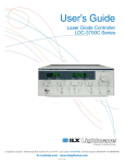
It is also recommended that the connections to the LDC-3916330 Series module
output be made using twisted wire pairs with an earth-grounded shield (see
Figures 2.1 -2.4). We recommend using our CC-303 Shielded Laser Cable which
is a unique twisted-pair cable with braided outer shield designed to provide the
best possible rejection of most transient noise signals. The output terminals of
the instrument are left floating relative to earth ground to suppress AC poweron/power-off transients that may occur through an earth-ground path. If the output
circuit is earth-grounded at some point (such as through the laser package and
mount), the user must be careful to avoid multiple earth grounds in the circuit.
Multiple earth grounds may provide circuit paths that induce spurious currents in
the photodiode feedback circuit and output leads.
Note: Experience indicates that should an inadvertent open circuit occur during laser
operation (while the LASER is ON), your laser may be damaged by a momentary circuit
break-and-remake before the final circuit break. Your new LDC-3916330 Series Module
has circuitry designed to detect open circuits and will shut the output off under most
conditions. However, we recommend that cable connections to the laser be secure enough
that they won't open-circuit, should they be jostled or bumped.
Note: Use appropriately shielded cabling to reduce coupling of potentially laser damaging
transients. Do not "bundle" the current source cables with other cables in your system or
laboratory. See Application Note #3, "Laser Diode Protection Strategies" for more detailed
discussions on connecting to your laser.
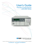
Figures 2.1 - 2.4 show the possible configurations of connecting laser diodes and
photodiodes with the LDC-3916330 Series Laser Diode Controller Modules.
Module
OUTPUT
7
+
6
Bias
+
9
5
P. D.
L. D.
3
Earth Ground
Figure 2.1 Common Laser Cathode - Photodiode Cathode
8
LDC-3916330 Series
OPERATIONS
Connecting to the Laser Current Source
CHAPTER
2
Module
OUTPUT
7
+
6
Bias
+
9
5
P. D.
3
L. D.
Earth Ground
Figure 2.2 Common Laser Cathode - Photodiode Anode
Module
OUTPUT
7
+
Bias
+
6
9
5
P. D.
L. D.
3
Earth Ground
Figure 2.3 Common Laser Anode - Photodiode Cathode
Module
OUTPUT
7
+
6
Bias
+
9
5
P. D.
L. D.
3
Earth Ground
Figure 2.4 Common Laser Anode - Photodiode Anode
09_07
LDC-3916330 Series
9
CHAPTER
2
OPERATIONS
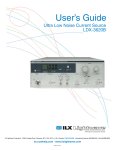
Connecting to the Laser Current Source
Connectors on the rear panel of the LDC-3916330 Series modules provide
laser anode and cathode, photodiode anode and cathode, chassis ground,
interlock and laser forward voltage connections. A pin-out diagram for these
connectors is shown in Figure 2.2. The LDC-3916332 and LDC-3916334
modules are dual current source modules and have two 9-pin connectors, one
for each laser source. The top connector is for the current source called LAS1
while the bottom connector is for the current source called LAS2.
Figure 2.5 Back Panel LD Connector
Interlock Connections
In order for the laser output to be enabled, a short must exist between the
Interlock pins (pins 1 and 2) of the connector. The short can be a direct short
across the pins or a switch to prevent laser operation until the switch is closed. If
a short does not exist between these two pins and you attempt to turn on the LAS
output, an error will be indicated on the display for the respective channel, on any
of the Laser set up pages, or on the status screen; furthermore, the output will be
turned off. The error is E401 if LAS1's interlock is disconnected, and the error is
E501 if LAS2's interlock is disconnected.
The interlock terminals on the LASER connector, pins 1 and 2, must be kept isolated
from all other connections including earth ground.
Four-Wire Voltage Sense
The LDC-3916330 Series Modules have a 4-wire voltage sense feature. The laser
voltage is sensed through a pair of connections (pins 4 and 8) that is separate
from the laser current drive connections (pins 5 and 9). This allows a more
accurate laser voltage reading for the voltage limit feature. All four of these pins
10
LDC-3916330 Series
OPERATIONS
Connecting to the Laser Current Source
CHAPTER
2
(4,5,8,9) must be connected for the module to operate. See Tech Note #TN3916-2
for more information on 4-wire Voltage Sense.
Photodiode Connections
Many laser diode modules contain an internal photodiode that monitors the backfacet emission of the laser. Usually, this photodiode is internally connected to
either the laser anode or cathode.
The photodiode and laser connections to the LDC-3916330 Series Module are
electrically isolated from ground and each other. So, if a 4 pin connection is made
(no common connections) no additional jumpers are required. Figures 2.1 - 2.4
show the recommended connections and shielding for 3-pin lasers (where the
common connection is internal to the device). A 4-pin laser should be connected
with the same shielding as shown in Figure 2.1, but the common connection
(between the photodiode and the laser) is optional.
Grounding Considerations
The LASER outputs of the LDC-3916330 Series Laser Diode Controller Module
are isolated from chassis ground allowing either output terminal to be grounded at
the user's option. Figure 2.1 shows the proper earth-ground shielding for laser
diode/photodiode connections.
09_07
LDC-3916330 Series
11
CHAPTER
2
OPERATIONS
Operating the Laser Current Source from the Front Panel
Operating the Laser Current Source from the Front Panel
The various laser current source control parameters can be set the same for all
channels via the All Chnl menu which is accessed through the MAIN menu.
Alternatively, the laser source control parameters for each individual channel can
be set independently via channel setup menus, which are accessed through the
CHAN menu. You can move between multiple pages of any setup menu by
pushing the up and down arrow soft keys (F3 and F4) while in the setup menu.
Which parameter to adjust can be selected with the (DISPLAY) UP/DOWN
ARROW keys. In general, the selected parameter value can be adjusted with the
numeric keypad, the ADJUST knob, or the (ADJUST) UP/DOWN ARROW keys.
The ENTER key must be pressed within three seconds after entering a numeric
value with the keypad, or the value will revert to the previous value.
The DISPLAY is used to show both the set point and measured value of laser
control parameters such as laser drive current (Iset and Io), laser current limit
(Ilim), laser forward voltage (Vf), forward voltage limit (Vlim), mode of control
(Mode), monitor photodiode current (Ipdset and Ipd), and laser optical power (Plim
and Ppd). It will also display error codes, which relate to LASER operation. Error
codes indicate control errors and are explained below in the section titled
"LASER ERROR INDICATORS". The following sections describe fundamentals of
single channel operation for your LDC-3916330 Series Laser Diode Current
Sources in two operating modes, Constant Current (I) and Constant Power (P).
12
LDC-3916330 Series
OPERATIONS
Operating a Laser in Constant Current (I) Mode
CHAPTER
2
Operating a Laser in Constant Current (I) Mode
Suppose you have an LDC-3916330 Series Module and you want to run the
instrument in Constant Current low bandwidth mode (Ilbw), with a set point of 150
mA, a current limit of 175 mA, and a voltage limit of 6 volts. The Ilbw mode uses a
low-pass filter on the laser drive current output to significantly reduce noise. In this
mode a low bandwidth modulation input may be used via the back panel
MODULATION connector. Follow the instructions below, in the sequence
presented, to program the current source for a single channel.
Entering the Laser Channel Setup Menu
Push the CHAN key to display the single channel menu. From this menu you can
see the measured parameters, enter the LAS1 or LAS2 channel setup menus
(3916332/334 modules) or the LAS setup menu (3916338), or turn the current
sources on and off. Use the (ADJUST) UP/DOWN ARROW keys or the ADJUST
knob to select the desired channel number highlighted at the top of the display.
For the 3916332/334 modules, push the DISPLAY LAS1 soft key (F2) to enter
page 1 of the laser channel setup menu. Push the LAS2 soft key (F4) to program
the second current source in this module.
For the 3916338 module, push the display down arrow soft key (F4) to enter page
1 of the laser channel set up menu.
09_07
LDC-3916330 Series
13
CHAPTER
2
OPERATIONS
Operating a Laser in Constant Current (I) Mode
Setting the Mode of Control
Select the Mode parameter by pushing the (DISPLAY) UP/DOWN ARROW keys
until the Mode parameter is highlighted. Repeatedly pushing the (ADJUST)
UP/DOWN ARROW keys or turning the ADJUST knob will cycle through the
Constant Current low bandwidth (Ilbw), Constant Optical Power (P), Constant
Current high bandwidth (Ihbw), and Photodiode Current (Ipd) control modes. Set
the LDC-3916330 Series Controller Modules in Constant Current low bandwidth
mode by selecting the Ilbw mode.
Setting the Current Limit
Now select the current limit (Ilim) parameter using the (DISPLAY) UP/DOWN
ARROW keys. Adjust the value to 175mA. The current limit protects your laser by
never allowing the laser drive current to exceed the Ilim value independent of the
current set point and the controller mode (Constant Current or Constant Power).
Failure to set and ensure a proper Ilim value could result in laser damage.
14
LDC-3916330 Series
OPERATIONS
Operating a Laser in Constant Current (I) Mode
CHAPTER
2
Setting the Constant Current Value
Next, select the Iset parameter on the setup menu using the (DISPLAY)
UP/DOWN ARROW keys. This parameter sets the laser current source drive
value when in Ilbw or Ihbw modes. Enter 150 mA using the numeric keypad, the
ADJUST knob, or the (ADJUST) UP/DOWN ARROW keys. Push the ENTER key
to store the value in memory within three seconds after entering the value using
the numeric keypad, or it will revert to the old value.
Setting the Voltage Limit
Select the voltage limit (Vlim) parameter and adjust it to 6 volts in the same
manner as described above. The voltage limit also protects your laser by shutting
off the source driver if the laser voltage exceeds the Vlim value. The Vlim value
should be set slightly above the operating voltage of the laser diode to provide
maximum protection.
Note: There is also a laser optical power limit (Plim) safety feature explained in this
manual under the section titled “Operating a Laser in Constant Power (P) Mode”. The laser
optical power limit can be disabled by setting the CalPD value to zero on page 2 of the
laser setup menu.
09_07
LDC-3916330 Series
15
CHAPTER
2
OPERATIONS
Operating a Laser in Constant Current (I) Mode
Enabling the Modulation Input
Change the display to LAS p.3 of the laser setup menu to set the next parameter.
Do this by pushing the DOWN soft key (F4) twice. The Modulation parameter on
this page controls whether the MODULATION connector input is active or not.
Select the Modulation parameter by pressing the (DISPLAY) UP/DOWN ARROW
keys until the Modulation parameter is highlighted. Adjust the value to ON or OFF
as desired with the (ADJUST) UP/DOWN ARROW keys or the ADJUST knob.
Refer to the LDC-3916330 Series Controller Module specifications for modulation
input specifications and limitations.
Turning the Laser Current Source On
Now you are ready to enable the current source output for your laser diode. The
top soft key (F1) on any of the three pages of the LAS setup menu will toggle the
laser current source on and off. You can also turn the current source on and off
with the top soft key (F1) on the CHAN menu. The ON toggle has a two second
delay before the current source is enabled in compliance with safety
requirements.
Each current source can be turned on or off independently as described above, or
you can turn on all the channels at the same time from the All Chnl menu. See the
LDC-3908, LDC-3916 or LDC-3926 Mainframe Instruction Manual for more
information on the all channel operation.
16
LDC-3916330 Series
OPERATIONS
Operating a Laser in Constant Power (P) Mode
CHAPTER
2
Operating a Laser in Constant Power (P) Mode
Suppose you want to operate a 3 mW laser in constant optical power at 1 mW.
The LDC-3916330 Series Controller Modules allow you to operate the instrument
current source drivers in Constant Optical Power (P) mode. In the "P" mode, the
controller drives current to the laser to reach a set power value in mW. The
control loop feedback parameter is monitor photodiode current, which the
controller converts to optical power via a user defined photodiode responsivity
number, CalPD. If laser power changes due to internal or environmental
conditions, the controller will increase/decrease the current to the laser to
maintain the power set point. The following paragraphs detail the instrument
configuration in Constant Power Mode.
Calculating Photodiode Responsivity Values
The photodiode responsivity, CalPD, is used to convert between photodiode
current and optical power of the laser diode. A method to calculate the
responsivity is suggested below.
1
Measure (with a calibrated detector) the output power of the laser.
2
Measure the corresponding monitor photodiode current.
3
Calculate the responsivity (CalPD) by dividing the photodiode current by the optical power
noting the units required are A/mW.
Entering the Laser Channel Setup Menu
To enter the setup menu, push the CHAN key, which displays the channel menu.
Select the correct channel number at the top of the display by pushing the
(ADJUST) UP/DOWN ARROW keys or turning the ADJUST knob. For the
3916332/334 modules, push the DISPLAY LAS soft key (F2) to enter page 1 of
the laser setup menu. (See image above.)
09_07
LDC-3916330 Series
17
CHAPTER
2
OPERATIONS
Operating a Laser in Constant Power (P) Mode
For the 3916338 module, push the display down arrow soft key (F4) to enter page
1 of the laser setup menu. (See image above.)
Selecting the Mode of Control
Select the Mode parameter by pushing the (DISPLAY) UP/DOWN ARROW keys
until the Mode parameter is highlighted. Repeatedly pushing the (ADJUST)
UP/DOWN ARROW keys or turning the ADJUST knob will cycle through the
Constant Current low bandwidth (Ilbw), Constant Optical Power (P), Constant
Current high bandwidth (Ihbw), and Photodiode Current (Ipd) control modes. Set
the LDC-3916330 Series Controller Module in Constant Optical Power mode by
selecting the P mode.
18
LDC-3916330 Series
OPERATIONS
Operating a Laser in Constant Power (P) Mode
CHAPTER
2
Setting the Current Limit
Select the laser current limit (Ilim) parameter by pushing the (DISPLAY)
UP/DOWN ARROW keys until the Ilim value is highlighted with the cursor. Adjust
the current limit value with the numeric keypad, the ADJUST knob, or the
(ADJUST) UP/DOWN ARROW keys. If you use the numeric keypad, you mush
push the ENTER key to store the value in memory within three seconds after
entering the value, or it will revert to the previous value. The current limit protects
your laser by never allowing the laser drive current to exceed the Ilim value
independent of the current set point and the controller mode (Constant Current or
Constant Power).
Failure to set and ensure a proper current limit value could result in laser damage.
Setting the Voltage Limit
Next, select the laser voltage limit (Vlim) parameter using the (DISPLAY)
UP/DOWN ARROW keys. Adjust this value to your desired laser voltage limit. The
voltage limit also protects your laser by shutting off the source driver if the laser
09_07
LDC-3916330 Series
19
CHAPTER
2
OPERATIONS
Operating a Laser in Constant Power (P) Mode
voltage exceeds the Vlim value. The Vlim value should be set slightly above the
operating voltage of the laser diode to provide maximum protection.
Note: Be sure to push the ENTER key within three seconds after using the keypad to
adjust any numeric values in the setup menus; otherwise, the value will revert to the
previous setting.
Setting the Power Limit
Now push the DOWN soft key (F4) to advance to LAS p.2 of the laser setup
menu. Before the laser is enabled, the power limit for the laser under test should
be set. To do this, push the (DISPLAY) UP/DOWN ARROW keys to select the
power limit (Plim) parameter. Adjust this value to your desired laser optical power
limit. The responsivity value (CalPD) must be set to the correct value for the
power limit feature to work properly. This is a software limit only. The LASER
output is normally turned off if this limit is reached.
Adjusting the Constant Power Setting
Use the (DISPLAY) UP/DOWN ARROW keys to select the power (Pset)
parameter, and adjust the value to 1 mW. The Controller Module will divide the
measured photodiode current by the CalPD value to calculate the laser optical
power. The current source will automatically adjust the laser drive current to keep
the calculated laser power at the Pset value.
20
LDC-3916330 Series
OPERATIONS
Operating a Laser in Constant Power (P) Mode
CHAPTER
2
Setting the Responsivity Value (CalPD)
The correct responsivity value (CalPD) must be set for the constant power mode
to operate properly. To do this, select the CalPD parameter, and adjust it to the
correct value. The CalPD units are µA/mW.
A method to calculate the responsivity value (CalPD) is suggested here:
• Measure (with a calibrated detector) the output power of the laser.
• Measure the corresponding monitor photodiode current.
• Calculate the responsivity (CalPD) by dividing the photodiode current by the optical power
noting the units required are µA/mW.
Setting the Photodiode Bias Voltage
Now push the DOWN soft key (F4) to display LAS p.3 of the laser setup menu.
The Bias parameter setting controls whether or not a bias voltage is applied to the
monitor photodiode. Select the Bias parameter and adjust it ON or OFF
depending on whether you want a 5 volt reverse bias on your photodiode or not.
(Many laser diode modules are tested and characterized by the manufacturer with
a 5 volt reverse bias on the photodiode. This bias can decrease the response time
and increase the linearity and/or saturation level of the photodiode.)
09_07
LDC-3916330 Series
21
CHAPTER
2
OPERATIONS
Operating a Laser in Constant Power (P) Mode
Constant Power Mode if CalPD is Unknown
If you do not know the correct photodiode responsivity (CalPD) value, the
LDC-3916330 Series Modules can still drive your laser at a constant light power.
The Constant Photodiode Current (Ipd) mode will control the laser drive current so
the monitor photodiode current remains at a constant set point. To do this, adjust
the Mode to Ipd on LAS p.1 of the laser setup menu, and set the photodiode
current (Ipdset) parameter on the LAS p.2 menu to your desired value. In this
case, you may want to set the power limit (Plim) value high or set CalPD to zero
which will disable the power limit feature.
Turning the Laser Current Source On
Now this channel is configured to operate in Constant Power Mode. The
Controller's laser current source will drive the laser to the Constant Power set
point and maintain closed loop control with the monitor photodiode current
measurement. You can enable this channel now or set all of the other channels
first. The top soft key (F1) on any of the three pages of the LAS setup menu will
toggle the laser current source on and off. You can also turn the current source on
and off with the top soft key (F1) on the channel menu. The ON toggle has a two
second delay before the current source is enabled in compliance with safety
requirements.
Each current source can be turned on or off independently as described above, or
you can turn on all 16 channel sources at the same time from the All Chnl menu.
See the LDC-3908, LDC-3916 or LDC-3926 Mainframe Instruction Manual for
more information on all channel operation.
22
LDC-3916330 Series
OPERATIONS
Conditions Which Will Automatically Shut Off the Laser Output
CHAPTER
2
Conditions Which Will Automatically Shut Off the Laser
Output
When the LASER output is off, an internal short is placed across the LASER
output. The default condition for the current source output is OFF when the
instrument is first powered up. With the laser output enabled, the channel or
status displays should be indicating measured laser current. If the output won't
function or an error code appears, check the conditions shown below or table 2.3
"LASER Error Indicators".
The following conditions will automatically force the laser current source to turn
off:
1
LASER High Power Limit (Plim, E507)
2
LASER High Voltage Limit (Vlim, E503 or E505)
3
LASER ENABLE Interlock (E501)
4
LASER ENABLE Key Lock turned off on the front panel (E501)
5
LASER Open Circuit (E503)
6
TEC High Temperature Limit Condition (E509)
In addition, the LASER Current Limit setting (Ilim) will clip the laser drive current at
the Ilim set point when the signal is being modulated. When the LASER current
limit (Ilim) is reached, an ILIM warning will appear on the CHAN menu display.
The current limit setting is independent of the voltage drop of the device
connected to the LASER output. Furthermore, since the current limit circuitry is
fully independent of the main current control, the current limit can be adjusted
safely, even while the LASER output is active.
The LDC-3916330 Series Modules' response to sensing the various limits can be
controlled via the GPIB interface. Most high limit responses can be set to either
turn off the source or just give a limit warning through the GPIB interface. See the
"LAS:ENAB:OUTOFF" command in Chapter 4 of this manual for more
information.
09_07
LDC-3916330 Series
23
CHAPTER
OPERATIONS
Laser Error Indicators
2
Laser Error Indicators
The LDC-3916330 Series Laser Diode Current Source Controllers indicate
general LASER operational error conditions. When an error occurs, the Error
Indicator Code will appear on the status page, the Chan page, or the LAS setup
pages for the respective current source. Laser error indicator codes are
summarized in Table 2.2. The error indicator code will clear if you exit any page
that it appears on after the error has been corrected. The output drive will shut off
when and laser error code occurs. Error codes that start with “E4” are for the
LAS1 current source. Error codes that start with “E5” are for the LAS2 current
source.
Table 2.2 LASER Error Indicators
Error Code
LDC-3916332/334
LDC-3916338
LAS1
LAS2
LAS
E401
E501
E501
24
Description
Interlock
E403
E503
E503
E404
E504
E504
E405
E505
E505
Voltage Limit
Warning
E407
E507
E507
E408
E508
E508
Output Power
Limit
TEC is off
E409
E509
E509
TEC
Temperature
Limit
E410
E520
E520
E411
E511
E511
E429
E529
E529
E435
E535
E535
Tolerance
Event
Hardware
error
Output off
when
controller
detects on
Mode changed
while output
enabled
LDC-3916330 Series
Voltage Limit
or Open
Circuit
Current Limit
Probable Cause
Interlock pins not connected properly or LASER
ENABLE key lock turned off on front panel
The laser current source pins are open, or some
condition caused the laser voltage to exceed the
voltage limit setting.
The current limit was reached. This condition
will cause an error indicator code and shut down
the current source only when enabled through
the GPIB interface; otherwise, a current limit will
only limit the drive current at the limit value and
indicate ILIM on the display.
The voltage on the laser current source is
approaching the limit value. This condition will
cause an error indicator code and shut down the
current source only when enabled through the
GPIB interface.
Software calculated optical output power limit
was detected
A TEC source, such as a 3916558 which has
been programmed to control this channel’s laser
module has turned off. This condition will shut
down the laser source only when enabled
through the GPIB interface.
A TEC source, such as a 3916558 which has
been programmed to control this channel’s laser
module has turned off due to a temperature limit
condition. This condition will shut down the
laser source only when enabled through the
GPIB interface.
Out of tolerance status forces LAS output off.
Firmware has detected a hardware error.
The laser source is off without hardware or
firmware indication.
Operating mode of the module was changed
while the laser output enabled.
CHAPTER
3
REMOTE OPERATIONS
Everything you can do from the front panel can also be done remotely and in
some cases with more flexibility. For example, in remote mode, you can enable or
disable conditions that will cause the laser current source or the TEC controller to
automatically shut off. The following sections show you the fundamentals of
operating your LDC-3916330 Series module remotely through the GPIB and
RS-232 interfaces.
Remote Configuration
Refer to the LDC-3916 Instruction Manual Chapter 3, "Operating in Remote
Control" for information concerning setup of GPIB or RS-232 remote
communications. That section also describes the use of IEEE 488.2 common
commands, LDC-3916 mainframe commands, and syntax.
LDC-3916330 Series Laser Diode Controller Command Set
The LDC-3916330 Series module utilizes its own module-specific commands, as
well as the commands for the LDC-3916 mainframe (see LDC-3916 User’s
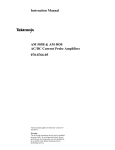
Manual Chapter 3 “Operating in Remote Control”). Figure 3.1 shows all of the
commands which are usable by the LDC-3916 in conjunction with the
LDC-3916330 Series modules.
LDC-3916330 Series
25
CHAPTER
3
REMOTE OPERATIONS
LDC-3916330 Series Laser Diode Controller Command Set
(root)
:LASER1 (or :LASER2)
*CAL?
*CLS
*ESE
*ESE?
*ESR>
*IDN?
*OPC
*OPC?
*PSC
*PSC?
*PUD
*PUD?
*RCL
*RST
*SAV
*SRE
*SRE?
*STB?
*TST?
*WAI
ALLCOND?
ALLEVE?
BEEP
BEEP?
CHAN
CHAN?
CHECKSUM?
DELAY
ERR?
MENU
MES
MES?
RAD
RAD?
SECURE
TERM
TERM>
TIME?
TIMER?
MODERR?
MODIDN?
MODPUD
MODPUD?
STATMENU:LINEn:?
STATMENU:LINEn:LDI
STATMENU:LINEn:PPD
STATMENU:LINEn:IPD
STATMENU:LINEn:VF
( n = 1 or 2 )
:BIAS
:BIAS?
:CALPD
:CALPD?
:COND?
:DEC
:EVE?
:INC
:LDI
:LDI?
:LDV
:LDV?
:MDI
:MDI?
:MDP
:MDP?
:MODE?
:MOD
:MOD?
:OUT
:OUT?
:STEP
:STEP?
:SYNCLDI?
:SYNCLDV?
:SYNCMDI?
:SYNCMDP
:TOL
:TOL?
:ENAB
:LIM
:MODE :SET
:CAL
:COND
:COND?
:EVE
:EVE?
:OUTOFF
:OUTOFF?
:I
:I?
:MDP
:MDP?
:V
:V?
:IHBW :LDI?
:ILBW :MDI?
:MDP :MDP?
:MDI
:ABORT
:DEFAULT
:LDI
:LDV
:MEAS
:MDI
:STAT?
:VALUE?
Figure 3.1 LDC-3916 and LDC-3916330 Series Command Path Structure
26
LDC-3916330 Series
REMOTE OPERATIONS
LDC-3916330 Series Laser Diode Controller Often Used Commands
CHAPTER
3
LDC-3916330 Series Laser Diode Controller Often Used
Commands
Table 3.1 LDC-3916330 Series Often Used Commands
NAME
CHAN
ERR?
PARAMETERS
1
NONE
MODERR?
NONE
LASERn:
LASERn:CALPD
1
LASERn:LDI
LASERn:LDI?
LASERn:LDV?
LASERn:LIM:I
LASERn:LIM:MDP
LASERn:LIM:V
LASERn:MDI?
LASERn:MDP
LASERn:MDP?
LASERn:MODE:IHBW
LASERn:MODE:ILBW
LASERn:MODE:MDI
LASERn:MODE:MDP
LASERn:OUT
LASERn:OUT?
1
NONE
NONE
1
1
1
1
1
NONE
NONE
NONE
NONE
NONE
1
NONE
FUNCTION
Sets the channel (or ALL channels) for further commands.
Returns “Mainframe” errors generated since the last query,
followed by a binary representation of existing module errors.
Returns module errors generated since the last error query (to
that module).
Sets the monitor photodiode responsivity for Power mode use1.
Sets the constant current source set point.
Returns the measured output current.
Returns the measured laser voltage.
Sets the current source limit.
Sets the constant optical power (from monitor PD) limit.
Sets the current source voltage limit.
Returns the measured monitor PD current.
Sets the constant optical power set point.
Returns the measured optical power.
Sets the mode to constant current, high bandwidth mode.
Sets the mode to constant current low bandwidth mode.
Sets the mode to constant photodiode current mode.
Sets the mode to constant optical power mode.
Used to turn the current source output on or off.
Returns the current source output status.
Command Timing and Completion
All commands for the LDC-3916330 Series modules are sequential, except for the
“LAS:OUT ON”, “LAS:INC”, and “LAS:DEC” commands. The “LAS:OUT ON”
command is overlapped to allow the user to abort it with the “LAS:OUT OFF”
command during a two second interval after the output is told to be on. The
“LAS:INC” and “LAS:DEC” commands are overlapped to allow the user to monitor
the other functions while in an automatic ramping mode.
For more information on the use of operation complete commands, such as *WAI
and *OPC, refer to the LDC-3916 User’s Manual, Chapter 3.
09_07
LDC-3916330 Series
27
CHAPTER
3
REMOTE OPERATIONS
Status Reporting
Status Reporting
Refer to the LDC-3916 Laser Diode Controller Instruction Manual, Chapter 3
"Operating in Remote Control" for information on standard status structures,
mainframe-related commands, and for understanding the Operation Complete
definition.
The following sections discuss the LDC-3916330 Series module-dependent
aspects of the status reporting, including the "OUTOFF" commands and queries.
The Output Off Register section also contains information on specifying some of
the conditions that will force the laser current source and/or TEC output off.
Status Registers
The LDC-3916330 Series modules provide status registers which are summarized
in the LDC-3916 mainframe. These summaries are accessed by the
"ALLCOND?" and "ALLEVE?" remote queries. Refer to the LDC-3916 Instruction
Manual for details on remote status reporting.
Each channel of the LDC-3916 may contribute to the "ALLCOND" and "ALLEVE"
registers. For the LDC-3916330 Series modules, the enabled conditions of both
the LAS and TEC functions are logically ORed, and the summary is passed to the
appropriate bit of the ALLCOND register (see Figure 3.2). Likewise, the enabled
events of both the LAS and TEC functions are logically ORed, and the summary is
passed to the appropriate bit of the ALLEVE register (see Figure 3.3).
For example, you may wish to have the LDC-3916 create an interrupt to the host
PC in the event of the TEC output shutting off. To do this you would first enable
the event with the "TEC:ENAB:EVE 1024" command. This would allow the event
to be passed to the ALLEVE register on the 3916 mainframe. The ALLEVE status
can be read by the "ALLEVE?" query and the summary can be monitored with the
"*STB?" query. To generate the SRQ (interrupt) for our example, you must also
set the Service Request Enable Register, e.g. "*SRE 1", to allow the ALLEVE
summary to generate the interrupt. See the LDC-3916 Instruction Manual,
Chapter 3, for details on status structures.
Note: When the laser voltage reaches the voltage limit setting (LAS:LIM:V), the hardware
will always shut the laser off. The “Laser Voltage Limit” referred to in the Event, Condition,
and Output Off Registers occurs when the voltage is about 0.25 volts less than the voltage
limit setting. This feature can be used for a warning before the actual voltage limit is
reached.
28
LDC-3916330 Series
REMOTE OPERATIONS
Status Reporting
CHAPTER
3
LASER1 Condition Status Register
LASER1:COND?
15 14 13 12 11 10 9 8 7 6 5 4 3 2 1 0
bit-wise
LOGICAL AND
LOGICAL OR
15 14 13 12 11 10 9 8 7 6 5 4 3 2 1 0
LASER1 Condition Status Enable Register
LASER1:ENABle:COND <nrf>
LASER1:ENABle:COND?
To ALLCOND
Register
LOGICAL OR
LASER2 Condition Status Register
LASER2:COND?
15 14 13 12 11 10 9 8 7 6 5 4 3 2 1 0
bit-wise
LOGICAL AND
LOGICAL OR
15 14 13 12 11 10 9 8 7 6 5 4 3 2 1 0
LASER2 Condition Status Enable Register
LASER2:ENABle:COND <nrf>
LASER2:ENABle:COND?
LASER1 Condition Bit Reference
0 - Current Limit
1 - Voltage Limit
2 - n/a
3 - Power Limit
4 - Interlock Error
5 - n/a
6 - n/a
7 - Open Circuit
8 - Output Shorted
9 – In Tolerance
10 - Output On
11 - n/a
12 - n/a
13 - n/a
14 - n/a
15 - n/a
LASER2 Condition Bit Reference
0 - Current Limit
1 - Voltage Limit
2 - n/a
3 - Power Limit
4 - Interlock Error
5 - n/a
6 - n/a
7 - Open Circuit
8 – Output Shorted
9 – In Tolerance
10 - Output On
11 - n/a
12 - n/a
13 - n/a
14 - n/a
15 - n/a
Figure 3.2 LDC-3916330 Series Condition Registers
09_07
LDC-3916330 Series
29
CHAPTER
3
REMOTE OPERATIONS
Status Reporting
LASER1 Event Status Register
LASER1:EVEnt?
15 14 13 12 11 10 9 8 7 6 5 4 3 2 1 0
bit-wise
LOGICAL AND
LOGICAL OR
15 14 13 12 11 10 9 8 7 6 5 4 3 2 1 0
LASER1 Event Status Enable Register
LASER1:ENABle:EVEnt <nrf>
LASER1:ENABle:EVEnt?
To ALLEVE
Register
LOGICAL OR
LASER2 Event Status Register
LASER2:EVEnt?
15 14 13 12 11 10 9 8 7 6 5 4 3 2 1 0
bit-wise
LOGICAL AND
LOGICAL OR
15 14 13 12 11 10 9 8 7 6 5 4 3 2 1 0
LASER2 Event Status Enable Register
LASER2:ENABle:EVEnt <nrf>
LASER2:ENABle:EVEnt?
LASER1 Event Bit Reference
0 - Current Limit
1 - Voltage Limit
2 - n/a
3 - Power Limit
4 - Interlock Error
5 - n/a
6 - n/a
7 - Open Circuit
8 - Output Shorted
9 – Tolerance Change
10 - Output On
11 - n/a
12 - n/a
13 - n/a
14 - n/a
15 - n/a
LASER2 Event Bit Reference
0 - Current Limit
1 - Voltage Limit
2 - n/a
3 - Power Limit
4 - Interlock Error
5 - n/a
6 - n/a
7 - Open Circuit
Figure 3.3 LDC-3916330 Series Event Registers
30
LDC-3916330 Series
8 - Output Shorted
9 – Tolerance Change
10 - Output On
11 - n/a
12 - n/a
13 - n/a
14 - n/a
15 - n/a
REMOTE OPERATIONS
Status Reporting
CHAPTER
3
Output Off Registers
The Output Off Enable Registers allow you to determine which conditions and
events in the TEC and LASER controllers can cause their outputs to be turned off.
These registers are configured in a manner which is similar to the status reporting
registers. However, their values are not reported in the Status Byte Register.
These registers are used by the firmware to control the output enable for that
function (LASER or TEC). The events and conditions which may be set to cause
the TEC and LASER outputs to be turned off are shown in Figures 3.4 and 3.5.
The default settings for these registers for an LDC-3916330 Series module are
shown in Table 3.2. The registers take on these values at power-up, as the result
of a *RST command, or when you choose "Default" from the Save/Recall menu.
These settings are not affected by the *PSC (Power-On Status Clear) command.
Table 3.2 LDC-3916330 Series Default Settings for Output Off Registers
TEC Output Off Register
LASER Output Off Register
Bit
0
1
2
3
4
5
6
7
8
9
10
11
12
13
14
15
Name
Current Limit
Voltage Limit
N/A
Power Limit
N/A
N/A
N/A
N/A (see Note 1 below)
N/A
Out of Tolerance
TEC Output Off
TEC High Temp Limit
N/A
N/A
N/A
N/A
State
Disabled
Disabled
Enabled
Disabled
Disabled
Enabled
Bit
0
1
2
3
4
5
6
7
8
9
10
11
12
13
14
15
Name
Current Limit
Voltage Limit
N/A
High Temperature Limit
N/A
N/A
Sensor Open
TE Module Open Circuit
Sensor Type changed
Out of Tolerance
Sensor Shorted
N/A
N/A
N/A
N/A
N/A
State
Disabled
Disabled
Enabled
Enabled
Enabled
Enabled
Disabled
Enabled
Note: Bit 7 is Laser Open Circuit in the Laser Condition and Event registers. It is not
available to disable in the Output Off Enable register because it is always active in the
hardware.
09_07
LDC-3916330 Series
31
CHAPTER
REMOTE OPERATIONS
Status Reporting
3
LASERn Output Off Register
15 14 13 12 11 10 9 8 7 6 5 4 3 2 1 0
Turn
Output
Off
bit-wise
LOGICAL AND
LOGICAL OR
15 14 13 12 11 10 9 8 7 6 5 4 3 2 1 0
LASERn Output Off Enable Register
LASERn:ENABle:OUTOFF <nrf>
LASERn:ENABle:OUTOFF?
LASERn Output Off Bit Reference
0 - Current Limit
1 - Voltage Limit
2 - n/a
3 - Power Limit
4 - n/a
5 - n/a
6 - n/a
7 - n/a
8 - n/a
9 - Out of Tolerance
10 - n/a
11 - n/a
12 - n/a
13 - n/a
14 - n/a
15 - n/a
Figure 3.4 LDC-3916330 Series Laser Diode Controller LASER Output Off Register
32
LDC-3916330 Series
REMOTE OPERATIONS
Error Messages
CHAPTER
3
Error Messages
This section contains descriptions of the errors which are specific to the
LDC-3916330 Series modules. These are the error codes that are returned from
the "MODERR?" query. Refer to the LDC-3916 Laser Diode Controller Instruction
Manual, Chapter 3, for a list of LDC-3916 mainframe error codes and descriptions
(the codes returned from the "ERR?" query).
During remote operation, the recommended method for error testing is as follows.
First read the system errors and module error summary with the "ERR?" query.
This allows you to error check the LDC-3916 as a whole. If any module errors are
present, the corresponding bit of the error summary will be set. For example, if
the "ERR?" query returns "0,0001000000100000" there are errors on channels 13
and 6. Then read the module errors using the "MODERR?" query. For example,
"Chan 13;Moderr?" and "Chan 6;Moderr?" queries could be sent. For more
information on LDC-3916 mainframe errors, refer to Chapter 3 of the LDC-3916
Instruction Manual.
Table 3.3 LDC-3916330 Series Error Message Codes
09_07
Error Code
Explanation
E-103
E-104
E-105
E-106
E-114
E-123
E-126
Length of arbitrary block is different from expected length.
Parameter is an undefined numeric type.
Parameter has an invalid exponent.
A digit was expected in the parameter but was not found.
Specified arbitrary block length is invalid.
Command is not found.
Wrong number of parameters for command.
E-201
E-202
E-203
E-204
E-205
E-206
E-207
E-208
E-209
E-210
E-211
E-212
E-214
E-222
E-223
E-226
Parameter value out of range.
Error in conversion of parameter type.
Command is a "secure" command, but secure commands are disabled.
Suffix is invalid.
Expected Boolean parameter is invalid.
Error in conversion to signed 16-bit integer.
Error in conversion to unsigned 16-bit integer.
Error in conversion to signed 32-bit integer.
Error in conversion to unsigned 32-bit integer.
Error in conversion to floating-point number.
Error in conversion to character pointer.
Error in conversion to byte pointer.
Response is too long to output.
Set value is over range.
Set value is under range.
Error in arbitrary block specification.
LDC-3916330 Series
33
CHAPTER
34
3
REMOTE OPERATIONS
Error Messages
Error Code
Explanation
E-401
E-403
E-404
E-405
E-407
E-408
E-409
E-410
E-411
E-429
E-435
Interlock Open forces Laser 1 output off.
Laser 1 Voltage Limit forces output off. “Open Circuit” error.
Laser 1 Current Limit forces output off.
Laser 1 Voltage Limit forces output off.
Laser 1 Monitor Diode Power Limit forces output off.
External TEC Output Off Status forces LAS1 output off.
External TEC Temperature Limit forces LAS1 output off.
Out of Tolerance status forced LAS1 output off.
Laser 1 Hardware Error forces output off. (e.g. low power line voltage).
Laser 1 Output is off, but Laser 1 Status thought it was on.
Laser 1 Mode changed while output on.
E-501
E-503
E-504
E-505
E-507
E-508
E-509
E-510
E-511
E-529
E-535
Interlock Open forces Laser 2 output off.
Laser 2 Voltage limit forces output off. “Open Circuit” error.
Laser 2 Current Limit forces output off.
Laser 2 Voltage Limit forces output off.
Laser 2 Monitor Diode Power Limit forces output off.
External TEC Output Off Status forces LAS2 output off.
External TEC Temperature Limit forces LAS2 output off.
Out of Tolerance status forced LAS2 output off.
Laser 2 Hardware Error forces output off. (e.g. low power line voltage).
Laser 2 Output is off, but Laser 2 status thought it was on.
Laser 2 Mode changed while output on.
E-601
E-602
E-620
E-621
E-622
Internal error: recalled bin has incorrect checksum. (Settings do not match bin).
Internal error: task synchronization error.
Internal error: resource unavailable.
Internal error: message undeliverable to task.
Internal error: could not send message to mainframe.
E-710
E-711
E-712
E-713
E-714
Internal error: AC power low error detected
Internal error: AC power low error detected
Internal error: Over-temperature error detected on internal sensor
Internal error: Power brown-out error detected
Internal error: Writing to display
E-802
Calibration error: measurement entered before calibration was ready.
LDC-3916330 Series
CHAPTER
4
COMMAND REFERENCE
This chapter is a guide to all of the device-dependent commands for the
LDC-3916330 Series Dual LASER Diode Controller module. The first part
contains an overview of the remote commands used by the LDC-3916330 Series.
The second part contains all of the LDC-3916330 Series commands in
alphabetical order.
Table 4.1 lists the commands for the LDC-3916330 Series modules. It uses the
nomenclature “LASER” in places to indicate that a command can be sent either to
the LASER1 current source or to the LASER2 current source. To send a
command to LASER1, replace “LASERn” with “LASER1”; “LASER2” will cause a
command to go to LASER2.
LDC-3916330 Series
35
CHAPTER
COMMAND REFERENCE
4
Table 4.1 GPIB Command Summary Reference List
36
Name
Parameters
Function
LAS:BIAS
1
Enables or disables the -5 volt photodiode bias
LAS:BIAS?
NONE
Returns the status of the photodiode bias control
LAS:CALPD
1
Used to set the CAL PD (monitor responsivity) constant
LAS:CALPD?
NONE
Returns the CAL PD (monitor responsivity) constant
LAS:CAL:ABORT
NONE
Aborts a calibration
LAS:CAL:DEFAULT
NONE
Restores all calibration values to their defaults
LAS:CAL:LDI
NONE
Enters the LASER current calibration mode
LAS:CAL:LDV
NONE
Enters the LASER voltage calibration mode
LAS:CAL:MDI
NONE
Enters the monitor photodiode current calibration mode
LAS:CAL:MEAS
1
Enters a calibration value
LAS:CAL:STAT?
NONE
Returns a value which represents the calibration status
LAS:CAL:VALUE?
1
Used for factory calibration testing only
LAS:COND?
NONE
Returns the value of the LASER condition register
LAS:DEC
2
Decreases the LASER set point value by one or more steps with
user-programmable delay between steps
LAS:ENAB:COND
1
Sets the enable register for LASER conditions
LAS:ENAB:COND?
NONE
Returns the value of the LAS conditions enable register
LAS:ENAB:EVE
1
Sets the enable register for LAS events
LAS:ENAB:EVE?
NONE
Returns the value of the LAS event enable register
LAS:ENAB:OUTOFF
1
Sets the enable register for LAS conditions which turn the LAS
output off
LAS:ENAB:OUTOFF?
NONE
Returns the value of the LAS outoff enable register
LAS:EVE?
NONE
Returns the value of the LAS event register
LAS:LDI
1
Sets the LASER constant current source set point value
LAS:LDI?
NONE
Returns the constant current source measured value
LAS:INC
2
Increases the LASER set point value by one or more steps with
user-programmable delay between steps
LAS:LDV?
NONE
Returns the measured LASER voltage value
LAS:LIM:I
1
Sets the LASER current source limit
LAS:LIM:I?
NONE
Returns the LASER current source limit
LAS:LIM:MDP
1
Sets the constant optical power (from monitor PD) limit value
LAS:LIM:MDP?
NONE
Returns the optical power (from monitor PD) limit value
LAS:LIM:V
1
Sets the LASER compliance voltage limit value
LAS:LIM:V?
NONE
Returns the LASER compliance voltage limit value
LAS:MDI
1
Sets the monitor current set point
LAS:MDI?
NONE
Returns the monitor PD current measured value
LAS:MDP
1
Sets the constant optical power set point
LAS:MDP?
NONE
Returns the actual monitor PD power value
LDC-3916330 Series
COMMAND REFERENCE
4
CHAPTER
Table 4.1 GPIB Command Summary Reference List
09_07
Name
Parameters
Function
LAS:MODE?
NONE
Returns the mode, I (current), IHBW (high bandwidth), P (optical
power) or MDI (constant monitor current)
LAS:MODE:IHBW
NONE
Sets the mode to constant current, high bandwidth.
LAS:MODE:ILBW
NONE
Sets the mode to constant current low bandwidth mode
LAS:MODE:MDP
NONE
Sets the mode to constant optical power mode.
LAS:MOD
1
Enables or disables the channel’s modulation output
LAS:MOD?
NONE
Returns the status of the channel’s modulation output
LAS:OUT
1
Enables/disables the current source output
LAS:OUT?
NONE
Returns the current source output status
LAS:SET:LDI?
NONE
Returns the LASER constant I (current) set point
LAS:SET:MDI?
NONE
Returns the LASER constant optical power set point
LAS:SET:MDP?
NONE
Returns the constant P (optical power) set point
LAS:STEP
1
Sets the LASER set point step value
LAS:STEP?
NONE
Returns the LASER set point step value
LAS:SYNCLDI?
NONE
Synchronized measurement; returns the LASER current in mA
LAS:SYNCLDV?
NONE
Synchronized measurement; returns the LASER voltage in volts
LAS:SYNCMDI?
NONE
Synchronized measurement; returns the monitor photodiode
current in µA
LAS:SYNCMDP?
NONE
Synchronized measurement; returns the optical power
LAS:TOL
2
Sets the LASER set point tolerance value and time period value
LAS:TOL?
NONE
Returns the LASER set point tolerance value and time period
value
MODERR?
NONE
Returns the error codes (up to 10) from the module
MODIDN?
NONE
Returns identification data from the module
MODPUD
1
Used at factory to set calibration information
MODPUD?
NONE
Returns factory set calibration information
STATMENU:LINEn?
NONE
Returns the name of the measurement that is displayed on line n
of the status menu (n can be either 1 or 2)
STATMENU:LINEn:LDI
NONE
Sets line n of the status menu to display LASER current
STATMENU:LINEn:VF
NONE
Sets line n of the status menu to display LASER forward voltage
STATMENU:LINEn:IPD
NONE
Sets line n of the status menu to display photodiode current
STATMENU:LINEn:PPD
NONE
Sets line n of the status menu to display optical power
LDC-3916330 Series
37
CHAPTER
4
COMMAND REFERENCE
LDC-3916330 Series Device-Dependent Command Reference
LDC-3916330 Series Device-Dependent Command
Reference
This section contains all of the device-dependent commands for the
LDC-3916330 Series Laser Current Source Modules, listed in alphabetical order.
Sub-sections for each path are presented, listing the commands which are legal
for that path. See Chapter 3, Figure 3.1, for command path tree structure.
The following pages contain a reference for the device-dependent commands.
Contained is useful information for the remote operation of the modules. The
pages also contain the commands for only the LASERn current source. The
commands for the LASERn are identical; merely replace “LASER1” with
“LASER2”.
Note: For 3916338 modules, the n in LASERn is not required.
LASERn:
COMMON
DEVICE DEPENDENT
FRONT PANEL
The LASERn: command path is used to get to the LDC-3916330 Series Laser Diode
Current Source’s laser current source commands. The following command paths may be
reached from the LASER: command path.
LASERn:CAL:
LASERn:ENABle:
LASERn:LIMit:
LASERn:MODE:
LASERn:SET:
The following commands may be reach directly from the LASER1: command path.
LASERn:BIAS
LASERn:BIAS?
LASERn:CALPD
LASERn:CALPD?
LASERn:COND?
LASERn:DEC
LASERn:EVEnt?
LASERn:INC
LASERn:LDI
LASERn:LDI?
38
LDC-3916330 Series
LASERn:LDV?
LASERn:MDI
LASERn:MDI?
LASERn:MDP
LASERn:MDP?
LASERn:MODE?
LASERn:MODulation
LASERn:MODulation?
LASERn:OUTput
LASERn:OUTput?
LASERn:STEP
LASERn:STEP?
LASERn:SYNCLDI?
LASERn:SYNCLDV?
LASERn:SYNCMDI?
LASERn:SYNCMDP?
LASERn:TOL
LASERn:TOL?
COMMAND REFERENCE
LDC-3916330 Series Device-Dependent Command Reference
LASERn:BIAS
4
CHAPTER
COMMON
DEVICE DEPENDENT
FRONT PANEL
The LASERn:BIAS command turns the selected channel’s laser photodiode bias on or
off.
:
Parameters
Notes
Examples
LASERn
:
BIAS
<white
space>
<nrf
value>
An <nrf value>; 1 = on, 0 = off
When the BIAS is on, a bias of -5 volts is placed across the photodiode terminals.
“LASER1:BIAS ON” - action: sets Laser1 photodiode bias output on.
“LASER:BIAS ON” - action: sets the laser photodiode bias on (LDC-3916338 only).
LASERn:BIAS?
COMMON
DEVICE DEPENDENT
FRONT PANEL
The LASERn:BIAS? query returns the status of the selected module’s photodiode bias
selection.
:
Parameters
Notes
Examples
09_07
LASERn
:
BIAS
?
None. The response is an <nrf value>.
Photodiode bias is turned off when a *RST command is issued.
“Laser1:BIAS?” - response: 0, means that the selected module’s Laser1 photodiode bias
is off.
LDC-3916330 Series
39
CHAPTER
4
COMMAND REFERENCE
LDC-3916330 Series Device-Dependent Command Reference
LASERn:CALPD
COMMON
DEVICE DEPENDENT
FRONT PANEL
The LASERn:CALPD command sets the selected module’s laser photodiode feedback
responsivity (the CAL PD parameter)
:
Parameters
Notes
Examples
LASERn
:
CALPD
<white
space>
<nrf
value>
An <nrf value>, in microamps/milliwatt (µA/MW).
The module calculates optical power by dividing the monitor feedback current by its
CALPD value. Photodiode (PD) responsivity is frequently provided by manufacturers of
packaged lasers with built-in power monitors, and is typically called “Monitor Detector
Responsivity.” The monitor produces a current when the laser illuminates it, and this
current will increase with increasing laser optical power. Manufacturers of laser modules
with integrated monitors may specify the responsivity of the monitor in terms of the laser
optical power and the resulting monitor current. Fox example, a responsivity may be
specified as 5 µA/mW, meaning that to produce a monitor current or 5 µA, the laser
optical power must be 1 mW. Typically, the specified responsivity is entered into the
current source as CalPD, using the LASERn:CALPD command.
If this parameter is set to 0, the module will not calculate the optical power. It will display
“-----” on the front panel, and GPIB queries of the optical power, using the
“LASERn:MDP?” query, will return -1.0.
“LASER1:CALPD 0” - action: sets the CAL PD parameter to 0.
“Laser1:Calpd 10.0” - action: sets the CAL PD parameter to 10.0 microamp/milliwatt.
A photodiode feedback current of 10 µA will cause the measured optical power to be
1 milliwatt.
LASERn:CALPD?
COMMON
DEVICE DEPENDENT
FRONT PANEL
The LASERn:CALPD? query returns the value of the selected module’s laser photodiode
feedback responsivity (CalPD parameter) setting.
:
Parameters
Notes
Examples
40
LDC-3916330 Series
LASERn
:
CALPD
?
None. The response is an <nrf value>.
If this value is 0, the front panel Ppd will display “----”, and measured optical power (read
with GPIB using the “Laser1:mdp?” query) will be -1.0.
"LASER1:CALPD?” - response: 1.1, means the selected module’s Laser1 CalPD is set to
1.10 µA/mW: a photodiode feedback current of 2.2 µA represents 2 mW of optical power.
COMMAND REFERENCE
LDC-3916330 Series Device-Dependent Command Reference
LASERn:CAL:
CHAPTER
4
COMMON
DEVICE DEPENDENT
FRONT PANEL
The LASERn:CAL: command path is used to get to the selected module’s laser
calibration commands.
The following commands may be reached directly from the LASER:CAL: command path.
LASERn:CAL:ABORT LASERn:CAL:DEFAULT
LASERn:CAL:LDV
LASERn:CAL:MDI
LASERn:CAL:STATUS? LASERn:CAL:VALUE?
LASERn:CAL:LDI
LASERn:CAL:MEAS
LASERn:CAL:ABORT
COMMON
DEVICE DEPENDENT
FRONT PANEL
The LASERn:CAL:ABORT command is used to exit the selected module’s laser
calibration procedure without changing the calibration values.
:
Parameters
Notes
Examples
09_07
LASERn
:
CAL
:
ABORT
None.
If this command is issued while the LDC-3916330 Series Dual Laser Diode Current
Source is in a laser calibration, the calibration will be terminated and the module will
operate with the same calibration values as before the calibration mode was started.
This command is intended for use after a false or invalid calibration is entered, or to exit
calibration mode before any values have been entered.
“Laser1:CAL:ABORT” - action: module exits calibration mode.
LDC-3916330 Series
41
CHAPTER
4
COMMAND REFERENCE
LDC-3916330 Series Device-Dependent Command Reference
LASERn:CAL:DEFAULT
COMMON
DEVICE DEPENDENT
FRONT PANEL
The LASERn:CAL:DEFAULT command sets all of the selected module’s laser calibration
constants to default values.
:
Parameters
Notes
Examples
LASERn
:
CAL
:
DEFAULT
None.
This command should only be used in the case in which the calibration has become
corrupted and circumstances make calibration impossible. Measurements and setpoints
on the laser current source are not guaranteed to meet accuracy specifications after this
command is issued. Accuracy will remain unspecified until calibration is performed on
the module.
“Laser1:CAL:Default” - action: the selected module sets all of its Laser1 calibration
constants to default values.
LASERn:CAL:LDI
COMMON
DEVICE DEPENDENT
FRONT PANEL
The LASERn:CAL:LDI command is used to initiate the calibration procedure for the
selected module’s laser current setpoint, measurement, and current limit.
:
Parameters
Notes
Examples
42
LDC-3916330 Series
LASERn
:
CAL
:
LDI
None.
Both low and high bandwidth modes, along with current limit, are calibrated during this
procedure. See the Service Reference portion of this manual for complete calibration
instructions.
"Laser1:CAL:LdI" -action: the selected module enters calibration mode for Laser1
current.
COMMAND REFERENCE
LDC-3916330 Series Device-Dependent Command Reference
LASERn:CAL:LDV
4
CHAPTER
COMMON
DEVICE DEPENDENT
FRONT PANEL
The LASERn:CAL:LDV command is used to initiate the calibration procedure for the
selected module’s laser voltage measurement.
:
Parameters
Notes
Examples
LASERn
:
CAL
:
LDV
None.
See the Service Reference portion of this manual for complete calibration instructions.
"Laser1:CAL:Ldv" -action: the selected module enters calibration mode for Laser1
voltage measurement.
LASERn:CAL:MDI
COMMON
DEVICE DEPENDENT
FRONT PANEL
The LASERn:CAL:MDI command is used to enter the photodiode current calibration
mode.
:
Parameters
Notes
Examples
09_07
LASERn
:
CAL
:
MDI
None.
See the Service Reference portion of this manual for complete calibration instructions.
"Laser1:CAL:MDI" -action: the selected module enters the Laser1 photodiode current
calibration mode.
LDC-3916330 Series
43
CHAPTER
4
COMMAND REFERENCE
LDC-3916330 Series Device-Dependent Command Reference
LASERn:CAL:MEAS
COMMON
DEVICE DEPENDENT
FRONT PANEL
The LASERn:CAL:MEAS command is used to enter measured values during the
selected module’s laser calibration procedure.
:
LASERn
Parameters
Notes
Examples
:
:
CAL
<white
space>
MEAS
<nrf
value>
An <nrf value> which represents the measured value expected for the present Laser1
calibration state.
See the Service Reference portion of this manual for compete calibration instructions.
"Laser1:CAL:MEAS 4.95” - action: the module uses the value 4.95 for the required
measurement value.
LASERn:CAL:STATus?
COMMON
DEVICE DEPENDENT
FRONT PANEL
The LASERn:CAL:STATus? query is to determine whether the unit is ready for a
calibration value and whether it is in a laser calibration mode.
:
Parameters
Notes
Examples
44
LDC-3916330 Series
LASERn
:
CAL
:
STAT
?
None. The response will be an <nrf value>; 0 = not ready for measurement; 1 = ready for
measurement; 2 = calibration completed; 3 = calibration aborted
If the calibration is aborted, the status value will remain “3” until the calibration is started
again.
"LASER1:CAL:STAT?” - response: 1, means the module is ready for a calibration
measurement to be entered using the “LASER1:CAL:MEAS” command.
“LASER1:CAL:STAT?” - response: 2, means the module has completed calibration.
“LAser1:Cal:Stat?” - response: 0, means the module is not yet ready for the LASER1
calibration measurement value to be entered.
COMMAND REFERENCE
LDC-3916330 Series Device-Dependent Command Reference
LASERn:COND?
CHAPTER
4
COMMON
DEVICE DEPENDENT
FRONT PANEL
The LASERn:COND? query returns the contents of the selected module’s laser condition
status register.
:
Parameters
Notes
Examples
09_07
LASERn
:
COND
?
None. The response is the sum of the following:
1 - Current Limit
256 - Output is Shorted
2 - Voltage Limit
512 - Output in Tolerance
4 - N/A
1024 - Output On
8 - Power Limit
2048 - N/A
16 - Interlock Disabled
4096 - N/A
32 - N/A
8192 - N/A
64 - N/A
16384 - N/A
128 - Open Circuit
32768 - N/A
The conditions which are reported to the 3916 status byte are set using the
LASERn:ENABle:COND command (for each channel). See the Status Reporting section
of the 3916 manual for more complete information.
The open circuit condition can only be present while a laser output is on; when the
hardware detects this condition, it will turn that laser output off. Therefore, the open
circuit condition is fleeting and may be missed with the LASERn:COND? query. The user
should test for the open circuit event using the LASERn:EVEnt? query.
The condition status is constantly changing, while the event status is only cleared when
the event status is read or the *CLS or *RST command is issued.
NOTE: The voltage limit condition occurs as a warning when the laser diode
voltage is about 0.25 volts below the VLim setting. The open circuit condition
occurs when the laser diode voltage is equal to or exceeds the VLim setting.
“LASER1:COND?” - response: 1027, means that the Laser1 output is on (1024), it is in
voltage limit (2), and it is in current limit (1).
“LASER1:COND?” - response: 272, means that the Laser 1 output is shorted (turned off
- 256) and its interlock pins are not connected (16).
LDC-3916330 Series
45
CHAPTER
4
COMMAND REFERENCE
LDC-3916330 Series Device-Dependent Command Reference
LASERn:DEC
COMMON
DEVICE DEPENDENT
FRONT PANEL
The LASERn:DEC command decrements the selected module’s laser constant current
set point by one or more steps. Parameters allow multiple steps to be decremented and
the time (in milliseconds) between decrements to be set, respectively.
:
Parameters
Notes
Examples
LASERn
:
DEC
<white
space>
<nrf
value>
,
<nrf
value>
Two <nrf values> are required. The first one represents the number of steps, and the
second is the number of milliseconds between steps.
The step size can be edited via the LASERn:STEP command. Its default value is 1.0 mA.
The first parameter (number of steps) must be an integer between 1 and 50000.
The minimum time to complete one decrement is about 10 to 20 msec. Therefore, values
for the second parameter (time between decrements) have a practical minimum of 20.
The maximum number of msec is 65535.
Only the LASERn:LDI set point is decremented via this command regardless of mode
setting or output status.
"LASER1:STEP 0.3; LASER1:DEC 1,100” - action: the Laser1 constant current setpoint
is decremented by 0.3 mA.
“LASER1:STEP 0.5; LASER1:DEC 4,100” - action: the step size is set to 0.5 mA, the
setpoint is decremented by 4 steps of 0.5 mA, separated in time by 100 msec, for a total
decrement of 2.0 mA.
“laser1:step 1.0; laser1:dec 10,1000” - action: the step size is set to 1.0 mA, the setpoint
is decremented by 1.0 mA, 10 times, with 1 second between decrement steps. The
Laser1 output is decremented a total of 10 mA over a period of 10 seconds.
LASERn:ENABle
COMMON
DEVICE DEPENDENT
FRONT PANEL
The LASERn:ENABle: command path is used to get to the selected module’s laser
status enable commands and queries.
The following commands may be reached directly from the LASER1:ENABle: command
path.
LASERn:ENABle:COND
LASERn:ENABle:COND?
LASERn:ENABle:EVEnt
46
LDC-3916330 Series
LASERn:ENABle:EVEnt?
LASERn:ENABle:OUTOFF
LASERn:ENABle:OUTOFF?
COMMAND REFERENCE
LDC-3916330 Series Device-Dependent Command Reference
LASERn:ENABle:COND
CHAPTER
4
COMMON
DEVICE DEPENDENT
FRONT PANEL
The LASERn:ENABle:COND command sets the selected module’s laser condition status
enable register. The bits in this register determine which bits in the Laser1 condition
status register are summarized in the 3916 status byte.
:
LASERn
Parameters
Notes
Examples
09_07
:
ENAB
:
COND
<white
space>
<nrf
value>
An <nrf value> whose sum represents the enabled bits:
1 - Current Limit
256 - Output Shorted
2 - Voltage Limit
512 - Output In Tolerance
4 - N/A
1024 - Output On
8 - Power Limit
2048 - N/A
16 - Interlock Disabled
4096 - N/A
32 - N/A
8192 - N/A
64 - N/A
16384 - N/A
128 - Open Circuit
32768 - N/A
This register can be read using the LASERn:ENABle:COND? query.
See the Status Reporting section of the 3916 manual for more information regarding
condition reporting.
"LASER1:ENAB:COND 9" -action: the only conditions from the selected module that will
be reported to the 3916 status byte are the power limit (8) and current limit (1) conditions.
LDC-3916330 Series
47
CHAPTER
4
COMMAND REFERENCE
LDC-3916330 Series Device-Dependent Command Reference
LASERn:ENABle:COND?
COMMON
DEVICE DEPENDENT
FRONT PANEL
The LASERn:ENABle:COND? query returns the value of the selected module’s laser
condition status enable register.
:
Parameters
Notes
Examples
48
LDC-3916330 Series
LASERn
:
ENAB
:
COND
?
None. The response is the sum of the following:
1 - Current Limit
256 - Output Shorted
2 - Voltage Limit
512 - Output In Tolerance
4 - N/A
1024 - Output On
8 - Power Limit
2048 - N/A
16 - Interlock Disabled
4096 - N/A
32 - N/A
8192 - N/A
64 - N/A
16384 - N/A
128 - Open Circuit
32768 - N/A
The selected module’s enabled laser conditions can be set by using the
LASERn:ENABle:COND command.
The laser condition status can be monitored by the LASERn:COND? query.
"LASER1:ENAB:COND?” - response: 258, means that only the following two conditions
will be reported (in summarized form) to the 3916’s status byte: output shorted (256) and
voltage limit (2). Note that the output shorted condition is the same as output off.
COMMAND REFERENCE
LDC-3916330 Series Device-Dependent Command Reference
LASERn:ENABle:EVEnt
CHAPTER
4
COMMON
DEVICE DEPENDENT
FRONT PANEL
The LASERn:ENABle:EVEnt command sets the selected module’s laser event status
enable register. The bits in this register determine which bits in the laser event status
register are summarized in the 3916 status byte.
:
LASERn
Parameters
Notes
Examples
09_07
:
ENAB
:
EVE
<white
space>
<nrf
value>
An <nrf value> whose sum represents the bits which are enabled:
1 - Current Limit Changed State
256 - Output Shorted Changed State
2 - Voltage Limit Changed State
512 - Output Changed Tolerance State
4 - N/A
1024 - Output On Changed State
8 - Power Limit Changed State
2048 - N/A
16 - Interlock Changed State
4096 - N/A
32 - N/A
8192 - N/A
64 - N/A
16384 - N/A
128 - Open Circuit Changed State
32768 - N/A
The register is read with the LASERn:ENABle:EVEnt? query. The selected module’s
laser event status can be monitored by the LASERn:EVEnt? query.
See the Status Reporting section of the 3916 manual for more information regarding
condition reporting.
"LASER1:ENAB:EVENT 136" -action: only the open circuit changed state (128) and
power limit changed state (8) events will be reported (in summarized form) to the 3916’s
status byte.
LDC-3916330 Series
49
CHAPTER
4
COMMAND REFERENCE
LDC-3916330 Series Device-Dependent Command Reference
LASERn:ENABle:EVEnt?
COMMON
DEVICE DEPENDENT
FRONT PANEL
The LASERn:ENABle:EVEnt? query returns the contents of the selected module’s laser
event status enable register.
:
Parameters
Notes
Examples
50
LDC-3916330 Series
LASERn
:
ENAB
:
EVE
?
None. The response is the sum of the following:
1 - Current Limit Changed State
256 - Output Shorted Changed State
2 - Voltage Limit Changed State
512 - Output Changed Tolerance State
4 - N/A
1024 - Output On Changed State
8 - Power Limit Changed State
2048 - N/A
16 - Interlock Changed State
4096 - N/A
32 - N/A
8192 - N/A
64 - N/A
16384 - N/A
128 - Open Circuit Changed State
32768 - N/A
The register is set using the LASERn:ENABle:EVEnt command. The selected module’s
laser event status can be monitored by the LASERn:EVEnt? query.
"LASER1:ENAB:EVE?" -response: 256, means that the selected module’s Laser1
output shorted changed state event is the only event that will be reported to the 3916
status byte.
COMMAND REFERENCE
LDC-3916330 Series Device-Dependent Command Reference
LASERn:ENABle:OUTOFF
CHAPTER
4
COMMON
DEVICE DEPENDENT
FRONT PANEL
The LASERn:ENABle:OUTOFF command sets the selected module’s laser output off
enable register. The bits in this register specify the conditions that will cause the Laser1
current source to automatically turn off.
:
LASERn
Parameters
Notes
Examples
:
ENAB
:
OUTOFF
<white
space>
<nrf
value>
An <nrf value> whose sum represents the enabled bits:
1 - Current Limit
256 - N/A
2 - Voltage Limit
512 - Output Out of Tolerance
4 - N/A
1024 - N/A
8 - Power Limit
2048 - N/A
16 - N/A
4096 - N/A
32 - N/A
8192 - N/A
64 - N/A
16384 - N/A
128 - N/A
32768 - N/A
This register is read using the LASERn:ENABle:OUTOFF? query.
The factory default value for this register is 8: only power limit will shut off the output.
Enabling voltage limit will cause the output to shut off when the laser diode voltage
reaches a level that is about 0.25 volts below the VLim setpoint. Regardless of how this
register is set, the current source will shut off when the laser diode voltage exceeds the
VLim setpoint: this is an open circuit error.
"LASER1:ENAB:OUTOFF 9” - action: sets the selected module’s LASER1 output off
enable register so that either a power limit or a current limit condition will cause the
LASER1 output to be turned off.
NOTE: Open circuit or interlock open conditions will always turn off the current
source. They are not included in the output off enable register because they
cannot be disabled.
09_07
LDC-3916330 Series
51
CHAPTER
4
COMMAND REFERENCE
LDC-3916330 Series Device-Dependent Command Reference
LASERn:ENABle:OUTOFF?
COMMON
DEVICE DEPENDENT
FRONT PANEL
The LASERn:ENABle:OUTOFF? query returns the contents of the selected module’s
laser output off enable register.
:
Parameters
Notes
Examples
52
LDC-3916330 Series
LASERn
:
ENAB
:
OUTOFF
?
None. The response is the sum of the following:
1 - Current Limit
256 - N/A
2 - Voltage Limit
512 - Output Out of Tolerance
4 - N/A
1024 - N/A
8 - Power Limit
2048 - N/A
16 - N/A
4096 - N/A
32 - N/A
8192 - N/A
64 - N/A
16384 - N/A
128 - N/A
32768 - N/A
The register can be set by using the LASERn:ENABle:OUTOFF command. The selected
module’s laser output status can be monitored by the LASERn:EVEnt? query.
"LASER1:ENAB:OUTOFF?" - response: 8, means that the selected module’s power limit
condition will cause the selected module’s Laser1 output to be turned off.
COMMAND REFERENCE
LDC-3916330 Series Device-Dependent Command Reference
LASERn:EVEnt?
CHAPTER
4
COMMON
DEVICE DEPENDENT
FRONT PANEL
The LASERn:EVEnt? query returns the contents of the selected module’s laser event
status register.
:
Parameters
Notes
Examples
09_07
LASERn
:
EVE
?
None. The response is the sum of the following:
1 - Current Limit Changed State
256 - Output Shorted Changed State
2 - Voltage Limit Changed State
512 - Output Changed Tolerance State
4 - N/A
1024 - Output On Changed State
8 - Power Limit Changed State
2048 - N/A
16 - Interlock Changed State
4096 - N/A
32 - N/A
8192 - N/A
64 - N/A
16384 - N/A
128 - Open Circuit Changed State
32768 - N/A
The events in this register will not be reported to the 3916’s status byte unless they are
selected using the LASERn:ENABle:EVEnt command.
The event status register is only cleared when it is read or by the *CLS command; the
condition status, however, is constantly changing.
"LASER1:EVE?" -response: 131, means that an open circuit changed state event (128),
a voltage limit changed state event (2), and a current limit changed state event (1) have
occurred since the last LASER1:EVEnt? query.
LDC-3916330 Series
53
CHAPTER
4
COMMAND REFERENCE
LDC-3916330 Series Device-Dependent Command Reference
LASERn:INC
COMMON
DEVICE DEPENDENT
FRONT PANEL
The LASERn:INC command increments he selected module’s laser constant current set
point by one or more steps. A second parameter allows the time (in milliseconds)
between increments to be set.
:
Parameters
Notes
Examples
:
LASERn
INC
<white
space>
<nrf
value>
,
<nrf
value>
Two <nrf values> are required. The first represents the number of steps, and the second
is the time in milliseconds between steps.
The step size can be set using the LASERn:STEP command. Its default value is 1.0 mA.
The first parameter (number of steps) must be an integer between 1 and 50000.
The minimum time to complete one increment is about 10 to 20 msec. Therefore, values
for the second parameter (time between increments) have a practical minimum of 20.
The maximum number of msec is 65535.
"LASER1:STEP 0.5; LASER1:INC 10,50” - action: the step size is set to 0.5 mA, and the
set point is incremented by 0.5 mA ten times, each increment being separated by 50
msec.
LASERn:LDI
COMMON
DEVICE DEPENDENT
FRONT PANEL
The LASERn:LDI command sets the selected module’s laser constant current setpoint.
:
Parameters
Notes
Examples
54
LDC-3916330 Series
LASERn
:
LDI
<white
space>
<nrf
value>
An <nrf value> which represents the setpoint, in mA.
The setpoint is the same for both low and high bandwidth output modes.
The setpoint is read using the LASERn:SET:LDI? query.
"Las:LDI 400" -action: sets the selected module’s Laser1 output current to 400.00 mA.
“LASER1:ldi 100” - action: sets the selected module’s Laser1 output current to 100.00
mA.
COMMAND REFERENCE
LDC-3916330 Series Device-Dependent Command Reference
LASERn:LDI?
CHAPTER
4
COMMON
DEVICE DEPENDENT
FRONT PANEL
The LASERn:LDI? query returns the value of the selected module’s measured laser
current
:
Parameters
Notes
Examples
LASERn
:
LDI
?
None. The response is an <nrf value>.
Response is the selected module’s measured LASERn output current, regardless of
control mode. This measurement is updated approximately once every 600 msec.
"LASER1:ldi?" -response: 30.0, means the selected module’s measured Laser1 output
current is 30.0 mA.
"LASER1:LDI?" -response: 149.6, means the selected module’s measured Laser1
output current is 149.6 mA.
LASERn:LDV?
COMMON
DEVICE DEPENDENT
FRONT PANEL
The LASERn:LDV? query returns the value of the selected module’s measured laser
voltage.
:
Parameters
Notes
Examples
09_07
LASERn
:
LDV
?
None. The response is an <nrf value>.
Response is the selected module’s measured laser output voltage, regardless of control
mode. This measurement is updated approximately once every 600 msec.
"LASER1:ldv?" -response: 3.03, means the measured Laser1 output voltage is 3.03
volts.
"LASER1:LDV?" -response: 1.0, means the measured Laser1 output voltage is 1.00
volts.
LDC-3916330 Series
55
CHAPTER
4
COMMAND REFERENCE
LDC-3916330 Series Device-Dependent Command Reference
LASERn:LIMIT:
COMMON
DEVICE DEPENDENT
FRONT PANEL
The LASERn:LIMit: command path is used to access the selected module’s limit
commands.
The following commands may be reached directly from the LASERn:LIMit: command
path.
LASERn:LIMit:I
LASERn:LIMit:I?
LASERn:LIMit:MDP
LASERn:LIMit:MDP?
LASERn:LIMit:V
LASERn:LIMit:V?
LASERn:LIMit:I
COMMON
DEVICE DEPENDENT
FRONT PANEL
The LASERn:LIMit:I command sets the selected module’s laser current limit value.
:
LASERn
Parameters
Notes
Examples
:
:
LIM
<white
space>
I
<nrf
value>
An <nrf value> which represents the selected module’s laser limit current, in mA.
The current limit is in effect in all modes of operation.
"LASER1:LIM:I 80" -action: the selected module’s Laser1 current limit is set to 80 mA.
":Laser1:Limit:I 160" -action: the selected module’s Laser1 current limit is set to 160 mA.
LASERn:LIMit:I?
COMMON
DEVICE DEPENDENT
FRONT PANEL
The LASERn:LIMit:I? query returns the value of the selected module’s laser current limit.
:
Parameters
Notes
Examples
56
LDC-3916330 Series
LASERn
:
LIM
:
I
?
None. The response in an <nrf value>.
The current limit is valid for all modes of operation.
"LASER1:LIM:I?” - response: 40, means the selected module’s Laser1 current limit
is 40 mA.
“Laser1:LIM:I?” - response: 300, means the selected module’s Laser1 current limit
is 300 mA
COMMAND REFERENCE
LDC-3916330 Series Device-Dependent Command Reference
LASERn:LIMit:V
CHAPTER
4
COMMON
DEVICE DEPENDENT
FRONT PANEL
The LASERn:LIMit:V command sets the selected module’s laser voltage limit (VLim)
value. If the laser diode voltage exceeds this value, the output will automatically turn off,
and an open circuit error will be generated.
:
LASERn
Parameters
Notes
Examples
:
:
LIM
<white
space>
V
<nrf
value>
An <nrf value> which represents the selected module’s laser limit voltage, in volts.
Voltage limit is in effect in all modes of operation. If the laser diode voltage exceeds this
value, the current source will automatically turn off and generate an open circuit error.
The range for the voltage limit is 0.1 to 7.5 volts.
"LASER1:LIM:V 4.6” - action: the selected module’s Laser1 voltage limit is set to
4.6 volts.
“:Laser1:Limit:v 6.1” - action: the selected module’s Laser1 voltage limit is set to
6.1 volts.
LASERn:LIMit:V?
COMMON
DEVICE DEPENDENT
FRONT PANEL
The LASERn:LIMit:V? query returns the value of the selected module’s laser voltage limit
setpoint.
:
Parameters
Notes
Examples
09_07
LASERn
:
LIM
:
V
?
None. The response is an <nrf value>.
The selected module’s voltage limit is valid for all modes of operation.
"LASER1:LIM:V?" -response: 4.0, means the selected module’s Laser1 voltage limit is
4.0 volts.
LDC-3916330 Series
57
CHAPTER
4
COMMAND REFERENCE
LDC-3916330 Series Device-Dependent Command Reference
LASERn:LIMit:MDP
COMMON
DEVICE DEPENDENT
FRONT PANEL
The LASERn:LIMit:MDP command sets the laser optical power limit. If the measured
optical power exceeds this value, the current source output will be shut off, and a power
limit error will be generated.
:
LASERn
Parameters
Notes
Examples
:
:
LIM
<white
space>
MDP
<nrf
value>
An <nrf value> which represents the selected module’s laser monitor photodiode power
limit, in mW.
The monitor photodiode power limit condition normally shuts the output off, but this can
be disabled using the LASERn:ENABle:OUTOFF command.
The laser optical power is a calculated value. The module derives the optical power by
dividing the monitor diode current (MDI) by CalPD.
The optical power limit is in effect for all operating modes with the following exceptions: if
CalPD is set to 0.0, the power is not calculated and the limit test is not performed. The
limit test is also not performed during calibration.
"LASER1:LIM:MDP 200” - action: sets the selected module’s Laser1 monitor photodiode
power (optical power) limit to 200 mW.
LASERn:LIMit:MDP?
COMMON
DEVICE DEPENDENT
FRONT PANEL
The LASERn:LIMit:MDP? query returns the value of the selected module’s laser optical
power limit setpoint.
:
Parameters
Examples
58
LDC-3916330 Series
LASERn
:
LIM
:
MDP
?
None. The response is an <nrf value>.
"LASER1:LIM:MDP?” - response: 300.0, means the selected module’s monitor PD
power limit is set to 300.0 mW.
COMMAND REFERENCE
LDC-3916330 Series Device-Dependent Command Reference
LASERn:MDI
CHAPTER
4
COMMON
DEVICE DEPENDENT
FRONT PANEL
The LASERn:MDI commands sets the selected module’s laser monitor photodiode
current (MDI) setpoint.
:
Parameters
Notes
Examples
LASERn
:
MDI
<white
space>
<nrf
value>
An <nrf value> which represents the selected module’s photodiode current setpoint,
in µA.
In constant monitor diode current (MDI) mode, the output current is controlled so that the
monitor diode current remains constant at the MDI setpoint. See the “LASERn:Mode”
command for more information.
Monitor diode current is sometimes referred to as “photodiode feedback current”. On the
front panel, monitor diode current is referred to as IPD.
“Laser1:Mdi 40” - action: the selected module’s Laser1monitor photodiode current
setpoint is set to 40 µA.
“Laser1:MDI 200.5” - action: the selected module’s Laser1 constant-monitor photodiode
current setpoint is set to 200.5 µA.
LASERn:MDI?
COMMON
DEVICE DEPENDENT
FRONT PANEL
The LASERn:MDI? query returns the value of the selected module’s laser photodetector
(monitor photodiode) current measurement, in µA.
:
Parameters
Notes
Examples
09_07
LASERn
:
MDI
?
None. The response is an <nrf value>.
The response is in µA, and is valid even when the unit is not in MDI mode. This
measurement is updated approximately once every 600 msec.
“Laser1:MDi?” - response: 57.3, means 57.3 µA of photodetector current was measured
in the selected module’s Laser1 monitor photodiode circuit.
LDC-3916330 Series
59
CHAPTER
4
COMMAND REFERENCE
LDC-3916330 Series Device-Dependent Command Reference
LASERn:MDP
COMMON
DEVICE DEPENDENT
FRONT PANEL
The LASERn:MDP command sets the value of the selected module’s laser optical power
set point, in mW.
:
Parameters
Notes
Examples
LASERn
:
MDP
<white
space>
<nrf
value>
An <nrf value> which represents the selected module’s optical power setpoint, in mW.
In constant optical power (MDP) mode, the output current is controlled so that the optical
power remains constant at the MDP setpoint. See the “LASERn:Mode” command for
more information.
If CALPD is 0, the actual MDP set point will be approximately 0.
On the front panel, the monitor photodetector power is referred to as PPD.
“Laser1:Mdp 40” - action: the selected module’s Laser1 power setpoint is set to 40 mW.
LASERn:MDP?
COMMON
DEVICE DEPENDENT
FRONT PANEL
The LASERn:MDP? query returns the value of the selected module’s laser photodetector
power measurement, in mW.
:
Parameters
Notes
Examples
60
LDC-3916330 Series
LASERn
:
MDP
?
None. The response is an <nrf value>.
The response is in mW. The response is valid, even when the unit is not in constant
power mode.
This measurement is derived from the monitor photodiode current (MDI): it is calculated
by dividing MDI by CalPD. If CalPD is 0, this query returns a -1.0. This measurement is
updated approximately once every 600 msec.
“Laser1:MDp?” - response: 100.0: means Laser1’s optical power is calculated to be
100 mW.
COMMAND REFERENCE
LDC-3916330 Series Device-Dependent Command Reference
LASERn:MODE?
CHAPTER
4
COMMON
DEVICE DEPENDENT
FRONT PANEL
The LASERn:MODE? query returns the selected module’s laser control mode.
:
Parameters
Notes
Examples
LASERn
:
MODE
?
None. The response is character data (which represents the LAS operating mode).
IHBW mode is the same as ILBW mode (low bandwidth), except that the output low
bandpass filter is disabled in IHBW mode.
"LASER1:MODE?” - response: ILBW, means that constant current, low bandwidth mode
is in effect for the selected module’s Laser1 output.
“:Laser1:Mode?” - response: MDP, means that constant optical power is in effect for the
selected module’s Laser1 output.
“Laser1:Mode?” - response: MDI, means that constant monitor current mode is in effect
for the selected module’s Laser1 output.
“:Laser1:MODE?” - response: IHBW, means that constant current, high bandwidth mode
is in effect for the selected module’s Laser1 output.
LASERn:MODE:
COMMON
DEVICE DEPENDENT
FRONT PANEL
The LASERn:MODE: command path is used access the selected module’s laser mode
selection commands.
The following commands may be reached directly from the LASERn:MODE: command
path.
LASERn:MODE:IHBW
LASERn:MODE:MDI
09_07
LASERn:MODE:ILBW
LASERn:MODE:MDP
LDC-3916330 Series
61
CHAPTER
4
COMMAND REFERENCE
LDC-3916330 Series Device-Dependent Command Reference
LASERn:MODE:IHBW
COMMON
DEVICE DEPENDENT
FRONT PANEL
The LASERn:MODE:IHBW command selects high bandwidth constant current mode for
the selected module’s laser current source.
:
Parameters
Notes
Examples
LASERn
:
MODE
:
IHBW
None.
In high bandwidth mode the modulation bandwidth is increased.
"Laser1:mode:ihbw” - action: enables the high bandwidth constant current mode for the
selected module’s Laser1 current source.
LASERn:MODE:ILBW
COMMON
DEVICE DEPENDENT
FRONT PANEL
The LASERn:MODE:ILBW command selects low-bandwidth constant current mode for
the selected module’s laser current source.
:
Parameters
Notes
Examples
62
LDC-3916330 Series
LASERn
:
MODE
:
ILBW
None.
Constant ILBW mode (low bandwidth) enables the selected module’s output low
bandpass filter.
"Laser1:mode:ilbw” - action: enables the low bandwidth constant current mode for the
selected module’s Laser1 current source.
COMMAND REFERENCE
LDC-3916330 Series Device-Dependent Command Reference
LASERn:MODE:MDI
CHAPTER
4
COMMON
DEVICE DEPENDENT
FRONT PANEL
The LASERn:MODE:MDI command selects constant monitor diode current (MDI) mode
for the selected module’s laser current source.
:
Parameters
Notes
Examples
LASERn
:
MODE
:
MDI
None.
On the front panel, constant monitor diode current mode is referred to as IPD mode.
In this mode, the control set point is entered with the LASn:MDI command.
"Laser1:Mode:MDi” - action: sets the selected module’s LASER1 operating mode to
constant monitor diode current mode.
LASERn:MODE:MDP
COMMON
DEVICE DEPENDENT
FRONT PANEL
The LASERn:MODE:MDP command selects constant optical power mode (MDP) for the
selected module’s laser current source.
:
Parameters
Notes
Examples
09_07
LASERn
:
MODE
:
MDP
None.
On the front panel, photodetector power mode is referred to as P mode.
This mode of operation uses the monitor photodiode feedback to maintain constant laser
optical power. The actual set point will be a monitor photodiode current value calculated
with the CALPD conversion factor. Therefore, in this mode the set point is only as
accurate as the user’s CALPD value.
"LASER1:MODE:MDP" - action: sets the selected module’s Laser1 operating mode to
constant optical power mode.
LDC-3916330 Series
63
CHAPTER
4
COMMAND REFERENCE
LDC-3916330 Series Device-Dependent Command Reference
LASERn:MODulation
COMMON
DEVICE DEPENDENT
FRONT PANEL
The LASERn:MODulation command turns the selected module’s laser modulation switch
on or off.
:
Parameters
Notes
Examples
LASERn
:
MOD
<white
space>
<nrf
value>
An <nrf value>; 1 = on (enabled); 0 = off (disabled).
When the modulation switch is enabled for a channel, the laser current may be
modulated by connecting a modulation signal onto the back panel “MODULATION”
connector (BNC).
The modulation bandwidth depends on the operating mode and the module used. Refer
to Chapter 1, Specifications, for more information on bandwidth specification.
“LASER1:LDI 20; LASER1:MOD ON” - action: sets the selected module’s Laser1 output
current to 20 mA and then turns the selected module’s Laser1 modulation switch on.
“Laser1:Mod 0” - action: disables modulation of the selected module’s Laser1 current
source.
LASERn:MODulation?
COMMON
DEVICE DEPENDENT
FRONT PANEL
The LASERn:MODulation? query returns the status of the selected module’s laser
modulation switch.
:
Parameters
Notes
Examples
64
LDC-3916330 Series
LASERn
:
MODE
?
None. The response is an <nrf value>, 1 = on (enabled); 0 = off (disabled).
More than one channel at a time may be modulated via the modulation signal, if desired.
“Laser1:MODULATION?” - response: 0, means that the selected module’s Laser1
modulation switch is disabled.
“LASER1:MOD?” - response: 1, means that the selected module’s Laser1 modulation
switch is enabled. A signal applied to the back panel modulation connector will modulate
the selected module’s Laser1 current.
COMMAND REFERENCE
LDC-3916330 Series Device-Dependent Command Reference
LASERn:OUTput
CHAPTER
4
COMMON
DEVICE DEPENDENT
FRONT PANEL
The LASERn:OUTput command turns the selected module’s laser output on or off.
:
Parameters
Notes
Examples
LASERn
:
OUT
<white
space>
<nrf
value>
An <nrf value>; 1 = on, 0 = off.
After the selected module’s laser output is turned on, it may be useful to wait until the
output is fully on before performing further operations, but it is not necessary. When the
output is turned on, there is a two second delay before the output is actually enabled.
This delay is a safety requirement.
When a current source output is off, an internal short is placed across the output
terminals.
"LASER1:LDI 20; Laser1:out on” - action: sets the selected module’s Laser1 output
current to 20 mA and then turns the selected module’s Laser1 output on.
“Laser1:Out 0” - action: turns off the selected module’s Laser1 current source.
LASERn:OUTput?
COMMON
DEVICE DEPENDENT
FRONT PANEL
The LASERn:OUTput? query returns the status of the selected module’s laser output
switch.
:
Parameters
Notes
Examples
09_07
LASERn
:
OUT
?
None. The response is an <nrf value>.
Although the status of the switch is on, the output may not have reached the set point
value.
"Laser1:OUT?" -response: 0, means that the selected module’s Laser1 output switch is
disabled; devices may be safely disconnected or connected at the selected module’s
Laser1 output terminal.
“LASER1:OUT?” - response: 1, means that the selected module’s Laser1 output switch
is enabled.
LDC-3916330 Series
65
CHAPTER
4
COMMAND REFERENCE
LDC-3916330 Series Device-Dependent Command Reference
LASERn:SET:
COMMON
DEVICE DEPENDENT
FRONT PANEL
The LASERn:SET: command path is used to access the selected module’s laser set
point queries.
The following commands may be reached directly from the LASERn:SET: command
path.
LASERn:SET:LDI?
LASERn:SET:MDI?
LASERn:SET:MDP?
LASERn:SET:LDI?
COMMON
DEVICE DEPENDENT
FRONT PANEL
The LASERn:SET:LDI? query returns the selected module’s laser constant-current
setpoint. This value is used for both bandwidth modes (IHBW and ILBW).
:
Parameters
Notes
Examples
LASERn
:
SET
:
LDI
?
None. The response is an <nrf value> which represents the selected module’s constant
I set point value, in mA.
The LDI set point is only in effect when the operating mode is IHBW or ILBW.
"LASER1:SET:LDI?" -response: 50.0, means the selected module’s LASERn output
current set point value is 50.0 mA.
LASERn:SET:MDI?
COMMON
DEVICE DEPENDENT
FRONT PANEL
The LASERn:SET:MDI? query returns the selected module’s photodiode current setpoint
value.
:
Parameters
Notes
Examples
66
LDC-3916330 Series
LASERn
:
SET
:
MDI
?
None. The response is an <nrf value> which represents the selected module’s constant
MDI set point, in µA.
The monitor photodiode current is dependent on the laser optical output power.
Therefore, the MDI set point may be used to control optical output of the laser.
"Laser1:set:mdi?” - response: 30.0, means the selected module’s LASERn monitor
photodiode current setpoint is 30 µA, for use in constant MDI mode.
COMMAND REFERENCE
LDC-3916330 Series Device-Dependent Command Reference
LASERn:SET:MDP?
4
CHAPTER
COMMON
DEVICE DEPENDENT
FRONT PANEL
The LASERn:SET:MDP? query returns the selected module’s monitor PD power set
point value.
:
Parameters
Notes
Examples
LASERn
:
:
SET
?
MDP
None. The response is an <nrf value> which represents the constant power set point,
in mW.
This set point is used in constant MDP (P) mode only.
"LASER1:Set:MDP?" -response: 10.0, means the selected module’s laser monitor PD
feedback set point is 10.0 mW.
LASERn:STEP
COMMON
DEVICE DEPENDENT
FRONT PANEL
The LASERn:STEP command specifies the amount the selected module’s laser constant
current setpoint will change when the LASERn:Inc or Lasern:Dec command is issued.
:
Parameters
Notes
Examples
09_07
LASERn
:
STEP
<white
space>
<nrf
value>
An <nrf value> representing the step amount in mA, in the range 0.1 to 100.0.
The step applies to the constant-current (ILBW or IHBW mode) setpoint.
"LASER1:STEP 10” - action: sets the selected module’s Laser1 step size to 10.0 mA.
“Laser1:ldi 20; Laser1:Step 10.0; Laser1:Inc 2,50” - action: sets the selected module’s
Laser1 setpoint to 20 mA, sets the step size to 10 mA, and performs two increments,
separated by 50 mSec. After the increments, the setpoint is 40 mA.
LDC-3916330 Series
67
CHAPTER
4
COMMAND REFERENCE
LDC-3916330 Series Device-Dependent Command Reference
LASERn:STEP?
COMMON
DEVICE DEPENDENT
FRONT PANEL
The LASERn:STEP? query is used to read back the selected module’s laser setpoint
step size. This value is the amount the setpoint will change in response to a LASERn:Inc
or LASERn:Dec command.
:
Parameters
Notes
Examples
:
LASERn
STEP
?
None. The response is an <nrf value> of the selected module’s step amount.
The step of 1 corresponds to 1.0 mA.
“Laser1:Step?” - response: 1.0, means the selected module’s Laser1 step size is 1.0 mA.
LASERn:SYNCLDI?
COMMON
DEVICE DEPENDENT
FRONT PANEL
The LASERn:SYNCLDI? query returns the value of the selected channel’s measured
laser current, in mA.
:
Parameters
Notes
Examples
68
LDC-3916330 Series
LASERn
:
SYNCLDI
?
None. The response is an <nrf value> representing current in mA.
This is a “synchronized” measurement: the measurement system is connected to the
current measure signal when this query is received. A current measurement is made,
and the result is returned as the response. After the measurement is made, the
measurement system returns to its normal function, switching between the various
signals and measuring them.
The response time to this query is from 200 msec to 250 msec, but the measurement is
made as soon as the query is received. In contrast, the laser:ldi? query returns
immediately, but the measurement can be up to 600 msec old.
“LASER1:syncldi?” - response: 54.1, means the measured LASER current is 54.1 mA.
COMMAND REFERENCE
LDC-3916330 Series Device-Dependent Command Reference
LASERn:SYNCLDV?
CHAPTER
4
COMMON
DEVICE DEPENDENT
FRONT PANEL
The LASERn:SYNCLDV? query returns the value of the selected channel’s measured
laser voltage, in volts.
:
Parameters
Notes
Examples
LASERn
:
SYNCLDV
?
None. The response is an <nrf value> representing voltage in volts.
This is a “synchronized” measurement: the measurement system is connected to the
voltage measurement signal when this query is received. A voltage measurement is
made, and the result is returned as the response. After the measurement is made, the
measurement system returns to its normal function, switching between the various
signals and measuring them.
The response time to this query is from 200 msec to 250 msec, but the measurement is
made as soon as the query is received. In contrast, the laser:ldv? query returns
immediately, but the measurement can be up to 600 msec old.
“LASER1:syncldv?” - response: 3.03, means the measured LASER output voltage is
3.03 volts.
LASERn:SYNCMDI?
COMMON
DEVICE DEPENDENT
FRONT PANEL
The LASERn:SYNCMDI? query returns the value of the selected channel’s measured
monitor photodiode current in µA.
:
Parameters
Notes
Examples
09_07
LASERn
:
SYNCMDI
?
None. The response is an <nrf value> representing current in µA.
This is a “synchronized” measurement: the measurement system is connected to the
monitor current measure signal when this query is received. The photodiode current
measurement is made, and the result is returned as the response. After the
measurement is made, the measurement system returns to its normal function, switching
between the various signals and measuring them.
The response time to this query is from 200 msec to 250 msec, but the measurement is
made as soon as the query is received. In contrast, the LASER:mdi? query returns
immediately, but the measurement can be up to 600 msec old.
“LASER1:syncmdi?” - response: 145.5, means the measured photodiode current is
145.5 µA.
LDC-3916330 Series
69
CHAPTER
4
COMMAND REFERENCE
LDC-3916330 Series Device-Dependent Command Reference
LASERn:SYNCMDP?
COMMON
DEVICE DEPENDENT
FRONT PANEL
The LASERn:SYNCMDP? query returns the value of the selected channel’s measured
optical power, in mW.
:
Parameters
Notes
Examples
LASERn
:
SYNCMDP
?
None. The response is an <nrf value> representing optical power in mW.
Optical power is derived from photodiode current. Optical power is defined as photodiode
current divided by CalPD, the photodiode responsivity.
This is a “synchronized” measurement: the measurement system is connected to the
monitor current measure signal when this query is received. The photodiode current
measurement is made, optical power is calculated, and the result is returned as the
response. After the measurement is made, the measurement system returns to its
normal function, switching between the various signals and measuring them.
The response time to this query is from 200 msec to 250 msec, but the measurement is
made as soon as the query is received. In contrast, the LASER:mdp? query returns
immediately, but the measurement can be up to 600 msec old.
“LASER1:syncmdp?” - response: 5.5, means the calculated optical power is 5.5 mW.
STATMENU:LINEn:
COMMON
DEVICE DEPENDENT
FRONT PANEL
The STATMENU:LINEn: command path is used to get to the selected channel’s status
menu display selection commands. (n can be either 1 or 2). Line 1 only displays
measurement from laser source 1 and line 2 displays measurements from laser source
2.
The following commands may be reached directly from the STATMENU:LINEn:
command path.
STATMENU:LINEn:IPD
STATMENU:LINEn:PPD
70
LDC-3916330 Series
STATMENU:LINEn:LDI
STATMENU:LINEn:VF
COMMAND REFERENCE
LDC-3916330 Series Device-Dependent Command Reference
STATMENU:LINEn?
CHAPTER
4
COMMON
DEVICE DEPENDENT
FRONT PANEL
The STATMENU:LINEn? query returns the name of the measurement that is currently
being displayed on line n of the status menu. (n can be either 1 or 2).
:
Parameters
Notes
Examples
STATMENU
:
LINE n
?
None. The response is character data which represents the measurement that is
currently being displayed on line 1 of the selected channel’s portion of the status menu.
The possible responses are:
1: “LDI” LASER diode current
2: “IPD” photodiode current
3: “PPD” optical power
4: “VF” LASER diode forward voltage
The default condition of the status menu displays laser diode current 1 (LDI) on line 1
and laser diode current 2 (LDI) on line 2.
“STATMENU:LINE1?” - response: “PPD”, means that optical power from laser 1 is
selected to be displayed on line 1.
“STATMENU:LINE2?” - response: “PPD”, means that optical power from laser 2 is
selected to be displayed on line 2.
STATMENU:LINEn:IPD
COMMON
DEVICE DEPENDENT
FRONT PANEL
The STATMENU:LINEn:IPD command sets the measurement that is to be displayed on
line n of the status menu to photodiode current (IPD).
:
Parameters
Notes
Examples
09_07
STATMENU
:
LINEn
:
IPD
None.
The default condition of the status menu displays laser diode current 1 (LDI) on line 1
and laser diode current 2 (LDI) on line 2.
"STATMENU:LINE1:IPD” - response: photodiode current of laser 1 is displayed on line 1
of the status menu.
“STATMENU:LINE2:IPD” - response: photodiode current of laser 2 is displayed on line 2
of the status menu.
LDC-3916330 Series
71
CHAPTER
4
COMMAND REFERENCE
LDC-3916330 Series Device-Dependent Command Reference
STATMENU:LINEn:LDI
COMMON
DEVICE DEPENDENT
FRONT PANEL
The STATMENU:LINEn:LDI command sets the measurement that is to be displayed on
line n of the status menu to LASER diode current (LDI).
:
Parameters
Notes
Examples
STATMENU
:
LINEn
:
LDI
None.
The default condition of the status menu displays laser diode current 1 (LDI) on line 1
and laser diode current (LDI) on line 2.
“STATMENU:LINE1:LDI” - response: laser diode current of laser 1 is displayed on line 1
of the status menu.
"STATMENU:LINE2:LDI” - response: laser diode current of laser 2 is displayed on line 2
of the status menu.
STATMENU:LINEn:PPD
COMMON
DEVICE DEPENDENT
FRONT PANEL
The STATMENU:LINEn:PPD command sets the measurement that is to be displayed on
line n of the status menu to optical power (PPD).
:
Parameters
Notes
Examples
72
LDC-3916330 Series
STATMENU
:
LINEn
:
PPD
None.
Photodetector power is calculated via the CALPD conversion factor. The measurement is
only as accurate as the user’s CALPD value.
"STATMENU:LINE1:PPD” - response: optical power is displayed on line 1 of the status
menu.
“STATMENU:LINE2:PPD” - response: optical power is displayed on line 2 of the status
menu.
COMMAND REFERENCE
LDC-3916330 Series Device-Dependent Command Reference
STATMENU:LINEn:VF
4
CHAPTER
COMMON
DEVICE DEPENDENT
FRONT PANEL
The STATMENU:LINEn:VF command sets the measurement that is to be displayed on
line n of the status menu to laser diode forward voltage (VF).
:
Parameters
Examples
09_07
STATMENU
:
LINEn
:
VF
None.
"STATMENU:LINE1:VF” - response: laser diode forward voltage of laser 1 is displayed
on line 1 of the status menu.
“STATMENU:LINE2:VF” - response: laser diode forward voltage of laser 2 is displayed
on line 2 of the status menu.
LDC-3916330 Series
73
CHAPTER
74
4
LDC-3916330 Series
COMMAND REFERENCE
LDC-3916330 Series Device-Dependent Command Reference
CHAPTER
5
TROUBLESHOOTING
This chapter describes calibration of your LDC-3916330 Series Dual Laser Diode
Controller Module. Descriptions of the required test instruments, calibration
conditions, and the detailed procedures for calibration of the instrument's
Temperature Controller and the Laser Diode Current Source are included.
A troubleshooting guide is also offered for some of the more common failure
symptoms. This chapter is divided into three major sections: Local (front panel)
calibration, remote (through the GPIB Interface) calibration, and a troubleshooting
guide.
Calibration Overview
There are several calibrations to be performed on each of the two current sources
to completely calibrate the 3916330 Series Module. The calibration for each
source consists of calibrating the current source, the photodiode monitor feedback
ammeter, and the forward voltage measurement. The current limits are calibrated
internally by the instrument, using measurements supplied by the user, as part of
the calibration process.
Your 3916330 Series Module can be calibrated while installed in the 3908, 3916
or 3926 mainframe with the case closed. It should be calibrated every 12 months
or whenever performance verification indicates that calibration is necessary, such
as differences between set point and measurement display values which exceed
the accuracy specification. Calibrate the instrument under laboratory conditions.
We recommend calibration at 23oC + 1.0oC. When necessary, however, the
3916330 Series Module may be calibrated at its intended use temperature if this is
within the specified operating temperature range of 0 to 40oC.
Recommended Equipment
Recommended test equipment for calibrating the 3916330 Series Laser Diode
Controller module is listed in Table 5.1. Equipment other than that shown in the
LDC-3916330 Series
75
CHAPTER
TR OUBLESHOOTING
Calibration Overview
5
table may be used if the specifications meet or exceed those listed.
Table 5.1 Recommended Test Equipment
Description
Mfg./Model
Specification
DMM
HP 3457A
DC Amps (@ 1.0A): +0.02%
Resistance (@10Ω): 0.02%
0.1 µA or 0.1 mV resolution
It will be necessary to connect various loads and circuits to the outputs of the
module for the calibration procedure. The devices required for most of the
calibration loads are listed in Table 5.2. A schematic is shown in Figure 5.1 for the
photodiode calibration circuit, with the required components listed in Table 5.3.
Table 5.2 Required Calibration Components
LASER CURRENT SOURCE CALIBRATION
Current Source Calibration
1Ω 20W resistor, low TCR
Voltage Measurement Calibration (3916332/334)
15Ω 20W resistor, low TCR
Voltage Measurement Calibration (3916338)
5Ω 50W resistor, low TCR
PHOTODIODE MONITOR CALIBRATION
See schematic in Figure 5.1
9-Pin D-Sub
LD Cathode (5)
LD Anode (9)
R4
1M
PD C athode + (6)
PD Anode - (7)
Voltmeter
A
Am m eter
R2
100
R1
49
V
U1 TIL117
6
1
5
Ipd Current
2
4
3
CA LIBRA TIO N CIRCUIT
Figure 5.1 I PD Calibration Circuit
76
LDC-3916330 Series
R3
TROUBLESHOOTING
Calibration Overview
CHAPTER
5
Table 5.3 Components for IPD Calibration Circuit
COMPONENTS FOR PHOTODIODE CURRENT (IPD) CALIBRATION CIRCUIT
09_07
R1
49Ω resistor, 1% 1/4W
R2
100Ω resistor, 1% 1/4W
R4
1.0 MΩ resistor, 1% 1/4W
R3
5Ω resistor, 1% 5W
U1
TIL 117 opto isolator
Battery
9V battery
Connector
9-pin D-sub, male
LDC-3916330 Series
77
CHAPTER
TR OUBLESHOOTING
Local Calibration of the Laser Current Source
5
Local Calibration of the Laser Current Source
There are three calibration adjustments for each current source of the 3916330
Series Current Source Module. They are: calibration of the constant current (LDI)
source, calibration of the constant light power (IPD) feedback circuit, and
calibration of the laser forward voltage (LDV) measurement.
Current Source Calibration
The following procedure is for calibrating the laser current source. The internal
calibration procedure sets the current to two values. You must enter the exact
Laser Diode current that you measure at both of these points. The internal
procedure will then use this information to calibrate the current source.
1
With the output off, connect a 1Ω, 20 W resistor across the LASER output terminals
(Laser Anode, pin 9, and Laser Cathode, pin 5). Current will flow from the anode to the
cathode. The top 9-pin connector on the back of the module is for LAS1, and the bottom
9-pin connector is for LAS2.
2
Connect a calibrated DMM across the load resistor. You will be calculating laser current
(LDI) in the following manner using Ohm's Law:
I = E / R; where E is the accurately measured voltage across the resistor, and R is the
accurately measured load resistance (a 4-point probe resistance measurement is
recommended). I is the calculated current in Amps.
Note: We recommend that the load resistor be temperature-controlled during the
calibration.
Alternatively, the current may be measured directly using an ammeter with a range of at
least 2 A, and accurate to +0.001 mA. If you use the ammeter approach, you should
connect the ammeter in series with a load resistor with a nominal value of 1Ω.
78
3
Enter the LDI calibration mode by pushing the (DISPLAY) MAIN front panel button, then
the SYS CONFIG soft key, then the CAL soft key. For the 3916332 or 3916334 modules,
press Cal LAS1 or Cal LAS2 to choose which source to calibrate on the dual current
source modules or Cal LAS for the 3916338 module (single current source module). Then
press the LDI Cal soft key, the module’s LDI calibration screen will appear.
4
Press the Start soft key. The internal calibration procedure will turn on the output and
drive the LD current to approximately 25% of full range. Allow the current to settle for at
least 10 seconds.
5
Calculate or measure the actual current through the load resistor, enter that value (in mA)
into the highlighted "IReal" adjust field on the screen, and press (ADJUST) ENTER. Do
not enter more than eight characters, including the decimal point.
6
The internal cal procedure will then set the LD current to approximately 75% of full range.
Allow the current to settle for at least 10 seconds.
7
Measure the actual current, and enter that value into the IREAL adjust field.
LDC-3916330 Series
TROUBLESHOOTING
Local Calibration of the Laser Current Source
CHAPTER
5
After you have entered the second value, the internal cal procedure calibrates the
LD current measurement circuit, the LD current source for both low and high
bandwidths, and the LD current limit circuit.
IPD Current Calibration
The following procedure is for calibrating the LASER IPD (photodiode monitor)
measurement circuits. The internal calibration procedure sets the current to two
values. You must enter the resulting IPD (photodiode monitor) current that you
measure at both of these points. The internal procedure will then use this
information to calibrate the IPD measurement circuit.
1
With the output off, connect the IPD calibration circuit, Figure 5.1, to the appropriate laser
connector.
2
Connect an ammeter with at least 5000 µA range and at least +0.1 µA accuracy as
shown in Figure 5.1. This ammeter is in series with the Photodiode Anode input to the
module, and directly measures the photodiode current.
3
Enter the LDI calibration mode by pushing the (DISPLAY) MAIN front panel button, then
the SYS CONFIG soft key, then the CAL soft key. For the 3916332 or 3916334 modules,
press Cal LAS1 or Cal LAS2 to choose which source to calibrate on the dual current
source modules or Cal LAS for the 3916338 module (single current source module). Then
press the IPD Cal soft key, the module’s IPD calibration screen will appear.
4
Press the Start soft key. The internal calibration procedure will turn on the output and
drive the LD current to approximately 15% of full range. Allow the current to settle for at
least 10 seconds.
5
Use the ammeter and measure the actual photodiode current, enter that value (in µA) into
the highlighted "IPDReal" adjust field on the screen, and press (ADJUST) ENTER. Do not
enter more than seven characters, including the decimal point.
6
The internal calibration procedure will then drive the LD current to approximately 65% of
full range. Allow the current to settle for at least 10 seconds.
7
Measure the actual photodiode current, enter that value (in µA) into the highlighted
"IPDReal" adjust field on the screen, and press (ADJUST) ENTER.
After you have entered the second value, the internal cal procedure calibrates the
IPD current measurement circuit and displays a "Completed" message on the
screen.
09_07
LDC-3916330 Series
79
CHAPTER
TR OUBLESHOOTING
Local Calibration of the Laser Current Source
5
Laser Forward Voltage Measurement Calibration
The following procedure is for calibrating the LASER forward voltage (LDV)
measurement circuits. The internal calibration procedure sets the current to two
values. You must enter the resulting forward voltage that you measure at both of
these points. The internal procedure will then use this information to calibrate the
LDV measurement circuit.
1
With the output off, connect the specified load resistor (see Table 5.2) to the LASER
output terminals (Laser Anode, Pin 9, and Laser Cathode, pin 5).
2
Connect a voltmeter with at least a 15V range and an accuracy of at least +0.01V across
the load resistor.
3
Enter the LDV calibration mode by pushing the (DISPLAY) MAIN front panel button, then
the SYS CONFIG soft key, then the CAL soft key. For the 3916332 or 3916334 modules,
press Cal LAS1 or Cal LAS2 to choose which source to calibrate on the dual current
source modules or Cal LAS for the 3916338 module (single current source module). Then
press the LDV Cal soft key, the module’s LDV calibration screen will appear.
4
Press the START soft key. The internal calibration procedure will turn on the output and
drive the LD current to approximately 25% of full range. Allow the current to settle for at
least 10 seconds.
5
Then measure the voltage across the load resistor, enter that value (in Volts) into the
highlighted "VReal" adjust field on the screen, and press (ADJUST) ENTER. Do not enter
more than seven characters, including the decimal point.
6
The internal calibration procedure will then drive the LD current to approximately 75% of
full range. Allow the current to settle for at least 10 seconds.
7
Measure the actual voltage across the load resistor, enter that value (in Volts) into the
highlighted "VReal" adjust field on the screen, and press (ADJUST) ENTER.
After you have entered the second value, the internal cal procedure calibrates the
laser forward voltage measurement circuit and displays a "Completed" message
on the screen.
Be sure to calibrate both sources, LAS1 and LAS2, for each module. This ends
the section on front panel (local) calibration of your current source. The next
section discusses calibration through the IEEE488.2 GPIB interface.
80
LDC-3916330 Series
TROUBLESHOOTING
Remote Calibration of the LDC-3916330 Dual Current Source Module
CHAPTER
5
Remote Calibration of the LDC-3916330 Dual Current
Source Module
The 3916330 Controller Modules can be calibrated remotely via the GPIB
Interface. All of the required calibration commands are listed in Table 4.1 in
Chapter 4. The procedures below are general guidelines for writing a program to
calibrate your instrument.
Laser Current Source Calibration
There are three calibration adjustments for each current source of the 3916330
Series Module. They are: calibration of the constant current (LDI) source,
calibration of the laser forward voltage (LDV) measurement, and calibration of the
constant light power (IPD) feedback circuit.
LDI Calibration
The following procedure is for remotely calibrating the laser current sources. The
module's internal calibration procedure sets the current to two values. You must
measure and enter the exact Laser Diode current at both of these points. The
module's internal cal procedure will then use this information to calibrate the
current source.
1
With the output off, connect a 1Ω, 20 W resistor across the LASER output terminals
(Laser Anode, pin 9, and Laser Cathode, pin 5). The top 9-pin connector on the back of
the module is for LAS1, and the bottom 9-pin connector is for LAS2.
2
Connect a calibrated DMM across the load resistor. You will be calculating laser current
(LDI) in the following manner using Ohm's Law:
I = E / R; where E is the accurately measured voltage across the resistor, and R is the
accurately measured load resistance (a 4-point probe resistance measurement is
recommended). I is the calculated current in Amps.
Note: We recommend that the load resistor be temperature-controlled during the
calibration. Alternatively, the current may be measured directly using an ammeter with a
range of at least 2 A, and accurate to +0.001 mA. If you use the ammeter approach, you
should connect the ammeter in series with a load resistor with a nominal value of 1Ω.
3
Enter the Laser Current Source calibration mode by sending the following command over
GPIB:
LASERn:CAL:LDI
4
The internal cal procedure will begin by setting the Laser output current to approximately
25% of its full range. Allow the current to settle for at least 10 seconds.
If this calibration value is to be measured and entered remotely via a GPIB
controlled DMM, for example, the actual value of the current should not be
entered until the LDC-3916 controller is ready to receive it.
09_07
LDC-3916330 Series
81
CHAPTER
TR OUBLESHOOTING
Remote Calibration of the LDC-3916330 Dual Current Source Module
5
5
Check to see if the internal cal procedure is ready for the measurement. Send the
following query to the module:
LASERn:CAL:STATUS?
The cal procedure is ready for a measurement if it returns the value "1". Query the status
until the value that is returned is "1".
6
Enter the measured current in mA by sending the following command:
LASERn:CAL:MEAS (current in mA) e.g. LASER1:CAL:MEAS 267.878
Note: The internal cal procedure will store this value and briefly change its measurement
status to "0" to indicate that it is not yet ready for another measurement. This will occur
after each time a new measurement is entered.
7
The cal procedure will set the output current to approximately 75% of its output range.
Allow the current to settle for at least 10 seconds.
8
Check to see if the internal cal procedure is ready for the measurement. Send the
following query to the module:
LASERn:CAL:STATUS?
The cal procedure is ready for a measurement if it returns the value "1". Query the status
until the value that is returned is "1".
9
Enter the second measured current in mA by sending the following command:
LASERn:CAL:MEAS (current in mA) e.g. LASER1:CAL:MEAS 527.986
After you have entered the second measured current, the internal calibration
procedure will perform the calibration for the laser current setpoint, current
measurement, and current limit circuits. The cal procedure will then set the status
to the value "2" to indicate that it has finished.
82
LDC-3916330 Series
TROUBLESHOOTING
Remote Calibration of the LDC-3916330 Dual Current Source Module
CHAPTER
5
IPD Current Calibration
The following procedure is for remotely calibrating the LASER IPD (photodiode
monitor) measurement circuit. The module's internal calibration procedure sets
the current to two values. You must enter the resulting IPD (photodiode monitor)
current that you measure at both of these points. The module's internal cal
procedure will then use this information to calibrate the IPD measurement circuit.
The GPIB commands use the nomenclature “MDI”, which means “Monitor Diode
Current”, and is synonymous with “IPD”.
1
With the output off, connect the IPD calibration circuit, Figure 5.1, to the appropriate laser
connector.
2
Connect an ammeter with at least 5000 µA range and at least +0.1 µA accuracy as shown
in the figure. This ammeter is in series with the Photodiode Anode input to the module,
and directly measures the photodiode current.
3
Enter the Laser Current Source calibration mode by sending the following command over
GPIB:
LASERn:CAL:MDI
4
The internal cal procedure will turn on the output and drive the laser current until the PD
current is approximately 15% of full range. Allow the current to settle for at least 10
seconds.
If this calibration value is to be measured and entered remotely via a GPIB controlled
DMM, for example, the actual value of the current should not be entered until the cal
procedure is ready to receive it.
5
Check to see if the internal cal procedure is ready for the measurement. Send the
following query to the module:
LASERn:CAL:STATUS?
The cal procedure is ready for a measurement if it returns the value "1". Query the status
until the value that is returned is "1".
6
Enter the measured current in µA by sending the following command:
LASERn:CAL:MEAS (current in µA) e.g. LASER1:CAL:MEAS 745.321
7
The controller will drive the laser current until the PD current to approximately 65% of full
range. Allow the current to settle for at least 10 seconds.
8
Check to see if the internal cal procedure is ready for the measurement. Send the
following query to the module:
LASERn:CAL:STATUS?
The cal procedure is ready for a measurement if it returns the value "1". Query the status
until the value that is returned is "1".
09_07
LDC-3916330 Series
83
CHAPTER
TR OUBLESHOOTING
Remote Calibration of the LDC-3916330 Dual Current Source Module
5
9
Enter the measured current in µA by sending the following command:
LAS:CAL:MEAS (current in µA) e.g. LAS:CAL:MEAS 3573.344
After you have entered the second measured photodiode current, the internal
calibration procedure will perform the calibration for the photodiode current
measurement circuit. The cal procedure will then set the status to the value "2" to
indicate that it has finished.
84
LDC-3916330 Series
TROUBLESHOOTING
Remote Calibration of the LDC-3916330 Dual Current Source Module
CHAPTER
5
Laser Forward Voltage Measurement Calibration
The following procedure is for remotely calibrating the laser forward voltage
measurement circuit. The module's internal calibration procedure sets the current
to two values. You must measure and enter the forward voltage at both of these
points. The module's internal cal procedure will then use this information to
calibrate the voltage measurement system.
1
With the output off, connect the specified load resistor (see Table 5.2) across the LASER
output (Laser Anode, pin 9, and Laser Cathode, pin 5).
2
Connect a calibrated voltmeter across the load resistor ("plus" lead to Anode).
3
Enter the Laser voltage measurement calibration mode by sending the following
command over GPIB:
LASERn:CAL:LDV
4
The internal cal procedure will begin by setting the Laser output current to approximately
25% of its full range. Allow the current to settle for at least 10 seconds.
If this calibration value is to be measured and entered remotely via a GPIB controlled
DMM, for example, the actual value of the current should not be entered until the cal
procedure is ready to receive it.
5
Check to see if the internal cal procedure is ready for the measurement. Send the
following query:
LASERn:CAL:STATUS?
The cal procedure is ready for a measurement if it returns the value "1". Query the status
until the value that is returned is "1".
6
Enter the measured voltage in Volts by sending the following command:
LASERn:CAL:MEAS (voltage in Volts) e.g. LASER1:CAL:MEAS 3.76
7
The cal procedure will set the output current to approximately 75% of its output range.
Allow the current to settle for at least 10 seconds.
8
Check to see if the internal cal procedure is ready for the measurement. Send the
following query to the module:
LASERn:CAL:STATUS?
The cal procedure is ready for a measurement if it returns the value "1". Query the status
until the value that is returned is "1".
9
Enter the second measured voltage in Volts by sending the following command:
LASERn:CAL:MEAS (voltage in Volts) e.g. LASER1:CAL:MEAS 11.24
09_07
LDC-3916330 Series
85
CHAPTER
5
TR OUBLESHOOTING
Remote Calibration of the LDC-3916330 Dual Current Source Module
After you have entered the second measured voltage, the internal calibration
procedure will perform the calibration for the laser forward voltage measurement
circuit. The cal procedure will then set the status to the value "2" to indicate that it
has finished.
86
LDC-3916330 Series
TROUBLESHOOTING
Troubleshooting Guide
CHAPTER
5
Troubleshooting Guide
This section is a guide to troubleshooting the 3916330 Series Controller Modules.
Some of the more common symptoms are listed here, and the appropriate
troubleshooting actions are given. We recommend that the user start at the
beginning of this guide. Read the symptom descriptions, and follow the steps for
the corrective actions which apply. If you encounter problems which are beyond
the scope of this guide, contact ILX Lightwave Customer Service.
SYMPTOM
CORRECTIVE ACTIONS
GENERAL
LDC-3916 Series instrument will not
power up
Check AC power line voltage and power word
connection
Power on, but outputs have been shut off.
Instrument may be “locked up” or
instrument resets itself.
This may occur if the instrument loses power (AC line)
briefly or line voltage drops below specification. If
instrument is “locked up”, power it off and then on to
restart.
LASER CURRENT SOURCE
Power on, but no current output
Check interlock pins on LASER input connector on
instrument rear panel. These pins must be shorted
either directly or through a switch. The front-panel Laser
Enable switch should also be on.
If Open Circuit is indicated (E503), check the load
connections and cable and then try again. Be sure the
cable connector is securely fastened to the back of the
module(s). Also check that the Voltage Limit setting is
above the laser’s operating voltage.
Unable to adjust output
Check the OUTPUT ON soft key. It should read ON.
Check the instrument mode, the channel number, and
the laser current limit.
Output current at limit, can’t be lowered
If IPD or PPD mode is used, check the monitor diode
(feedback) connections. Try reversing the polarity of the
monitor photodiode. Also check if the photodiode bias is
off.
If in ILBW or IHBW mode, check the current set point and I
LIMIT setting. Setting the output below the limit may
require several turns of the adjust knob if the set point is
much greater than the desired limit setting.
Output goes off intermittently
Check the interlock circuit. An intermittent interlock will
turn the output off.
Check that the AC power cord connection is secure.
Power line drop-outs may reset the unit and when power
is restored, the output will be off.
09_07
LDC-3916330 Series
87
CHAPTER
TR OUBLESHOOTING
Troubleshooting Guide
5
Unable to adjust output
Make sure that the ISET adjust parameter is highlighted.
Check the ILIMIT parameter; it should be set above 0
and above the laser operating current.
Check the VLIMIT parameter; it should be set above the
voltage condition of your laser load.
Power Mode operation has high output
current, but little or no power is measured
Check the photodiode bias. If it is off, the circuit may act
as an open feedback loop. Set the bias to on (5V).
Output exceeds power limit
It is possible via GPIB to disable turning off the output
when the power limit is exceeded. Ensure that this is not
the case. Default at power up is to enable this safety
feature.
The “Power Limit” is not a hardware limit. It serves as a
warning that the power measurement has exceeded the
limit set point.
88
Open Circuit Error occurs during
calibration
Check load connections. Check that measuring meter
does not auto-range (use non-auto-ranging modes).
Calibration is aborted unintentionally
Calibration modes will be aborted if an open circuit is
detected or if entered measurements are invalid.
LDC-3916330 Series