1
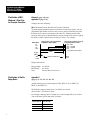
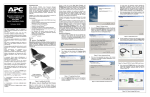
Documentation
Update
DU
Injection Control Module
User's Manual
(Cat. No. 1771-QD/B)
Using This Update
Use this Documentation Update with:
Injection Control Module User’s Manual
(publication 1771-6.5.49) dated June 1990
Injection Control Module User’s Manual Documentation Update
(publication 1771-6.5.49–DU2)
This document:
corrects errors in the previous update 1771-6.5.49-DU2 . . . . . . . . (page 1)
clarifies the definition and application of:
IB31, Minimum Percent Shot Size for Pressure Transition . . . . . (page 2)
Profile Ramp Rates . . . . . . . . . . . . . . . . . . . . . . . . . . . . . . . . . (page 2)
describes enhancements for Revision C of the 1771-QD/B module (page 4)
Keep this document with your manual.
Correct Errors in DU2
for Appendices A and C
Disregard the corrections to pages A-1 and C-6 in documentation update
1771-6.5.49-DU2. The original manual was correct for these pages.
(Page A-1) The following original ranges and units are correct:
[7]
[8]
[9]
0-9999 %-travel per second
0-9999 %-open per second
0-9999 %-close per second
One or more of these changes also appear on pages A-3, A-5, A-6, and A-9.
(Page C-6) The following original ranges and units are correct:
Integer Range 0 to 09999 (9999% = full stroke in 10ms)
BCD Range
0 to 9999
Units
Percent travel per second
This change also appears on pages C-6, C-22, C-24, C-32, C-39, C-40, C-52.
Injection Control Module
(Cat. No. 1771QD/B)
Documentation Update
Clarification of IB31,
Minimum % Shot Size
for Pressure Transition
Chapter 2 (page 2-8) and
Appendix C (page C-21)
Change text to the following:
IB31 Minimum Percent Shot Size for Pressure Transition
To guard against premature pressure transitions from pressure spikes, you can
program the QD module to allow a ram or cavity pressure transition only after
the ram (screw) injects a percentage of the shot size. Starting near the back
point, the ram (screw) is inhibited from a pressure transition as it moves right to
left until it reaches a percent shot size that you select. For example:
When IB31 is
0%
33%
66%
99.9%
The zone where a pressure transition
is inhibited is shown shaded
Shot Size
(PB28)
Cushion
(PB27)
Direction of Ram Travel
Ram
bottom
and a pressure transition can occur
at any ram position less than *:
PB27 + PB28
PB27 + 0.67(PB28)
PB27 + 0.33(PB28)
PB27
* measured from ram bottom
Back
point
Ranges and units are:
Integer Range 0 to 099.99
BCD Range
0 to 99.99
Units
Percent shot size traversed
Clarification of Profile
Ramp Rates
Appendix C
(pages C-6, -22, -24, -32, -40, -52)
Add the following to word descriptions CB10, IB32,33,41,42, PkB17,18,
HB21,22, and PB35,36;
We define the range of ramp rate as 0 to 9999% per second,
where 9999% = full stroke in 10ms.
For example, ramping 100% of output in 1/4 second equals 400% per second.
You would enter typical ramp rates as follows:
For this ramp rate Enter this value
2
100% in 10ms
9999
100% in 100ms
1000
100% in 250ms
400
Injection Control Module
(Cat. No. 1771QD/B)
Documentation Update
Use this procedure to compute ramp rates:
1.
Convert pressure setpoints to percent of maximum pressure.
(Velocity setpoints already are in units of percent.)
2.
Subtract the setpoints (in percent) to obtain the step change (in percent)
over which you want to ramp.
3.
Determine how fast (in what part of a second) you want the ramp to occur.
4.
Divide the time into the step change from step 2 to compute the ramp rate.
Example:
Compute the acceleration ramp rate required to change from 600 to 1800 PSI in
1/5 second for a system with 2400 PSI maximum pressure.
1.
Convert pressure setpoints to percent of maximum pressure.
600 PSI ÷ 2400 PSI = 25%
2.
1800 PSI ÷ 2400 PSI = 75%
Subtract setpoints to obtain ramp range in percent.
75% – 25% = 50%
3.
Ramp time is 1/5 second, defined in the example problem.
4.
Divide ramp time into the step change to compute the ramp rate.
50% step change ÷ 1/5 second ramp time = 50% x 5 = 250% per second
Answer = 250% per second
Enhancements for
Firmware Revision C
Chapter 10
(page 10-1)
Add to the table at the bottom of page 10-1:
If this
LED
is this
color
Then the QD module
sees this condition
We recommend this
corrective action
ACTIVE
mode.
FAULT
AUTO
green
Lost communication with the processor.
1. Verify the processor is in run
off
flashing
The QD module received a valid
config block, but has not received
a block transfer from the PLC
processor in the timeout period.
2. Check for a processor fault.
3. Troubleshoot your ladder logic.
3
Injection Control Module
(Cat. No. 1771QD/B)
Documentation Update
Enhancements for
Firmware Revision C
(continued)
Appendix A
(page A-3)
Replace
CB36-40
RFU
with the following:
CB36-63
CB64
RFU
Reserved for module – Do not use.
(page A-13)
Replace
IS42-50
RFU
with the following:
IS42
IS43-50
Maximum Cavity Pressure in Injection Phase
RFU
(page A-14)
Replace
PkS15-20
RFU
with the following:
PkS15
PkS16-20
Replace
HS17-20
Maximum Cavity Pressure in Pack Phase
RFU
RFU
with the following:
HS17
HS18-20
4
Maximum Cavity Pressure in Hold Phase
RFU
Injection Control Module
(Cat. No. 1771QD/B)
Documentation Update
Enhancements for
Firmware Revision C
(continued)
Appendix C
(page C-12)
Replace
CB36 thru
CB40
Reserved
Not monitored by the QD module
with the following:
CB36 thru
CB63
CB64
Reserved
Reserved
(page C-88)
Replace
IS42 thru
IS50 Reserved
Not monitored by the QD module
Reserved for module – Do not use
Zero when returned by the QD module
with the following
IS42 Max Cavity Pressure
During Injection
Returns the highest cavity pressure
recorded during the injection phase.
Integer Range 0 to 20000 PSI
0 to 2000.0 Bar
BCD Range
0 to 9999 PSI*
0 to 999.9 Bar*
CB05-B16(14)=0
CB05-B16(14)=1
CB05-B16(14)=0
CB05-B16(14)=1
* Double this value when CB05-B17(15)=1
IS43 thru
IS50 Reserved
Zero when returned by the QD module
(page C-91)
Replace
PkS15 thru
PkS20 Reserved
Zero when returned by the QD module
with the following
PkS15 Max Cavity Pressure
During Pack
Returns the highest cavity pressure
recorded during the pack phase.
Integer Range 0 to 20000 PSI
0 to 2000.0 Bar
BCD Range
0 to 9999 PSI*
0 to 999.9 Bar*
CB05-B16(14)=0
CB05-B16(14)=1
CB05-B16(14)=0
CB05-B16(14)=1
* Double this value when CB05-B17(15)=1
PkS16 thru
PkS20 Reserved
Zero when returned by the QD module
5
Injection Control Module
(Cat. No. 1771QD/B)
Documentation Update
Enhancements for
Firmware Revision C
(continued)
(page C-94)
Replace
HS17 thru
HS20 Reserved
Zero when returned by the QD module
with the following
HS17 Max Cavity Pressure
During Hold
Returns the highest cavity pressure
recorded during the hold phase.
Integer Range 0 to 20000 PSI
0 to 2000.0 Bar
BCD Range
0 to 9999 PSI*
0 to 999.9 Bar*
CB05-B16(14)=0
CB05-B16(14)=1
CB05-B16(14)=0
CB05-B16(14)=1
* Double this value when CB05-B17(15)=1
HS18 thru
HS20 Reserved
With offices in major cities worldwide
WORLD
HEADQUARTERS
Allen-Bradley
1201 South Second Street
Milwaukee, WI 53204 USA
Tel: (414) 382-2000
Telex: 43 11 016
FAX: (414) 382-4444
EUROPE/MIDDLE
EAST/AFRICA
HEADQUARTERS
Allen-Bradley Europa B.V.
Amsterdamseweg 15
1422 AC Uithoorn
The Netherlands
Tel: (31) 2975/60611
Telex: (844) 18042
FAX: (31) 2975/60222
Publication
1771-6.5.49-DU3 – January 1992
6
Zero when returned by the QD module
As a subsidiary of Rockwell International, one of the world’s largest technology
companies — Allen-Bradley meets today’s challenges of industrial automation with over
85 years of practical plant-floor experience. More than 13,000 employees throughout the
world design, manufacture and apply a wide range of control and automation products
and supporting services to help our customers continuously improve quality, productivity
and time to market. These products and services not only control individual machines but
integrate the manufacturing process, while providing access to vital plant floor data that
can be used to support decision-making throughout the enterprise.
ASIA/PACIFIC
HEADQUARTERS
Allen-Bradley (Hong Kong)
Limited
Room 1006, Block B, Sea
View Estate
28 Watson Road
Hong Kong
Tel: (852) 887-4788
Telex: (780) 64347
FAX: (852) 510-9436
CANADA
HEADQUARTERS
Allen-Bradley Canada
Limited
135 Dundas Street
Cambridge, Ontario N1R
5X1
Canada
Tel: (519) 623-1810
FAX: (519) 623-8930
LATIN AMERICA
HEADQUARTERS
Allen-Bradley
1201 South Second Street
Milwaukee, WI 53204 USA
Tel: (414) 382-2000
Telex: 43 11 016
FAX: (414) 382-2400
PN 955111-33
Copyright 1992 Allen-Bradley Company, Inc. Printed in USA