1
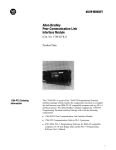
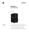
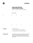
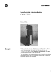
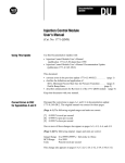
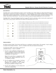
Documentation Update
Allen-Bradley
BASIC Module User’s Manual
(Cat. No. 1771-DB)
Use This Update With:
Publication 1771-6.5.34, BASIC Module (Cat. No. 1771-DB) User’s
Manual, dated July, 1987.
Connecting a T1, T2, T3 or T4
Industrial Terminal to the
Program Port
Use the following table to determine which keyboards you can use with
your 1770-TA Monitor.
1770-TA Monitor
Terminal
Series A
Series B
1770-T3 Terminal
1770-FD Keyboard1
Series A, Revision H
not applicable
Use Port C cable configuration.
Refer to (figure 4.3) in your user’s
manual.
1770-T3 terminal
1770-FD Keyboard1
Series C, Revision H
not applicable
Use Port C cable configuration.
Refer to (figure 4.3) in your user’s
manual.
1770-T3 Terminal
1770-FD Keyboard1
Series C, Revision H
not applicable
Use Port C cable configuration.
Refer to (figure 4.3) in your user’s
manual.
1770-T1 Terminal
1770-FC Keyboard
Use Port B cable configuration.
Refer to (figure 4.3B) below
2
1770-T1 Terminal
1770-FA Keyboard
Use Port B cable configuration.
Refer to (figure 4.3B) below
2
1770-T4 Terminal
1770-FE Keyboard
Series A, Revision F
not applicable
Use Port C cable configuration.
Refer to (figure 4.3) in your user’s
manual.
1
If your firmware revision is earlier than the following you should update your keyboard to the
latest revision
1770-FD Series A, Revision H
1770-FD Series B, Revision H
1770-FD Series C, Revision A
1770-FE Series A, Revision F
2
Important: Do not use a 1770-FC or 1770-FA keyboard with a 1770-TA, Series B monitor for
this application. You cannot select Channel C as the main active port.
Documentation Update
BASIC Module User’s Manual
Important: Use the firmware revision level shown on the screen when
the T3/T4 first powers up. Do not use the revision levels listed on the
bottom of the keyboard or back of the T3/T4.4.14.24.34.3A
Figure 4.3B
Cable pinouts for connecting a 1771-db BASIC Module (Program Port) to
a 1770-TA, Series A Monitor (1770-FC or 1770-FA keyboard).
Replace Figure 4.6, “Cable Connection to 1770-HC Printer” with the
following figure:
4.4. Peripheral Port4.44.5
Figure 4.6
Cable pinouts for connecting a 1771-DB BASIC Module to a 1770-HC
Printer
2
Documentation Update
BASIC Module User’s Manual
Important: This cable does not support hardware handshaking.
4.4.3 Connecting a 1770-SA/SB Recorder to the Peripheral Port
Change the figure references in section 4.4.3 from Figure 4.6 to 4.7.
4.4.4 Connecting a 1770-HC Printer to the Peripheral Port
Change the figure reference in section 4.4.4 from Figure 4.7 to 4.6.
4.4.5 Connecting RS-422 Devices
Insert the following paragraph between paragraphs 2 and 3 on page 4-12.
The following cables have 100 Ohm characteristic impedance. Use them
for RS-422 applications. This is not a complete list of available 100 Ohm
cables.
Belden – 9729, 9804, 9829, 8162
Consolidated – 5755, 5980, 5343
Carol – C0829, C0804, C0841, C0500
5.4.31 Statement: STRING
Replace the statement LET $(1) “HELLO” with:
LET $(1) = “HELLO”
5.11 Memory Support Calls
Add the following Important note to section 5.11:
Important: If you use the ONTIME statement in your programs, refer to
Section 5.4.20 for information about using ONTIME with PROGRAM
EXECUTION TRANSFER CALLS.
5.4.20 Statement: ONTIME [expr],[In num]
Add the following section at the end of section 5.4.20.
Using ONTIME with PROGRAM EXECUTION TRANSFER CALLS
The ONTIME feature uses the currently executing program as the basis to
search for the subroutine line # associated with the ONTIME statement. If
the ONTIME statement is executed and control switches to a different
ROM or RAM Program File (e.g. via calls 70-72) then the ONTIME
execution results in one of the 2 undesirable situations that follow:
3
Documentation Update
BASIC Module User’s Manual
1.
The program picks up execution at the same line # in the currently
executing program. This can cause unexpected program operation
and machine operation.
2.
The program terminates operation with an “invalid line number” error
message, if the line # doesn’t exist.
You can avoid this situation by:
1.
disabling the ONTIME feature (with CLOCK 0) before changing to
another program, then enabling it (with CLOCK 1) after returning or;
2.
duplicating the ONTIME routine in all executed programs at the
same line number. This assures that the routine is available for
execution when any program executes.
6.3.1 PLC-Processor Program
Replace Figure 6.2, “Sample BASIC Module Program” with the following
figure.
>5
>10
>20
>30
>40
>50
>60
>70
>80
>90
>95
>100
>110
>120
>125
>130
>140
>150
>160
>170
>180
>190
>200
4
DIM A(5)
REM SET BTW LENGTH TO 5 WORDS
PUSH 5:CALL 4
REM SET BTR LENGTH TO 5 WORDS
PUSH 5:CALL 5
REM READ THE BTW BUFFER
CALL 6
REM CONVERT DATA FROM 3-DIGIT SIGNED BCD TO DB FORMAT
FOR I=1 TO 5
PUSH I: CALL 10: POP A(I)
PRINT A(I),
NEXT I
REM DO A CALCULATION
T=A(1)+A(2)+A(3) +A(4)+A(5):V=T/5
PRINT “AVE=”,V
REM CONVERT DATA FROM DB FORMAT TO 3-DIGIT SIGNED BCD
PUSH T:PUSH 1:CALL 20
PUSH V:PUSH 2:CALL 20
REM WRITE TO THE BTR BUFFER
CALL 7
REM CONTINUE TO BLOCK TRANSFER
GOTO 60
END
Documentation Update
BASIC Module User’s Manual
In Figure 6.3, “Sample PLC-2 Family Ladder Diagram”, change the
following parts of the ladder diagram:
In Rung 2:
BLOCK LENGTH: 05
FILE: 0205 - 0209
In rung 3:
FILE LENGTH: 005
FILE A: 0205-0209
FILE R: 0210-0214
RATE PER SCAN: 005
6.4 PLC-3 Family Processor
In Figure 6.5, “Sample PLC-3 Family Ladder Diagram”, change Rung
Number RM2 from “LENGTH = 10” to “LENGTH = 5”. Change Rung
Number RM3 from “LENGTH =2” to “LENGTH =5”.
5
Documentation Update
BASIC Module User’s Manual
6.5 PLC-5 Family Processor
Replace Figure 6.7, “Sample PLC-5 Family Ladder Logic”, with the
following figure:
With offices in major cities worldwide
WORLD
HEADQUARTERS
Allen-Bradley
1201 South Second Street
Milwaukee, WI 53204 USA
Tel: (1) 414 382-2000
Telex: 43 11 016
FAX: (1) 414 382-4444
EUROPE/MIDDLE
EAST/AFRICA
HEADQUARTERS
Allen-Bradley Europe B.V.
Amsterdamseweg 15
1422 AC Uithoorn
The Netherlands
Tel: (31) 2975/43500
Telex: (844) 18042
FAX: (31) 2975/60222
Publication 1771–6.5.34–DU1 — March 1990
As a subsidiary of Rockwell International, one of the world’s largest technology
companies — Allen-Bradley meets today’s challenges of industrial automation with over
85 years of practical plant-floor experience. More than 11,000 employees throughout the
world design, manufacture and apply a wide range of control and automation products
and supporting services to help our customers continuously improve quality, productivity
and time to market. These products and services not only control individual machines but
integrate the manufacturing process, while providing access to vital plant floor data that
can be used to support decision-making throughout the enterprise.
ASIA/PACIFIC
HEADQUARTERS
Allen-Bradley (Hong Kong)
Limited
Room 1006, Block B, Sea
View Estate
28 Watson Road
Hong Kong
Tel: (852) 887-4788
Telex: (780) 64347
FAX: (852) 510-9436
CANADA
HEADQUARTERS
Allen-Bradley Canada
Limited
135 Dundas Street
Cambridge, Ontario N1R
5X1
Canada
Tel: (1) 519 623-1810
FAX: (1) 519 623-8930
LATIN AMERICA
HEADQUARTERS
Allen-Bradley
1201 South Second Street
Milwaukee, WI 53204 USA
Tel: (1) 414 382-2000
Telex: 43 11 016
FAX: (1) 414 382-2400
PN 955106–01
Printed in USA
6