1
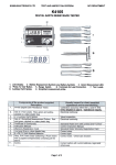
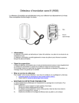
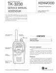
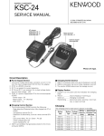
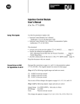
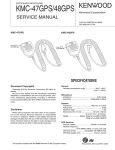
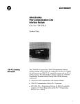
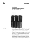
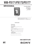
Document Copyrights
Copyright 2006 by Kenwood Corporation. All rights reserved.
No part of this manual may be reproduced, translated, distributed, or transmitted in any
form or by any means, electronic, mechanical, photocopying, recording, or otherwise, for
any purpose without the prior written permission of Kenwood.
Disclaimer
While every precaution has been taken in the preparation of this manual, Kenwood
assumes no responsibility for errors or omissions. Neither is any liability assumed for
damages resulting from the use of the information contained herein. Kenwood reserves
the right to make changes to any products herein at any time for improvement purposes.
MICROPHONE / KEYPAD MICROPHONE
KMC-35/36
SERVICE MANUAL
© 2004-7 PRINTED IN JAPAN
B51-8697-00 (N) 1309
KMC-35
Lever knob (PTT)
(K29-9333-08)
Curl cable
(E30-7531-08)
KMC-36
Lever knob (PTT)
(K29-9333-08)
Curl cable
(E30-7531-08)
Key top
(K29-9335-08)
PARTS LIST
✽ : New parts
KMC-35 (Y58-3740-20), KMC-36 (Y58-3750-20)
Ref. No.
New
parts
Parts No.
Description
1
2
✽
E30-7531-08
E58-0475-05
CURL CABLE
MODULAR JACK
3
4
✽
✽
G01-4546-08
G53-1646-08
COIL SPRING (PTT)
PACKING
5
6
✽
✽
J19-5479-08
J19-5482-05
MIC HOLDER
MIC HANGER (ACCESSORY)
7
8
9
✽
✽
✽
K29-9333-08
K29-9334-08
K29-9335-08
LEVER KNOB (PTT)
KNOB (PTT)
KEY TOP
N52-3012-60
PAN HEAD TAPPING SCREW
S70-0499-08
TACT SWITCH
T91-0538-05
MIC ELEMENT
A
10
11
✽
Destination
KMC-36
KMC-35/36
DISASSEMBLY FOR REPAIR
■ Main PCB removal
1. Remove the four screws, the rear case and all-round packing.
2. Lift the switch PCB and remove it from the front case.
(q)
3. Hold the modular connector with your fingers and move it
in the direction indicated by the arrow to install the Main
PCB onto the front case.
Switch PCB
q
3. Lift the upper part of the Main PCB using a pair of tweezers ( w ) and remove the Main PCB.
■ PTT knob installation procedure
w
Main PCB
1. Place the PTT knob in the front case diagonally as shown
in the figure.
2. Hold down the upper part of the PTT knob ( q ) and push
the PTT knob shaft down ( w ) to install the PTT knob onto
the front case.
w
q
■ Main PCB installation procedure
1. Install the microphone holder, spacer and keytop (KMC-36
only) on the front case.
2. Tilt the Main PCB and fit the modular connector into the
front case first.
■ Hot microphone modification procedure
1. Lift the jumper with a pair of tweezers or similar tool. ( q )
Note : The jumper is bonded to the board, but not strongly
fixed, so it can be detached by applying light force.
2. Cut the base of the jumper into two parts with a pair of
nippers or similar tool. ( w )
w
q
2
KMC-35/36
CIRCUIT DESCRIPTION
■ Circuit description
Hot Microphone Function
Hot microphone operation can be performed by cutting
the jumper (JP1).
If the jumper is not cut (Normal microphone state), bias
voltage is always applied to the microphone element (Q3 is
always ON) and if the microphone mute of the transceiver to
which the KMC-35/36 is connected is released, modulation
signals can be sent even when the microphone PTT switch is
not pressed.
If the jumper is cut (Hot microphone state), bias voltage is
applied to the microphone element only when the PTT switch
is pressed (Q3 turns ON only when the PTT SW is pressed),
and modulation signals cannot be sent when the microphone
PTT switch is not pressed.
In the Hot microphone state, only microphones whose
PTT switch is pressed can send modulation signals in the
environment in which several microphones are connected to
the transceiver in parallel.
In the Normal microphone state, if the PTT switch on one
of the microphones is pressed, modulation signals are sent
from all microphones.
5V
Q1
DTC114EUA
R2 10k
6 MIC
L6
7 HK(HOOK)
L7
C7
1u 16
C9
10u 16
R8
R9
1.5k
*L8
8 DM
E58-0475-05
1k
R5 10k
L5
R7 3.9k
5 ME(MIC GND)
R6 0
MIC
C11
L4
R3 10k
L3
4 PTT
0.068u
L2
3 GND
S1
PTT SW
2 SB
C10
*L1
S70-0499-08
1 BLC
C6 1000p
J1
R4 3.9k
Q3
DTA144EUA
470p
Q2
DTC144EUA
JP1
C20 1000p
R1 10k
R10 0
1000p
100p
1000p
1000p
1000p
*C16
C12
C17
C13
C18
C14
*C19
*C5
*C15
T91-0538-05
3
KMC-35/36
EXPLODED VIEW
KMC-35
KMC-36
8 Knob (PTT)
(K29-9334-08)
8 Knob (PTT)
(K29-9334-08)
3 Coil spring (PTT)
(G01-4546-08)
3 Coil spring (PTT)
(G01-4546-08)
5 MIC holder
(J19-5479-08)
5 MIC holder
(J19-5479-08)
700 Spacer
700 Spacer
7 Lever knob (PTT)
(K29-9333-08)
7 Lever knob (PTT)
(K29-9333-08)
9 Key top
(K29-9335-08)
11 MIC element
(T91-0538-05)
10 Tact switch
(S70-0499-08)
2 Modular jack
(E58-0475-05)
4 Packing
(G53-1646-08)
1 Curl cable
(E30-7531-08)
6 MIC hanger
(J19-5482-05)
701 Model name plate
A
A
A
A M3 x 12 : N52-3012-60
A
Parts with the exploded numbers larger than 700 are not supplied.
4
1 BLC
3 GND
8
7
6
5
4
3
L5
YELLOW
GRAY
WHITE
SHIELD
BLUE
BLACK
RED
GREEN
*L8
L7
L6
R6 0
E
C2 0.1u
HK
MIC
MIC-E
PTT
1
R10 0
8
7
6
5
4
3
2
Q1
DTC114EUA
Q2
DTC144EUA
R1 10k
C4 1000p
C3 0.1u
8P MODULAR PLUG
C20 1000p
1k
R8
Q3
DTA144EUA
C9
10u 16
C7
1u 16
T91-0538-05
MIC
*C25 100p
*D23
*D24
L92-0444-05
L92-0444-05
KMC-36
L8
*D26
*D27
C15
NO
NO
1000p 1000p
C5
*Q22
2SA1162(Y)
*R37 1k
NO
L1
*Q21
2SC2712
(Y)
100
100
100
100
NO
L9
KMC-35
*Q23
2SC2712(Y)
*R22
*R23
*R24
*R25
*C26
NO
1000p
NO
100p
C19
TC4017BF
YES
NO
A
1000p
8
7
6
5
4
3
2
1
8
Q8
VSS
7
Q4
Q3
6
Q9
Q7
5
CAR Q6
4
INH
Q2
3
CLK
Q0
2
RST
Q1
1
VDD Q5
*IC22
TC4017BF
Q8 VSS
Q4
Q3
Q9
Q7
CAR Q6
INH
Q2
CLK
Q0
RST Q1
VDD Q5
C16
9
10
11
12
13
14
15
16
9
10
11
12
13
14
15
16
*IC21
*R41 0
1.5k
1.5k
1.5k
1.5k
2.7k
*R38
*R36
*R34
*R35
*R39
*R29 1.5k
*R30 1.5k
*R31 1.5k
*Q24
DTC114EUA
9
#
0
*
6
8
5
4
3
7
2
1
SCHEMATIC DIAGRAM
2
1
L3
L4
COM
2
*R21 0
D
8P MODULAR PLUG
*C15
1
S70-0499-08
OUT
R2 10k
C10
IN
C
CORD ASSEMBLY
HANGER PLATE
HANGER KNOB
E58-0475-05
8 DM
7 HK(HOOK)
6 MIC
5 ME(MIC GND)
4 PTT
L2
*L1
C1 1000p
1000p
100p
1000p
1000p
1000p
2 SB
3
C6 1000p
R9
1.5k
R3 10k
JP1
J1
*C5
S1
PTT SW
0.068u
R4 3.9k
C11
R5 10k
R7 3.9k
470p
220k
10k
*R26
*R32
0
*R43
A
B
*C16
C12
C17
C13
C18
C14
*C19
0
IC1
NJM78L05UA
*R40
*D25
1SS184
10k
47k
*R42
*R28 33k
*C22 1000p
*R27 1k
*R33 22k
*C21 1000p
*R44
A
E
KMC-35/36
1
2
3
4
5
6
7
5
KMC-35/36
SPECIFICATIONS
Voltage Required ....................................... 13.6V± 15%
Operating Temperature Range.................. –30°C~+60°C
Microphone Sensitivity.............................. –46dB± 6dB at 1kHz (0dB=1V/Pa)
Impedance ................................................ 1kΩ± 30% at 1kHz
Current Drain ............................................. Less than 20mA (KMC-35)
Less than 100mA (KMC-36)
KENWOOD CORPORATION
2967-3, Ishikawa-machi, Hachioji-shi, Tokyo, 192-8525 Japan
KENWOOD U.S.A. CORPORATION
P.O. BOX 22745, 2201 East Dominguez Street, Long Beach, CA 90801-5745, U.S.A.
KENWOOD ELECTRONICS CANADA INC.
6070 Kestrel Road, Mississauga, Ontario, Canada L5T 1S8
KENWOOD ELECTRONICS DEUTSCHLAND GMBH
Rembrücker Str. 15, 63150 Heusenstamm, Germany
KENWOOD ELECTRONICS BELGIUM N.V.
Leuvensesteenweg 248 J, 1800 Vilvoorde, Belgium
KENWOOD ELECTRONICS FRANCE S.A.
13, Boulevard Ney, 75018 Paris, France
KENWOOD ELECTRONICS U.K. LIMITED
KENWOOD House, Dwight Road, Watford, Herts., WD18 9EB United Kingdom
KENWOOD ELECTRONICS EUROPE B.V.
Amsterdamseweg 37, 1422 AC Uithoorn, The Netherlands
KENWOOD ELECTRONICS ITALIA S.p.A.
Via G. Sirtori, 7/9 20129 Milano, Italy
KENWOOD IBERICA S.A.
Bolivia, 239-08020 Barcelona, Spain
KENWOOD ELECTRONICS AUSTRALIA PTY. LTD.
(A.C.N. 001 499 074)
16 Giffnock Avenue, Centrecourt Estate, North Ryde, N.S.W. 2113 Australia
KENWOOD ELECTRONICS (HONG KONG) LTD.
Unit 3712-3724, Level 37, Tower one Metroplaza, 223 Hing Fong Road, Kwai Fong, N.T., Hong Kong
KENWOOD ELECTRONICS SINGAPORE PTE LTD.
1 Genting Lane #07-00 Kenwood Building, Singapore 349544