1
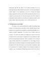
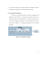
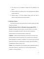
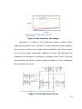
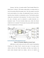
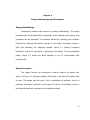
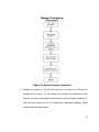
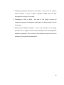
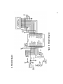
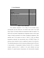
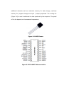
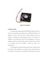
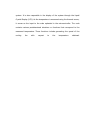
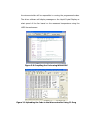
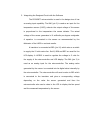
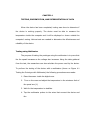
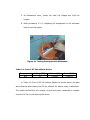
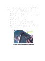
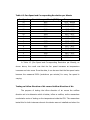
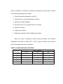
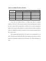
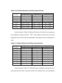
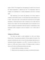
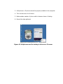
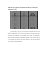
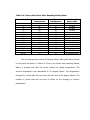
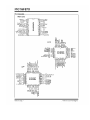
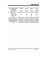
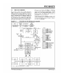
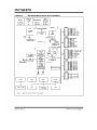
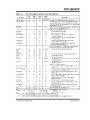
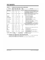
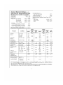
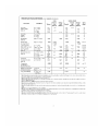
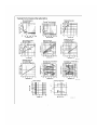
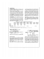
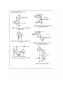
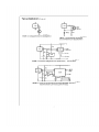
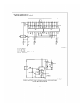
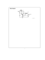
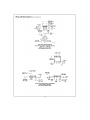
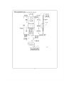
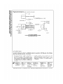
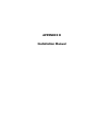
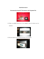
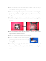
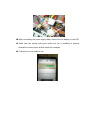
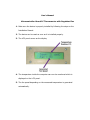
Microcontroller-Based PC Thermometer
with Regulated Fan
By
James Christian B. Aspillaga
Reinald Carlo A. Roque
Ishmael Angelo F. Sanchez III
A Design Report Submitted to the School of Electrical Engineering,
Electronics and Communications Engineering, and Computer
Engineering in Partial Fulfillment of the Requirements for the Degree
Bachelor of Science in Computer Engineering
Mapua Institute of Technology
January 2009
ACKNOWLEDGEMENT
We thank the Lord for all the blessings you have given us, for the lives
you have given to us. Without your power and your guidance, we would not be
able to finish this work.
We would also like to thank our parents, for without them, we would not
be where we are today. Our parents were the ones who guided us and provided
us our wants and needs. They are our inspirations in finishing this work. Now,
we want to return a part of their hard work by means of this project.
We would also like to give thanks for our friends and family members for
giving us support in every endeavor we undertake.
TABLE OF CONTENTS
TITLE PAGE
i
APPROVAL SHEET
ii
ACKNOWLEDGEMENT
iii
TABLE OF CONTENTS
iv
LIST OF TABLES
v
LIST OF FIGURES
vi
ABSTRACT
vii
Chapter 1: DESIGN BACKGROUND AND INTRODUCTION
1
The Design Setting
Statement of the Problem
The Objective of the Design
The Significance of the Design
The Conceptual Framework
The Scope and Delimitation
Definition of Terms
1
2
2
3
4
5
6
Chapter 2: REVIEW OF RELATED LITERATURE
10
Chapter 3: DESIGN METHODOLGY AND PROCEDURES
15
Design Methodology
Design Procedure
Hardware Design
Block Diagram
Schematic Diagram
List of Materials
Software Design
System Flowchart
Prototype Development
Chapter 4: TESTING, PRESENTATION, AND INTERPRETATION OF DATA
Testing using Multimeter
Testing Fan Speed with Digital Tachometer
15
15
18
18
19
20
22
24
25
29
29
31
Testing on Inflow Direction of Air versus Outflow Direction of
Air
Testing on a VOIP server
Chapter 5: CONCLUSION AND RECOMMENDATION
Conclusion
Recommendation
33
37
41
41
41
References
43
Appendices
44
Appendix
Appendix
Appendix
Appendix
Appendix
A: Source Code
B: PIC16F87x Data Sheet
C: LM35 Data Sheet
D: Installation Manual
E: User’s Manual
44
57
65
78
82
LIST OF TABLES
Table
Table
Table
Table
Table
Table
Table
Table
Table
3.1 List of Materials
4.1: Test of DC Fan without Device
4.2: Test of DC Fan with Device
4.3 Fan Speed and Corresponding Revolution per Minute
4.4 Inflow Direction of Airflow
4.5 Outflow Direction of Airflow
4.6 Outflow Direction of Airflow since Start-Up
4.7 Inflow Direction of Airflow since Start-Up
4.8 Test on the first few minutes after boot-up at initial CPU
temperature of 29ºC
Table 4.9 Test on the Server after Reaching Steady State
20
30
31
33
34
35
36
36
39
40
LIST OF FIGURES
Figure
Figure
Figure
Figure
Figure
Figure
Figure
Figure
Figure
Figure
Figure
Figure
Figure
Figure
Figure
Figure
Figure
1.1
2.1
2.2
2.3
2.4
3.1
3.2
3.3
3.4
3.5
3.6
3.7
3.8
3.9
4.1
4.2
4.3
Conceptual Framework
Fan Speed vs. Fan Voltage
Fan Current vs. Fan Voltage
Linear Fan-Control Circuit
Thermistor Based Fan-Control Circuit
Design Procedure Flowchart
Block Diagram
Schematic Diagram
LM35 Sensor
PIC16F877 Microcontroller
Cooling Fan
System Flowchart
Compiling the Code using MPLAB IDE
Uploading the Code to the Microcontroller Using IC-Prog
Testing Prototype with Multimeter
Testing Fan Speed using Tachometer
Softphones used for testing in Voice over IP server
4
10
11
11
12
16
18
19
21
21
22
24
27
27
30
32
38
ABSTRACT
This device is a temperature monitoring device with regulated fan for
computers. The purpose of this study is to develop a circuit that adjusts the
motor speed of computer cooling fan/s depending on the measured temperature.
A thermal sensor is used to measure the temperature of the computer. The
device is also integrated with a microcontroller which enables the cooling fan to
attain a variable motor speed depending on the measured temperature. Varying
the motor speed of the fan results to lesser power consumption. The researchers
used the multimeter to test the conservation of power consumption and a digital
tachometer to test the varying motor speed of the fan. Findings of this study
showed that using a thermal sensor, microcontroller and other components, a
computer cooling fan can vary its motor speed and reduce power consumption.
Keywords: Thermal sensor, Microcontroller, Computer
8
Chapter 1
DESIGN BACKGROUND AND INTRODUCTION
1. The Design Setting
Over the past ten years, computers have increased their heat output
considerably. Even a cursory glance at a modern server reveals the huge
amount of effort that the designers had to take to keep the computer cool.
Not only do the processors have massive heat sinks, but the server also gets
fully loaded with fans. In extreme cases, liquid cooling is necessary. The bad
news is that things are getting worse. Processor speeds are going up; heat
generation is climbing too.
Computers are now very important to our daily lives. They are used in
businesses, for educational purposes, and almost everything can be done
using a computer. That is why proper care for these computers is very
essential. Some people use their computers for a long period of time. One
problem that may occur is overheating of the computer resulting to loss of
valuable data and even worse, destruction or cutting short the life of the
computer system’s components. For servers, temperature monitoring is an
issue; if the server becomes too hot, it can cause to down time in servers.
The cost of a catastrophic server failure can be considerable. Much costs
would be met if the server goes down. There is the cost of replacement, loss
9
of e-commerce business, loss of customers details, waste of staff time and all
the other associated costs.
2. Statement of the Problem
Computer equipment ages faster when it gets hot. In general,
computer operates more reliably and has a longer life in cooler conditions.
The effects of prolonged running at high temperatures can be unpredictable
and are not always characterized by catastrophic failures.
For individual machines, in domestic or small office conditions the
internal fans and cooling mechanism are usually sufficient to keep the
temperature within safe. But if the machine is used in a business wherein the
uptime of the machine is critical and is used for a long time. Temperature
monitor is important.
Temperature monitoring is essential for CPU especially if it is used for
server. Failure to monitor temperature could result to unnoticed heat buildups in CPU that can reduce the life of components, decrease reliability, cause
untold problems and expense.
3. The Objective of the Design
The objective of this project design is to measure the present
temperature inside the computer and will be displayed on its casing for easier
temperature monitoring and to create a prototype of a computer
10
thermometer that can be placed on the central processing unit as an
additional hardware. Using the PIC microcontroller, the team would design an
external display of the temperature on the CPU. Through this external
display, temperature monitoring will be easier especially on servers that are
sharing to one monitor since it will only need one look in the CPU to know the
temperature. Another objective of our design is to determine whether which
airflow is better, either inflow direction of air or outflow direction of air.
4. The Significance of the Design
The design of the device would be very helpful to computer users
because it can help prevent overheating of their computer through proper
monitoring of its temperature and applying a temperature dependent fan to
maintain desirable temperature. The device will be placed inside the
computer. The device will measure the temperature inside the CPU and
introducing a fan into the system to exhaust the hot air around the chassis
and the heat-generating components. When it becomes too hot, the fan’s
speed would be faster and if the temperature is on the average, the fan’s
speed would be normal just to maintain the desirable temperature. Automatic
fan speed control without the need for host intervention is particularly useful
in PC applications for a number of reasons. Once configured, it enables the
system to react to temperature changes and ensures that the fan will run
11
only as fast as required for any given temperature, minimizing the power
consumption and reducing the noise level generated by the fan.
5. The Conceptual Framework
The device is microcontroller-based to monitor the temperature and
regulate the speed of the fan. It contains all the programs needed to have
the accurate reading of the thermometer and to control the fan speed. There
is also an LCD display that indicates the current temperature inside the
casing. Refer to Figure 1.1 for graphical presentation of the conceptual
framework.
Figure 1.1 Conceptual Framework
12
6. The Scope and Delimitation
The study was concerned with the development of a design called
Microcontroller-based PC Thermometer with Regulated Fan that serves as a
cooling and temperature monitoring of a computer. The research study set
the scope and delimitation as follows:
1. The prototype can be place in any computer that has CD/DVD ROM rack
of the CPU as an additional hardware;
2. The LCD will only display the current temperature inside the casing and
corresponding fan speed;
3. The device receives its power from the computer’s PSU (Power Supply
Unit) that produces 5V and 12V;
4. The sensor can be mounted in any part of the CPU that needs
temperature monitoring;
5. The thermally activated fan is included to help maintaining desirable
temperature inside the CPU; and
6. The prototype is designed for server use.
The delimitations of the design of the “Microcontroller-based PC
Thermometer with Regulated Fan” are as follows:
1. The LCD can only display the current temperature inside the casing in
degrees Celsius format;
2. There should be an available connector from the PSU (Power Supply
Unit) as a source of power;
13
3. The casing has to be modified to acquire the full potential of the
device;
4. Different model of the internal parts of the motherboard has different
tolerable heat; and
5. Different design of CPU has different airflow which can lead to
different result if tested with another computer.
7. Definition of Terms
The group encountered some terms that were used throughout the study.
These are as follows:
American Standard Code for Information Interchange (ASCII) – a
standard for assigning numerical values to the set of letters in the Roman
alphabet and typographic characters. (Microcontrollers: Architecture,
Implementation and Programming Boston, McGraw-Hill)
Capacitor - a passive element designed to store energy in its electric field,
the most common electrical components. It is consisted of two conducting
plates separated by an insulator (or dielectric). It is an open circuit to dc used
extensively in electronics, communications, computer, and power systems.
(Fundamentals of Electric Circuits, 2004)
Celsius - using or measured on an international metric temperature scale on
which water freezes at 0° and boils at 100° under normal atmospheric
conditions. (University Physics)
14
Central Processing Unit (CPU) - part of the computer that holds the main
components like mother board and video card. This is usually enclosed in a
casing. (Computer Concepts and Fundamentals)
Current - current, flow of electric charge. The electric charge in a current is
carried by minute particles called electrons that orbit the nuclei of atoms.
(Fundamentals of Electric Circuits, 2004)
Direct Current (DC) - unidirectional flow of electric charge. Direct current is
produced by such sources as batteries, thermocouples, solar cells, and
commutator-type electric machines of the dynamo type. (Fundamentals of
Electric Circuits, 2004)
Frequency - the number of times a specified periodic phenomenon occurs
within a specified interval (University Physics)
Light Emitting Diode (LED) - a semiconductor diode that emits light when
conducting current, and is used in electronic equipment, especially for
displaying readings on digital watches, calculators, etc. (Computer Concepts
and Fundamentals)
Linear Regulation - adjusts the dc voltage across the fan using a linear
regulator. (Electronics Design, Strategy, News)
Microcontroller - single purpose processing units designed to execute small
control programs, sometimes in real time. The program is frequently stored
on the microcontroller in an area of nonvolatile memory. (Handbook of
Microcontrollers)
15
Multimeter - an electronic measuring instrument that combines multiple
functions; a combined voltmeter, ammeter and ohmmeter. (Fundamentals of
Electric Circuits)
Nybble - the computing term for a four-bit aggregation, or half an octet (an
octet being an 8-bit byte). As a nibble contains 4 bits, there are sixteen
possible values, so a nibble corresponds to a single hexadecimal digit.
(Computer Concepts and Fundamentals)
PIC - a family of Harvard architecture microcontrollers made by Microchip
Technology, derived from the PIC1640 originally developed by General
Instrument's Microelectronics Division. The name PIC initially referred to
"Programmable Interface Controller", but shortly thereafter was renamed
"Programmable Intelligent Computer". (Handbook of Microcontrollers)
Programmable Logic Device (PLD) - an electronic component used to
build reconfigurable digital circuits. Unlike a logic gate, which has a fixed
function, a PLD has an undefined function at the time of manufacture.
(Computer Concepts and Fundamentals)
Rectifier Diode - a semiconductor device that converts ac into pulsating dc;
one part of a power supply. (Electronic Devices, 2002)
Resistor - the simplest passive element. It is a device that has the ability to
resist the flow of electric current that is measured in ohms. It is usually made
from metallic alloys and carbon compounds. (Fundamentals of Electric
Circuits, 2004)
16
Thermistor - a resistor whose resistance varies as a function of
temperature. Thermistors are used in electrical devices such as thermometers
and thermostats that measure, monitor, or regulate temperature.
(Fundamentals of Electric Circuits)
Transistor - a semiconductive device used for amplification and switching
applications. (Electronic Devices, 2002)
Tachometer - an instrument that measures the speed of rotation of the
engine, in revolutions per minute (rpm). (University Physics)
Voltage - electric potential expressed in volts (University Physics)
17
Chapter 2
REVIEW OF RELATED LITERATURE AND RELATED STUDIES
In an article entitled “Cooling Down with Fan-Speed Control” on
September 28, 2000, Bruce Denmark conducted a study that gave an important
contribution to our study which is to develop a device that can display the
temperature of computer and maintain a desirable temperature inside the
computer. He said that introducing fan-speed control into electronic designs can
help in reducing heat problems. He also discussed the different methods in which
fan-speed control can be achieved, like Pulse-Width Modulation, Linear
Regulation and DC/DC Regulation. In Mr. Denmark’s article, he mentioned that
“as the dc voltage applied to the fan varies, its speed and current draw also
vary” as portrayed in Figure 2.1. He also mentioned that “the speed and current
of the dc fan are directly proportional to the dc voltage applied” as shown in
Figure 2.2.
Figure 2.1 Fan Speed vs. Fan Voltage
18
Figure 2.2 Fan Current vs. Fan Voltage
Furthermore, an article by Jim Christensen, which is entitled “Circuit
Generates Fan-Speed Control” on March 21, 2002, states that “linear regulation”
can be used to control the fan-speed, which he showed in his circuit in Figure
2.3, as for our design “pulse-width modulation” is used. This study gave the
researchers an alternative in producing a fan-speed control circuit. The group
also considered this study to gather relevant information like the components
that he used for the circuit.
Figure 2.3 Linear Fan-Control Circuit
19
Moreover, John Guy in his article entitled “Circuit Provides Efficient FanSpeed Control” on March 4, 2004 made a study similar to our design which is a
circuit that provides efficient fan-speed control. John Guy created a circuit that
has the same objective of our design. He implemented his logic to control fanspeed by using a thermistor as a temperature monitor. The thermistor produces
voltage that is proportional to the temperature. The circuit, as shown in Figure
2.4, uses a thermistor, gave the researchers’ a possible alternative as a
temperature sensor. The circuit included multiple power outlets that allowed
multiple fans to be connected. This study gave the group possible improvements
that can be implemented on the design.
Figure 2.4 Thermistor Based Fan-Control Circuit
Additionally, an article written by Ken Gay (2007) entitled “Understanding
Closed-Loop Fan Speed Control”, showed two types of fan speed control
variation which are the Closed Loop Variation and Open Loop Variation. His
article mostly discussed closed loop variation, what are its benefits and
20
advantages. This gave the group the knowledge that there were two types of
variation. The group also learned that closed loop variation uses a tachometer in
order to adjust its speed.
In Mr. Darrin Vallis’ article entitled “Closed-Loop Fan Control at System
Level”, (2004) he discussed briefly the disadvantages of an open loop and how
closed loop can be better in comparison. This article gave the group a wider
knowledge on the advantages of a closed loop. The article also discussed that a
tachometer feedback is used in a closed loop variation. Mr Vallis also discussed in
his article what tachometer feedback is and how it works.
In addition, Myke Predro (1997), in his book entitled “Handbook of
Microcontrollers” discussed Motor Control and LCD Control. The article discussed
the different methods that can be used to control motors. The article discussed
that the easiest way to control motors is to switch them on and off. This study
was used by the group since the project involved is controlling the fan speed
depending on the temperature. The article suggested that controlling the motor
speed is normally done by pulsing the control signals in the form of a pulse wave
modulated signal, which is usually called Pulse Width Modulation. The group
used the knowledge gained from the article about pulse width modulation and
other methods on controlling motors in the design of the project. Also, the article
on LCD control focused on the discussion on how to use an LCD. The article also
discussed the basic pin configuration usually used. The article was used by the
group to gather information on LCD, how they work and how the LCD can be
21
connected to the microcontroller. The article is very helpful to the researchers
since the article was very in-depth in its discussion.
Lastly, Myke Predro (2000) in his article entitled “Programming and
Customizing PIC Micro Microcontrollers Second Edition”, discussed pulse-width
modulation (PWM) in detail. It explained that using pulse-width modulation is the
best way to handle analog voltages and that PICmicro MCU does not handle
voltages very well. The study also discussed that analog signals should not be
used for data transfer. His article was useful to our study since pulse-width
modulation is also the method we used in our design.
22
Chapter 3
Design Methodology and Procedures
Design Methodology
Constructive research was used as the design methodology. The design
procedure part will provide further explanation of the method and a step by step
procedure will be discussed. The research started by identifying the problem.
Followed by collecting information relevant to the study, formulating a plan or
draft and gathering the materials needed. Figure 3.1 (Design Procedure
Flowchart) shows the procedure in developing the design. On the succeeding
pages, Figure 3.2 shows the block diagram of the PC thermometer with
regulated fan.
Design Procedure
The design follows the constructive research method as stated from
above. On figure 3.1 (Design Procedure Flowchart) it will clarify the details step
by step. The design has four parts: first is identifying the problem, second is
collecting information relevant to the study, the third is formulating a plan or
draft and the last part is gathering the materials needed.
23
Figure 3.1 Design Procedure Flowchart
1. Identify the problem – the first thing to do in a project is to identify the
problem to be solved. In our design, the problem we identified is that
failure to monitor temperature could result to unnoticed heat build-ups in
CPU that can reduce the life of components, decrease reliability, cause
untold problems and expense.
24
2. Collecting Information Relevant to the Study – this part of the study is
where research is done to gather important details that can help
accomplish the project to be made.
3. Formulating a Plan or Draft – this part of the study is where the
researchers prepare the objectives and tasks to be done needed to finish
the project.
4. Gathering the Materials Needed – this is the last part of the design
procedure of our project in which all the necessary tools and equipments
needed are gathered. This is where all the hardware components and the
software to be used will be determined.
25
a. Hardware Design
1. Block Diagram
Figure 3.2 Block Diagram
In Figure 3.2, as shown above, the power supply of the CPU will be used
as the main source of the hardware. The 12 V will supply the cooling fan and the
5 volts is for the sensor and the microcontroller. When the sensor read
temperature it will send an analog signal to the microcontroller. The
microcontroller will convert the analog signal into its digital value in order for it to
be displayed in the LCD and at the same time it will send a signal to the
transistor
in
order
to
trigger
the
cooling
fan.
26
2. Schematic Diagram
Figure 3.3 Schematic Diagram
27
3. List of Materials
Material
PIC16F877
LM35
LCD 2X16
8 MHz Crystal Oscillator
VNP35
104 Multilayer Capacitor
105 Multilayer Capacitor
¼ watt resistor
1000 microfarad/16v electrolytic capacitor
22picofarad ceramic capacitor
Blower Fan
Heat Sink
2 pins Terminal Block
8 pins Connector
10k array resistor
Table 3.1 List of Materials
Quantity
1
1
1
1
1
1
1
4
1
2
1
1
1
1
1
The essential components of the design are the thermal sensor,
microcontroller and the cooling fan. The thermal sensor which is the LM35
Sensor (Figure 3.4) directly measures the temperature inside the computer. The
LM35 series are precision integrated-circuit temperature sensors, whose output
voltage is linearly proportional to the Celsius (Centigrade) temperature. Other
materials used in the project are shown in Table 3.1. With the different
temperatures measured, the microcontroller which is PIC16F877 (Figure 3.5)
performs various functions the sets or regulates the speed of the cooling fan.
The obtained temperatures and the fan speed are displayed using the LCD panel.
A microcontroller or Programmable Interface Controller (PIC) is a functional
computer system-on-a-chip. In addition to the usual arithmetic and logic
elements of a general purpose microprocessor, the microcontroller integrates
additional elements such as read-write memory for data storage, read-only
memory for program storage and input / output peripherals. The cooling fan
(Figure 3.6) is used to eliminate the heat produced by the computer. The speed
of the fan depends on the measured temperature.
Figure 3.4 LM35 Sensor
Figure 3.5 PIC16F877 Microcontroller
Figure 3.6 Cooling Fan
b. Software Design
The program was developed using the MPLAB IDE Compiler and IC-Prog.
The code was formulated and compiled using the MPLAB IDE Compiler. This
application is used to convert the code to machine language in which the
computer can understand it. After compiling the code, it is now ready to be
uploaded to the microcontroller. Using the IC-Prog application, the code was
uploaded or burned to the microcontroller using also hardware that is connected
to the computer and has the capability of writing the codes to the
microcontroller.
The formulated code includes programs that the major components used
in the system. These components are the thermal sensor, microcontroller and
the cooling fan. The code is the one responsible for the automation of the whole
system. It is also responsible in the display of the system through the Liquid
Crystal Display (LCD). As the temperature is measured using the thermal sensor,
it serves as the input to the code uploaded in the microcontroller. The code
contains various predetermined situations or functions that correspond to the
measured temperature. These functions include generating the speed of the
cooling
fan
with
respect
to
the
temperature
obtained.
1. System Flowchart
Figure 3.7 System Flowchart
The system flowchart as shown in Figure 3.7, explains how the device
works internally. The computer must be turned on. After the computer is turned
on, the temperature will be measured by the LM35 sensor. After measuring the
temperature, it will be displayed on the LCD panel and the corresponding speed
of the fan will be generated accordingly. If the user wants to turn of the system,
the process will end, if not the process will start again at measuring the
temperature.
c. Prototype Development
In creating the design, the researchers gathered the necessary
components and information needed in the design. Components such as
hardware used were identified using the data sheets and through research. The
components used were the solutions to the design problem. The following steps
were used in creating the design:
1. Creation of the Circuit
With all the information and possible solutions gathered, the
researchers collected all the necessary components and designed the
complete circuit of the system. The researchers used Electronics
Workbench MultiSim9 as a tool in designing the circuit. The tool used is an
interactive and user-friendly application that provides circuit simulator and
new integrated circuits.
The device must be first connected to the computer’s power
supply. Once the computer is turned on, the device will also be turned on.
The LCD panel will be activated and will show the measured temperature
and its corresponding fan speed. The temperature will be obtained using
the LM35 thermal sensor and it will be in degrees Celsius. While the
device is running the thermal sensor will continuously measure the
temperature inside the computer and this reading will serve as the input
to the PIC16F877 microcontroller. The LCD panel will display the
measured temperature with the corresponding speed of the fan. The
PIC16F877 microcontroller is programmed to make decisions and perform
functions based on predetermined situations. It will send a function to set
the motor speed of the electric fan to the corresponding temperature.
Lastly, the circuit will continuously be activated unless the user wants to
turn of the system.
2. Creation of the Software
The Liquid Crystal Display (LCD) which serves as the display is
controlled by a driver software. The microcontroller is able to store and
run a program that can be programmed to perform decisions and
functions based on predetermined situation. In programming the PIC
microcontroller, the steps made was: formulate the code, compile the
code and burn the code into a microcontroller. The MPLAB IDE compiler is
used in the system. The source code will be first saved as a text file and
will be run through the compiler (As shown in Figure 3.8). The compiler
will read the saved text file and compiles it to its equivalent machine code
(hex file). The IC-Prog is used for the hex file which is uploaded to the
microcontroller (As shown in Figure 3.9). The central processing unit of
the microcontroller will be responsible in running the programmed codes.
The driver software will display messages on the Liquid Crystal Display on
what speed of the fan based on the measured temperature using the
LM35 thermal sensor.
Figure 3.8 Compiling the Code using MPLAB IDE
Figure 3.9 Uploading the Code to the Microcontroller Using IC-Prog
3. Integrating the Designed Circuit with the Software
The PIC16F877 microcontroller is used in the design since it has
an analog input capability. The RA0 (pin 2) is used as an input for the
temperature sensor (LM35), wherein the output voltage of the sensor
is proportional to the temperature the sensor detects. The actual
voltage of the sensor generates is 10 millivolts per degree centigrade.
A capacitor is connected to the sensor as recommended by the
fabricator of the LM35 to see best results.
A transistor is connected at RE2 (pin 10) which acts as a switch
to supply the 12 volts motor fan. Port B, RD6 and RD7 are used for the
LCD display. A LM7805 is used to regulate the voltage to 5 volts for
the supply of the microcontroller and LCD display. The RA0 (pin 2) is
used as an analog input for the microcontroller. The analog value
generated by the sensor is converted into its digital value internally by
the microcontroller. The microcontroller will send a value to RE2 which
is connected to the transistor and gives a corresponding voltage
depending on the value the sensor generated and then the
microcontroller also send a value to the LCD to display the fan speed
and the measured temperature by the sensor.
CHAPTER 4
TESTING, PRESENTATION, AND INTERPRETATION OF DATA
When the device has been completed, testing was done to determine if
the device is working properly. The device must be able to measure the
temperature inside the computer and it will be displayed or shown outside the
computer’s casing. Various tests are needed to determine the effectiveness and
reliability of the device.
Testing using Multimeter
The purpose of testing the prototype using the multimeter is to prove that
the fan speed increases as the voltage also increases. Using the data gathered
from the test, the researchers can also calculate the power used by the device.
To perform the testing of the device with a multimeter (shown on Figure 4.1
Testing the Prototype with Multimeter) the following procedures were made:
1. Place the sensor inside the digital oven.
2. Turn on the oven and adjust the temperature to the minimum limit of
fan speed one (1).
3. Wait for the temperature to stabilize.
4. Tap the multimeter probes to the wires that connect the device and
fan.
5. As fluctuations occur, record the read out voltage that hold the
longest.
6. Redo procedures 2 to 5, adjusting the temperature to the minimum
limit of each fan speed.
Figure 4.1 Testing Prototype with Multimeter
Table 4.1: Test of DC Fan without Device
Temperature
N/A
Voltage(DC)
12
Current(A)
0.00042
Power(kW)
5.04E-06
In Table 4.1 (Test of DC Fan without Device) as shown above, the data
were obtained after testing the DC fan without the device using a multimeter.
The results showed that the voltage, current and power measured is constant
since the DC fan is used without the device.
Table 4.2: Test of DC Fan with Device
Temperature
55°C - Above
53°C - 54°C
51°C - 52°C
49°C - 50°C
47°C - 48°C
45°C - 46°C
43°C - 44°C
41°C - 42°C
39°C - 40°C
37°C - 38°C
35°C - 36°C
33°C- 34°C
31°C - 32°C
29°C - 30°C
27°C - 28°C
26°C - Below
Fan speed
15
14
13
12
11
10
9
8
7
6
5
4
3
2
1
0
Voltage(DC)
11.2
10.5
9.9
9.3
8.5
7.9
7.1
6.5
5.9
5.1
4.2
3.4
2.6
2.1
1.45
0.81
Power(kW)
0.000004256
0.000003675
0.000003168
0.00000279
0.00000238
0.000001975
0.000001562
0.0000013
0.000001003
0.000000765
0.000000504
0.00000034
0.000000182
0.000000105
4.35E-08
0
The results after testing the DC fan with the device with the multimeter
are shown in Table 4.2 (Test of DC Fan with Device). From the data obtained,
the fan speed was proven that it varies as voltage is increasing or decreasing.
Also from the data table shown above, power being consumed by the device also
varies when the fan speed changes. When the fan is running at higher speeds, it
will consume more power and when the fan is running at lower speeds power
being consumed decreases.
Testing Fan Speed with Digital Tachometer
The purpose of testing the device with a digital tachometer is to prove
that each fan speed varies depending on the temperature; the researchers used
a Digital Tachometer to measure the RPM for each fan speed. To perform the
testing of the device with a digital tachometer (shown on Figure 4.2 Testing Fan
Speed using Tachometer) the following procedures were made:
1. Stick the reflector in the middle of the fan.
2. Place the sensor inside the digital oven.
3. Turn on the oven and adjust the temperature to the minimum limit of
fan speed one (1).
4. Wait for the temperature to stabilize.
5. Position the tachometer in front of the reflector sticker.
6. As fluctuations occur, record the RPM that holds the longest.
7. Repeat procedures 3 to 6, adjusting the temperature to the minimum
limit of each fan speed.
Figure 4.2 Testing Fan Speed using Tachometer
Table 4.3: Fan Speed and Corresponding Revolution per Minute
Fan Speed
15
14
13
12
11
10
9
8
7
6
5
4
3
2
1
0
Revolutions per Minute (RPM)
2847
2760
2698
2640
2556
2443
2364
2263
2175
2023
1850
1670
1450
1225
803
0
Temperature
55°C - Above
53°C - 54°C
51°C - 52°C
49°C - 50°C
47°C - 48°C
45°C - 46°C
43°C - 44°C
41°C - 42°C
39°C - 40°C
37°C - 38°C
35°C - 36°C
33°C- 34°C
31°C - 32°C
29°C - 30°C
27°C - 28°C
26°C - Below
In Table 4.3 (Fan Speed and Corresponding Revolution per Minute), as
shown above, the result was that the fan speed increases as temperature
increases and vice versa. From the data, it can be seen that the fan speed varies
because the measured RPM (revolutions per minute) for every fan speed is
varying.
Testing on Inflow Direction of Air versus Outflow Direction of Air:
The purpose of testing the inflow direction of air versus the outflow
direction air is to determine which is better; inflow or outflow, as the researchers
conducted a series of testing on the temperature inside the CPU. The researchers
tested this for both instances wherein the device was not installed and when the
device is installed. To perform the testing of the device on which airflow is better
the following procedures were made:
1. Properly place the hardware in the CPU.
2. Place the fan in an inflow direction of airflow.
3. Record the results obtained.
4. Reverse the fan in an outflow direction of airflow
5. Record the results.
6. Compare the results.
7. Repeat procedures 1-6 after installing the device.
After four hours of operation without using the device, the computer
temperature was able to reach 47ºC - 48ºC. Using the device, the results to
lower the temperature are the following:
Table 4.4: Inflow Direction of Airflow
Temperature
(47ºC-48ºC)
46ºC
Trial 1
1 min.
Time / Duration
Trial 2
1 min. 11secs.
Trial 3
56 secs.
45ºC
1 min 30 secs.
1 min. 43 secs.
1 min. 50secs.
44º C
2 min. 42 secs.
2 min 26 secs.
2 min. 39 secs
43ºC
5 min. 46 secs.
6 min. 12 secs.
5 min. 53 secs.
42ºC
20 min. 5 secs.
18 min. 08 secs.
18 min. 47 secs.
Table 4.5: Outflow Direction of Airflow
Temperature
(47ºC-48ºC)
46ºC
Time / Duration
Trial 2
1 min. 10 secs.
Trial 1
44 secs.
Trial 3
22 secs.
45ºC
1 min. 22 secs.
1 min. 55 secs.
48 secs.
44º C
2 min. 26 secs.
2 min. 26 secs.
1 min 22 secs.
43ºC
4 min. 06 secs.
4 min. 40 secs.
2 min. 49 secs.
42ºC
11 min. 32 secs.
18 min. 22 secs.
16 min. 13 secs.
From Table 4.4 (Inflow Direction of Airflow) and Table 4.5 (Outflow
Direction of Airflow) it shows the time it takes to lower the temperature and also
the time it takes until the temperature is stable from the highest temperature
obtained. Also from the data gathered, the result was that the device was able to
reduce the temperature inside the computer from the highest reading which is
48ºC down to 42ºC.
The computer was turned off for four hours for the temperature to go
down. The device was installed first before the computer was turned on and the
results for temperature reading are the following: (The initial temperature is
32ºC)
Table 4.6: Outflow Direction of Airflow since Start-Up
Temperature
(32-33ºC)
34ºC
Trial 1
44 secs.
Time / Duration
Trial 2
32 secs.
Trial 3
58 secs.
35º C
52 secs.
1 min. 12 secs.
1 min. 27 secs.
36ºC
2 min. 32 secs.
2 min. 52 secs.
2 min. 48 secs.
37ºC
3 min. 40 secs.
3 min. 27 secs.
3 min. 33 secs.
38 ºC
3 min. 32 secs.
4 min. 17 secs.
3 min. 59 secs.
39 ºC
4 min. 43 secs.
5 min. 33 secs.
5 min. 41 secs.
From the data in Table 4.6 (Outflow Direction of Airflow), the results were
the temperature range was 32ºC - 39ºC. The computer was turned on and was
operating for four hours and the temperature has reached only at a maximum of
39ºC.
Table 4.7: Inflow Direction of Airflow since Start-Up
Temperature
(32-33ºC)
34ºC
Trial 1
33 secs.
Time / Duration
Trial 2
26 secs.
Trial 3
42 secs.
35º C
56 secs.
1 min. 22 secs.
1 min. 12 secs.
36ºC
2 min. 12 secs.
2 min. 37 secs.
2 min. 22 secs.
37ºC
3 min. 35 secs.
3 min. 12 secs.
3 min. 52 secs.
38 ºC
3 min. 49 secs.
4 min. 15 secs.
4 min. 8 secs.
39 ºC
4 min. 37 secs.
5 min. 24 secs.
4 min. 56 secs.
40ºC
6 min. 09 secs.
7 min. 13 secs.
6 min. 43 secs.
41ºC
3 min. 32 secs.
4 min. 18 secs.
3 min. 42 secs.
From the data in Table 4.7 (Inflow Direction of Airflow) as shown above, it
was observed that when using the device since startup time, the temperature
range is 32-41ºC. The computer unit was operating for a total of four hours and
the highest temperature it obtained was 41ºC. The temperature inside the
computer was maintained at a constant temperature and did not increased
again.
After performing all the tests and gathering all the data needed to
compare on what airflow is better, it can be assumed that outflow direction of air
is better. These can be seen on the results that showed that from the highest
temperature, it takes lesser time to lower it comparing on the results when the
direction of air is inflow. Also from the data obtained, when the direction of air is
outflow or exhaust the temperature inside the computer is maintained at a lower
temperature (39ºC) compared to when the direction of air is inflow which is
(41ºC).
Testing on a VOIP server
The device was tested on actual application for Voice over Internet
Protocol server. The prototype was tested in 48 hours uptime of the server. This
purpose of performing the test is to show how the prototype helps the server in
maintaining desirable temperature in the CPU. To perform the testing of the
device on a VOIP server (shown on Figure 4.3 Softphones used for testing in
Voice over IP server) the following procedures were made:
1. Properly install the prototype on the server.
2. Make sure that the computers are properly connected with the server.
3. Soft phones or IP phones should be properly installed in the computer.
4. Turn-on the server for 48 hours.
5. Make random number of phone calls in between hours of testing.
6. Record the data gathered.
Figure 4.3 Softphones used for testing in Voice over IP server
Table 4.8: Test on the first few minutes after boot-up at initial CPU
temperature of 29ºC
Room Temperature
25 ºC
25 ºC
25 ºC
25 ºC
25 ºC
25 ºC
25 ºC
25 ºC
25 ºC
25 ºC
25 ºC
25 ºC
25 ºC
25 ºC
25 ºC
25 ºC
Temperature
30
31
32
33
34
35
36
37
36
35
36
37
38
37
36
35
Duration
11 sec
46 sec
1 min 25 sec
1 min 56 sec
2 min 42 sec
2 min 56 sec
4 min 24 sec
5 min 10 sec
6 min 16 sec
6 min 4 sec
7 min 8 sec
7 min 16 sec
15 min 27 sec
17 min 42 sec
18 min 51 sec
22 min 17 sec
From the data on Table 4.8 (Test on the first few minutes after boot-up at
initial CPU temperature of 29ºC) it was shown that on the first few minutes after
booting up, the temperature of the computer was not stable. The temperature
was continuously increasing and decreasing especially on the first seven minutes
of the computer after boot-up, then slowly changing on the next few minutes
until it reaches a steady temperature.
Table 4.9: Test on the Server after Reaching Steady State
Hours Duration
1
2
3
4
5-7
8
9-16
17
18-24
25
26-34
35
36-44
45
46-48
Lowest
Temperature
29
35
35
35
35
35
35
34
34
34
35
35
35
34
35
Highest
Temperature
38
35
35
35
35
36
35
35
34
35
35
36
35
35
35
Number of
phone calls
34 calls
32 calls
40 calls
35 calls
46 average calls
42 calls
55 average calls
50 calls
36 average calls
35 calls
26 average calls
41 calls
34 average calls
37 calls
40 average calls
The room temperature was at 25 degree Celsius. After performing the test
on the server as shown in Table 4.9 (Test on the Server after Reaching Steady
State), it showed that after the server reaches its steady temperature. The
server’s temperature was maintained to 35 degree Celsius. The temperature
changes for a while after few hours but will still return to 35 degree Celsius. The
number of phone calls did not have an effect on the changing of server’s
temperature.
Chapter 5
CONCLUSION AND RECOMMENDATION
Conclusion
The researchers were able to develop
a new
hardware called
Microcontroller-Based PC Thermometer with Regulated Fan. When the system
was completed, the researchers gained new knowledge on how to use a
microcontroller, a thermal sensor and how to integrate these components
together. The PC thermometer with regulated fan was able to display the
temperature inside the CPU using the thermal sensor and LCD display. The speed
of the cooling fan was proven that it varies depending on the measured
temperature through the use of digital tachometer. Through the testing, it
showed that the temperature inside the body of the computer was maintained to
34-36 degrees Celsius when the computer is running at 48 hours at room
temperature of 25 degrees Celsius.
The hardware can be a big help for
monitoring and maintaining proper temperature inside the CPU.
Recommendation
Several improvements can be applied to the device to further enhance its
capabilities in monitoring the server to avoid downtime. Humidity control system
can be added in the prototype to maintain proper humidity in the server room. It
can be a big help to avoid moisture whenever it is too humid in the server room.
Power sensor can also be added before the UPS. It can detect and report on the
availability and loss of AC power. It will be a big help to the area that typically
face power outages, and if the administrator want to be alerted before the UPS
goes down too.
REFERENCES
Christensen, Jim, Electronics Design, Strategy, News. March 21, 2002.
Denmark, Bruce, Electronics Design, Strategy, News. September 28, 2000.
Guy, John, Electronics Design, Strategy, News. March 4, 2004.
Predro, Myke, Programming and Customizing PIC Micro Microcontrollers Second
Edition. April 2000.
Predro, Myke, Handbook of Microcontrollers. December 1997.
Gay, Ken, Electronics Design. August 29, 2007.
Vallis, Darrin, Electronics Design. 2004.
APPENDIX A
Source Code
;*****************************
******************************
*****************
;
Temp_Curr
equ H'30'
;
Temp_BIN
equ H'31'
;
Fan
;
8Mhz
File FANSPID4.ASM @
equ H'32'
PWM_Count
;
equ H'33'
;
;
processor
16F877
include
<P16F877.inc>
__config _XT_OSC & _WDT_OFF
& _PWRTE_ON & _LVP_OFF &
_BODEN_OFF & _CP_ALL
Wait1_Val
equ H'71'
;
Wait2_Val
equ H'72'
;
Msg_Num
equ H'73'
;
;
Temp1
equ H'79'
temporary variable.
;
Temp2
equ H'7A'
;
;
General Purpose RAM
location: (STATUS-reg RP1/RP0:
x__x xxxx)
Temp3
equ H'7B'
;
Temp4
equ H'7C'
;
;
Bank_0: RP1/RP0 (00):
20H to 7FH (96 bytes)
W_TEMP
equ H'7D'
temporary variable for W.
;
Bank_1: RP1/RP0 (01):
20H to 6FH (80 bytes)
STAT_TEMP
equ H'7E'
;
temporary variable for STATUS.
;
Bank_2: RP1/RP0 (10):
10H to 6FH (96 bytes)
PCLATH_TEMP equ H'7F'
;*****************************
******************************
*****************
;
Bank_3: RP1/RP0 (11):
10H to 6FH (96 bytes)
;
Note : common access
Bank_0 to Bank_3 : 70H to 7FH
;*****************************
******************************
*****************
;
Variable Declaration
ADC_Reg
equ H'20'
;
;
;
;--------------------------------------------------------------------------LCD_RAM_Buf equ H'20'
;
;*****************************
******************************
*****************
;
Reset Vector Starts at
Address 0x0000.
;*****************************
******************************
*****************
org 0x0000
of reset vector.
; start
movwf TRISA
A. 11xx xxxx:TTL
;
; Port
;
goto Initialize
;
movlw B'00000000'
0=OUT 1=IN
;
org 0x0004
; start
of interrupt service routine.
goto ISR_routine
;*****************************
******************************
*****************
; Clear
;
bsf STATUS,RP0
Select Bank 1
;
movlw B'11000100'
prescaler of 1:32
movwf TRISC
C. xxxx xxxx:schmitt
; Port
;
movlw B'00000000'
0=OUT 1=IN
movwf TRISD
D. xxxx xxxx:schmitt
;
; Port
;
movwf TRISE
E. xxxx xxxx:schmitt
;
;
; Port
bcf STATUS,RP0
Select Bank 0
;
;
;Set
;
;
;
;
movwf ADCON1
;
movlw B'00000000'
0=OUT 1=IN
movwf OPTION_REG
movlw B'00001110'
AN0 as Analog input
; Port
movlw B'00000000'
0=OUT 1=IN
clrf INTCON
;
Disable Interrupts and clear T0IF
bcf STATUS,RP1
;
;
Initialization Routine.
Initialize: clrf TMR0
TMR0
movwf TRISB
B. xxxx xxxx:TTL
;
;*****************************
******************************
*****************
;
movlw B'11011111'
0=OUT 1=IN
call Init_Var
;
call Init_ADC
;
call Init_LCD
;
call Disp_LCD
; Check
which interrupt has occurred.
;
;
bsf INTCON,T0IE
Enable TMR0 Interrupt.
;
bsf INTCON,GIE
Enable All Interrupts.
;
btfsc INTCON,T0IF
Timer0 Interrupt ?
goto TMR0int
Main Program Starts Here.
;*****************************
******************************
*****************
Main:
nop
goto Main
;
;
The Interrupt Service
Routine.
;*****************************
******************************
*****************
; Save
movwf W_TEMP
W -> W_TEMP
;
movf STATUS,W
STATUS -> W
;
movwf STAT_TEMP
W -> STAT_TEMP
bcf STATUS,RP0
Bank 0
causes, disregard!
RestoreReg:
Restore Registers
;
movf STAT_TEMP,W
STAT_TEMP -> W
movwf STATUS
W -> STATUS
;
;
movf W_TEMP,W
W_TEMP -> W
;
;*****************************
******************************
*****************
ISR_routine:
Registers
;
; Other
;*****************************
******************************
*****************
;
;
;
retfie
from Interrupt.
; Return
;*****************************
******************************
*****************
;
TIMER 0 (TMR0) Interrupt
Service Routine.
;*****************************
******************************
*****************
TMR0int:
bcf INTCON,T0IF
Reset TMR0 Overflow Flag.
;
movlw D'06'
value to TMR0
;
; store
addwf TMR0,F
;
;
;
;
call Read_ADC
;
call Do_PWM
;*****************************
******************************
*****************
;
call Disp_Data
;
call Disp_LCD
;
;
TMR0intX:
goto RestoreReg
done! Restore registers & exit.
;
;*****************************
******************************
*****************
Msg0:
addwf PCL,F
;
;0123456789012345
dt " Temp: __ degC "
dt " Fan : __
ADC0_HI
;
equ ADC_Reg
ADC0_LO
;
equ ADC_Reg +1
ADC_Sel
;
ADC_DataH
;
equ ADC_Reg +5
ADC_DataL
;
equ ADC_Reg +6
ADC_Dly
;
"
equ ADC_Reg +4
equ ADC_Reg +7
;
Init_Var:
clrf Msg_Num
;
call Ld_Msg2RAM
;
clrf Temp_Curr
;
clrf Temp_BIN
;
clrf PORTA
;
clrf PORTE
;
clrf PORTC
;
clrf PORTD
;
return
;
;*****************************
******************************
*****************
;
Variable Declaration
Curr10
;
equ ADC_Reg +9
Curr01
;
equ ADC_Reg +D'10'
;
Count
;
equ ADC_Reg +D'11'
Unit
;
equ ADC_Reg +D'12'
Ten
;
equ ADC_Reg +D'13'
Hundred
;
equ ADC_Reg +D'14'
;*****************************
******************************
*****************
Init_ADC:
clrf Curr10
;
clrf Curr01
;
goto Read_ADCX
clrf Count
;
;
;
movlw B'00000001'
00xx x001
;
movwf ADCON0
select AN0 to convert
;
movf ADRESH,W
get A/D result
movwf ADC_DataH
save to ADC_Data
;
bsf
clrf ADC_DataL
;
movf INDF,W
;
;
FSR,7
;
;
clrf ADC0_HI
;
movwf ADC_DataL
clrf ADC0_LO
;
movlw B'00000001'
clrf ADC_Dly
return
;
;
movwf ADCON0
ensure A/D is active
;
;
;
;
;
;*****************************
******************************
*****************
incf ADC_Dly,F
movlw D'30'
;
;
btfsc STATUS,C
;
clrf ADC_Dly
movf ADC_DataH,W
;
movwf ADC0_HI
;
movf ADC_DataL,W
;
movwf ADC0_LO
subwf ADC_Dly,W
;
movlw B'00000001'
00xx x001
;
movwf ADCON0
select AN1 to convert
;
call Get_Temp
;
;
call Get_Fan
;
movf ADC_Dly,W
btfss STATUS,Z
;
movwf FSR
;
clrf ADC_DataH
sublw D'0'
;
movlw ADRESH
clrf ADC_Sel
Read_ADC:
;
;
;
;
;
clrf ADC_Sel
;
;
;
;
Read_ADCX:
;
movf ADC_Dly,W
sublw D'25'
BIN2BCD:
;
btfsc STATUS,Z
;
bsf ADCON0,2
start A/D conversion
;
return
ADC0_HI,W
ADC0_LO,W
clrf
Hundred
movlw D'100'
STATUS,C
incf
Hundred,F
goto
Dec100Lp
rlf
Temp2,F
;
Dec10Lp:
Temp2,W
goto
;
Ten,W
;
incf
swapf Ten,W
;
movlw D'10'
return
;
goto
;
;*****************************
******************************
*****************
;
;
Ten,F
;
;
Dec10Lp
;
;
;
;
;
Dec1Lp
movwf Temp2
Get_TempX:
;
btfss STATUS,C
;
;
movwf Temp_Curr
;
movlw D'10'
BIN2BCD
iorwf Unit,W
;
subwf Temp2,W
movwf Temp_BIN
movf
;
;
;
;
;
goto Dec10Lp
;Temp2 < 100
;
Temp1,F
call
;
btfss STATUS,C
;
rlf
movf
;
movwf Temp2
;Temp2 >= 100
;
movwf Temp1
bcf
Ten
;
subwf Temp2,W
movwf Temp2
movf
clrf
Dec100Lp:
;
;
movf
Unit
;
;*****************************
******************************
*****************
Get_Temp:
;
clrf
Dec1Lp:
;
movf
Temp2,W
movwf Unit
return
;
;
;*****************************
******************************
*****************
Get_Fan:
clrf
Fan
bcf
;
;
btfss STATUS,C
;
goto
;
Get_Fan_A
movwf Fan
Inc_PWM:
;
incf
;
;
subwf PWM_Count,W
btfss STATUS,C
;
movlw D'15'
PWM_Count,F
;
STATUS,C
Fan,F
PORTE,2
movlw D'16'
goto
rrf
;
;
subwf Temp_BIN,W
bcf
PWM_OFF:
;
Inc_PWM
;
movlw D'25'
Get_Fan_A:
;
goto
clrf
;
Do_PWMX
;
PWM_Count
;
;
;
subwf Fan,W
;
Do_PWMX:
btfss STATUS,C
;
goto
;
;*****************************
******************************
*****************
Get_FanX
movlw D'15'
;
movwf Fan
;
Get_FanX:
return
Disp_Data:
;
return
movlw LCD_RAM_Buf
addlw D'8'
;
;*****************************
******************************
*****************
movwf FSR
bsf
FSR,7
;
;
addlw H'30'
btfss STATUS,C
;
movwf INDF
PWM_OFF
PORTE,2
;
;
;
;
bsf
;
andlw H'0F'
subwf Fan,W
PWM_ON:
;
;
swapf Temp_Curr,W
Do_PWM:
movf
PWM_Count,W
;
goto
;
incf FSR,F
;
;
movf Temp_Curr,W
andlw H'0F'
;
;
addlw H'30'
;VARIABLE USED
;
movwf INDF
;
;
movf Fan,W
;
call BIN2BCD
;
movlw LCD_RAM_Buf
;
addlw D'24'
FSR,7
;
;
andlw H'0F'
;
addlw H'30'
;
movwf INDF
;
;
;
addlw H'30'
;
;
;
;*****************************
******************************
*****************
;
LCD Subroutine
;
;Temp1
;
;Temp2
;
;Temp3
;
;Temp4
;
LCD_DPort
;
equ
PORTB
LCD_CPort
;
equ
PORTD
LCD_EN
equ
7
;
LCD_RS
equ
6
;
;
andlw H'0F'
Disp_DataX: return
;
;
movf Unit,W
movwf INDF
;Wait2_Val
;
;
movf Ten,W
incf FSR,F
;
;
movwf FSR
bsf
;Wait1_Val
;Msg_Num
;
movwf Temp2
;
;
;*****************************
******************************
*****************
LCD_Line_Max equ
D'2'
;
LCD_Char_Max equ
;
D'16'
LCD_L1_Addr equ
; = H'80'
D'00' +H'80'
LCD_L2_Addr equ
+D'40' ; = H'A8'
LCD_L1_Addr
;
Set_RS0:
macro
bcf
;
LCD_CPort,LCD_RS ;
endm
;
;
Set_RS1:
macro
bsf
;
call Pulse_EN
LCD_CPort,LCD_RS ;
endm
;
movlw D'100'
;load 5mS delay
call Wait2
;
;
;
Pulse_EN:
bsf
LCD_CPort,LCD_EN ;
call Pulse_EN
nop
;
nop
;
nop
;
nop
;
bcf
;
movlw D'100'
;load 5mS delay
call Wait2
call Pulse_EN
;
movlw D'100'
;load 5mS delay
;
;
return
;
;
LCD_CPort,LCD_EN
call Wait1
;
call Wait2
;
;
;
;
;*****************************
******************************
*****************
Init_LCD:
Set_RS0
;set RS to 0
movlw H'06'
Display Increment, No Shift
;set
movwf LCD_DPort
call Pulse_EN
;
;
;
movlw D'200'
;load 10mS delay
movlw H'0F'
;set
Disp=ON, Cursor=ON, Blink=ON
call Wait2
;
movlw H'0C'
;set
Disp=ON, Cursor=OFF, Blink=OFF
movlw D'200'
;load 10mS delay
movwf LCD_DPort
call Wait2
;
call Pulse_EN
;
;
;
movlw H'38'
;set
LCD to 8 Bit Data, 2 line display
movwf LCD_DPort
;
;
movlw H'14'
CursorMove, Shift to Right
;set
movwf LCD_DPort
goto Wait2_loop
;
call Pulse_EN
return
;
;
;*****************************
******************************
*****************
;
movlw H'01'
;Clear LCD Display
movwf LCD_DPort
;
call Pulse_EN
Disp_LCD:
;
;
;
Disp_LCD1:
;
Set_RS0
;
movlw LCD_L1_Addr
movlw D'100'
;load 5mS delay
;
movwf LCD_DPort
call Wait2
;
;
return
;
;
call Pulse_EN
;
Set_RS1
;
clrf Temp1
;
RAM2LCD1:
movlw
LCD_Char_Max
;
;
Wait1:
movlw H'10'
;approx. 50uS delay
subwf Temp1,W
movwf Wait1_Val
;
goto RAM2LCD1X
;
movlw LCD_RAM_Buf
btfss STATUS,Z
;
goto Wait1_loop
;
return
;
btfsc STATUS,Z
;
Wait1_loop: decf Wait1_Val,F
;
;
addwf Temp1,W
;
movwf FSR
;
;
bsf FSR,7
;Ind_Addr Select Bank 1
;
Wait2:
movwf Wait2_Val
;N x 50uS delay
Wait2_loop
;
movf INDF,W
call Wait1
;
;
movwf LCD_DPort
;
decf Wait2_Val,F
;
call Pulse_EN
;
btfss STATUS,Z
;
incf Temp1,F
;
goto RAM2LCD1
RAM2LCD1X:
;
;
nop
return
;
;
Disp_LCD2:
Set_RS0
;
movlw LCD_L2_Addr
;
movwf LCD_DPort
;
;
;*****************************
******************************
*****************
Ld_Msg2RAM: clrf Temp1
;
call Pulse_EN
;
clrf Temp3
;
Set_RS1
;
movf Msg_Num,W
clrf Temp1
;
movwf Temp1
;
;
;
RAM2LCD2:
movlw
LCD_Char_Max
;
subwf Temp1,W
;
btfsc STATUS,Z
btfsc STATUS,Z
;
goto RAM2LCD2X
Ld_Msg_Adr: movf Temp1,W
;
;
;
goto Ld_MsgLoop
movlw D'32'
movlw LCD_RAM_Buf
;
;
;
addwf Temp3,F
addlw LCD_Char_Max
decf Temp1,F
;
addwf Temp1,W
;
movwf FSR
;
subwf Temp1,W
;
movwf LCD_DPort
;
call Pulse_EN
;
incf Temp1,F
;
nop
;
Ld_MsgLoop: movlw D'32'
;
movf INDF,W
RAM2LCD2X:
;
goto Ld_Msg_Adr
;
bsf FSR,7
;Ind_Addr Select Bank 1
goto RAM2LCD2
;
;
btfsc STATUS,Z
;
goto Ld_MsgDone
;
;
;
;
movf PCLATH,W
;
movwf Temp4
;
movlw HIGH Msg0
;
movwf PCLATH
;
movf Temp1,W
;
addwf Temp3,W
;
call Msg0
;
movwf Temp2
;
movf Temp4,W
;
movwf PCLATH
;
goto Ld_Msg_Char
;
;
Ld_Msg_Char: movlw
LCD_RAM_Buf
;
addwf Temp1,W
;
movwf FSR
;
bsf FSR,7
;Ind_Addr Select Bank 1
movf Temp2,W
;
movwf INDF
;
incf Temp1,F
;
goto Ld_MsgLoop
;
Ld_MsgDone: return
;
;*****************************
******************************
*****************
end
;
;*****************************
******************************
***************
APPENDIX B
PIC16F87 Data Sheet
APPENDIX C
LM35 Data Sheet
APPENDIX D
Installation Manual
Installation Manual
Microcontroller-Based PC Thermometer with Regulated Fan
1. Select an available drive bay of the computer where the device can be
mounted.
2. Place the device to the available drive bay of the computer.
3. Make sure the locks on the side of the device would fit on the drive bay to
ensure that the device is placed correctly.
4. Make sure the casing of the computer can accommodate an extra cooling fan
(usually side panel of the casing). If not, the casing of the computer must be
modified.
5. Install the cooling fan which is connected to the device to the casing of the
computer.
6. Place the temperature sensor near the processor or heat sink where it emits
high temperature inside the computer.
7. Make sure all wires and connections are not entangled.
8. Choose an available connector of the computer’s
power supply unit and make sure it is the right
source (12V).
9. Connect the power supply cable of the device to the available connecter of
the computer. Make sure the computer is turned off before connecting the
device.
10. After connecting the power supply cable, observe for the display on the LCD.
11. Make sure the casing (side panel where the fan is installed) is properly
screwed to ensure proper airflow inside the computer.
12. The device is now ready to use.
APPENDIX E
User’s Manual
User’s Manual
Microcontroller-Based PC Thermometer with Regulated Fan
1. Make sure the device is properly installed by following the steps on the
Installation Manual.
2. The device can be used as soon as it is installed properly.
3. The LCD panel serves as the display.
4. The temperature inside the computer can now be monitored which is
displayed on the LCD panel.
5. The fan speed depending on the measured temperature is generated
automatically.