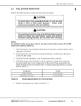
1
Solar Battery Charger
By
Christian Peter C. Antonio
Jian B. Madrona
A Design Report Submitted to the School of Electrical Engineering,
Electronics and Communication Engineering, and Computer
Engineering in Partial Fulfillment of the Requirements for the Degree
Bachelor of Science in Computer Engineering
Mapua Institute of Technology
September 2008
1
Chapter 1
DESIGN BACKGROUND AND INTRODUCTION
Introduction
One of the least tapped sources of energy is the solar energy. Solar
energy is free and does not create harmful by-products. The Philippines is one of
best places to harness this form of energy because it is located near the equator.
Being a tropical country, exploiting the powers of the sun is very advantageous
for the people. The team would like to use this form of energy by transforming it
into electricity that would be used by a particular device.
As of April 24, 2008, Meralco, as the largest electricity provider in the
Philippines, announced that it was raising its rates. (This was another factor why
the team conducted this research design. Aside from saving on their electric
consumption to keep their electric bill low, people can save further by using solar
energy to charge their devices. This alternate energy source is even free of
charge. Solar cell is a key device that converts the light energy into electrical
energy in photovoltaic energy conversion. This was the reason why the research
team chose solar cell to be the main part of the prototype.
Mobile devices (and other devices such MP3 Player and MP4 Player) are
everywhere but oftenly, people find themselves lacking battery supply for their
gadgets. This usually happens when an electrical battery charger is nowhere to
2
be found, or there is no available electrical outlet where a low battery can be
recharged. (Soga, 2006).
Review of Related Literature
The Technology of Flat Plate Collectors
Of all the applications of solar energy, the use of flat plate collectors in
heating is the most practical. The solar liquid heater was invented by H.B.
Saussure during the second half of the 17th century; Herschel (1837) and Tellier
(1885) also experimented on solar water heaters. Even in earlier times, the
indigenous people of Africa, the Arab countries, Australia, China, India and
Pakistan used their ingenuity in heating water by placing a specially shaped
copper pot filled with water in the sun during the winter. Air heaters, however,
are of recent invention. K.W. Miller introduced the overlapped glass plate air
heater in 1943. Nowadays, it is cheaper to use solar water heaters for domestic
appliances, and as such they are used all over the world.
From 1960 onwards, flat plate collectors have had the biggest share in
research and development. This paper outlines the capabilities and limitations of
such devices, with the intention of promoting the proper use of flat plate
collectors, especially in developing countries. (Dixon and Leslie, 1979).
3
Characteristics of the Components of Flat Plate Collectors
A flat plate collector normally consists of an absorber, which is made of
blackened metal – usually copper – and a grid of pipes soldered to the absorber.
The assembly is placed in a box with insulation at the back of the absorber and
one or two transparent covers at the top to allow sunlight in.
Material
Mineral wool (clay, fiberglass, rock)
Hair Felt
Granulated Cork
Re-granulated cork (0.474 cm particles)
Compressed cork
Straw
Sawdust
Vermiculite (granulated)
Polyurethane foam (rigid)
Polystyrene (expanded)
Approximate
Density
(kg/m3)
12-14
80
Thermal
Conductivity
(Wm-1˚C-1)
0.0332-0.0404
0.0389
120
30
0.0476
0.04471
136-176
10-13
13-240
128
24
16
0.0418-0.0462
0.0576
0.0649
0.0721
0.0245
0.0303
Table 1. Properties of Commonly Used Insulation Materials
The properties of commonly used insulation materials are shown in Table
1. Plastic materials, such as PVF, and fiberglass sheets, have been used in solar
heaters, but they are in general inferior to glass because they deteriorate with
time and at high temperatures. Moreover, ultraviolet radiation discolors them.
The plastic cover is, however, easier to handle than the glass cover.
4
The theoretical analysis for a flat plate collector is well established and
can be summarized in the equation: Qo=Qa – QL, where Qo is the power output,
Qa is the power absorbed by the collector, and QL is the power lost to the
surroundings. The value of Qa depends largely on the materials, of which the
collector is made, and its coating and the solar angle of incidence. (Dixon and
Leslie, 1979).
Practical Points
The following points should be noted with regard to the manufacture of flat plate
collectors:
a. poor adhesive is often used between the glass covers and the collector
box. This is because it is preferable to let the pressure inside the collector
gap be atmospheric so as to reduce convection and air conduction losses.
This can only be achieved by not making the covers airtight. However, as
a result, dust and moisture penetrate the collector and erode the surface
of the absorber plate;
b. insulation materials may contain moisture before they are used in the
collector. As the collector gets hot, this moisture evaporates and
condenses on the inside surface of the glass, and affects the incident
radiation. It also corrodes the absorber plate;
c. allowance must be made for glass expansion, and the edges of the
collector must be beveled so that no rainwater collects on them;
5
d. the collector should not be used without any liquid inside it. Otherwise,
the high interior temperature generated will cause abnormal expansion
that can distort or break the covers;
e. in order to alleviate problems due to the freezing of water in tubes, a
water/ethylene glycol solution can be used;
f. the maximum area of a collector should be 2m2 ; and
g. to reduce the amount of infrared radiation escaping from the collector,
specially coated glass covers can be used. This coating should be on the
inside of the covers. (Dixon and Leslie, 1979).
CdS Thin Film Solar Cell
The CdS thin film solar cell is photovoltaic device made from a thin
polycrystalline film of semiconducting CdS which is deposited on a suitable
substrate. The essential features are: a substrate., a CdS layer, a barrier layer,
and contacts. The substrate may be conducting or insulating, thin and flexible or
thick and inflexible, transparent or opaque. The CdS layer is usually formed by
vacuum deposition and is generally but not necessarily between about 10 and 30
mhu in thickness with an average grain diameter on the same order. The grains
are normally disposed with the optical axis approximately perpendicular to the
substrate with “fibre axis” orientation. The CdS film is invariably n-type
semiconducting with resistivity usually within about one order of 10 ohm-cm, and
hall mobility in the plane of the film within about one order of 10 cm2 / V-sec.
(Shirland, 1966).
6
Film Cell Construction
1. Backwall cells
Backwall CdS film cells can be made using either opaque or transparent
substrates. With an opaque substrate, the rectifying electrode or the barrier layer
must be deposited first and the CdS film is deposited as an over layer. A ceramic
substrate is coated with a layer of Cu2S and the CdS film evaporated onto it and
contracted with a collector electrode at one edge. A sheet of copper is used as a
substrate which may be oxidized or sulfided prior to CdS deposition. In c, the
rectifying and ohmic electrodes are deposited as alternate stripes on a glass
substrate and overcoated with the CdS. Even though the substrate may be
transparent, it does not need to be , and hence, this is basically the same.
Cells of this type have all been relatively inefficient and have series
resistance effects. While they may have been present, they do not appear to
have been the major reason. It appears that the formation of a junction or
barrier to CdS by the use of “dry” methods usually yields a poor cell.
2. Frontwall cells
The first frontwall CdS film solar cell was probably made by NADJAKOV,
though it was probably not recognized as a frontwall cell
at the time.
Photovoltaic action probably occurred only within about a micron’s distance from
the rectifying metal electrode contact. Thus, the active area was exceedingly
small and accounts for the very low currents obtained.
7
The first frontwall cells in the 1% efficiency range were constructed as
shown in b, with a more or less continuous thin Cu2S layer on the CdS contacted
by conductive paint electrode stripes spaced about 3-4mm apart as mentioned
earlier.
3. Frontwall-backwall combination cell
If suitable transparent conducting electrodes are used, it is evident that
the cell could be made in such a manner that it could be illuminated from either
or both directions. The first work along these lines was evidently done by
RAVICH at Itek Laboratories. His cell structured was like that shown in Figure 6A.
Th CdS film was formed onto SnO2 coated glass substrates, and the barrier layer
was contacted with an evaporated gold electrode.
Ravich also tried a comb-like metallic grid, photoformed in place on the
substrate, instead of the SnO2 layer. This was, however, not very satisfactory,
because it could be made with only about 50% of the substrate surface
uncovered. The gold film evaporated onto the barrier is compatible with the
barrier electrically, but unfortunately, it is not very conductive unless it is made
thicker, in which case it is not very transparent. This cell construction is severely
limited in output by series resistance. (Shirland, 1966).
Performance
1. Power Output
2. Voltage Output
8
3. Current Output
4. Effect of Illumination Intensity
5. Time response
6. Effect of temperature
7. Spectral response
8. Stability
Conclusions and Future Possibilities
The CdS thin film solar cells described in this paper have not “flown” in
space, and they have not been made in production. There is further development
and engineering work required in order to qualify them for space and to develop
the fabrication processes for mass production.
More than 800 cells have been made of the 50 cm2 area size in the
laboratory having conversion efficiencies greater than 4%. These cells have been
shown to be inherently stable, thin, flexible, and relatively straightforward to
fabricate. There is nothing apparent in the materials required or in the cell design
or fabrication methods to indicate that they could not be made in real mass
production at very low costs. It is appropriate therefore that we consider the
possibilities for future improvements and explore potential applications for them.
(Shirland, 1966).
Conceptual Framework
Input
Process
Output
Solar Panel
Device Charging
Internal Battery
Switch
Solar Energy
Microcontroller
Voltage
Internal Battery
charging
9
Figure 1. Conceptual Framework of the System
Figure 1 shows the conceptual framework of the system. It shows the
inputs that are to be processed to come up with the desired output. The two
inputs are the switch and the solar energy. The switch is used for turning the
prototype design ON or OFF. The solar energy, on the other hand is the source
of energy for this research design. It is used to charge either the device or the
internal battery. With the use of these elements, the design prototype will
activate and is ready to use.
During the process, the solar panel will collect the solar energy and will
convert it to electrical energy. The electrical energy will be used to charge either
the internal battery or the device, or both. If the user prefers to use the battery
as the source for charging, the stored power from the battery will transfer to the
device. If the user prefers to use the energy from the solar panel, the converted
solar energy will be transferred directly to the device. During charging, either the
user prefer to use the internal battery or the solar panel as the source, the
microcontroller will respond and will be used as the voltmeter that will read the
voltage being supplied to the device. The potentiometer will serve as the voltage
selector. Using the switch, the user can select the voltage supply either fixed or
varied.
10
As the output, the seven-segment will display the voltage read by the
voltmeter. The processed energy will charge the device. If the user prefers to
charge the internal battery alone, a LED will activate; this indicates that the
internal battery is being charged.
In case the user prefers to use the internal battery or the solar panel as
the source yet there is no enough energy, definitely, the device will not charge.
Statement of the Problem
As of today, the most prominent problem that the country faces is the
price increase of basic necessities such as petroleum, water, food and electricity.
With the price increase, people resort to alternatives to make the cost of living
cheaper. Given this premise, the research team desired to help people cheapen
their cost of living by reintroducing solar energy as an alternative to electrical
energy in some cases.
Solar energy is a great alternative for power because it is renewable and
free. With the device that the researcher created, solar energy could now
partially resolve the problem in electricity usage.
Objective
The objective of this project design was to create a prototype of a solar
battery charger, preferably for AA rechargeable batteries, and some mobile
devices. A USB port adaptor was included in order to charge mobile devices such
11
as Nokia cellphones, MP3 players, and other devices utilizing the same voltage
range and ports. Due to the uncertainty of receiving full charging capacity from
the sun, an internal battery would be charged to supply additional emergency
voltage. Using a PIC microcontroller, the team would designed a voltmeter. The
voltmeter would be used to indicate the voltage output of the charger to the user.
Together with a voltage regulator, this would prevent supplying the load with
incorrect voltage.
Utilizing solar panels with a charger would make the voltmeter very
versatile and mobile device. It can be charged almost anywhere for as long as it
is exposed to direct sunlight over a period of time. If under less optimal weather
condition, internal batteries will still ensure that the charging continues.
The research team worked on this study for the benefit of mobile
appliance owners. The study was meant to supply the owners with information
that could benefit them. The study would provide them with an almost unlimited
source of energy for their electronic devices even during less sunny days or
under bad weather condition.
Significance of the Design
This design would help people, especially Nokia cell phone users, and the
users of other devices utilizing the same voltage range and ports, to save
money at the same time utilize energy that is nature-friendly. As students, this
12
project design is very important because through this study, the team members
were able to apply and practice their technical skills and accumulated
knowledge and learning’s. This prototype was also created to minimize the
expenses of the people especially during these times when the price of
electricity keeps on soaring.
Scope and Delimitation
The study was concerned with the development of a design called Solar
Battery Charger that would serve as alternative to or replacement for the electric
battery charger available in the market. The research study set the scope and
delimitation as follows:
The scope:
1. The prototype is able to charge batteries that require 1V-17V recharge.
2. Devices such as cell phone, MP3 and PDAs are the devices that solar battery
charger can charge.
3. A voltmeter is also attached to the said device to monitor the voltage that is
being supplied to the system.
4. Internal battery is included to allow the unit to store energy that is very useful
at times when there is less or no solar energy due to charging weather condition.
5. LED indicators are included as to show if there is voltage running in the
system and if the internal battery is charging.
The delimitation:
13
1. It can only charge devices like cell phone, MP3 player, MP4 player and others
devices that require voltage range from 1V-17V to charge.
2. It only charge internal battery if the solar panel provides 12V or higher.
3. Chargers that are suitable for cigarette phone jack are the only ports that the
solar battery charger can provide.
4. Solar battery charger cannot be used during night time unless the internal
battery is fully charged to support the voltage needed by the device to recharge.
Definition of Terms
Adaptor is a device connecting electrical appliances to a single socket.
(Oxford, 2007)
Battery a device containing an electrical cell or cells used as a source of power.
(Oxford, 2007)
Capacitor is a passive element designed to store energy in its electric field, the
most common electrical components. It is consisted of two conducting plates
separated by an insulator (or dielectric). It is an open circuit to dc used
extensively in electronics, communications, computer, and power systems.
(Alexander and Sadiku, 2003)
Cellphone is a mobile phone. (Oxford, 2007)
Charge is meant to store electrical energy in a battery; electricity existing
naturally in a substance. (Oxford, 2007)
Charger is a device for charging a battery. (Oxford, 2007)
14
Heatsink is an environment or object that absorbs and dissipates heat from
another object using thermal contact (either direct or radiant). Heat sinks are
used in a wide range of applications wherever efficient heat dissipation is
required. (Podbieksi, 1999)
LED (Light Emitting Diode) is a type of diode that emits light when there is
forward current. (Floyd, 2002)
PIC Microcontroller (Programmable Integrated Circuit) is a family of
Harvard architecture microcontrollers made by Microchip Technology; it is
derived from the PIC1640 originally developed by General Instrument's
Microelectronics Division. (Podbieksi, 1999)
Photovoltaic module is a packaged interconnected assembly of photovoltaic
cells. (Podbieksi, 1999)
Potentiometer is a three-terminal device that operates on the principle of
voltage division. It is essentially an adjustable voltage divider. As a voltage
regulator, it is used as a volume or level control on radios, TVs and other
devices. (Alexander and Sadiku, 2003)
Rectifier Diode is a semiconductor device that converts ac into pulsating dc;
one part of a power supply. (Floyd, 2002)
Resistor is the simplest passive element. It is a device that has the ability to
resist the flow of electric current that is measured in ohms. It is usually made
from metallic alloys and carbon compounds. (Alexander and Sadiku, 2003)
Solar is the energy of the sun. (Podbieksi, 1999)
15
Solar Cell is a device that converts solar energy into electricity by the
photovoltaic effect. (Podbieksi, 1999)
Solar Energy refers to the utilization of the radiant energy from the sun.
(Podbieksi, 1999)
Toggle Switch is a class of electrical switches that are actuated by a
mechanical lever, handle, or rocking mechanism. (Podbieksi, 1999)
Transistor is a semiconductive device used for amplification and switching
applications. (Floyd, 2002)
Voltage Regulator keeps a constant dc output voltage when the input or load
varies within limits. (Podbieksi, 1999)
Voltmeter is an instrument for measuring voltage. (Podbieksi, 1999)
16
Chapter 2
DESIGN METHODOLOGY AND PROCEDURE
Design Methodology
This research used structural methodology. Structural methodology is a
process that follows the design procedure. In this case, the research was started
by determining the problem. It was followed by reviewing related literature and
studies and conceptualizing and developing the design. Figure 2 (on the next
page) shows the procedure in developing the design. On the succeeding pages,
Figure 3 shows the block diagram of the solar battery charger and Figure 5
shows the detailed functions of the solar battery charger.
Design Procedure
Figure 2 shows how the research study was done. The first step was to
identify the problem that was how to charge cell phone and other devices with
the same voltage range using the solar energy. After identifying the problem,
relevant data were gathered to support the study, such as related literature and
studies. These literature and studies were revised. Information useful to the
design was recorded. When the data needed in the study were already
substantial, possible solution to the problem was outlined. This was followed by
gathering information about the materials and components to be used and
checked again as to its usefulness and suitability as far as the design was
concerned. When all the needed materials and components were gathered, the
development and creation of the design started.
17
Figure 2. Design Procedure
18
Design Procedure for Actual Design
The design was started by researching on and finding the materials
components suitable for the creation of the prototype. The appropriate products
to be used were identified through data sheets researched on other related
documents.
The detailed steps in constructing the research design are as follows:
1. Develop the PCB layout of the solar battery charger using the PCB Wizard
software. Print the PCB layout in acetate.
2. Cut the printed circuit board in 3”x3.5”.
3. Place the printed acetate (with PCB layout) at the top of printed circuit board.
Expose it to UV light for about 30 seconds up to 1 minute.
4. Dissolve right amount of developer in water and place the exposed printed
circuit board etch the circuit layout.
5. When the circuit layout is clear and visible, wash the printed circuit board with
water to avoid continuous etching.
6. Place the etched printed circuit board to ferric chloride to dissolve unwanted
copper in the board by shaking the container. When all unwanted copper is
removed, wash the board with water and dry.
7. Test all the connections of copper layout using the VOM.
8. When all connections are tested and found correct, drill the board according to
the placement of the components.
9. Mount all the components to the board except for the microcontroller.
19
10. Solder all components to the board. Make sure that the lead is big enough to
hold and connect the component to the board, but not too big to avoid
unwanted connection.
11. Test the function of the prototype.
12. Create a program for the specific function of the microcontroller which is
voltmeter. Using assembly language, encode the program and with MPASM,
convert the program to machine code.
13. Burn the code to the microcontroller.
14. Place the microcontroller to the board.
15. Drill the plastic case and place other components that are supposed to be
expose such as the potentiometer, three-digit seven-segment display,
cigarette phone jack, toggle switches, and the LED indicator.
16. Solder all remaining connections.
17. Test and troubleshoot the prototype.
The solar battery charger has built-in voltmeter. The solar panel was
designed to be detachable to make the prototype easy to carry. The solar battery
charger has two switches; one that selects the source for charging either solar
panel or internal battery, and the other that selects if the voltage being supplied
is fixed or variable. The solar battery was equipped with 7805 voltage regulator
that could control the flow of voltage being supplied to the device. The PIC
microcontroller was used as the voltmeter of the system. It could detect the
20
voltage being supplied and could display its value by the use of 3-digit 7segment display.
The prototype circuit was created for the whole design and was tested.
The microcontroller was programmed using assembly language. The program
was encoded through serial programming and compiled it using the MPASM
compiler that is downloadable and free. After compiling, the machine code was
burned to the PIC16F877. Testing and debugging for both programs and
electronic circuit were done afterwards. Circuit layout was created by
photosynthesizing. The design was completed by fitting the components inside
the casing. The solar battery charger was built by following the circuit diagram in
Appendix A.
Hardware Design
The whole prototype was basically powered by the solar energy that was
collected and converted into electrical energy by the solar panel. Once the solar
panel collected enough energy to charge the internal battery, the battery could
be used as the source to charge the device. The battery could provide up to 12V
to charge a device. on the other hand, the device could also charge using the
solar panel. The solar panel could provide up to 17.3 V depending on the
intensity of sunlight.
21
The voltage regulator would controlled the voltage entering the device.
The voltage rate would be read by the microcontroller and would act as the
voltmeter that would display the voltage reading through seven segment displays.
Figure 3. Block Diagram of the Hardware Design
22
List of Materials
Table 2. List of Materials
23
Hardware Component
The solar battery charger alone is basically composed of solar panel, diode,
internal battery, capacitor, switch, voltage regulator, potentiometer and cigarette
phone jack. The solar panel collects solar energy and converts it to electric
energy. A diode is placed after the solar panel to avoid feedback effect of the
electric charge. Feedback effect may happen once the charge of internal battery
is greater than the energy that the solar panel is providing. The internal battery
is placed to serve as storage and source of energy. Capacitors are used to check
if the energy flowing to the system is DC or AC. Switches are used to switch ON
or switch OFF the prototype and are also used to select the function of the
charger, select panel or internal battery as a source, and select if the voltage
produced can be varied or fixed. Once the user prefer to use the charger with a
specific voltage rate, that is the time the voltage regulator is used, thru the help
of the potentiometer. Finally the cigarette phone jack is used as the outlet for
charger that the user prefers to use.
Aside from the charger, the prototype also has built-in voltmeter. The
voltmeter
is
basically
composed
of
array
resistors,
crystal
capacitor,
microcontroller and the 7-segemnt-display. The array resistors convert the ac to
dc. The crystal defines the operating frequency of the microcontroller. The
microcontroller processes the inputs from the array resistors and crystal. The
output will be displayed using the 7-segment-display.
24
Circuit Design
Figure 4 shows the circuit diagram of the whole prototype design.
Figure 4. Schematic Diagram of Solar Battery Charger
The solar panel that collects and converts the solar energy to electrical
energy can be detached from the system. This is done to make the prototype
easy to carry. The prototype has two switches: one is for the source selector
and the other is for the voltage selector, whether it is fixed or variable. If the
25
user prefers to use the solar panel as its source for charging, the first switch
should be turned off (open) so that the battery is not connected to the system.
The solar panel must collect enough solar energy to be able to charge a certain
device. The user still has the option whether he wants to use fixed value of
voltage from the solar panel or vary it according to his requirements. The second
switch is used to connect the system to the voltage regulator that is used to vary
the voltage being supplied to the device. If the user prefers to use the internal
battery, the first switch should be turned on (close) to connect the battery to the
system. The device cannot be charged if the internal battery has no enough
energy. Just like the solar panel as a source, the user still has the option whether
he wants to use fixed value of voltage from the solar panel or vary it according
to his requirements.
Basically,
the
solar
battery
charger
can
function
without
the
microcontroller. The microcontroller functions as the voltmeter for the system. It
detects the voltage that is being supplied to the device. The electric energy as
the input is converted in binary code that is done inside the microcontroller and
the program will manage how the data will be arranged to have the expected
result or display.
26
Hardware Implementation
Upon completing the research study, the team designed the prototype;
carefully chose devices needed to implement the prototype. After completing the
prototype, the members troubleshot and tested the design. They used different
cell phone units to charge using the solar battery charger. MP3, MP4, and iPod
were also used to test the charger. All units were successfully charged.
Software Design
The program for the microcontroller was meant just for the built-in
voltmeter that could be found in the prototype. The program was created using
assembly language programming, a low-level language that implements numeric
machine code and other constants needed to program computer architecture.
Actually the PIC microcontroller could be program using other languages but it is
only assembly language that has the free-downloadable compiler available in the
internet. The compiler, which is the MPASM, is already available in the internet
provided by the manufacturer of the Microchip Technology Inc. for its
microcontroller users. The microcontroller has its built-in converter that served
very useful in this research design.
The on-chip debugger that was utilized worked as a special hardware and
software for the PIC Microcontroller. The PIC Microcontroller that was used
design contained a special on-chip logic supporting debugging functionality and
provided In-Circuit Serial Programming capabilities.
27
The machine code, that was the assembly language compiled using
MPASM, was burned to the microcontroller and the microcontroller was attached
to the system of the design and it functioned as the built-in voltmeter.
Software Component
Basically, the assembly language and MPASM were used for programming
the microcontroller. The design team considered the compiler first before the
language because there were so many compilers, but not all of them were
available in market, furthermore, it was deemed wise to use a compile that was
free of change. Since the MPASM is free of charge and downloadable, the
members decided to use assembly language, since assembly is the language that
the MPASM compiles. After programming, the program was compiled to machine
language and the machine code was burned to the microcontroller.
System Flowchart
Figure 5 shows the system flowchart of the solar battery charger. The
basic function of this prototype is to charge a device, such as cell phone and MP3.
To start, the prototype must be turned ON. The user has the option if he wants
to charge the device directly from the internal battery or the solar panel.
Whether the user chooses solar panel or the internal battery as the source for
charging the device, either of the sources must have enough energy to charge
the device. In charging, the user still has the option if he wants to have fixed or
variable voltage that will be supplied to the device.
28
Figure 5. System Flowchart of Solar Battery Charger
29
Prototype Development
Figure 6. Actual Photo of Solar Battery Charger
Figure 6 shows the actual appearance of the solar battery charger. The
prototype that the group developed is an actual size prototype. All components
were carefully chosen to produce an efficient prototype. From researching,
designing, developing up to testing, the group carefully gathered data and
implemented the design accordingly. Other actual photos of the prototype are
presented on the Appendix E.
30
Chapter 3
TESTING, PRESENTATION, AND INTERPRETATION OF DATA
The Solar Battery Charger was tested using VOM. Although the research
design has a built-in voltmeter, this was done to assure the reliability and
efficiency of the prototype. Since there are four functions that the prototype can
provide, there were also four testing done; one was having solar panel as source
with fixed value of voltage supply; two is having solar panel as source with
variable value of voltage supply; three is having internal battery as source with
fixed value of voltage supply; and four is having internal battery as source with
variable value of voltage supply.
The following steps were done to come up with the results:
1. To get the voltage that was collected by the solar panel, tap the VOM was
tapped directly to the solar panel connector. The VOM reading was recorded.
2. To get the value for Built-in Voltmeter Reading, switch the regulator switch
was switched on to bypass to get the fixed value and the reading of the built-in
voltmeter was examined.
3. The voltmeter was tapped to the cigarette phone jack to get the voltage being
supplied by the system to the device. The result was recorded on the voltmeter
reading column.
4. To get the voltage that was supplied by the internal battery, tap the VOM was
tapped directly to the internal battery connector. The VOM reading was
recorded.
31
5. To get the value for Built-in Voltmeter Reading, the regulator switch was
switched ON to regulate. The value was made varied then step 3 to 5 was
repeated for every voltage reading of the built-in voltmeter.
Built-in Voltmeter
Reading
Voltmeter Reading
24.2
17.5V
Using Voltmeter
Directly to the Solar
Panel
25.5V
Table 3. Solar Panel as Source with Fix Value of Voltage Supply
Table 3, presents the built-in voltmeter which displays 24.2V that is
definitely high compared to the voltmeter reading that is 17.5V. This result
occurred because voltage entering from the solar panel was also consumed by
the other components of the system.
Table 4, on the next page presents the results when the group used the
voltage regulator to monitor the voltage being supply to the system and device.
As expected, there was a voltage drop and as the voltage regulator increased its
voltage supply, the voltage drop also increased. Comparatively, the voltage
reading of built-in-voltmeter was higher than the reading of the voltmeter used
for testing. Due to voltage drop that was stated above.
32
Built-in Voltmeter
Reading
Voltmeter Reading
1V
2V
3V
4V
5V
6V
7V
8V
9V
10V
11V
12V
13V
14V
15V
16V
17V
17V
17V
17V
17V
17V
17V
17V
17V
17V
1V
1.2V
1.4V
1.6V
1.9V
2.2V
2.7V
3V
3.3V
3.7V
4.2V
4.5V
4.7V
5V
6V
7.8V
8.7V
9.2V
10V
9.3V
8.7V
9.7V
10.3V
8.6V
9.5V
8.9V
Using Voltmeter
Directly to the Solar
Panel
23.9V
24.6V
23.9V
24.9V
24.6V
24.5V
23.7V
25.5V
25.3V
24.9V
24.5V
24.5V
23.9V
23.4V
23.2V
24.9V
24.9V
25.1V
25.1V
25.5V
23.6V
23.7V
24V
24.6V
24.3V
24.9V
Table 4. Solar Panel as Source with Variable Value of Voltage Supply
33
Built-in Voltmeter
Reading
Voltmeter Reading
7.8V
3.8V
Using Voltmeter
Directly to the
Internal Battery
8.6V
Table 5. Internal Battery as Source with Fix Value of Voltage Supply
Just like Table 3, Table 5 shows the difference between the reading of
built-in VOM and voltmeter and the actual voltage being supplied by the internal
battery. Still, the built-in voltmeter displayed higher value that the actual
voltmeter used. This result occurred because voltage entering from the solar
panel was also consumed by the other components of the system.
Built-in Voltmeter
Reading
Voltmeter Reading
1V
2V
3V
4V
5V
6V
7V
8V
9V
1.2V
1.2V
1.5V
2.1V
2.6V
2.9V
2.8V
2.9V
3.5V
Using Voltmeter
Directly to the
Internal Battery
4.7V
4.7V
4.7V
4.7V
4.7V
4.7V
4.7V
4.7V
4.7V
Table 6. Internal Battery as Source with Variable Value of Voltage
Supply
34
Table 3, 4, 5, and 6 show the results of the testing the research design
with voltmeter. As seen in Figure 4, which is the schematic diagram of the Solar
Battery Charger, the voltage that was being sensed by the microcontroller,
passed through the microcontroller itself and the two LED specifically the
microcontroller that used 5V, at most, before it operated. Also the LED display
use 2V to activate, since the system has 2 LED, which is equal to 4V. All in all,
there was 9V, at most, that were used by the system before it was useD by the
device to charge. The same reason applied to other table. The difference
between the built-in voltmeter and voltmeter readings was not more than 9V.
Noticeably, the value of the voltmeter reading that was directly connected
to the solar panel varied from time to time. It was because the solar panel could
not collect constant solar energy that was converted to electric energy. Those
values have positive or negative 5% accuracy difference.
Table 7 shows the ampere that the solar battery charger can provide at a
given time. Based on the table, from six in the morning, where the sun starts to
provide solar energy, the ampere being supplied by the solar battery charger
started to increase. From 290mA at six in the morning it increased to 380mA at
one in the afternoon. 380mA is the maximum ampere that the solar battery
charger can provide. After one in the afternoon, the ampere being supplied by
the charger started to decrease.
35
Time
Amperes produced by the Solar Battery Charger
6:00 AM
7:00 AM
8:00 AM
9:00 AM
10:00 AM
11:00 AM
12:00 PM
1:00 PM
2:00 PM
3:00 PM
4:00 PM
5:00 PM
6:00 PM
290
300
310
320
340
350
360
380
370
350
340
310
300
mA
mA
mA
mA
mA
mA
mA
mA
mA
mA
mA
mA
mA
Table 7. Amperes Produced by the Solar Battery Charger in a Given
Time
With the given information from Table 7, it was learned that the minimum
ampere that the charger could provide was 290mA and the maximum was
380mA. The data were utilized to come up with Table 8 and Table 9. As
presented in Table 7, at six o’clock in the morning, the solar battery charger
could provide 290mA which is the minimum supply in the morning whereas at
one in the afternoon, the solar charger could provide up to 380mA supply which
was the maximum supply. It can be concluded therefore that one o’clock is the
best time to use the solar battery charger. However, the users are encouraged to
utilize the solar battery charger anytime. Table 8 shows the battery charging
hours of any device with 290mA supply and Table 9 shows the battery charging
hours of any device with 380mA supply. As observed, any device that used
36
380mA as supply charged faster than with 290mA supply. The group had the
option to use rapid charger on Nokia battery only. As expected, the rapid charger
unit charged faster than the ordinary charger unit.
Device / Battery Type
Ni-Mh AA
Nokia BL-5C
Nokia BL-4C
Nokia BL-4C
Noka6015i
Nokia BLD-3
Nokia3285
Nokia BLS-2N
Nokia BLB-2
Nokia BLB-3
Nokia BLC-2
Nokia BMC-2
Nokia BMC-3
LG LGLP-AGKM
LG LGLI-AGKL
HTC Touch XV6900
HTC BTR6900
HTC BTE6900
Ipod battery (60GB)
Ipod battery (30GB)
Apple Ipod 4th Gen
Apple Ipod 3rd Gen
Apple Ipod 1st and 2nd Gen mini series
Apple Ipod 1st and 2nd Gen
Asus MyPal PDA Battery (3.7V)
Asus PDA Battery (3.7)
LCD MP3 player 1GB mini pocket size
Capacity
mAH
2400
600
600
720
950
720
550
900
840
1020
950
1020
2280
800
1200
900
1100
1880
700
550
950
600
400
1600
1300
1200
Lithium
Time in hrs Capacity
/290mA
Ordinary
Charger
8h 15m
2h
2h
2h 30m
3h 15m
2h 30m
2h
3h
2h 50m
3h 30m
3h 30m
3h 30m
8h
2h 45m
4h 10m
3h 10m
3h 45m
6h 30m
2h 30m
1h 50m
3h 30m
2h
1h 30m
5h 30m
4h 30m
4h 10m
5h
Rapid
Charger
4h
1h
1h
1h 20m
2h
1h 20m
1h
1h 15m
1h 45m
2h 10m
2h
2h 35m
3h 40m
*
*
*
*
*
*
*
*
*
*
*
*
*
*
Table 8. Battery Charging Hours with 290mA Supply
37
Device / Battery Type
Ni-Mh AA
Nokia BL-5C
Nokia BL-4C
Nokia BL-4C
Noka6015i
Nokia BLD-3
Nokia3285
Nokia BLS-2N
Nokia BLB-2
Nokia BLB-3
Nokia BLC-2
Nokia BMC-2
Nokia BMC-3
LG LGLP-AGKM
LG LGLI-AGKL
HTC Touch XV6900
HTC BTR6900
HTC BTE6900
Ipod battery (60GB)
Ipod battery (30GB)
Apple Ipod 4th Gen
Apple Ipod 3rd Gen
Apple Ipod 1st and 2nd Gen mini series
Apple Ipod 1st and 2nd Gen
Asus MyPal PDA Battery (3.7V)
Asus PDA Battery (3.7)
LCD MP3 player 1GB mini pocket size
Capacity
mAH
2400
600
600
720
950
720
550
900
840
1020
950
1020
2280
800
1200
900
1100
1880
700
550
950
600
400
1600
1300
1200
Lithium
Time in hrs Capacity
/380mA
Ordinary
Charger
6h 15m
1h 30m
1h 30m
1h 45m
2h 30m
1h 45 m
1h 30m
2h 15m
2h 15m
2h 30m
2h 30m
2h 30m
6h
2h 10m
3h 10m
2h 15m
2h 45m
5h
1h 50m
1h 30m
2h 30m
1h 30m
1h
4h 15m
3h 30m
3hr10m
3hr
Rapid
Charger
3h 30m
50m
50m
55m
1h 20m
55m
50m
1h 10m
1h 10m
1h 20m
1h 20m
1h 20m
3h
*
*
*
*
*
*
*
*
*
*
*
*
*
*
Table 9. Battery Charging Hours with 380mA Supply
*No battery rapid charger available
38
Chapter 4
CONCLUSION AND RECOMMENDATION
Conclusion
A device that could charge AA battery and other devices such as cell
phone and MP3 player were created. The USB port adaptor was included to
provide port to other devices such as MP4, PDAs and other more devices utilizing
the same voltage range. The solar battery charger was able to charge the
internal battery that served as alternative source especially at times that there
was no available solar energy. It was learned that the designed device could
provide up to 25.5 V if charged directly from the solar panel and 13.5 V if
charged directly from the internal battery. Through testing, it was noted that the
voltage value being displayed by the built-in voltmeter was higher than the
actual voltage that was supplied to the device being charged. Specifically, there
was atmost 9V difference between the actual voltage being supplied and the
value being displayed by the built-in voltmeter. This 9V was the result of 5V
being used by the microcontroller and 4V being used by 2 LEDs.
Recommendation
Several improvements can be applied to the device to further enhance its
capabilities like calibrating the voltage entering the microcontroller to display the
exact value that is being supplied to the device. Other improvements can be
applied to the design for it to produce higher voltage rate so that it can also be
39
used as alternative energy source for laptops, computers, refrigerators and other
electronic or electric devices that are commonly used.
40
BIBLIOGRAPHY
Alexander, Charles K. and Sadiku, Matthew N.O. (2003). Fundamentals of
Electric Circuits, 2nd Edition, McGraw-Hill, New York.
Dixon, A.E. and Leslie, J.D. (1979). The Technology of Flat Plate Collectors.
Solar Energy Conversion, Pergamon Press, New York.
Floyd, Thomas L. (2002).Electronic Devices, 6th Edition, Pearson Education, Inc.,
publishing as Prentice Hall, New Jersey.
Oxford (2007). Soanes. Oxford English Mini Dictionary, 7th Edition, Oxford
University Press Inc., New York.
Podbielski, John (1999). Collins English Mini Dictionary. Second Edition.
HarperCollins Publishers, Great Britain.
Shirland, Fred A. (1966). Electronic Research Division. Clevite Corporation,
Cleveland, Ohio U.S.A.
Soga, Tetsuo (2006). Fundamentals of Solar Cell. Nanostructured Materials for
Solar Energy Conversion, Elsevier.
41
APPENDIX A
Circuit/Schematic Diagram
Figure 7. Block Diagram of Solar Battery Charger
Figure 8. PCB Layout of Solar Battery Charger
42
APPENDIX B
Source Code
;**********************************************************************
;
File SOLARBAT.ASM @4Mhz ceramic resonator
__config
processor
16F877
include
<P16F877.inc>
_HS_OSC & _WDT_OFF & _PWRTE_ON & _LVP_OFF & _BODEN_OFF &
_CP_ALL
;**********************************************************************
;
General Purpose RAM location: (STATUS-reg RP1/RP0: x__x
xxxx)
;
Bank_0: RP1/RP0 (00): 20H to 7FH (96 bytes)
;
Bank_1: RP1/RP0 (01): 20H to 6FH (80 bytes)
;
Bank_2: RP1/RP0 (10): 10H to 6FH (96 bytes)
;
Bank_3: RP1/RP0 (11): 10H to 6FH (96 bytes)
;
Note
: common access Bank_0 to Bank_3 : 70H to 7FH
;**********************************************************************
;
Variable Declaration
ADC0_HI
equ
H'40'
;
ADC0_LO
equ
H'41'
;
Hundred
equ
H'42'
;
Ten
equ
H'43'
;
Unit
equ
H'44'
;
Disp_Ctr
equ
H'45'
;
;
Temp1
equ
H'78'
; temporary variable.
Temp2
equ
H'79'
;
43
Temp3
equ
H'7A'
;
Temp4
equ
H'7B'
;
;**********************************************************************
;
Reset Vector Starts at Address 0x0000.
;**********************************************************************
org
0x0000
; start of reset vector.
goto
Initialize
;
;
org
0x0004
; start of interrupt service
goto
ISR_routine
;
routine.
;**********************************************************************
;
Initialization Routine.
;**********************************************************************
Initialize:
org
0x0008
;
clrf
TMR0
; Clear TMR0
clrf
INTCON
; Disable Interrupts and clear T0IF
bcf
STATUS,RP1
;
bsf
STATUS,RP0
; Select Bank 1
movlw B'11000011'
;
movwf OPTION_REG
;
;
movlw B'00001110'
; Set AN0 Left Justified
movwf ADCON1
;
movlw B'11111111'
;
movwf TRISA
; Port A. 11xx xxxx:TTL
0=Out 1=In
;
movlw B'00000000'
;
0=Out 1=In
44
movwf TRISB
; Port B. xxxx xxxx:TTL
;
movlw B'00000000'
;
0=Out 1=In
movwf TRISC
; Port C. xxxx xxxx:schmitt
;
movlw B'00000000'
;
0=Out 1=In
movwf TRISD
; Port D. xxxx xxxx:schmitt
;
movlw B'00000111'
;
0=Out 1=In
movwf TRISE
; Port E. xxxx xxxx:schmitt
;
bcf
STATUS,RP0
; Select Bank 0
;
call
Init_Var
;
;**********************************************************************
Main:
call
Display
;
call
Delay
;
goto
Main
;
;**********************************************************************
;
The Interrupt Service Routine.
;**********************************************************************
ISR_routine:
retfie
; Return from Interrupt.
;**********************************************************************
Seg_Table:
addwf
PCL,F
;
; afbgc.de
retlw B'00010100'
;0
retlw B'11010111'
;1
retlw B'01001100'
;2
45
retlw B'01000101'
;3
retlw B'10000111'
;4
retlw B'00100101'
;5
retlw B'00100100'
;6
retlw B'01010111'
;7
retlw B'00000100'
;8
retlw B'00000101'
;9
retlw B'11111111'
;A
retlw B'11111111'
;B
retlw B'11111111'
;C
retlw B'11111111'
;D
retlw B'11111111'
;E
retlw B'11111111'
;F
;
Init_Var:
clrf
PORTC
;
clrf
PORTB
;
bsf
PORTD,7
;
bsf
PORTD,6
;
bsf
PORTD,5
;
movlw
B'00000001'
; 00xx x001
movwf
ADCON0
; select AN0 to convert
clrf
ADC0_HI
;
clrf
ADC0_LO
;
clrf
Disp_Ctr
;
call
BIN2BCD
;
return
;
;**********************************************************************
Display:
bsf
PORTD,7
;
46
bsf
PORTD,6
;
bsf
PORTD,5
;
;
Disp_100:
Disp_100X:
movf
Disp_Ctr,W
;
sublw
D'2'
;
btfss
STATUS,Z
;
goto
Disp_100X
;
movf
Hundred,W
;
andlw
H'0F'
;
call
Seg_Table
;
movwf
PORTB
;
bcf
PORTD,7
;
nop
;
;
Disp_010:
Disp_010X:
movf
Disp_Ctr,W
;
sublw
D'1'
;
btfss
STATUS,Z
;
goto
Disp_010X
;
movf
Ten,W
;
andlw
H'0F'
;
call
Seg_Table
;
movwf
PORTB
;
bcf
PORTB,2
;
bcf
PORTD,6
;
nop
;
;
Disp_001:
movf
Disp_Ctr,W
;
sublw
D'0'
;
47
Disp_001X:
btfss
STATUS,Z
;
goto
Disp_001X
;
movf
Unit,W
;
andlw
H'0F'
;
call
Seg_Table
;
movwf
PORTB
;
bcf
PORTD,5
;
nop
;
;
incf
Disp_Ctr,F
;
movlw
D'3'
;
subwf
Disp_Ctr,W
;
btfss
STATUS,C
;
goto
DisplayX
;
clrf
Disp_Ctr
;
call
Read_ADC
;
movf
ADC0_HI,W
;
movwf
Temp2
;
call
BIN2BCD
;
;
DisplayX:
return
;
;**********************************************************************
Read_ADC:
btfsc
ADCON0,2
; Test if ADC conversion ?Done
goto
Read_ADCX
;
;
movf
ADRESH,W
; get A/D result
movwf
ADC0_HI
;
movlw
B'00000001'
;
48
movwf
ADCON0
; ensure A/D is active
;
Start_ADC:
bsf
ADCON0,2
; start A/D conversion
;
Read_ADCX:
return
;
;**********************************************************************
BIN2BCD:
clrf
Hundred
;
clrf
Ten
;
clrf
Unit
;
;
Inc_100:
movlw
D'100'
;
subwf
Temp2,W
;
btfss
STATUS,C
;
goto
Inc_010
;
movwf
Temp2
;
incf
Hundred,F
;
goto
Inc_100
;
;
Inc_010:
movlw
D'10'
;
subwf
Temp2,W
;
btfss
STATUS,C
;
goto
Inc_001
;
movwf
Temp2
;
incf
Ten,F
;
goto
Inc_010
;
;
Inc_001:
movf
Temp2,W
;
movwf
Unit
;
49
;
return
;
;**********************************************************************
Delay:
Dly_Loop:
movlw
D'250'
;
movwf
Temp1
;
decf
Temp1,F
;
movf
Temp1,W
;
btfss
STATUS,Z
;
goto
Dly_Loop
;
return
;
;**********************************************************************
end
;
;**********************************************************************
50
APPENDIX C
51
52
53
APPENDIX D
54
55
56
APPENDIX E
Actual Photos of Solar Battery Charger
57
58
59
60
APPENDIX F
User Manual of Solar Battery Charger
61
Solar Panel used to collect
and convert solar energy
Charging Using the Solar Panel
1. Connect the solar panel to the jack. Expose it to the sunlight.
2. Switch the source switch.
3. Switch the regulator switch according to your choice (the green indicator must
turn-on, this indicates that there is voltage being supplied to the system).
4. Connect the cellphone battery charger or any charger that is suitable to the
cigarette phone jack.
5. If you choose to regulate the voltage, adjust the voltage regulator according
to the voltage that is needed by the device, to maximize, to minimize.
6. Connect the device to the charger. Disconnect when battery is full.
NOTE: If the device is not charging, try to adjust the voltage regulator, or try to
expose the solar panel to a better place where it can gather more solar energy.
Charging Using the Internal Battery
1. Switch the source switch.
2. Follow procedure no. 3-6.
62
NOTE: Make sure that the battery has enough voltage to charge the device. To
check, switch the switch regulator to bypass and read the voltage that the
internal battery has using the built-in VOM display. If the internal battery has no
enough charge, follow the procedure below (Charging the Internal Battery Using
the Solar Panel) to charge it using the solar panel:
Charging the Internal Battery Using the Solar Panel
1. Connect the solar panel to the jack. Expose it to the sunlight.
2. Switch the source switch. This is done to make sure that the internal battery
is connected to the system.
3. Position the solar panel in an area where there is enough direct sunlight.
4. Notice if the red light is on to indicate.
5. To check the charge, switch the switch regulator to bypass and read the
voltage that the internal battery has using the built-in VOM display.
NOTE: If the battery is not charging (red light is off), it only means that the solar
energy being collected by the solar panel is not enough to produce 12V. Try to
expose the solar panel to better place where it can gather more solar energy.
63