1
UNIVERSAL MECHANISM 6.0
Development of Models
and Dynamic Analysis of
Tracked Vehicles
Getting started
2010
Basic principles of development of models of tracked vehicles and their dynamic are discussed.
Universal Mechanism 6.0
2
Getting started: UM Caterpillar
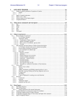
Contents
Getting started: development and dynamic analysis of tracked vehicles in UM ............................. 3
1. Development of TV model ................................................................................................... 4
1.1.
Prototype ...................................................................................................................... 4
1.2.
Creating new object and track subsystem ...................................................................... 5
1.3.
Track structure .............................................................................................................. 6
1.4.
Adding suspension ........................................................................................................ 7
1.5.
Adding sprocket.......................................................................................................... 10
1.6.
Adding idler ................................................................................................................ 12
1.7.
Adding track chain ...................................................................................................... 13
1.8.
Adding shock absorbers .............................................................................................. 14
1.9.
Development of full TV model ................................................................................... 17
1.9.1. Adding hull ........................................................................................................... 17
1.9.2. Coupling hull and track ......................................................................................... 19
1.9.3. Adding the second track ........................................................................................ 20
1.9.4. Correction of vertical TV position ......................................................................... 21
2. Simulation of TV dynamics ................................................................................................ 24
2.1.
General remarks.......................................................................................................... 24
2.2.
Auxiliary tests............................................................................................................. 25
2.2.1. Test: equilibrium ................................................................................................... 25
2.2.2. Track tension ........................................................................................................ 27
2.2.3. Vertical harmonic loading ..................................................................................... 30
2.2.4. Test: initial velocities ............................................................................................ 31
2.3.
Straight motion of TV ................................................................................................. 32
2.3.1. Motion on sinusoidal road profile .......................................................................... 32
2.3.2. Modeling of jump ................................................................................................. 34
References
Universal Mechanism 6.0
3
Getting started: UM Caterpillar
Getting started: development and dynamic analysis of
tracked vehicles in UM
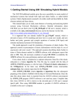
Fig. 1 Model of TV
This document helps the user to get experience in development of models and simulation of
tracked vehicle (TV) in UM. The model, which development is discussed, is shown in Fig. 1.
It is assumed that the user has already studied the document devoted to introduction in UM
1
(file gs_UM.pdf ) and can create and analyze simple models.
This document does not contain complete information about simulation of TV in UM. More
detailed information can be found in Chapter 18 of the user’s manual, file
18_UM_Caterpillar.pdf.
The ready TV model considered in this document is located in the directory
{Path to UM}\Samples\Tracked vehicle\gsTV
1
http://www.umlab.ru/download/50/rus/gs_um.pdf
Universal Mechanism 6.0
4
Getting started: UM Caterpillar
1. Development of TV model
1.1. Prototype
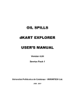
Fig. 2 Data on prototype of TV
A Russian light crawler transporter is considered as the prototype of the model. Fig. 2 shows
some geometric data related to the tracks [1].
We would remind that this document is developed to help the user in studying UM Caterpillar
module. That is why we will not follow the exact design data of the prototype.
Universal Mechanism 6.0
5
Getting started: UM Caterpillar
1.2. Creating new object and track subsystem
Fig. 3 Adding new subsystem “Caterpillar”
1) Run UMInput.exe and create a new UM object by File | New object menu command or by
the button on tool panel.
2) Save the model by the File | Save as command or by the
button.
3) Add a track as a subsystem of the Caterpillar type
· select the Subsystems item in the element list
· click the right mouse button on this item and select the Add element to group
“Subsystems” | Caterpillar, Fig. 3.
As a result, the Track wizard appears in the object inspector.
4) Rename the subsystem to Left track.
Universal Mechanism 6.0
6
Getting started: UM Caterpillar
1.3. Track structure
Fig. 4 Parameters of track structure
Open the Parameters | Structure tab of the wizard, Fig. 4.
1) The modeled TV has a torsion bar suspension with six road wheels. Each of the wheels is
described by a standard subsystem, Chapter 18, Sect. Torsion bar suspension. Thus, number six
must be set in the Suspension subsystems box.
2) The TV has no support rollers; zero value is set in the corresponding box.
3) Number of track links is 108.
Universal Mechanism 6.0
7
Getting started: UM Caterpillar
1.4. Adding suspension
Fig. 5 Uninitialized values of suspension geometry parameters
Open the Parameters | Suspension tab, Fig. 6.
1) As we have pointed out six suspension units (subsystems), the table of geometrical parameters
of suspension contains the same number of longitudinal coordinates of the subsystems
(Xc1…Xc6). Besides, the road wheel radius (R) and width (W) must be set in this table. All
parameters are in meters. The suspension unit type is specified on the same tab as
torsion_bar_wheel, i.e. the default value.
Fig. 6 Value of suspension geometry parameters for the MT-L transporter
Following the data in Fig. 2 fill in cells of the tab as in Fig. 6. Note, that the origin of SC0 in
the X-direction is located on the level of the sprocket center.
Fig. 7 First variant of suspension
2) Click the Generate button to create the suspension according to the specified parameters; the
suspension appears in the animation window, Fig. 7
Universal Mechanism 6.0
8
Getting started: UM Caterpillar
Fig. 8 Selected identifiers of torsion bar suspension
Fig. 9 Assignment of numeric values for identifiers in subsystems
3) Now some parameters of the suspension must be modified. Open the Identifiers | Suspension
tab of the wizard, Fig. 8. Set the length of the torsion arm 0.36m (the identifier l_road_arm). All
the suspension subsystems contain identifiers with the same name, a window appears in which the
user must check the subsystems, for which the identifier value will be changed by the new one,
Fig. 9. By default, the new value is assigned to all identifiers of the same name.
We will not change the default values of identifiers, which define the position of the
suspension in static state (alpha_stat) as well as the static and dynamic travel of wheels (f_stat,
f_dyn, Chapter 18, Sect. Torsion bar suspension).
Fig. 10 Road arm orientation
As it is shown in Fig. 2, five road arms has a backward orientation but the front one, which
has a forward orientation. So far, all arms in our model are oriented forward. The orientation is
defined by the identifier rear_arm=±1. The value +1 corresponds to the backward orientation. To
set the necessary values of this identifier in the subsystems, set rear_arm =+1 in the cell in Fig. 8
and press Enter. Uncheck the assignment of the new value in the lower row, Fig. 10. As a result,
orientation of five road arms will be changed, Fig. 11.
Universal Mechanism 6.0
9
Getting started: UM Caterpillar
Fig. 11 Suspension with modified parameters
Universal Mechanism 6.0
10
Getting started: UM Caterpillar
1.5. Adding sprocket
Fig. 12 Geometric parameters of sprocket
Fig. 13 Tooth profile
Open the Parameters | Sprocket tab, Fig. 12.
1) Assign a tooth profile by the built-in curve editor:
· open the editor by the
button, Fig. 13
· read the preliminary created file with profile
{Путь к UM}\bin\Caterpillar\Profiles\Sprocket1.spf
by the button.
2) Set number of teeth, t w / t t ratio and geometric parameter: width of the wheel, the vertical
and longitudinal coordinates of the wheel center, Fig. 12.
3) Use the
button to preview the sprocket, Fig. 14. Note the sprocket radius is computed
automatically by the link length, t w / t t ratio and number of teeth so that the final variant can
differ from the current one.
Universal Mechanism 6.0
11
Getting started: UM Caterpillar
Fig. 14 Sprocket preview
Fig. 15 Adding sprocket
4) Add the sprocket to the model by the Generate button, Fig. 15.
Universal Mechanism 6.0
12
Getting started: UM Caterpillar
1.6. Adding idler
Fig. 16 Parameters of idler
Open the Parameters | Idler tab, Fig. 16
1) Select a simplified model of the idler on a crank: idler_crank_simple.
2) Set geometrical parameters of the idler in meters as in Fig. 16: radius, width and coordinates
of the center.
3) Add the idle to the model by the Generate button, Fig. 17.
Fig. 17 Adding idler with tension device
Universal Mechanism 6.0
13
Getting started: UM Caterpillar
1.7. Adding track chain
Рис. 18 Tack chain parameters
Open the Parameters | Track tab, Fig. 18.
· Use tracklink_bushing joint type.
· Set track link length, which is evaluated by the program in the ‘Estimation of link length’
box.
· Click the Generate button, Fig. 19.
Fig. 19 Adding track chain
Universal Mechanism 6.0
14
Getting started: UM Caterpillar
1.8. Adding shock absorbers
Fig. 20 Button for editing the subsystem
Description of process.
1) Use the Edit subsystem button to open a window with description of the track, Fig. 20.
Fig. 21 Menu command for adding an element from file
2) Add a shock absorber model from the UM database by the Edit | Read from file
command, Fig. 21. Select the file
{Path to UM}\bin\Caterpillar\Dampers\Damper1.
Fig. 22 Image and nonlinear characteristics of shock absorber
Universal Mechanism 6.0
15
Getting started: UM Caterpillar
Fig. 23 Shock absorbers characteristics form [1]
The file contains the description of a nonlinear shock absorber as well as its image, Fig. 22. The
force vs. velocity characteristics of the element is similar to one of that in [1], Fig. 23.
Fig. 24 Assignment of bodies and coordinates
Rename the element; assign bodies and coordinates of attachment points, Fig. 24 left. Note
that the side_key is used for the lateral coordinate to change the coordinate sign in case of the left
and right tracks.
To add the rear shock absorber, copy the front on by the
button, rename it, change the
second body and coordinates of attachment points as in Fig. 24 right.
Fig. 25 Model of track with shock absorbers
Universal Mechanism 6.0
16
Getting started: UM Caterpillar
To finish the process of adding the shock absorbers, close the subsystem by the Accept
button, Fig. 25.
Save the ready mode of the left track to file.
Remark. We have developed a simplified track model. Several elements are not included in
the model.
Universal Mechanism 6.0
17
Getting started: UM Caterpillar
1.9. Development of full TV model
To finish the model development, we must add a hull and the second track.
Fig. 26 Hull image
1.9.1. Adding hull
1) Read an image of the hull from the UM database, Fig. 26 by the Edit | Read from file
command, select the file
{Path to UM}\bin\Caterpillar\Profiles\Hull1.img
Fig. 27 Adding a body
2) Add a body to the model:
· select the Bodies item of the element list, Fig.27;
·
·
create a new body by the
button in the inspector;
set a name, image and inertia parameters; mass, moments of inertia relative to central
axes, coordinates of center of mass (gravity).
Universal Mechanism 6.0
18
Getting started: UM Caterpillar
Fig. 28 Example of hull inertial parameters
It is recommended to parameterize the inertia parameters like in Fig. 27. An example of
numeric values of inertia parameter is shown in Fig. 28.
Fig. 29 Adding a joint for hull
3) Add a joint to the model. The joint introduces six degrees of freedom of the hull relative to
Base0 (SC0):
· select the Joints item in the list of elements, Fig. 29;
· create a new joint by the
button;
· set the joint type 6 d.o.f.
Remark 1. Note that it is important which body in the joint description is the first one
(Body1), and which is the second one (Body2). According to the UM rules, the joint introduces
coordinates of the second body relative to the first one, i.e. coordinates of the hull relative to the
inertial frame SC0.
Remark 2. As it is known, any three orientation angles have a singular position. For instance,
the Euler angles are singular for zero values of coordinates, and these angles practically do not
used in technical applications. We do not recommend the user to use the angles, which are
singular at zeroes, i.e. angles corresponding to sequences of rotations in which the first and the
third rotations axis are of the same name: are 3, 1, 3; 1, 2, 1 and so on. In the example in Fig. 29,
we have assigned the Cardan angle with the sequence of rotations 1, 2, 3, which are singular for
the second rotation angle (rotation about the Y-axes) equal to 90 degrees, i.e. in fact by the
overturning of the TV. As well, it is recommended to use the angles 3, 1, 2 (yaw, pitch, and roll
angles).
Universal Mechanism 6.0
19
Getting started: UM Caterpillar
1.9.2. Coupling hull and track
Fig. 30 Uncoupled and coupled hull and track
So far, the track in the current model is not connected with the hull, Fig. 30 left.
To connect some elements of the track with the hull, it is necessary to fix the local hull of the
track with the hull body. To do this, we introduce a joint with zero degrees of freedom between
these bodies. There are several ways for adding such the joint: a 6 d.o.f. joint with disabled
coordinates, a generalized joint with one elementary transformation of the tc type (translation on
a constant vector).
Fig. 31 Joint rigidly connecting hull of TV and local hull of left track
· Add a joint.
· Assign connecting bodies (Hull and Left track.Local hull).
· Select the joint type Generalized.
· Add an elementary transformation be the lower button.
· Set the lateral shift of the track. In example in Fig. 31 the gauge is set by the identifier
gauge=2.6 m.
As a result, we have rigidly connected the local hull of the track with the hull of TV, Fig. 30
right, and now all the joints and force elements connecting track bodies with the local (fictitious)
hull are coupled with the real hull of TV.
Universal Mechanism 6.0
20
Getting started: UM Caterpillar
1.9.3. Adding the second track
Fig. 32 The right track
Open the left track subsystem and copy it by the
track position Right, Fig. 32.
button. Rename the subsystem and set the
Fig. 33 Joint rigidly connecting the hull of TV with the local hull of the right track
Similar to Sect. Coupling hull and track create a joint fixing he local hull of the right track
with the hull of TV, Fig. 33. Note that in this case the lateral shift is negative.
Universal Mechanism 6.0
21
Getting started: UM Caterpillar
1.9.4. Correction of vertical TV position
Fig. 34 Links are under zero level
Note that track links are still located under the zero level in the vertical direction, in fact they
are ‘under the ground’, Fig. 34. To avoid intensive transient processes by simulation, it is
recommended to shift the TV model upwards on the link height.
Fig. 35 Adding an identifier from subsystem
Universal Mechanism 6.0
22
Getting started: UM Caterpillar
At first note that by default the track link height is set by the identifier htracklink, which is
defined in track subsystems, and not ‘visible’ in the head part of the TV model. It is
recommended to add an identifier with the same name in the head part, Fig. 35:
· click by the right mouse button on the list of identifiers and select the Add from
subsystems command;
· select the htracklink identifier in one of the track subsystems and click on it;
· make sure that the identifier appears in the list.
Fig. 36 Vertical shift of TV model
To shift the model upwards, open the joint specifying coordinates of the TV hull relative to
the SC0 and set the vertical coordinate in the Geometry | Body1 tab, Fig. 36. The result is shown
in Fig. 37.
Fig. 37 Links are located on zero vertical level
Now we can start dynamic tests with the developed model of TV.
Universal Mechanism 6.0
23
Getting started: UM Caterpillar
Universal Mechanism 6.0
24
Getting started: UM Caterpillar
2. Simulation of TV dynamics
2.1. General remarks
Computer model of TV has usually a large number of degrees of freedom and requires of high
performance computers. For instance, the developed model of TV has 1332 degrees of freedom. It
is recommended to use computers with multi-core physical processors and apply the multithread
solver realized in UM6.0.
As a rule, the model of TV is fully parameterized. It is important that some of the identifiers
cannot be changed in the simulation module and requires regeneration of the track models in
UMInput. These are identifiers, which influence the track chain and sprocket geometry:
- wheel radii;
- coordinates of wheel centers;
- track height.
Fig. 38 List of identifiers in UMSimul
Other parameters can be modified without regeneration of the track models. In particular,
these are parameters used in the description of force elements (stiffness, damping constants etc.)
and inertia parameters. To change values of these identifiers, the user must not come back to the
UMInput. Usually, these changes are made on the Identifiers tab of the Object simulation
inspector, Fig. 38. Modifications in parameter values are saved in special *.par files and can be
used in simulations.
The user can apply the preliminary prepared configurations for each of the tests described
below. The list of configurations is available by the File | Read configuration | {Test name}
command, Fig. 39.
Universal Mechanism 6.0
25
Getting started: UM Caterpillar
Fig. 39 List of configurations for tests
2.2. Auxiliary tests
The auxiliary tests are used for preparing the model to analysis of its dynamics. In particular,
one of such the tests is used for getting a desired tension of track chains.
2.2.1. Test: equilibrium
Consider an auxiliary test «Equilibrium» as the first dynamic test with the TV model. The
objective of the test is to compute positions of bodies near the equilibrium state because the
positions of bodies after the automatic generation of tracks do not correspond to the TV
equilibrium.
Fig. 40 Modification of parameters
Before start of the test, the user must verify numeric values of identifiers and their
correspondence to the real values. In particular, one of the important parameters is the value static
load on a road wheel, which is specified by the identifier pstat. Value of this parameter depends
on the track tension. Let the design value of this parameter be 7 kN. Setting this value to the
identifier can be done on the Identifier tab of the inspector. Note that the pstat identifier is
defined in suspension subsystems. Open the list of identifiers for one of the suspension subsystem
by the drop-down list, Fig. 38.
Universal Mechanism 6.0
26
Getting started: UM Caterpillar
Fig. 41 Equilibrium test
1) Load the model of TV in UMSimul. Open the Object simulation inspector by the Analysis |
Simulation menu command. Open the Tracked vehicle | Tests tab. Select the Equilibrium test
from the drop-down list, Fig. 41.
2) Open a graphic window by the button on the tool panel. Drag the Kinetic energy variable
prom the Variables tab into the graphic window.
Fig. 42 Plot: kinetic energy vs. time
3) Run the simulation by the Integration button in the bottom of the inspector. In our test the
energy value decreases to the value lower than 1 J after 7 seconds of simulation, Fig. 42, i.e. the
TV is nearly the equilibrium.
4) Start the pause mode after 7 s of simulation by the
button in the window of integration
process parameters or by the Esc button. Save the final values of coordinates in the *.xv file with
any name by the Save button in the bottom of the pause window. Break simulation by the
Interrupt button.
Universal Mechanism 6.0
27
Getting started: UM Caterpillar
Fig. 43 Track before and after the equilibrium test
5) Read the saved file by the
button on the Initial conditions | Coordinates tab of the
inspector. Set zero values for velocities by the
button. It is recommended to save the found
coordinates in a file by the
button for the next tests. Positions of track bodies before and after
the test are shown in Fig. 43. Remember that the necessary track tension is still not set.
2.2.2. Track tension
Рис. 44 Parameters of the test
1) Select the ‘Tension by joint preload’ test. In this test, a value of the preload force in
bushings can be found, which gives the desired value of the track tension. Note that there exists a
test ‘Track tension’ where the tension value is obtained by elongation of the tensions rod, but this
method is usually used for track links with rigid joints.
Test parameters are presented in Fig. 44. First, identifiers of preload force in bushing models
are specified in the Identifiers group. Increase of the value of these identifiers leads to the growth
of the track tension. Note that these identifiers were found automatically because the standard
name track_tension was used.
2) Set numeric parameters of the test as in Fig. 44. A uniforms increase of the preload force in
bushings starts from 10kN to 45 kN with the rate 3 kN/s.
Fig. 45 List of standard variables of the test
3) Open a new graphic window and drag two variables from the list by the mouse into the
window: preload and tension, Fig. 45.
Universal Mechanism 6.0
28
Getting started: UM Caterpillar
Fig. 46 Preload must be laid off as abscissa
Lay off the preload as abscissa: select the variable in the list of graphic window, call the context
menu by the right mouse button and select the menu command, Fig. 46.
Fig. 47 Setting simulation time
4) Set simulation time 12 s on the Solver | Simulation process parameters tab and run
simulation by the Integration button.
Universal Mechanism 6.0
29
Getting started: UM Caterpillar
Fig. 48 Average track tension vs. preload
Let us discuss the main result of the test: dependence of the average track tension on the
preload in bushings, Fig. 48. The plot has two straight sections: the first section (tension is lower
35 kN) when the load on the tension device is less than the tension spring preload and the second
section when the tension spring compressed. In our model the preload of the tension spring is 50
kN.
Fig. 49 Force in tension spring (left) and angle of the tension crank rotation (right)
vs. bushing preload
These conclusions are confirmed by the plots in Fig. 49.
5) Now the preload in bushings can be evaluated from Fig. 48 by the desired track tension. Let
the track tension must be 20 kN. The corresponding bushing preload is approximately 26.6 kN.
Universal Mechanism 6.0
30
Getting started: UM Caterpillar
Fig. 50 Setting joint preload for the further use
Break the pause mode and set the found preload value in the Tracked vehicle | Options |
General for use in other tests.
6) Now we must solve the last problem. Positions of TV bodies for the given track tension must
be computed and stored:
· set the Equilibrium test
· run test during 7 seconds
· save coordinates in the pause mode by the Save button;
· break simulation, read the saved coordinates on the Initial conditions tab, set zero values
for velocities, and save the coordinates by the button.
Use this coordinates any time when the test requires an equilibrium state of the TV by the
given value of the track tension.
2.2.3. Vertical harmonic loading
The test allows the user to get nonlinear vertical characteristics of the suspension by a slow
harmonic excitation
Fig. 51 Test parameters
1) Select the corresponding type of the test and set parameters of the harmonic vertical force,
Fig. 51.
Fig. 52 Test variables
2) Open a graphic window and drag in it the test variables, Fig. 52. Lay off the suspension
movement as abscissa.
Universal Mechanism 6.0
31
Getting started: UM Caterpillar
Fig. 53 Test result: Load vs. vertical movement
3) Run the test. The results are shown in Fig. 53. Increase of the suspension stiffness
corresponds to the vertical movement exceeding the road wheel dynamic travel 110 mm
parameterized by the identifier f_dyn, Fig. 40.
2.2.4. Test: initial velocities
The test is necessary for automatic computation of initial velocities of TV bodies by the given
value of the TV speed, when one of the main dynamic tests is executed. As a rule, it is enough to
create a file of initial conditions corresponding to one speed, e.g. 5 m/s. With this file, the
program computes start velocities for any speed of TV using a scale factor.
Fig. 54 Test parameters
1) Select the corresponding type of the test; assign the target speed and time interval for
acceleration, Fig. 54.
Fig. 55 Test variables
2) Open a graphic window and drag in it the test variables, which are circular velocities of
sprockets, Fig. 55.
Universal Mechanism 6.0
32
Getting started: UM Caterpillar
Fig. 56 Circular sprocket velocities vs. time
3) Run the test. The plot of circular sprocket velocities vs. time is shown in Fig. 56.
4) Confirm saving the results after finishing the test. The values of coordinates and velocities
of all he bodies are saved in the 50.tvv file and will be used in any main dynamic test, in which
the TV speed differs from zero.
2.3. Straight motion of TV
This is the main test for analysis of dynamics of a TV by straight motion without turn. Here
we consider two examples of such the test.
2.3.1. Motion on sinusoidal road profile
Fig. 57 Test parameter
1) Select the corresponding type of the test, Fig. 57. The test parameter is used in control of the
speed history, which will be constant in our test. The amplifier is not used if the ‘Run-off’ speed
mode is set.
Universal Mechanism 6.0
33
Getting started: UM Caterpillar
Fig. 58 Parameters of sinusoidal road profile
2) Use the Tracked vehicle | Options | Irregularities tab to set parameters of sinusoidal
irregularities, Fig. 58. By x0=0, the irregularities for the left and right tracks are equal, by x0>0
the left road curve passes ahead of the right one. Use the button to visualize the curves, Fig. 59.
Рис. 59 Sinusoidal irregularities for the left (thick) and right tracks
Fig. 60 Setting camera motion
3) Open an animation window and assign the camera motion mode to keep the TV within the
window. Move the mouse cursor to the hull image, click the right mouse button, and select the
Camera follows Hull command, Fig. 60.
Universal Mechanism 6.0
34
Getting started: UM Caterpillar
Fig. 61 TV speed
4) Set 10 m/s speed of the TV on the Identifiers tab of the inspector, Fig. 61.
5) Open a graphic window and create some variables, which could be useful for dynamic
analysis of the TV, e.g. the longitudinal and vertical acceleration of the hull center of gravity.
6) Run simulation.
2.3.2. Modeling of jump
Fig. 62 Setting irregularity files
Fig. 63 Road profile for the jump
1) Use the preliminary created road profile
{Path to UM}\bin\caterpillar\Irregularities\jump_25_1.irr.
The file must be assigned by the
buttons to the left and right tracks on the Options |
Irregularities tab, Fig. 62. Use the button to visualize the road profile, Fig. 63.
2) Assign speed 10 m/s and run simulation.
References
1.
Crawler transporters / Platonov W.F. (Ed.). Moscow: Mashinostroenie. 1972 (Rus).