1
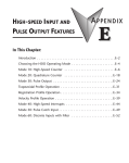
Mode 40 –
High Speed Interrupts
In This Chapter. . . .
Ċ Wiring the HS Interrupts
Ċ Configuring the HS Interrupt Parameters
Ċ Writing the Control Program
Ċ Verification of Proper Operation
Ċ Troubleshooting
16
6–2
Mode 40
High Speed Interrupts
High Speed Interrupts
Using the Interrupt Inputs, Mode 40
It is recommended that you read Chapter 1, Getting Started, which introduces the six
different modes of operation of the D2–CTRINT module, before selecting a mode.
Even though several features can be mixed from several modes, you must select
one of the modes as your primary mode. Mode 40 ––Interrupt Input Mode will be the
only mode covered in this chapter.
It is also important to read Chapter 2, concerning the general guidelines for field
wiring your device to the module. You may want to refer to Chapter 2 as you learn to
make use of the D2-CTRINT’s powerful pulse train outputs. A good place to begin is
to learn what each channel of the module represents when it is being used in the
pulse train mode.
Default Settings for Interrupt Input Mode 40
D2–CTRINT Terminals
CW
DL230
DL240/250–1/260
CCW
00
00
Interrupt
D2
01
Dis. Input
02
03
Mode 10
UP Counters
04
Dis. Input
Dis. Input
Not Used
Interrupt
01
02
03
04
Interrupt
Interrupt
Interrupt
Not Used
Installation and
Safety Guidelines
Note: Refer to pages 2–4 and 2–5 when wiring your
particular device.
Shown in the above diagram and illustration are points 00 through 03 which default
to high speed interrupt inputs when the module is used with the DL240/250–1/260
and set to operate in Mode 40. When the module is used with the DL230 only point 00
can be used for the interrupt, and the remaining channels can be used as discrete
filtered inputs. Chapter 8 contains information about the filter time constant.
When used with the DL240/250–1/260, the channels which are not configured as
interrupt inputs can be configured as “pulse catch” inputs, or as discrete filtered
inputs. More about pulse catching in Chapter 7.
Note: All interrupts have a pulse width of 0.1 ms and a pulse period of 0.5ms.
DL205 High Speed Counter
Interface Manual, 2nd Ed, Rev. A
6–3
High Speed Interrupts
The high speed interrupts of the D2–CTRINT interface module are intended for
applications that have one or more high–priority events which require special
operations to be acted upon immediately. When an interrupt occurs, the module tells
the CPU to go to a subroutine. The CPU finishes executing the instruction at that
point in the program scan, immediately suspends the program scan and jumps to a
subroutine which is identified by the interrupt input. Once the subroutine has been
executed, the normal program scan will continue at the point where the interrupt
occurred. (See diagram below.)
C
P
U
I
N
T
Mode 40
High Speed Interrupt
High Speed
Interrupts
Field Device
Main Program
Scan Cycle
Main Program
Interrupt
Subroutine
Subroutine execution
Interrupt
Installation and
Safety Guidelines
DL205 High Speed Counter
Interface Manual, 2nd Ed, Rev. A
Mode10
UP Counters
Subroutines can include math instructions, data instructions, or any necessary
routine which may be needed. One popular practice is to include immediate I/O
instructions in the subroutine. These instructions immediately update the I/O points
individually instead of waiting for a normal I/O update.
The order in which each input is to be acted upon is prioritized and determined by
which input point the user chooses to use as the interrupt. The inputs are given
labels X0 through X3 for the DL240/250–1/260, and X0 for the DL230. The highest
priority is input X0, with the next highest being X1, then X2, then the lowest priority
X3.
Each interrupt input signal is latched when it occurs. This means that as the module
senses a DC signal appearing at the input point for at least 0.4 milliseconds, it is held
ON until acted upon by the CPU even if the input changes.
6–4
Mode 40
High Speed Interrupts
High Speed Interrupts
High Speed Interrupts Process
Single Input Signal When the interrupt input point is turned on for a period of 0.1 milliseconds or longer,
the module will latch the signal and send the interrupt request to the CPU. Once the
Processing
CPU receives the request, the CPU stops the normal scan to execute the interrupt
routine and send a reset signal to the D2–CTRINT module.
ÉÉÉÉ
ÉÉ
ÉÉÉÉ
ÉÉ
ÉÉÉÉÉÉÉ
ÉÉÉÉÉÉÉ
0.2ms
Input signal (X0)
<0.1ms
This signal is ignored,
since it is less than 0.1 ms.
0.4ms
Latch output
CPU resets latch
Interrupt process and execute
interrupt subroutine 0.
Mode 10
UP Counters
Internal CPU
processing
Multiple Signals
from Same Input
There may be occasions where several signals are received close together, in a
short period of time, from the same input. In the diagram below, the time line reads
from left to right. The first signal is latched and takes 0.4 milliseconds to complete. If
another signal is received within that time span, the module will only recognize the
first signal and ignore the second one as shown below.
This signal is ignored.
Installation and
Safety Guidelines
0.4ms
ÉÉÉÉ
ÉÉÉÉÉÉÉ
ÉÉÉÉ
ÉÉÉÉÉÉÉ
ÉÉÉÉ ÉÉÉÉÉÉÉ
ÉÉÉÉÉÉÉ
ÉÉÉÉÉÉÉ
.2ms
Input signal (X0)
0.4ms
0.4ms
Latch output
CPU resets latch
Internal CPU
processing
DL205 High Speed Counter
Interface Manual, 2nd Ed, Rev. A
Interrupt process and execute
interrupt subroutine 0.
6–5
High Speed Interrupts
When the module senses signals simultaneously from several of the X0–X3 input
points, the priority system begins to work. The highest priority is given to X0, then X1,
X2 and X3. The diagram below shows two signals being received simultaneously.
ÉÉÉÉ
ÉÉÉÉ
ÉÉÉ
ÉÉÉ
ÉÉÉ
ÉÉÉÉÉÉÉ
ÉÉÉÉÉÉÉ
ÉÉÉÉÉÉÉÉ
ÉÉÉÉÉÉÉÉ
The example assumes that signals are true, and does not show the response delay.
Input signal (X0)
Input signal (X1)
Latch interrupt
request 0
Latch interrupt
request 1
Mode 40
High Speed Interrupt
Simultaneous
Signals from
Different Inputs
Reset latch 0
Reset latch 1
Interrupt
Main Program
Back to Main
Program
Execute
interrupt
subroutine 0
Leading Edge
Triggering
Execute
interrupt
subroutine 1
Mode10
UP Counters
Internal CPU
processing
The interrupt signals processed by the D2–CTRINT module are leading edge
triggered. The response time for the interrupt request acknowledgement is 0.1
milliseconds.
Installation and
Safety Guidelines
DL205 High Speed Counter
Interface Manual, 2nd Ed, Rev. A
6–6
Mode 40
High Speed Interrupts
High Speed Interrupts
Understanding V-Memory
Setup Locations
The High Speed Interrupt, Mode 40, associated with the D2-CTRINT requires
V-memory configuration in order to be used.
V-memory location V7633 is the most important of all the reserved memory areas
because it stores the value which lets the CPU know which mode has been selected.
The following diagram shows the 16-bit word and the various information it stores,
including the values used for the Counter Interface Module. The example shown
here is for High Speed Interrupt, Mode 40. The lower bits are set to 40 and the upper
bits are set to 10 so the backup battery is enabled. Together they form the
hexadecimal number 1040.
Bits
15
14
13
Memory Location V7633
12 11 10 9
8
7
6
5
0
0
0
1
0
Installation and
Safety Guidelines
Mode 10
UP Counters
1
0
0
0
0
1
0
0
4
4
3
2
1
0
0
0
0
0
0
0
Miscellaneous Setup
Binary Coded Decimal:
D2-CTRINT Mode Setup
Binary Coded Decimal:
00 = Not Used (default)
10 = Battery Enabled (DL230/240/250–1/260)
20 = Power Up in Run (DL230 only)
30 = Selects both Battery Enable
and Power Up in Run (DL230 only)
40 = Mode Change Enable in K–sequence (DL240 only)
50 = Battery Enable and Mode Change Enable
in K–sequence (DL240 only)
00 = Not Used
10 = UP Counting Mode
20 = UP/DOWN Counting Mode
30 = Pulse Output Train
40 = High Speed Interrupts
50 = Pulse Catching
60 = Discrete Filtered Inputs
NOTE: It is important to look at the entire 16 bits in V7633. If the RLL program only
sets the bits in the lower byte when entering the mode value, the upper bits will be
overwritten with zeros (0’s). Always enter a 4-digit BCD value in the V-memory. This
way, the proper value will be written into the upper bits.
There are also other V-memory locations which contain High Speed Counter
Interface setup information for each I/O point. The CPU will automatically configure
them with default values for the selected mode.
DL205 High Speed Counter
Interface Manual, 2nd Ed, Rev. A
6–7
High Speed Interrupts
When xx40 is written to V7633, the CPU places the following default values in
V-memory.
Configuration
Point 00/V7634 Point 01/V7635
Point 02/V7636
Point 03/V7637
Point 04
DL230
Hexadecimal
Value
Interrupt
0004
Discrete Input
1006
Discrete Input
1006
Discrete Input
1006
Not Used
Interrupt
0004
Interrupt
0004
Interrupt
0004
DL240/250–1/260 Interrupt
0004
Hexadecimal
Value
Explanation the
Values
Mode 40
High Speed Interrupt
Default Settings
Chapter 8 explains the discrete filtered inputs in detail. From the above table, 1006
for Point 01, DL230, is in the form xx06 where the 06 indicates the function (discrete
input) and the xx indicates the filter time in milliseconds (in this case 10 ms). The
value of 0004 is for high speed interrupts.
Default Settings for Interrupt Input Mode 40
CW
D2–CTRINT Terminals
CCW
DL230
D2
DL240/250–1/260
00
00
Interrupt
01
Dis. Input
03
04
Dis. Input
Dis. Input
Not Used
02
03
04
Interrupt
Interrupt
Interrupt
Not Used
Mode10
UP Counters
02
Interrupt
01
Note: Refer to pages 2–4 and 2–5 when
wiring your particular device.
Installation and
Safety Guidelines
DL205 High Speed Counter
Interface Manual, 2nd Ed, Rev. A
6–8
Mode 40
High Speed Interrupts
High Speed Interrupts
Custom Configuration
Up to this point, only Mode 40 default settings have been discussed. The default
settings will be suitable for many applications and will not require a custom
configuration. However, for those applications needing the defaults changed so the
D2–CTRINT will work for the applications, use the following table which contains the
options available.
Mode 40 Options
Point Number
V-Memory
Location
Possibility (One per
point)
point 00
V7634
High Speed Interrupt (external) 0004 (default)
Mode 10
UP Counters
point 01
V7635
point 02
V7636
Installation and
Safety Guidelines
point 03
point 04
V7637
---------
Hex Value
High Speed Interrupt (timed)
ttt4 (ttt=1 to 999ms timer setting)
Discrete Filtered Input
xx06 (xx=filter time)
Pulse Catch
0005
High Speed Interrupt
(DL240/250–1/260)
0004 (default for DL240/250–1/260)
Discrete Filtered Input
xx06 (xx=filter time) (default for DL230)
Pulse Catcher
(DL240/250–1/260)
0005 (DL240/250–1/260)
High Speed Interrupt
(DL240/250–1/260)
0004 (default for DL240/250–1/260)
Discrete Filtered Input
xx06 (xx=filter time) (default DL230)
Pulse Catcher
(DL240/250–1/260)
0005 (DL240/250–1/260)
High Speed Interrupt
(DL240/250–1/260)
0004 (default for DL240/250–1/260)
Discrete Filtered Input
xx06 (xx=filter time) (default DL230)
Pulse Catcher
(DL240/250–1/260)
0005 (DL240/250–1/260)
Not available in Mode 40
------------
When using Mode 40 with a high speed interrupt, it is better to select one or more of
the available I/O points. If only one of the points is being used as an interrupt with a
DL240/250–1/260 CPU, it may be more advantageous to select a different operating
mode (i.e. 10, 20, 30, 50, or 60). If this is done, configure one of the unused terminals
as an interrupt. For example, configure a CPU for an UP Counter Mode 10, and use
point 03 for a high speed interrupt. Read the individual chapters for an alternate
mode to choose; these chapters will be helpful in selecting a high speed interrupt as
a secondary feature.
DL205 High Speed Counter
Interface Manual, 2nd Ed, Rev. A
6–9
High Speed Interrupts
Configuring the
V–Memory
Step 1:
Enter the Mode
The DL240 or DL250–1/260 CPUs checks the V-memory to see if there is a
D2–CTRINT Module present. The number 40 will reside in V7633 if the module has
been configured properly. If the CPU finds that a Counter Interface Module is
present, other V-memory locations will be checked to see how each channel of the
module has been configured.
The values can be entered into memory by using either a handheld programmer or
by editing them into a control program using DirectSOFT32. The following
examples will show how to use DirectSOFT32 to configure the High Speed
Interrupts.
If Mode 40, Interrupt Input, has been chosen as the primary function, 40 must be
placed in V7633. The following DirectSOFT32 diagram shows the setup procedures
for communicating with the DL240/250–1/260 CPU. Refer to the DirectSOFT32
Programmers User Manual for more details.
Mode 40
High Speed Interrupt
Setting Up the CPU for the Interrupts
Mode10
UP Counters
Setting the
V-Memory
using RLL
Installation and
Safety Guidelines
Setting the
V-Memory
using the
Memory
Editor
Editing the D2–CTRINT setup at the beginning of the user program is the most
efficient method for setting up the counter mode. Should there be a need to change
any of the counter setup values after the PLC has been put in the RUN Mode, use the
Memory Editor to change the values. These values will only be temporary. They
should be put into the program if they are to be used permanently.
DL205 High Speed Counter
Interface Manual, 2nd Ed, Rev. A
6–10
High Speed Interrupts
Mode 40
High Speed Interrupts
The following RLL example shows how to set V–memory location V–7633 to Mode
40, Interrupt Input,. This is the location for all mode values for this module. Only one
mode (6 possible) can be entered, i.e. 10,20,30,40,50 or 60.
DirectSOFT32 Display
SP0
LD
K40
Load Mode 40 in Accumulator
OUT
V7633
Mode 10
UP Counters
Transfer Contents of
Accumulator to V7633
Step 2:
How Many
Interrupts
Two commands are needed to put the values into V-memory. The value must first be
loaded into the accumulator of the CPU, then the CPU must transfer the value to the
memory location. In this case, 40 is to be placed in V7633. This value is loaded into
the accumulator, LD K40. The CPU then writes this data to the memory location,
V7633, once it reads the OUT instruction, OUT V7633. Notice that an SP0 contact is
used in this rung. This relay is on for the first scan only. This will load the values into
memory initially, thereby keeping the scan time to a minimum.
Up to four (4) high speed interrupt inputs can be used with the DL240/250–1/260
CPUs and one (1) high speed interrupt for the DL230 CPU. The following steps will
discuss the programming for each channel which has an interrupt device wired to it.
Step 3:
Configure the
V-Memory
The table below gives a description for each of the V-memory locations that must be
configured for each I/O point which are selected to have high speed interrupt
capability.
Installation and
Safety Guidelines
V–Memory
Description
V7633
Primary Mode (Interrupt=40)
V7634
Point 00 and
Timer Value if Used as Timed Interrupt
V7635
Point 01
V7636
Point 02
V7637
Point 03
DL205 High Speed Counter
Interface Manual, 2nd Ed, Rev. A
6–11
High Speed Interrupts
There are two types of interrupts to choose: external interrupt and timed interrupt.
A four digit hex value is written to each of the memory locations shown in the table for
each I/O point which will receive interrupt signals. Every input point wired to receive
interrupts should have the value of 0004 for the lowest digit.
All four channels can be programmed to respond to external interrupt signals.
Channel 1 is the only one which can only be programmed as a timed interrupt. If the
timed interrupt is used, the time interval value is written in the first three digits of
V7634.
The interval time range is between 3 and 999 milliseconds.
For example the following means that Channel 1 is to be a 50 ms interrupt timer:
Bits
15
14
13
0
0
0
0
Memory Location V7634 Using Timed Interrupt
12 11 10 9
8
7
6
5
4
3
2
0
0
1
0
1
5
Interval Time in ms
0
0
0
0
0
0
1
1
0
Mode 40
High Speed Interrupt
Two Types of
Interrupts
0
0
4
Interrupt Value
Interrupt 0 will be executed every 50ms.
Mode10
UP Counters
Installation and
Safety Guidelines
DL205 High Speed Counter
Interface Manual, 2nd Ed, Rev. A
6–12
Mode 40
High Speed Interrupts
High Speed Interrupts
In the RLL example below, Channels 1 and 2 are configured to be high speed
interrupt points, and Channels 3 and 4 to be discrete filtered inputs. Channel 1 will be
a timed interrupt.
DirectSOFT32 Display
ENI
SP0
LD
K40
Set to Mode 40
OUT
V7633
LD
K3004
Timed Interrupt of 300 ms
at Point 00. Every 300ms
Interrupt 0 will be executed.
OUT
V7634
LD
K4
Regular Interrupt at Point 01
OUT
V7635
LD
K2006
Discrete Input w/20 ms filter
at Point 02
OUT
V7636
Mode 10
UP Counters
LD
K1006
Discrete Input w/10 ms filter;
at Point 03
OUT
V3637
END
Installation and
Safety Guidelines
INT
O0
Start of Interrupt Routine
X20
Y22
OUTI
X35
IRTC
X35
Y0
Y17
RSTI
IRT
DL205 High Speed Counter
Interface Manual, 2nd Ed, Rev. A
6–13
High Speed Interrupts
The following information may provide some assistance in handling any problems
which may be encountered when setting up the D2–CTRINT module, should they
occur. Experience has shown that most problems occur because of improper
configuration. Always re-check configuration before anything else.
For verifying types of inputs (or outputs) which do not relate to external High Speed
Interrupts, see the Chapters in this manual covering the specific function. Listed
below are some things that could possibly go wrong with the high speed interrupt
inputs:
1. An external field device wired to the interrupt channel seems to be working,
but there is no interrupt when the device is operated.
2. The status indicator LED is not lighting for the input point where the
interrupt is wired.
3. The CPU is executing the interrupt properly, but it does not continue its
normal scan after the interrupt subroutine has been completed.
4. The interrupt is not fast enough.
Interrupt Device
Working But No
Interrupt
Installation and
Safety Guidelines
DL205 High Speed Counter
Interface Manual, 2nd Ed, Rev. A
Mode10
UP Counters
Interrupt Occurs,
But No Normal
Scan Afterwards
Status Indicators -Is the LED for the channel in question lit when the field device
attached to it is closed? If it isn’t, then the logic side of the module is either not being
energized from that device or the LED is bad. A voltmeter can tell you if there is a
signal at the I/O point. If there is, and it does not light the corresponding LED on the
top of the module, then the LED must be bad.
Pulse Width – If the signal does not maintain a HIGH level for more than 0.1 ms,
then the CPU may never acknowledge that it is there. Use a field device which
produces a pulse longer than 0.1ms.
Wiring - Simple as this might seem, quite often poor wiring is the cause of many
problems. Make sure there is a complete electrical loop between the device and the
input module. Along with visual inspection, use a voltmeter to check the wiring.
Input Voltage - If the input device is sending a signal which is less than 12 volts,
most likely the counter will not function or it will function improperly. Replace the field
device with one which has a stronger output if necessary.
Improper Configuration - Make sure that the proper configuration has been setup
for the mode being used. Also make sure that the function block has been properly
labeled for the interrupt subroutine. The function block and the I/O point must have
the same octal number assigned.
When this happens there is usually an error in the subroutine itself. Look for endless
loops or conditional returns where the condition has not occurred. Make sure that a
return has been placed at the end of the subroutine. DirectSOFT32 will usually
indicate this type of error.
Mode 40
High Speed Interrupt
Troubleshooting