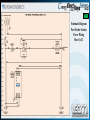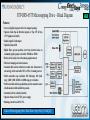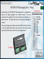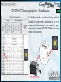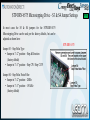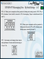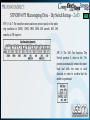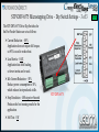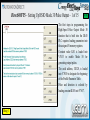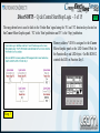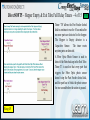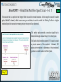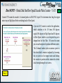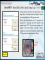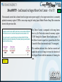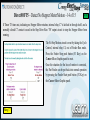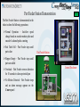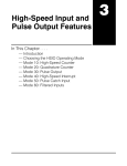
1
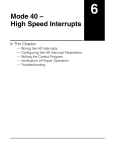
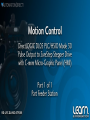
Motion Control Video Rundown and References This LEARN video covers the Part Feeder Station that uses the DirectLOGIC DL05 PLC’s built-in High-Speed Pulse Output, referred to as Mode 30, to control a SureStep Stepper System. A C-more Micro-Graphic panel is used as the operator interface. Various sensors are also used with the Part Feeder to control operational functions. The Part Feeder Station is the first stage of an overall application based on various Motion Control systems. The first and second stage are controlled with SureStep Stepper Systems using ADC products, with the final stage based on AutomationDirect’s SureServo Servo System. To the right is a list of topics covered in this video. 00:55 a. Application & Equipment b. Wiring (Schematic Diagram) c. Hardware Setup (Jumper & Dip Switches) d. DirectSOFT5 Ladder Logic & IBoxes e. C-more Micro-Graphic Panel (HMI) f. Operational Demonstration “Links” pointing to available technical information from AutomationDirect have been included, such as the example on the SureStep User Manual shown below. Link to SureStep Stepping Systems User Manual: http://bit.ly/r5dgUO Motion Control Video Rundown and References (cont’d) 02:30 This handout can be used to follow along with the video, and can also be useful as a refresher to the steps required to create a working Motion Control System using a DirectLOGIC DL05 PLC with DC outputs, programmed with the PLC’s built-in High Speed Pulse Output using Mode 30, controlling an AutomationDirect SureStep Stepper System, interfaced with a C-more Micro-Graphic panel, monitored with ADC sensors, and constructed using ADC wiring components. For additional information on AutomationDirect’s products that are a good choice for a Motion Control application, please refer to the Automation Notebook article titled ‘Starting with Steppers’ under the Tech Thread, Part 1 of 2 published in Issue 21 (Fall 2011), and Part 2 of 2 published in Issue 22 (Spring 2012). Various stepper motor control methods are discussed in this article. Links to Part 1 & 2 are shown below. The eight part video series titled ‘Motion Control – DirectLOGIC Micro PLC/CTRIO Module to SureStep Stepping System with C-more Micro-Graphic Panel (HMI)’ is another excellent resource detailing Motion Control System information. 8 Part Video Series: http://bit.ly/17OhoYU Link to “Starting with Steppers” Part 1: http:/bit.ly/J5U0tN Link to “Starting with Steppers” Part 2: http:/bit.ly/IQSjUb Application – Part Feeder Station The Part Feeder Station was designed to dispense one part at a time into a tube that carries the sequenced parts to the next station. The parts in this example application consists of six different colored marbles, steel balls, and brass balls. The parts are all approximately 14mm in diameter. The parts are stored in a cylindrical polycarbonate hopper. A slotted polycarbonate disk, coupled to an AutomationDirect NEMA 17 stepper motor, is used to rotate the disk. The slot in the disk allows one part at a time to drop into the slot as it rotates. The part then falls into the exit tube when it is positioned over the opening. The Part Feeder mechanism is built using T-slotted 80/20 framing. It includes a part hopper, slotted disk driven with a SureStep stepper motor, and a coupled Koyo encoder to provide speed control and jam detection. There is also a fiber optic photoelectric sensor to detect when the exit tube is full, and a capacitive proximity sensor to determine when the part hopper is empty. 03:27 Part Feeder Station Application – Control Panel Enclosure The Part Feeder Station controls are housed in a non-metallic JIC NEMA 4X enclosure with a window through the door. A C-more Micro-Graphic panel and the master control power circuitry push buttons are mounted through the enclosure’s window. Located on the enclosure’s panel are the DirectLOGIC DL05 PLC, AcuAMP DC current sensor, 24 VDC power supply used for the PLC’s DC inputs and also 24 VDC power to the AcuAMP, and the master control power circuitry relay. The SureStep stepper motor drive and stepper motor power supply are also mounted to the enclosure’s panel. AutomationDirect’s terminal blocks, wire duct, DIN rail, and machine tool wire are used to construct and wire the control panel enclosure. AutomationDirect multi-wire connector and multi-conductor flexible control cable is used to connect the control panel enclosure to the Part Feeder Station. 04:42 Control Enclosure Application - Schematic Diagrams The next two slides represent the schematic diagrams of the Part Feeder Station. The first schematic diagram shows the power circuitry which includes the Master Control circuitry with relay, ‘Power On’ push button and ‘Emergency Stop’ push button. The ADC Rhino 24 VDC power supply used to provide power to the PLC’s DC inputs, and power to the AcuAMP DC current sensor is also shown on the first schematic diagram. The second schematic diagram includes the DirectLOGIC DL05 PLC, SureStep stepper system motor, power supply and drive, Koyo incremental encoder, AcuAMP DC current sensor, 4-20 mA analog current input module, fiber optic photoelectric and capacitive proximity sensors, and C-more Micro-Graphic panel. The wiring for the Part Feeder controls uses different colored machine tool wires for the various conductors to help identify individual circuits, whereas wire numbering could have been just as easily used. Follow the codes for your application. Control Enclosure Panel 05:50 05:58 Schematic Diagram Part Feeder Station Power Wiring Sheet 1 of 2 06:19 Schematic Diagram Part Feeder Station DL05 PLC, Stepper System & HMI Sheet 2 of 2 F0-04AD-1 Analog Input Module Jumper Settings To detect if the Part Feeder is jammed, the current from the SureStep power supply to the SureStep drive is monitored using an AcuAMP DC Current Sensor. The 4-20mA signal from the DCT100-42-24-F AcuAMP Current Sensor is wired into channel 1 of the F0-04AD-1 Analog Current Input Module. The position of jumper J3 on the F0-04AD-1 4-Channel Analog Current Input Module determines the input signal level. The chooses are 4–20mA or 0–20mA. The module ships with the jumper not connecting the two pins, so that in this position, the expected input signal is 4–20mA. F0-04AD-1 F0-04AD-1 06:50 STP-DRV-6575 Microstepping Drive – Block Diagram Features: • Low cost, digital step motor driver in compact package • Operates from Step & Direction signals, or Step CW & Step CCW (jumper selectable) • Enable input & Fault output • Optically isolated I/O • Digital filters prevent position error from electrical noise on command signals; jumper selectable: 150 kHz or 2MHz • Rotary switch easily selects from many popular motors • Electronic damping and anti-resonance • Automatic idle current reduction to reduce heat when motor is not moving; switch selectable: 50% or 90% of running current • Switch selectable step resolution: 200 (full-step); 400 (halfstep); 2,000; 5,000; 12,800; or 20,000 steps per revolution • Switch selectable microstep emulation provides smoother, more reliable motion in full and half step modes • Automatic self test (switch selectable) • Operates from a 24 to 65 VDC power supply • Running current from 0.5 to 7.5A Link to Microstepping Drive Data Sheet: http://bit.ly/17mkQLQ 07:42 STP-DRV-6575 Microstepping Drive – Wiring External wiring to the STP-DRV-6575 Microstepping Drive is accomplished by using the two separate pluggable screw terminal connectors. The power connections for the supplied DC power and the stepper motor leads share a sixposition connector. The digital inputs and one output share an eight-position connector. Also seen in the diagram to the right are the Status LEDs, the Rotary Switch used to select the Stepper Motor based on part number or current rating, and the 8-position Dip Switch used to select the drive’s operating parameters. STP-DRV-6575 07:58 STP-DRV-6575 STP-DRV-6575 Microstepping Drive – Motor Selection 08:36 Use the Rotary Switch to select the motor being used based on either the stepper motor’s part number, or set by the stepper motor’s current rating. In this example the stepper motor used is part number STP-MTR-17060D, so the Rotary Switch is set to position 8. STP-MTR-17060D STP-DRV-6575 Microstepping Drive – S3 & S4 Jumper Settings In most cases the S3 & S4 jumpers for the STP-DRV-6575 Microstepping Drive can be used per the factory defaults, but can be adjusted as shown here: Jumper S3 – Step Pulse Type • Jumper in “1-2” position – Step & Direction (factory default) • Jumper in “1-3” position – Step CW / Step CCW Jumper S4 – Step Pulse Noise Filter • Jumper in “1-2” position – 2MHz • Jumper in “1-3” position – 150 kHz (factory default) STP-DRV-6575 09:04 STP-DRV-6575 Microstepping Drive – Dip Switch Settings – 1 of 3 09:46 SW 1 & 2: Reduce power consumption and heat generation by limiting motor running current to 100%, 90%, or 80% of maximum. Current should be increased to 120% if microstepping. (Torque is reduced/increased by the same %.) SW 4: Reduce power consumption and heat generation by limiting motor idle current to 90% or 50% of running current. (Holding torque is reduced by the same %.) SW 3: Anti-resonance and damping feature improve motor performance. Set motor and load inertia range to 0–4x or 5–10x. STP-DRV-6575 Microstepping Drive – Dip Switch Settings – 2 of 3 11:01 SW 5, 6 & 7: For smoother motion and more precise speed, set the pulse step resolution to 20000, 12800, 5000, 2000, 400 smooth, 400, 200 smooth, or 200 steps/rev. SW 8: The Self Test function, Dip Switch position 8, when in the ‘On’ position automatically rotates the motor back and forth two turns in each direction in order to confirm that the motor is operational. STP-DRV-6575 Microstepping Drive – Dip Switch Settings – 3 of 3 The STP-DRV-6575 Drive Dip Switches for the Part Feeder Station are set as follows: Current Reduction – 80% Application does not require full torque, so 80% is used to reduce heat. Load Inertia – 0-4X Application has little loading, so lower inertia can be used. Idle Current Reduction – 50% Reduce power consumption to 50%, which reduces heat produced at idle. Step Resolution – 400 steps/rev Smooth Produces the best running results for the application. Self Test - Off STP-DRV-6575 11:35 STP-DRV-6575 Microstepping Drive – Alarm Codes 11:55 In the event of a drive fault or alarm, the green LED will flash one or two times, followed by a series of red flashes. The pattern repeats until the alarm is cleared. DirectSOFT5 – Setting Up HSIO Mode 30 Pulse Output – 1 of 15 12:24 The first steps in programming the High-Speed Pulse Output Mode 30 function that is built into the DL05 PLC requires loading parameters into the assigned V-memory registers. Constant value K30 is loaded into V7633 to enable Mode 30 for generating output pulses. The octal address, O2320, is loaded into V7630 to designate the beginning of the Profile Parameter Table. Pulse and direction is selected by loading constant K103 into V7637. Rung 1 DirectSOFT5 – Setting Up HSIO Mode 30 Pulse Output (cont’d) – 2 of 15 13:45 Continuing the setup of the High-Speed Pulse Output Mode 30 function, additional parameters are loaded into the Profile Parameter Table: The constant K2000 is loaded into Vmemory address V2320 to select a Velocity Profile move. Constant K80000000 is loaded into double word size V-memory address V2321/2322 to select CCW direction. The stepper motor SPEED is set with an initial velocity of 100 pulses per second by loading constant K10 into V-memory address V2323. The loaded value is multiplied by a factor of 10. Rung 2 DirectSOFT5 – Cycle Control Start/Stop Logic – 3 of 15 14:48 The rung shown here is used to latch in the ‘Feeder Run’ signal using the ‘F1’ and ‘F2’ function keys located on the C-more Micro-Graphic panel. ‘F2’ is the ‘Start’ pushbutton and ‘F1’ is the ‘Stop’ pushbutton. Memory address V2010 is assigned in the C-more Micro-Graphic panel as the LED Control Word for the Function Key and LED object. Out Bit B2010.2 controls the LED on Function Key 3. Rung 3 DirectSOFT5 – Hopper Empty & Exit Tube Full Delay Timers – 4 of 15 15:36 Timer ‘T0’ allows the Part Feeder slotted disk to continue to run for 10 seconds after no more parts are detected in the hopper. The Hopper is Empty detector is a Capacitive Sensor. The timer resets anytime parts are detected. A Fiber Optic Photo Sensor is used to detect if the Parts back up in the Exit Tube. Timer T1 is used so that every part that triggers the Fiber Optic photo sensor doesn’t stop the Part Feeder slotted disk, and the part has to block the photo sensor for one second before the action is paused. Rung 4/5 DirectSOFT5 – Execute HSIO Mode 30 Parameters, Out Y0 – 5 of 15 16:47 The rung shown here controls the execution of the Velocity Profile that was setup with the HSIO Mode 30 parameters in rungs 1 and 2. Out Y0 produces the step pulses that are wired into the stepper drive. Rung 6 Contact C4 is the Feeder Run signal that is shown in rung 3. Timers T0 and T1 contacts enable the rung when the Hopper is not Empty and the Exit Tube is not Full respectively. Contact C7 is the contact from the circuit that detects if there is no motion from the stepper motor, indicating a jam or motor failure. DirectSOFT5 – Slotted Disk Fast/Slow Speed Circuit – 6 of 15 17:24 The encoder that is coupled to the Stepper Motor is used for several functions. In this rung the encoder’s marker pulse, labeled Z-channel, which occurs once per revolution, is used to switch the Velocity Profile to a higher rotational speed to increase how many parts per time period are dispensed. The marker pulse provides a one-shot signal that is latched in through internal relay C1 for Fast Speed. The latch is held-in while counter CT0 is used to count a pre-set amount of the encoder’s A-channel 100 pulses per revolution to determine at what rotational position to switch back to the Slow Speed. Rung 7 DirectSOFT5 – Slotted Disk Fast/Slow Speed Encoder Pulse Counter – 7 of 15 18:00 Counter CT0 counts the encoder’s A-channel pulses via DL05 PLC input X3 to determine how long the stepper motor stays in High Speed before switching back to Slow Speed. A pre-set of 85 counts is used in the application, which calculates to be .85 times 360 degrees equals 306 degrees in High Speed and 54 degrees in Slow Speed, which is over the point the part is dropped into the Exit Tube. Of course the count pre-set can be adjusted to produce different results. The Z-channel marker pulse occurrence point in the slotted disk’s rotation is adjusted by loosening the set screws on the stepper motor and holding the encoder in position while rotation the slotted disk, then tightening the set screws. Rung 8 DirectSOFT5 – Slotted Disk Fast/Slow Speed Change Logic – 8 of 15 19:02 The logic shown here determines the running velocity of the Stepper Motor. It switches between Slow Speed at 100 pulses per second and Fast Speed at 300 pulses per second. With the Fast Speed internal relay C1 de-energized, the constant K10 is loaded into the Profile Parameter Table memory register V2323. This value, times a multiplier of 10, produces a Slow Speed velocity of 100 pps. With C1 energized, the constant K30 is loaded into memory register V2323 to produce a Fast Speed velocity of 300 pps. Slotted Disk Rung 9/10 DirectSOFT5 – Analog Input IBox Instruction – 9 of 15 19:24 The current from the Stepper Motor Power Supply to the Stepper Motor Drive is monitored using an AcuAMP DC current sensor. The output signal from the AcuAMP is 4 to 20 mA and represents 0 to 50 Amps as setup on the sensor. The 4 to 20 mA signal is wired into a F0-04AD-1 analog input module located in the expansion slot of the DL05 PLC. To increase the current input resolution, ten turns are wrapped through the current sensor’s aperture, allowing 5 Amps to produce full scale output. The ANLGIN IBox instruction is used to configure the module with the Pointer Setup method as shown. Base equals K0, Slot # is K1, there are four input channels, thus K4 is used, Input Data Format in binary equals K1, and Data Address assigned to V2000. Rung 11 DirectSOFT5 – Jam Detected via Stepper Motor Over Current – 10 of 15 20:26 The measured current that is drawn from the stepper motor power supply by the stepper motor drive is constantly updated in memory register V2000 as was setup using the Analog Input Module Pointer Setup IBox instruction shown in the previous slide. Rung 12 The Driver Current is compared in the rung shown here to a Set Point value entered in memory register V2100 through the C-more Micro-Graphic panel. If the Driver Current is equal to or greater than the Over Current Set Point, then internal relay C5 is energized. This condition indicates that a Jam has occurred and signals the next set of rungs to reverse the direction of the Stepper Motor with the intensions of clearing the Jam. DirectSOFT5 – Jam Detected via Reverse Timer – 11 of 15 Rung 13 21:00 This rung looks for the C5 Jam signal as a result of the Stepper Motor Power Supply current that goes to the Stepper Motor Drive has exceeded the Set Point value. The signal is used as a one shot and latches in the circuit through internal relay C6, Jam Detected. Timer T2, programmed for 10 seconds, is used to set how long the Stepper Motor is ran in the reverse direction to clear the potential jam. When Timer T2 times out, the Reverse Rotation circuit is de-energized, and the Stepper Motor returns to running in its normal direction. DirectSOFT5 – Stepper Motor Forward/Reverse Logic – 12 of 15 21:25 The logic shown here determines the direction of the Stepper Motor. It switches between the normal Counter-Clockwise direction to a Clockwise direction. With the Reverse Rotation internal relay C6 energized, via a rising edge one shot, the constant K0 is loaded into the Profile Parameter Table memory register V2321/2322 to produce a CCW direction. With C6 de-energized, via a falling edge one shot, the constant K80000000 is loaded into memory register V2321/2322 to produce a CW direction. Rung 14/15 DirectSOFT5 – No Motion Detection via Encoder Pulses – 13 of 15 22:01 Timer T3 is used to detect if the Stepper Motor is jammed, or has stalled, by means of monitoring the B-channel pulses that are produced by the encoder when the Stepper Motor is rotating. The Timer is enable by the Step Drive Run signal ‘Y0’, and is programmed with a time of 0.2 seconds. The encoder pulses, input ‘X4’ are programmed into the Timer’s reset, and causes the Timer to be constantly reset as long as the Stepper Motor is rotating. Rung 16 DirectSOFT5 – Detect No Stepper Motor Motion – 14 of 15 22:49 If Timer T3 times out, indicating no Stepper Motor rotation, internal relay C7 is latched in through itself, and a normally closed C7 contact is used in the Step Drive Run ‘Y0’ output circuit to stop the Stepper Motor from running. The No Step Motion circuit is reset by taking the Cycle Control, internal relay C4, out of Feeder Run mode. Press the Feeder Stop push button (F1 Key) on the C-more Micro-Graphic panel to reset. Once the situation for the loss of motion is corrected, the Part Feeder can be put back into normal operation by pressing the Feeder Start push button (F2 Key) on the C-more Micro-Graphic panel. Rung 17 DirectSOFT5 – Documented Project – 15 of 15 23:27 The DirectSOFT5 ladder logic program as shown in this video is not overly complicated. The commented project is a good example of the various programming elements that are available to the end user. A majority of the programming basics that are a part of DirectSOFT5 are covered in the example project, including, a ‘control program’ that is used to configure the Mode 30 pulse output by loading parameters into predefined memory locations, timers to allow detection of parts and encoder pulses, a counter to accumulate rotary encoder pulses for motion detection, value compare logic instructions, outputs addressed by bit of word, logic latching internal relays, assigned contacts from the C-more Micro-Graphic panel, and an IBox instruction to configure the analog current input module. NOTE: A complete commented DirectSOFT5 project for the Motion Control demo presented here is available for downloading from the LEARN website. Look for the note below the video that mentions ‘take-away training PDF’s and Demo projects’. Link to DirectLOGIC PLCs Web site: http://bit.ly/Nyasby C-more Micro-Graphic Panel (HMI) 23:41 The C-more panel used in the example application consists of just one screen for simplicity. The HMI used in the example application is a 3” non-touch panel with green and red backlights, ADC part number EA1-S3ML-N. From the panel, the Part Feeder can be started and stopped using the F1 and F2 function keys. Indicators are used to show the Feeder in Run or Off mode. The stepper motor Fast/Slow speed is displayed. The stepper motor power supply Amperage from the AcuAMP current sensor is displayed, and the OverCurrent Set Point is displayed, and can be incremented up or down with the F4 and F5 function keys. Indicators are also included for the Exit Tube Full and Hopper Empty sensors. NOTE: A complete commented C-more MicroGraphic panel project for the Motion Control demo presented here is available for downloading from the LEARN website. Look for the note below the video that mentions ‘take-away training PDF’s and Demo projects’. Link to C-more Micro-Graphic Web site: http://bit.ly/Lvukxg Part Feeder Station Demonstration 24:40 The Part Feeder Station is demonstrated in the video to show the following operations: Normal Operation – fast/slow speed change based on encoder marker pulse and encoder A-channel pulse counting Exit Tube Full – Part Feeder stops until parts clear Part Feeder Station Hopper Empty – Part Feeder stops until parts are added Overload – Part Feeder reverses direction for 10 seconds to clear a potential jam No Motion Detected – Part Feeder stops and an alarm message appears on the C-more panel Control Enclosure Please note. Learn.AutomationDirect.com is an online streaming tutorial site offering training and information on a wide range of practical automation products. THE LEARN.AUTOMATIONDIRECT.COM WEBSITE, AND THE TRAINING AND INFORMATION PROVIDED IN CONNECTION THEREWITH, IS SUPPLIED "AS IS". These video presentations and other documents are provided by our associates to assist others in learning the products we sell and service. We make no representation, warranty or guaranty, whether expressed, implied or statutory, regarding the LEARN.AUTOMATIONDIRECT.COM website on the training, information and the content, including without limitation, the implied warranties of merchantability or fitness for a particular purpose, and any representation, warranty or guaranty that the foregoing will be accurate, complete, uninterrupted error free or non-infringing, is suitable for your particular application, nor do we assume any responsibility for the use of this information in your application. User suggestions, corrections and feedback are not only welcomed, but are essential to the maintenance of current content and the creation of new content. If there is a training idea, or correction to an existing presentation you would like us to consider, please complete and submit the suggestion form that is shown as a “Suggestions” link at the bottom of every page. Thank you! Copyright 2014, AutomationDirect.com Incorporated/All Rights Reserved Worldwide.