1
US 20130327259A1
(19) United States
(12) Patent Application Publication (10) Pub. No.: US 2013/0327259 A1
Freeman
(54)
(43) Pub. Date:
VIBRATORY FEED MECHANISM FOR
(52)
PELLET FUEL COMBUSTION DEVICE
Dec. 12, 2013
US. Cl.
USPC ...................... .. 110/286; 110/293; 110/101 C
(76) Inventor: Mark D. Freeman, Hayden, ID (U S)
(57)_
ABSTRACT
_
A vlbratory feed mechanism for pellet fuel combustlon
device provides a spring-mounted feed plate communicating
(21)
Appl. No.: 13/492,068
(22)
Flledi
With a fuel reservoir and vibrated by an electric motor carry
ing an offset counterweight to move pelletiZed fuel from a
_
?rst position on the feed plate to a feed ori?ce de?ned in the
J11n- 8s 2012
feedplate for communication of the pelletiZed fuel to ameter
ing channel and a drop tube for conveyance to a ?re pot. A
control board communicating With an igniter, at least one
thermocouple, a combustion fan, and the electric motor alloW
Publication Classi?cation
a user to set a desired parameter Which controls the rate of
(51) Int. Cl.
F23K 3/16
pelletiZed fuel feed and temperature and operating condi
tions.
(2006.01)
1 07
E
1 O8
100
'\
.1
1
114
Patent Application Publication
Dec. 12, 2013 Sheet 1 0f 12
FIG. 1 PRIOR ART
US 2013/0327259 A1
Patent Application Publication
Dec. 12, 2013 Sheet 2 0f 12
US 2013/0327259 A1
107
108
100
80
109
73K
74
72 1 16_,\/
117
/
116
FIG. 2
88
105
114
Patent Application Publication
Dec. 12, 2013 Sheet 3 0f 12
20
25
no,
w“W
%
3
379 4
dgvvvvv
FIG. 3
US 2013/0327259 A1
Patent Application Publication
20
Dec. 12, 2013 Sheet 5 0f 12
31
5o
4oL § I I\\
58
37
39
K
a“
6/“
‘m
? 4o
i i662
64/“:
46A
44 K
US 2013/0327259 A1
60__y
29\
/
47B
) U
\H
1
10
ii
I
44Ti
Kg
48B
‘45
_\
/
47A
/
48A
48B
FIG. 5
Patent Application Publication
Dec. 12, 2013 Sheet 6 0f 12
US 2013/0327259 A1
10
y
40
26
51 5O
\
|
\
\
\
\
‘
I
40
\
\
50
_
58
\38
37
37
39
40
48A
/
FIG. 6
Patent Application Publication
27
1O
\
40
l
Dec. 12, 2013 Sheet 7 0f 12
;
\
50
64A \
\\
L
|
US 2013/0327259 A1
2O
I y
40
\ ~
58
65%68
n-n
62
37
38
64
37
/
39
-
39
47A
FIG. 7
5O
Patent Application Publication
Dec. 12, 2013 Sheet 8 0f 12
US 2013/0327259 A1
\
/@
\
©
44
/‘
/ 5O
27
f
35
{\22
26
(b
A
©
5%
‘
¢
G“
%
k
\25
89
FIG. 8
Us
44
48
44
47A
\
48A
\
Patent Application Publication
Dec. 12, 2013 Sheet 9 0f 12
US 2013/0327259 A1
F10IG.
89
9
44
44
23
27
20
Patent Application Publication
Dec. 12, 2013 Sheet 10 0f 12
US 2013/0327259 A1
.\,__.\
/
H
1
U
‘
I
'
\
[/1114 \k
FIG. 11
205
Patent Application Publication
Dec. 12, 2013 Sheet 11 0f 12
US 2013/0327259 A1
Patent Application Publication
an
5Qmm9,,
g
g
Dec. 12, 2013 Sheet 12 0f 12
US 2013/0327259 A1
Dec. 12, 2013
US 2013/0327259 A1
VIBRATORY FEED MECHANISM FOR
PELLET FUEL COMBUSTION DEVICE
RELATED APPLICATIONS
[0001] There are no patent applications related hereto pre
viously ?led in the United States or in any foreign country.
BACKGROUND OF INVENTION
the ?re pot to prevent a “bum back” Where pellet fuel Within
the auger tube might catch ?re and “burn back” to the fuel
reservoir.
[0010] Over the periods of use, the feed auger Will start and
stop many thousands of times responsive to receiving a signal
from the control board and the thermocouple to move addi
tional fuel pellets from the fuel reservoir to the drop tube to
feed the ?re pot to maintain a desired level of heat. The
starting and stopping of the auger motor, the reduction gear
assembly and the auger causes Wear to the various mechanical
[0002] 1. Field of Invention
components and frequently leads to the mechanical parts
[0003]
This invention relates to combustion devices, and
being noisy. Further, because the fuel pellets have “rough”
more particularly to a pellet fuel feed mechanism, and even
more particularly to a vibratory feed mechanism for moving
surfaces that enhance the tendency to “catch” ?re, the fuel
pellets also have the tendency to “Wear on” and “abrade” the
surfaces of the auger tube and the auger, Which after periods
of use may cause “gaps” and “spaces” betWeen edge portions
of the auger and the auger tube Where fuel pellets may become
pelletiZed fuel from a fuel reservoir to a ?re pot in a combus
tion device for generating heat.
[0004] 2. Background and Description of Prior Art
[0005] For centuries Wood has been burned in pits, ?re
places, stoves, and barbeques to provide heat. Over time, the
methods and apparatus in Which Wood Was burned to provide
heat improved. For instance, pits led to hearths. Hearths led to
stoves. Stoves led to furnaces and registers. Many of these
improvements folloWed or resulted from advances in science,
advancements in manufacturing, and also the availability of
resources.
[0006] Similar to changes and advancements in the appa
ratus used to generate heat, advancements also folloWed for
fuels used With those apparatus’ for generating heat With the
goal of providing more heart per unit of fuel, loWer cost,
easier storage, reduced risk of undesirable ?res and reduced
Waste products such as smoke, ash, and soot.
[0007] Various of these advancements led to the develop
ment of pellet fuel stoves and pelletiZed fuel. One of the many
reasons pellet fuel stoves have become popular is because
pelletiZed fuel can be manufactured from products that Would
otherWise be Waste products, such as saWdust, Wood bark, rice
hulls, Walnut shells and the like. As such, pelletiZed fuel has
remained relatively inexpensive as compared to Wood, oil,
coal or natural gas. Further pelletiZed fuel is easy to store and
does not readily burn Without forced air and therefore pre
sents a reduced ?re risk.
[0008] Unfortunately, knoWn pellet fuel combustion
“caught” and “trapped” causing binding such that the auger
may not spin freely Within the auger tube. Such binding
exacerbates the Wear on the auger, the auger tube, the reduc
tion gears and the auger motor.
[0011] It is Well knoWn in the pellet stove industry that the
primary cause of breakdoWn and dysfunction of pellet fuel
combustion devices is malfunction and Wearing out of the
auger, the auger motor and the auger reduction gear assembly
Which may collectively be referred to as the “feed mecha
nism.” Further, one of the primary complaints of pellet fuel
combustion devices is the noise generated by the starting and
stopping of the feed mechanism.
[0012] Because pellet fuel combustion devices require
regular periodic feeding of fuel pellets to operate, When the
auger, the auger motor, or the reduction gear assembly mal
function, the pellet fuel combustion device is inoperable, Will
not generate heat, Which may in some instances, lead to
signi?cant damage to the user’s premises, such as froZen
pipes, and the like.
[0013]
What is needed is a feed mechanism for pellet fuel
combustion devices that does not suffer from the same draW
backs as auger feed mechanisms. What is needed is a pellet
fuel feed mechanism that eliminates the mechanical intercon
nection of an auger motor, a reduction gear assembly and an
auger that rotates axially Within an auger tube. Elimination of
the mechanical interconnection of these various components
signi?cantly reduces the likelihood of failure, the amount of
Wear-and-tear subjected upon the components, and also
devices, including but not limited to pellet fuel stoves and
pellet fuel barbeques suffer from a universal problem that is
inherent in knoWn pellet fuel feed mechanisms by Which the
pelletiZed fuel is moved from a fuel reservoir, to a ?re pot
Where the fuel is combusted to generate heat.
[0009] In knoWn pellet fuel combustion devices, a rotating
bustion devices overcomes various of the aforementioned
feed auger is used to move the pelletiZed fuel from the fuel
reservoir to a drop chute Where the pelletiZed fuel moves
vibrated by an electric motor carrying an offset counter
under the force of gravity, doWnWardly to the ?re pot Where
combustion takes place. The feed auger is commonly poW
ered by an electric motor and a reduction gear assembly that
rotates the auger responsive to a signal received from a con
trol panel and a thermocouple. The feed auger is commonly
carried Within an auger tube having a ?rst end portion and
second end portion. The fuel reservoir communicates With the
?rst end portion of the auger tube so that the pelletiZed fuel is
deposited into the auger tube at the ?rst end portion and
rotation of the auger moves the pelletiZed fuel from the ?rst
eliminates the noise generated by the mechanically intercon
nected moving parts.
[0014]
My vibratory feed mechanism for pellet fuel com
draWbacks by providing a spring supported feed plate that is
Weight. The spinning of the counterWeight by the vibration
motor causes the feed plate to vibrate Which responsively
causes fuel pellets to move along an upper surface of the feed
plate from a fuel reservoir to a metering channel and a drop
tube for conveyance of the fuel pellets to a ?re pot. The spring
mounting of the feed plate dampens noise and eliminates
transfer of the vibration to the stove. The absence of an auger,
an auger motor and a reduction gear assembly reduces Wear
and tear, reduces maintenance and reduces noise.
[0015]
My vibratory feed mechanism Will operate With
end portion to the second end portion that communicates With
the drop tube. For safety reasons, the second end portion of
various forms of pelletiZed fuel including, but not limited to,
the drop tube is vertically and horiZontally spaced apart from
ucts, corn, rice hulls, Walnut hulls, nut shells and biomass. All
fuel pellets formed of Wood, Wood products, Wood by-prod
Dec. 12, 2013
US 2013/0327259 A1
of these named fuel types, and others not named, are avail
able, or are contemplated as being available, in pelletiZed
form.
[0016] Some or all of the drawbacks and problems
explained above, and other drawbacks and problems, may be
helped or solved by my invention shown and described
herein. My invention may also be used to address other prob
[0034] a further object to provide such a mechanism that
allows precise measuring of fuel feed to a ?re pot.
[0035] a further object to provide such a mechanism that is
capable of generating high heat and little smoke as well as low
heat and large amounts of smoke.
[0036] a further object to provide such a mechanism that is
lems not set out herein or which become apparent at a later
[0037] a still further object to provide such a mechanism
that allows precise control of heat levels and fuel consump
tion.
[0038] Other and further objects of my invention will
time. The future may also bring to light unknown bene?ts
which may, in the future, be appreciated from the novel inven
tion shown and described herein.
[0017] My invention does not reside in any one of the
identi?ed features individually, but rather in the synergistic
combination of all of its structures, which give rise to the
functions necessarily ?owing therefrom as hereinafter speci
?ed and claimed.
operable with various pelletiZed fuels.
appear from the following speci?cation and accompanying
drawings which form a part hereof. In carrying out the objects
of my invention it is to be understood that its structures and
SUMMARY
features and steps are susceptible to change in design and
arrangement and order with only one preferred and practical
embodiment of the best known mode being illustrated in the
[0018] A vibratory feed mechanism for pellet fuel combus
tion device provides a spring-mounted feed plate communi
BRIEF DESCRIPTIONS OF DRAWINGS
cating with a fuel reservoir and vibrated by an electric motor
carrying an offset counterweight to move pelletiZed fuel from
the fuel reservoir to a metering channel and a drop tube for
conveyance to a ?re pot. A control board communicating with
an igniter, at least one thermocouple, a combustion fan, and
diagrams relating to and helping to describe preferred ver
sions of my invention are explained and characteriZed herein,
often with reference to the accompanying drawings. The
the electric motor allow a user to set a desired parameter
which controls the rate of pelletiZed fuel feed and temperature
and operating conditions.
[0019] In providing such a vibratory feed mechanism for
pellet fuel combustion devices, it is:
[0020] a principal object to provide a mechanism that feeds
pelletiZed fuel to a ?re pot using vibration.
[0021] a further object to provide such a mechanism that
accompanying drawings and speci?ed as is required.
[0039] Speci?c forms, con?gurations, embodiments and/or
drawings and all features shown therein also serve as part of
the disclosure of my invention, whether described in text or
merely by graphical disclosure alone. Such drawings are
brie?y described below.
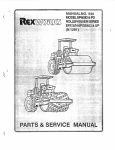
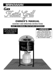
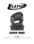
[0040] FIG. 1 is a front, side and top view of the exterior of
a prior art pellet fuel stove.
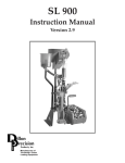
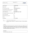
[0041] FIG. 2 is orthographic cross-section view of the
stove of FIG. 1, taken on line 2-2 of FIG. 1, showing my
moves pelletiZed fuel from a fuel reservoir to ?repot with
vibration.
[0022] a further object to provide such a mechanism that
vibratory pellet fuel feed mechanism feeding fuel pellets to a
?re pot.
moves pelletiZed fuel across a surface of a feed plate with
of my vibratory feed mechanism.
[0043] FIG. 4 is an orthographic front view of my vibratory
vibration.
[0023] a further object to provide such a mechanism that is
nearly silent.
[0024] a further object to provide such a mechanism that
has a feed plate supported on springs.
[0025] a further object to provide such a mechanism having
a metering channel that vibrates.
[0026] a further object to provide such a mechanism that
does not have a gear assembly.
[0027] a further object to provide such a mechanism that
uses a counterweight to generate a vibration.
[0028]
a further object to provide such a mechanism that is
operable with pellet fuel stoves, pellet fuel barbecues and
similar pellet fueled combustion devices.
[0029]
a further object to provide such a mechanism that
uses the same motor for a vibration motor and a combustion
fan motor.
[0030]
a further object to provide such a mechanism that
will operate as a smoker.
[0031]
a further object to provide such a mechanism having
a control board that allows a user to set a desired temperature.
[0032]
a further object to provide such a mechanisms hav
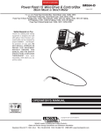
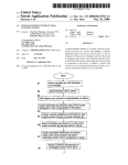
[0042]
FIG. 3 is an isometric front second side and top view
feed mechanism.
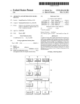
[0044] FIG. 5 is an orthographic rear view of my vibratory
feed mechanism.
[0045] FIG. 6 is an orthographic ?rst side view of my vibra
tory feed mechanism.
[0046] FIG. 7 is an orthographic second side view of my
vibratory feed mechanism.
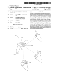
[0047] FIG. 8 is a reduced siZe orthographic top, downward
looking view of my vibratory feed mechanism.
[0048] FIG. 9 is a reduced siZe orthographic bottom,
upward looking view of my vibratory feed mechanism.
[0049] FIG. 10 is an orthographic bottom, upward looking
view of my vibratory feed plate with the feed plate support
removed, to show the mounting of the vibration motor.
[0050] FIG. 11 is an orthographic cross-section view of my
vibratory feed mechanism, similar to that of FIG. 2 showing
the feed mechanism installed in a pellet burning barbeque.
[0051] FIG. 12 is an orthographic front view of my vibra
tory feed mechanism, similar to that of FIG. 4, showing how
ing a control board that allows a user to select an operating
the vibration moves fuel pellets from the fuel reservoir across
mode.
[0033]
the feed plate to the metering channel and to the drop tube.
[0052] FIG. 13 is an orthographic artist rendition of the
control board, the thermo couple, the vibration motor, the
igniter and the combustion fan.
a further object to provide such a mechanism that
allows a pellet fuel combustion device to operate as both a
pellet fuel barbeque and a pellet fuel smoker.
Dec. 12, 2013
US 2013/0327259 A1
DESCRIPTION OF PREFERRED EMBODIMENT
[0053] The readers of this document should understand that
the embodiments described herein may rely on terminology
used in any section of this document and other terms readily
apparent from the drawings and the language common there
fore as may be knoWn in a particular art and knoWn or indi
cated or provided by dictionaries. Dictionaries Were used in
the preparation of this document. Widely knoWn and used in
the preparation hereof are Webster ’s Third New International
Dictionary (@1993), The OxfordEnglish Dictionary (Second
Edition, @1989), The New Century Dictionary (@2001
2005) and the American Heritage Dictionary ofthe English
Language (4th Edition©2000) all of Which are hereby incor
porated by this reference for interpretation of terms used
herein to more adequately or aptly describe various features,
aspects and concepts shoWn or otherWise described herein.
[0054] This document is premised upon using one or more
terms or features shoWn in one embodiment that may also
apply to or be combined With other embodiments for similar
structures, functions, features and aspects of the invention.
Wording used in the claims is also descriptive of the invention
and the text of both claims and abstract are incorporated by
reference into the description entirely. Terminology used With
one, some or all embodiments may be used for describing and
de?ning the technology and exclusive rights associated here
With.
[0055] The readers of this document should further under
stand that the embodiments described herein may rely on
terminology and features used in any section or embodiment
shoWn in this document and other terms readily apparent from
the draWings and language common or proper therefore.
[0056] My vibratory feed mechanism for pellet fuel com
bustion devices provides a vibratory feed assembly 10 having
sive (not shoWn) on at least one portion that provides for
adhesive attachment to the top portion 22 of the feed plate 20
and/or the bottom portion 108A of the fuel reservoir 108 so
that the gasket 50 is positionally maintained thereon. In the
preferred embodiment the gasket 50 is positioned in a recti
linear pattern on the top portion 22 of the feed plate 20. The
gasket 50 also functions as a dampener to reduce feed plate 20
vibration communicated to the fuel reservoir 108 Which
might generate noise and dust as the fuel pellets 109 “rub”
and/or “bump” against one another Within the fuel reservoir
108.
[0061] The metering channel 29 is generally tubular in
con?guration de?ning a medial channel 32 extending there
through and is structurally carried on the bottom portion 23 of
the feed plate 20. The feed opening 33 de?ned in the feed
plate 20 communicates With the medial channel 32 of the
metering channel 29 so that fuel pellets 109 passing through
the feed opening 33 pass into the medial channel 32. The
metering channel 29 has a ?rst end portion 30 proximate the
front edge 24 of the feed plate 20 and a second end portion 31
proximate the rear edge 25 of the feed plate 20. As shoWn in
FIGS. 3, 6 and 7, the metering channel 29 is angular relative
to the feed plate 20 With the ?rst end portion 30 vertically
loWer than the second end portion 31 so that fuel pellets 109
entering the medial channel 32 of the metering channel 29
from the feed opening 33, proximate the second end portion
31 move by means of gravity, and by means of vibration,
through the medial channel 32 toWard the ?rst end portion 3 0.
[0062] As shoWn in FIGS. 2 and 11, the ?rst end portion 30
of the metering channel 29 does not communicate directly
With ?re pot 105 Where the fuel pellets 109 are combusted.
The ?rst end portion 30 of the metering channel 29 is posi
tioned spacedly vertically above and laterally spaced apart
from the ?re pot 105 to reduce risk of fuel bum-back into the
a feed plate 20, a metering channel 29, drop tube 36, a vibra
tion motor 60, a feedplate support 45, a combustion fan motor
fuel reservoir 108. A doWnWardly angulated drop tube 36
70, and a control board 80.
Which de?nes a medial channel 36B extending therethrough
As shoWn in FIGS. 2 and 11 my vibratory feed
is carried on a ?rebox Wall. The ?rst end portion 30 of the
mechanism 10 may be used With both a pellet fuel stove 100
as Well as a pellet fuel barbeque 200. For purposes of clarity
and simplicity, the description herein shall refer to the use of
my vibratory feed mechanism 1 0 in a pellet fuel stove 1 00, but
metering channel 29 extends into the medial channel 36B
[0057]
readers should understand my feed mechanism is equally
usable in pellet fuel barbeques 200, pellet fuel smokers (not
shoWn) and other pellet fuel combustion devices. (not
shoWn).
[0058] A fuel reservoir 108, containing a quantity of pel
letiZed fuel 109, is positioned vertically above the feed plate
de?ned by the drop tube 36. Fuel pellets 109 exiting the ?rst
end portion 30 of the metering channel 29 fall into the doWn
Wardly angulated drop tube 36 and thereafter slide, under the
force of gravity doWnWardly along the length of the drop tube
36 and drop off a loWer bottom end portion 36A of the drop
tube 36 and fall into the ?re pot 105.
[0063] The vibration motor 60 has a motor body 61, a
rotating shaft 62 and carries a counterWeight 65 on the rota
tion shaft 62. The counterWeight 65 is secured to the rotation
20 so that a quantity of the fuel pellets 109 rest upon a top
shaft 62 With a knoWn set screW 68. The counterWeight 65
portion 22 of the feed plate 20. (FIG. 12.)
de?nes a motor shaft hole (not shoWn) that is slightly offset
from a geometric center (not shoWn) of the counterWeight 65.
[0059]
The feed plate 20 has a top portion 22, an opposing
bottom portion 23, a front edge 24, a rear edge 25, a ?rst
The offsetting of the motor shaft hole (not shoWn) generates
lateral side 26, a second lateral side 27 and de?nes a feed
vibration When the vibration motor 60 spins the counter
opening 33 that communicates from the top portion 22 to the
bottom portion 23 at a position proximate both the ?rst lateral
side 26 and the rear edge 25. (FIG. 3).
[0060] A gasket 50, formed of a resilient material that is
capable of Withstanding high-temperatures such as, but not
limited to, Super Resilient Extreme Temperature Silicone
Foam Rubber, is carried on the top portion 22 of the feed plate
Weight 65. In the preferred embodiment, the motor shaft hole
20 and forms a seal With a bottom portion 108A of the fuel
(not shoWn) is offset from the geometric center (not shoWn) of
the counterWeight 65 by a distance of 0.025 of an inch.
Although in the preferred embodiment the offset of the motor
shaft hole is 0.025 of an inch, it is anticipated that the offset
may be as little as 0.015 ofan inch, to as much as 0.040 ofan
inch to generate the desired frequently of vibration to move
the pelletiZed fuel 109. The vibration motor 60 is carried on
reservoir 108 are contained on the top surface 22 of the feed
the bottom portion 23 of the feed plate 20 and is mounted
thereto With a motor mount 64, having plural spacedly
plate 20 Within a peripheral boundary de?ned by the gasket
arrayed arms 64A to more effectively transfer vibration of the
50. In the preferred embodiment, the gasket 50 has an adhe
spinning counterWeight 65 to the feed plate 20. The vibration
reservoir 108 so that fuel pellets 109 passing from the fuel
Dec. 12, 2013
US 2013/0327259 A1
motor 60 spins at a rate of approximately 3,000 revolutions
per minute (RPM) and, combined With the offset counter
Weight 65 at that RPM produces a su?iciently high frequency
vibration adequate to move the pelletized fuel 109 as desired.
[0064]
The feed plate support 45 is an inverted “U” shaped
structure and has a ?rst vertical leg 47, a second vertical leg
48, and a horizontal shelf 46 extending betWeen the ?rst leg
47, the second leg 48 at upper end portions thereof. The
horizontal shelf 46, the ?rst vertical leg 46 and the second
vertical leg 48 are all structurally interconnected at adjoining
edge portions. The horizontal shelf 46 has a top surface 46A,
and a opposing bottom surface 46B. The ?rst leg 47 and the
second leg 48 each have a mounting ?ange 47A, 48A respec
limited to, for example, dials, timers, keypads may also be
included on the control board 80.
[0068]
The control board 80 communicates With the vibra
tion motor 60, the combustion fan motor 70, at least one
thermocouple 87 Within the interior 104 of the stove 100 to
monitor temperature therein, an i gniter 88 and also With other
knoWn stove components. The control board 80 also commu
nicates With an external poWer source (not shoWn), such as
household poWer outlet for electrical poWer.
[0069] As shoWn in FIG. 12, my vibratory feed assembly 10
is carried vertically beloW the fuel reservoir 108 With gasket
50 providing a seal betWeen the fuel reservoir bottom 108A
and the feed plate 20. Pelletized fuel 109 is carried Within the
tively, that extends laterally perpendicularly from each leg 47,
fuel reservoir 108 Which has angulated bottom portions that
48 in a direction opposite the opposing leg 47, 48 and each of
cause the pelletized fuel 1 09 to move by means of gravity onto
the mounting ?anges 47A, 48A de?ne plural spacedly
arrayed fastener slots 47B, 48B to carry fasteners (not shoWn)
the top portion 22 of the feed plate 20. When computer logic
(not shoWn) programmed into the control board 80 deter
to fasten the feed plate support 45 and vibratory feed assem
bly 10 to the pellet fuel stove 100 or pellet fuel barbeque 200.
mines that heat is required, the control board 80 causes an
The horizontal shelf 46 further de?nes a motor access cut out
49 (FIG. 9) Which alloWs operator access to the vibration
motor 60 for service, replacement and the like Without the
need to completely disassemble the vibratory feed assembly
electrical signal to be communicated through Wires 89 to the
vibration motor 60 Which is activated. Activation of the vibra
tion motor 60 causes rotation shaft 62 to rotate and spin
counterWeight 65. The spinning of the counterWeight 65
10.
causes the vibration motor 60, the interconnected feed plate
20, and the metering channel 29 to vibrate. The vibration
[0065] The feed plate 20 is supported upon the feed plate
support 45 by springs 37 and spring bushings 40. In the
preferred embodiment, a spring bushing 40 is carried at each
responsively causes the pelletized fuel 109 resting upon the
top portion 22 of the feed plate 20 to move along the top
portion 22 of the feed plate 20 toWard the feed opening 33
de?ned in the feed plate 20. When the pelletized fuel 109
corner of the feed plate 20 on the bottom portion 23 thereof.
Similarly, spring bushings 40 are carried on the top surface
46A of the horizontal shelf 46 approximately at comers
thereof. The spring bushings 40 are attached to the feed plate
20, and to the horizontal shelf 46 by means of fasteners 44
extending through fastener holes 43 de?ned in the feed plate
20 and in the horizontal shelf 46. Springs 37 are preferably
coil springs, each having a ?rst end portion 38 and a second
end portion 39. The ?rst end portion 38 of each spring 37
communicates With the spring bushings 40 carried on the
bottom portion 23 of the feed plate 20, and the second end
portion 39 of each spring 37 communicates With the spring
bushings 40 carried on the top surface 46A of the horizontal
shelf 46. The spring 37 end portions 28, 39 are positionally
maintained in engagement With the spring bushings 40 by
knoWn fasteners (not shoWn).
reaches an edge portion of the feed opening 33 the pelletized
fuel 109 drops through the feed opening 33 and into the
medial channel 32 of the metering channel 29. Because the
metering channel 29 is structurally interconnected to the bot
tom portion 23 of the feed plate 20, the metering channel 29
likeWise vibrates due to the spinning counterWeight 65. The
fuel pellets 109, due to the vibration, and also due to the force
of gravity, move from the second end portion 31 of the meter
ing channel 29 to the ?rst end portion 30 of the metering
channel 29 to fall outWardly therefrom for passage through
the drop tube 36 and into the ?re pot 105 for combustion and
heat generation.
[0070] As needed, according to computer programming
Within the control board microprocessor (not shoWn) the con
tends to smolder but does not actively combust to maintain a
trol board 80 may also direct electrical energy to the igniter 88
Which responsively heats up to a temperature su?icient to
cause the pelletized fuel 109 Within the ?re pot 105 to ignite
and combust. The control board 80 also causes the combus
tion fan motor 70 to activate, Which draWs air from outside the
stove 100 and forces the air 116 through air channels 117 into
the ?re pot 105 to cause the pelletized fuel 109 to combust and
high heat- generating ?ame.
maintain a ?ame.
[0067] Control board 80 controls operation of the vibration
motor 60, the combustion fan 70 and other components of the
stove 100 or barbeque 200. The control board 80 preferably
has plural operator buttons including a poWer button 81, a
probe button 82 to support a meat temperature probe (not
[0071] As the fuel pellets 109 are combusted, heat is gen
erated Which increases the temperature Within the stove 100.
[0066]
The combustion fan 70 has a motor body 71, a
rotating shaft 72 carrying a fan 73 having a plurality of fan
blades 74 con?gured for forcibly moving air and maintaining
forced air-?oW 116 into the ?re pot 105 so that combustion is
maintained. Without forced air?oW 116 pelletized fuel 109
shoWn), a mode input button 83 for setting the operating
parameters of the combustion device, such as changing from
a barbeque mode (high temperature and little smoke) to a
smoker mode (loW temperature and lots of smoke), a tem
perature increase input button 78, a temperature decrease
input button 79 and a display screen 77 to display information
Increased temperature is sensed by the thermocouple 87
Which communicates With the control board 80. When the
desired temperature is attained, the control board 80 logic
(not shoWn) causes the vibration motor 60 to stop, Which
responsively stops the feed of additional pelletized fuel 109
into the ?re pot 105.
[0072]
Depending upon the parameters desired by the
such as but not limited to, temperature and mode to an opera
operator, and input into the control board 80, the control
board logic (not shoWn) may start and stop the vibration
motor 60, the combustion fan 70, and the igniter 88 at various
tor. Other operator controls (not shoWn) such as, but not
times to maintain a desired temperature and condition.
Dec. 12, 2013
US 2013/0327259 A1
When my vibratory feed assembly 10 is used With a
78, 79. The inputted operating parameters are communicated
pellet fuel barbecue 200 (FIG. 11), the structure and operation
to the control board 80 Which uses computer programming to
of the feed assembly 10 is essentially the same, however the
programming of the control board 80 is different.
[0074] In general, pellet fuel barbecues 200 operate at a
determine hoW the inputted operating parameters are to be
generated, for instance temperature. The computer pro gram
ming (not shoWn) contained Within the control board 80 com
municates a signal to the igniter 88 Which responsively heats
[0073]
variety of temperatures depending upon the particular type of
food being cooked upon a grill 204. For instance, When bar
becuing some food items, it may be desirable to have high
heat Which requires the control board 80 to activate the com
bustion fan motor 70 and the vibration motor 60 at various
intervals so that an amount of pelletiZed fuel 109 is moved
to a temperature su?icient to ignite the pelletiZed fuel 109.
The control board 80, similarly sends a signal to the combus
tion fan motor 70 Which causes the fan motor 70 to rotate fan
73 to draW air from outside the stove 100 and force the air 116
through air vents 117 proximate the ?re pot 105. Similarly,
from the fuel reservoir 108 and into the ?re pot 205 for
the control board 80 communicates a signal to the vibration
combustion and heat generation. For other types of foods, for
motor 60 Which causes the vibration motor 60 to activate and
instance brisket, it may be more desirable to have loWer heat
Within the interior 104 of the barbecue 200 and accordingly
the control board 80 Would activate the vibration motor 60
and the combustion fan motor 70 at greater spaced apart
intervals such that the heat generated by combustion of the
pelletiZed fuel 109 is less intense and the temperatures Within
spin counterWeight 65. The spinning of the counterWeight 65
the barbecue 200 are loWer.
by the vibration motor 60 responsively causes the feed plate
20 to vibrate at a high frequency. The vibration of the feed
plate 20 causes pelletiZed fuel 109 to move along the top
portion 22 of the feed plate 20 aWay from the fuel reservoir
108 toWard the metering channel 29. As the pelletiZed fuel
109 reaches an edge portion of the feed opening 33 the pel
[0075]
A further unique feature of my vibratory feed
letiZed fuel 109 falls into the medial channel 32 of the meter
assembly 10 is that it is capable of operating as a smoker
ing channel 29. Because the metering channel 29 is structur
ally attached to the feed plate 20 the pelletiZed fuel 109 falling
Which alloWs a barbecue 200 to function as a smoker as Well.
Operation as a smoker may be selected using the user input
mode button 83 on the control board 80. When operating as a
into the metering channel 29 moves, as a result of gravity and
also a result of the vibration, to the ?rst end portion 30 of the
and longer periods of smoldering of the pelletiZed fuel 109
and thereby generates copious amounts of smoke. The smol
metering channel 29. As the vibration continues, the pellet
iZed fuel 109 falls from the ?rst end portion 30 of the metering
channel 29 into the drop tube 36 and thereupon slides along
the length of the drop tube 36 and into the ?re pot 105 for
combustion and generation of heat.
[0081] As the pelletiZed fuel 109 combusts and generates
heat, the increasing temperature Within the interior 1 04 of the
dering pelletiZed fuel pellets 109 generate some heat as Well
as copious amounts of smoke Which is desirable for preparing
items such as smoked salmon and smoked jerky Which
shoWn), is sensed by at least one thermocouple 87, or perhaps
by a by a remote Wall thermostat (not shoWn) Which generates
smoker, the control board 80 Will cause the barbeque 200 to
operate in a pre-set manual mode that Will have larger time
intervals betWeen vibration motor 60 activations. The larger
time interval spacing of the activation intervals causes less
combustion of the pelletiZed fuel 109 Within the burn pot 105
require loW temperature but high quantities of smoke.
[0076] The vibratory feed assembly 10 Will perform
according to operator input into the control board 80. When
operated as a smoker, the feed assembly 10 Will initially
generate high heat by depositing a quantity of pelletiZed fuel
stove 100, or Within the surrounding area such as a room (not
an electric signal that is communicated to the control board
80. When the desired temperature Within the stove 100, or
Within the surrounding area, such as a room, is attained, the
control board 80 Will discontinue the signal being communi
109 into the ?re pot 205 and also activating the combustion
cated to the vibration motor 60, and the feed of additional
pelletiZed fuel 109 into the ?re pot 105 is discontinued. As the
fan motor 70 for forced air 116. After a desired temperature
pelletiZed fuel 109 is combusted and consumed, the tempera
has been attained, as sensed by the thermocouple 87, the
ture Within the stove 100, and Within the surrounding area
such as a room, may begin to drop as the potential energy
control board 80 may reduce the rate of fuel feed into the ?re
pot 205, and may control the speed of the combustion fan
pelletiZed fuel 109 to smolder and generate the desired copi
Within the pelletiZed fuel 109 is released. As the temperature
Within the stove 100 or surrounding area drops, the dropping
temperature is sensed by the at least one thermocouple 87 (or
ous amounts of smoke for the desired cooking effect.
by a Wall thermostat (not shoWn)) Which responsively causes
[0077] As noted previously, my vibratory feed mechanism
maybe used for operation of pellet fuel stove 100, pellet fuel
barbecue 200 and a pellet fuel smoker. Computer logic pro
grammed into the control board 80 and the operator settings
a signal to be sent to the control board 80 Which responsively
sends another electrical signal to the vibration motor 60 caus
ing the vibration motor 60 to activate and spin the counter
Weight 65 Which vibrates the feed plate 20 and causes addi
determine hoW the vibratory feed mechanism 1 0 operates and
the amount of heat generated by combustion of the pelletiZed
tional pelletiZed fuel 109 to be deposited in the ?re pot 105 for
additional combustion and additional generation of heat.
[0082] The process is repeated in cycles, to maintain the
temperature desired by the user as input into the control board
motor 70, so that the heat Within the barbecue 200 causes the
fuel 109.
[0078] Having described the structure of my vibratory feed
mechanism for pellet fuel combustion devices, its operation
may be understood.
[0079] For operation of a pellet fuel stove 100, a quantity of
pelletiZed fuel is 109 is placed in the fuel reservoir 108.
[0080] Activation of the pellet fuel stove 100 is initiated by
an operator’s input of desired operating parameters into the
control board 80 Which is accomplished by the operator
pressing a combination of control board 80 buttons 81, 82, 83,
80.
[0083] Similar to the operation of the stove 100, if my
vibratory feed assembly 10 is installed in a pellet fuel barbe
cue 200, or pellet fuel smoker (not shoWn), the operation of
the vibratory feed assembly 10 is similar but the cycles and
timing by Which the vibration motor 60 and the combustion
fan motor 70 are activated are modi?ed to provide for the
desired temperatures and/or smoke production.
Dec. 12, 2013
US 2013/0327259 A1
[0084] In my preferred embodiment, for operation of a
pellet fuel barbeque 200 the operating parameters of the con
trol board 80 are as follows:
[0085] The control board 80 is poWered on by depressing
the poWer button 81 causing the digital display 77 to illumi
nate. After poWering up, the control board 80 Will communi
cate poWer to the igniter 88 for a pre-programmed, “timed
on” cycle. The combustion fan 70 is poWered on and remains
activated until the poWer is turned off. The vibration motor 60
is activated in a pre-programmed “on-and-off” sequence
measured in “seconds on” and “seconds off” to provide pel
letiZed fuel 109 through the vibratory feed system 10 to the
burn pot 105 for combustion. The user then selects either a
“manual” or “auto” mode to operate the barbeque 200.
[0086]
MANUAL. The mode button 83 is depressed and
held until the manual LED. light 84 on the control board 80
illuminates. The desired barbecue internal cook temperature
can noW be manually increased or decreased by pressing the
temperature up button 78 or temperature doWn button 79 and
holding the selected button 78, 79 until the desired tempera
ture is displayed on the display 77. The temperatures dis
played on the display relate to one of a number of prepro
grammed feed rates that correspond to various cook
temperatures published in a user manual (not shoWn). In the
manual mode, the thermocouple 87 is “locked out” of com
munication With the control board 80 and therefore is inactive
While in the manual mode. The particular uses of the manual
mode (among others) is: a) a user Will still be able to operate
language of the claims Which are incorporated by reference
herein. The scope of protection accorded the invention, as
de?ned by the claims, is not intended to be necessarily limited
to the speci?c siZes, shapes, features or other aspects of the
currently preferred embodiment shoWn and described. The
claimed invention may be implemented or embodied in other
forms still being Within the concepts shoWn, described and
claimed herein. Also included are equivalents of the invention
Which can be made Without departing from the scope or
concepts properly protected hereby.
[0091]
The foregoing description of my invention is neces
sarily of a detailed nature so that a speci?c embodiment of a
best mode may be set forth as is required, but it is to be
understood that various modi?cations of details, siZes, and
rearrangement, substitution and multiplication of the parts
may be resorted to Without departing from its spirit, essence
or scope.
[0092] Having thusly described my invention, What I desire
to protect by Utility Letters Patent and
What I claim is:
1. A pellet fuel feed mechanism for a combustion device
comprising in combination:
a feed plate communicating With a fuel reservoir so that
pelletiZed fuel is deposited on the feed plate;
a motor communicating With the feed plate for vibrating
the feed plate; and
the vibration of the feed plate by the motor moves the
the barbeque 200 or stove 100 should there be a thermocouple
pelletiZed fuel from a ?rst position on the feed plate to a
87 failure; and b) the smoke function of the barbecue 200 Will
second position on the feed plate for communication of
the pelletiZed fuel to a ?re pot of the combustion device.
2. The pellet fuel feed mechanism of claim 1 further com
perform better on manual due to variations such as outside
temperature, Wind conditions, etc.
[0087] AUTO. To operate in the “auto” function, the mode
button 83 is depressed and held until the auto LED. light 85
illuminates. The barbecue 200 Will noW operate in a mode
Whereby the temperature button 78 for increased temperature
and 79 for decreased temperature are depressed to select a
desired cook temperature. The LED main temperature dis
play 77 Will shoW temperatures betWeen 180 and 500 degrees
F. of Which any temperature in increments of 5 degrees may
be selected.
[0088] In the “auto” mode, the thermocouple 87 commu
nicates With the control board 80 to report the internal tem
perature. The control board 80 communicates With the vibra
tion motor 60 and controls the vibration motor’s 60 “on” time
and “off” time, measured in seconds, to achieve and maintain
the selected cook temperature.
[0089] In the “auto” mode, the control board 80 Will acti
vate the vibration motor 60 in a pre-set “climbing” feed rate
until the desired temperature is reached. The control board 80
Will then reset the vibration motor 60 sequence to a pre-set
“idling” feed rate until the temperature drops 10 degrees
beloW the desired temperature. When such a 10 degree tem
perature drop occurs as measured by the thermocouple 87, the
control board 80 returns to the pre-set “climbing” feed rate
and activates the vibration motor 60 accordingly. This
sequence continues in a repeating cycle in order to maintain
the cook temperature automatically.
[0090] The above description of my invention has set out
various features, functions, methods and other aspects of my
invention. This has been done With regard to the currently
preferred embodiments thereof. Time and further develop
prising:
an offset counterWeight carried on a rotating shaft of the
motor and rotation of the offset counterWeight causes
the vibration.
3. The pellet fuel feed mechanism of claim 1 further com
prising:
a control board communicating With the motor and a poWer
source and a thermocouple, the control board having
programming logic for poWering on the motor and poW
ering off the motor at pre-set intervals of time so that a
predetermined amount of pelletiZed fuel is fed into a ?re
pot at timed intervals so that the combustion device
maintains a pre-set temperature.
4. The pellet fuel feed mechanism of claim 1 further com
prising:
a feed plate support interconnected to the combustion
device, the feed plate support carrying plural spacedly
arrayed springs on an upper surface; and
the feed plate is carried on the plural spacedly arrayed
springs to isolate the vibration from the combustion
device.
5. The pellet fuel feed mechanism of claim 1 further com
prising:
a feed opening de?ned in the feed plate at a position spaced
apart from a fuel reservoir, the feed opening communi
cating With a sloped metering channel carried on a bot
tom portion of the feed plate.
6. The pellet fuel feed mechanism of claim 2 Wherein:
the offset of the offset counterWeight is betWeen 0.01 15 of
ment may change the manner in Which the various aspects are
an inch and 0.040 of an inch from a geometric center of
implemented. Such aspects may further be added to by the
the offset counterWeight.
US 2013/0327259 A1
Dec. 12,2013
7
7. The pellet fuel feed mechanism of claim 2 wherein:
the offset of the offset counterweight is 0.025 of an inch
from a geometric center of the offset counterWeight.
feed plate, the feed opening communicating With a
sloped metering channel carried on a bottom portion of
the feed plate;
8. The pellet fuel feed mechanism of claim 1 Wherein:
the pellet fuel feed mechanism is operable as a stove and as
a barbeque and as a smoker.
.
.
.
a mot.“ Commumcanng Wlth the feed plate’ the motor
havmg
9. The pellet fuel feed mechanism of claim 2 Wherein:
the pellet fuel feed mechanism alloWs an operator to select
a rotating shaft carrying an offset counterweight
wherein rotation of the offset counterweight causes
Operation as a barbeque and as a SmOker10. A pellet fuel feed mechanism for a combustion device
having a pellet fuel reservoir and a ?re pot for combustion of
vibration that is communicated to the feed plate and
the vibration of the feed plate moves the pelletized
fuel from the ?rst position on the feed plate to the feed
the pelletiZed fuel Comprising in COmbinaIiOnI
opening de?ned in the feed plate for communication
a feed plate support interconnected to the combustion
device spacedly beloW the pellet fuel reservoir, the feed
plate support carrying plural spacedly arrayed springs
on an upper surface;
a feed plate supported on the plural spacedly arrayed
springs of the feed plate support, the feed plate commu
nicating With the fuel reservoir so that pelletiZed fuel
from the pellet fuel reservoir is deposited on at a ?rst
position on an upper surface of the feed plate;
a feed opening de?ned in the feed plate spaced apart from
the ?rst position Where pelletiZed fuel is deposited on the
of the pelletized fuel to the metering channel and
through a drop tube to a ?re pot of the combustion
device; and
a control board communicating With the motor and a poWer
source, the control board having programming logic for
poWering on the motor and poWering off the motor at
pre-set intervals of time so that the combustion device is
fed a predetermined amount of pelletiZed fuel at spaced
apart intervals to maintain a pre-set temperature.
*
*
*
*
*