1
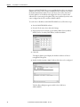
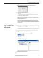
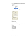
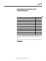
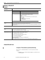
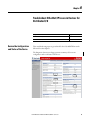
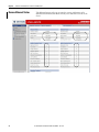
Application Technique Troubleshoot EtherNet/IP Networks Important User Information Read this document and the documents listed in the additional resources section about installation, configuration, and operation of this equipment before you install, configure, operate, or maintain this product. Users are required to familiarize themselves with installation and wiring instructions in addition to requirements of all applicable codes, laws, and standards. Activities including installation, adjustments, putting into service, use, assembly, disassembly, and maintenance are required to be carried out by suitably trained personnel in accordance with applicable code of practice. If this equipment is used in a manner not specified by the manufacturer, the protection provided by the equipment may be impaired. In no event will Rockwell Automation, Inc. be responsible or liable for indirect or consequential damages resulting from the use or application of this equipment. The examples and diagrams in this manual are included solely for illustrative purposes. Because of the many variables and requirements associated with any particular installation, Rockwell Automation, Inc. cannot assume responsibility or liability for actual use based on the examples and diagrams. No patent liability is assumed by Rockwell Automation, Inc. with respect to use of information, circuits, equipment, or software described in this manual. Reproduction of the contents of this manual, in whole or in part, without written permission of Rockwell Automation, Inc., is prohibited. Throughout this manual, when necessary, we use notes to make you aware of safety considerations. WARNING: Identifies information about practices or circumstances that can cause an explosion in a hazardous environment, which may lead to personal injury or death, property damage, or economic loss. ATTENTION: Identifies information about practices or circumstances that can lead to personal injury or death, property damage, or economic loss. Attentions help you identify a hazard, avoid a hazard, and recognize the consequence. IMPORTANT Identifies information that is critical for successful application and understanding of the product. Labels may also be on or inside the equipment to provide specific precautions. SHOCK HAZARD: Labels may be on or inside the equipment, for example, a drive or motor, to alert people that dangerous voltage may be present. BURN HAZARD: Labels may be on or inside the equipment, for example, a drive or motor, to alert people that surfaces may reach dangerous temperatures. ARC FLASH HAZARD: Labels may be on or inside the equipment, for example, a motor control center, to alert people to potential Arc Flash. Arc Flash will cause severe injury or death. Wear proper Personal Protective Equipment (PPE). Follow ALL Regulatory requirements for safe work practices and for Personal Protective Equipment (PPE). Allen-Bradley, Rockwell Software, and Rockwell Automation are trademarks of Rockwell Automation, Inc. Trademarks not belonging to Rockwell Automation are property of their respective companies. Summary of Changes This manual contains new and updated information. Changes throughout this revision are marked by change bars, as shown to the right of this paragraph. New and Updated Information This table contains the changes made to this revision. Topic Page Added Additional Resources tables. 5 Added flowchart for Assigning IP Addresses to EtherNe/IP Devices. 8 Added Reset to Factory Default section 14 Added Optimize an EtherNet/IP Network section 16 Added Access Web Browser Diagnostics 17 Updated Speed section 19 Updated Duplex section 19 Updated Autonegotiate section 20 Updated CPU section 21 Updated Interface Errors section 21 Updated CIP MSG Connections section 23 Updated CIP Connection Timeouts section 24 Updated TCP Connections section 24 Updated I/O Packets per Second section 25 Updated HMI Packets per Second section 25 Updated Missed Packets per Second section 26 Added Network Status (NET) 30 Added Links Status (LINK-)Single EtherNet/IP Port section 30 Added Links Status (LINK1 and LINK2)-Embedded Switch EtherNet/IP Ports section 31 Added Review the Configuration and Status of the Device section 33 Added Review Ethernet Status section 36 Updated General Solutions section 39 Updated Specific Issues section 40 Added Review the Configuration and Status of the Device section 43 Added Review Ethernet Status section 46 Added Troubleshoot EtherNet/IP Issues in PowerFlex Drives chapter 49 Rockwell Automation Publication ENET-AT003B-EN-P - June 2014 1 Summary of Changes Notes: 2 Rockwell Automation Publication ENET-AT003B-EN-P - June 2014 Table of Contents Preface Assign IP Addresses to EtherNet/IP Devices Troubleshooting Intermittent or Slow EtherNet/IP Networks EtherNet/IP Status Indicators Troubleshoot EtherNet/IP Issues in Controller Systems Troubleshoot Embedded Switch EtherNet/IP Networks Troubleshoot EtherNet/IP Issues in Devices for Distributed I/O Troubleshoot EtherNet/IP Issues in PowerFlex Drives Additional Resources . . . . . . . . . . . . . . . . . . . . . . . . . . . . . . . . . . . . . . . . . . . . . . . 5 Set an IP Address via Rotary Switches. . . . . . . . . . . . . . . . . . . . . . . . . . . . . . . . 8 Assign an IP Address with a BOOTP/DHCP Server . . . . . . . . . . . . . . . . . . 9 Assign an IP Address with RSLinx Software . . . . . . . . . . . . . . . . . . . . . . . . 11 Assign an IP Address within the Studio 5000 Environment . . . . . . . . . . 13 Reset to Factory Default . . . . . . . . . . . . . . . . . . . . . . . . . . . . . . . . . . . . . . . . . . 14 Optimize an EtherNet/IP Network . . . . . . . . . . . . . . . . . . . . . . . . . . . . . . . 16 Common Network Issues . . . . . . . . . . . . . . . . . . . . . . . . . . . . . . . . . . . . . . . . . 16 Assumption 1: The network was previously functioning . . . . . . . . . 16 Assumption 2: The EtherNet/IP device has a valid IP address . . . . 17 Access Web Browser Diagnostics . . . . . . . . . . . . . . . . . . . . . . . . . . . . . . . . . . 17 Speed . . . . . . . . . . . . . . . . . . . . . . . . . . . . . . . . . . . . . . . . . . . . . . . . . . . . . . . . . . . 19 Duplex . . . . . . . . . . . . . . . . . . . . . . . . . . . . . . . . . . . . . . . . . . . . . . . . . . . . . . . . . . 19 Duplex Mismatch Corrective Actions . . . . . . . . . . . . . . . . . . . . . . . . . . 20 Autonegotiate . . . . . . . . . . . . . . . . . . . . . . . . . . . . . . . . . . . . . . . . . . . . . . . . . . . 20 CPU . . . . . . . . . . . . . . . . . . . . . . . . . . . . . . . . . . . . . . . . . . . . . . . . . . . . . . . . . . . . 21 Interface Errors . . . . . . . . . . . . . . . . . . . . . . . . . . . . . . . . . . . . . . . . . . . . . . . . . . 21 CIP Connections . . . . . . . . . . . . . . . . . . . . . . . . . . . . . . . . . . . . . . . . . . . . . . . . 23 CIP Connection Timeouts. . . . . . . . . . . . . . . . . . . . . . . . . . . . . . . . . . . . 24 TCP Connections . . . . . . . . . . . . . . . . . . . . . . . . . . . . . . . . . . . . . . . . . . . . . . . 24 I/O Packets per Second . . . . . . . . . . . . . . . . . . . . . . . . . . . . . . . . . . . . . . . . . . . 25 HMI Packets per Second . . . . . . . . . . . . . . . . . . . . . . . . . . . . . . . . . . . . . . . . . 25 Missed Packets per Second . . . . . . . . . . . . . . . . . . . . . . . . . . . . . . . . . . . . . . . . 26 Network Status (NET) . . . . . . . . . . . . . . . . . . . . . . . . . . . . . . . . . . . . . . . . . . . 30 Links Status (LINK) - Single EtherNet/IP Port. . . . . . . . . . . . . . . . . . . . . 30 Links Status (LINK1 and LINK2) - Embedded Switch EtherNet/IP Ports . . . . . . . . . . . . . . . . . . . . . . . . . . . . . . . . . . . . . . . . . . . . . . . 31 Review the Configuration and Status of the Device . . . . . . . . . . . . . . . . . 33 Review Ethernet Status . . . . . . . . . . . . . . . . . . . . . . . . . . . . . . . . . . . . . . . . . . . 36 General Solutions . . . . . . . . . . . . . . . . . . . . . . . . . . . . . . . . . . . . . . . . . . . . . . . . 39 Specific Issues. . . . . . . . . . . . . . . . . . . . . . . . . . . . . . . . . . . . . . . . . . . . . . . . . . . . 40 Review the Configuration and Status of the Device . . . . . . . . . . . . . . . . . 43 Review Ethernet Status . . . . . . . . . . . . . . . . . . . . . . . . . . . . . . . . . . . . . . . . . . . 46 Enabling the Adapter Web Pages . . . . . . . . . . . . . . . . . . . . . . . . . . . . . . . . . . Viewing the Web Pages . . . . . . . . . . . . . . . . . . . . . . . . . . . . . . . . . . . . . . . . . . . Title Bar on Adapter Web Pages . . . . . . . . . . . . . . . . . . . . . . . . . . . . . . . TCP/IP Configuration Web Page . . . . . . . . . . . . . . . . . . . . . . . . . . . . . . . . . 49 49 50 51 Index Rockwell Automation Publication ENET-AT003B-EN-P - June 2014 3 Table of Contents Notes: 4 Rockwell Automation Publication ENET-AT003B-EN-P - June 2014 Preface This manual describes troubleshooting techniques for Integrated Architecture products on EtherNet/IP networks. Additional Resources These documents contain additional information concerning related products from Rockwell Automation. Table 1 - General & Introductory Documents. Resource Description Ethernet Design Considerations Reference Manual, publication ENET-RM002 Ethernet infrastructure components, features, and IP protocol. EtherNet/IP Modules Installation Instructions, publication ENET-IN002 Installation instructions for 1756 ,1768, and 1769 EtherNet/IP Modules. Stratix Switch Reference Chart,publication ENET-QR001 Stratix 5700 Switch Reference Chart, publication ENET-QR002 Switch types with hardware and software features. Switch selection table. Ethernet/IP Book of Knowledge(All in one PPT based reference), publication KB 57174 This is a powerpoint document that includes practical information that may not be included in other documentation. Top 10 Recommendations for Plantwide EtherNet/IP Deployments, publication ENET-WP022 Recommendations and descriptions for EtherNet deployment. Converged Plantwide Ethernet (CPwE) Design & Implementation Guide (DIG) (The authoritative source on the topic), publication ENET-TD001 Designing and implementing CPwE. Ethernet Network System Procurement Specification, publication ENET-SR001 Functional requirements and product considerations. EtherNet/IP Network Configuration User Manual (User Manual for the entire family of EtherNet/IP Modules), publication ENET-UM001 Configuring workstations, modules, and Ring networks for EtherNet/IP network. Table 2 - Popular Configuration Drawings Resource Description Stratix/Infrastructure Product Family Quick Ref Drawing (Introductory overview of how to segment and maximize Security on your EtherNet/IP network), publication IASIMP-QR029 Product family drawing. Stratix/Infrastructure Product Family NAT/VLAN Quick Reference Drawings (Use cases for NAT and VLAN capabilities of the products), publication IASIMP-QR030 Product family drawing. Table 3 - Embedded Switch Technology Resource Description Embedded Switch Reference Architectures Ref Manual (Design recommendations for connecting device-level topologies to larger, switch networks), publication ENET-RM003 Design recommendations and test architectures and results. EtherNet/IP Embedded Switch Technology App Guide, publication ENET-AP005 Construct and configure a device-level-Ring Network (DLR) and monitor a DLR. Rockwell Automation Publication ENET-AT003B-EN-P - June 2014 5 Preface Table 4 - Application Resource Description EtherNet/IP QuickConnect Application Technique, publication ENET-AT001 QuickConnect with ArmorBlock I/O Modules. Network Resiliency Using Ring Topologies White Paper, publication ENET-WP010 Discussion about using ring topologies to reduce installation costs. CIP Motion: Performance Without Compromise, publication ENET-WP027 Understanding networks and protocols in various industries. Time Synchronization Protocol/1756-TIME Module, publication ENET-WP030 Understanding various Time Synchronization protocols. Runtime/Online Addition of 1756 I/O Over EtherNet/IP, publication LOGIX-WP006 Understanding Runtime process extensions and the addition of Runtime I/O. Table 5 - Diagnostics Resource Description Troubleshoot EtherNet/IP Networks App Technique, publication ENET-AT003 Assigning IP addresses to devices and troubleshooting slow or intermittent networks. Also included are several Knowledgebase Tech Notes with useful diagnostic and troubleshooting information. Table 6 - Segmentation Resource Description Network Segmentation Methodology Application Guide, publication ENET-AT004 Methods for plant-wide and site-wide networks with OEM Convergence-ready Solutions. Stratix 5700 Network Address Translation White Paper, publication ENET-WP032 A hardware Layer 2 implementation that provides for automation applications where performance is critical. Stratix 5700 Network Address Translation Quick Start, publication IASIMP-QS038 Configuring and Verifying NAT by using the Device Manager Web Interface. Table 7 - Security 6 Resource Description Design Considerations for Securing Industrial Automation and Control System Networks, publication ENET-WP031 Discussion of security, security framework, switch hardening, and threat management. Scalable Secure Remote Access Solutions for OEMs, publication ENET-WP025 Discussion of remote access formats and solutions. 1756-EN2TSC User Manual, publication ENET-UM003 Architecture, connections and configurations to various clients, and diagnostics. Industrial Security Best Practices, publication SECUR-AT001 Overview of security including layered security, product and system security, and defense-in-depth. Rockwell Automation Publication ENET-AT003B-EN-P - June 2014 Chapter 1 Assign IP Addresses to EtherNet/IP Devices Topic Page Set an IP Address via Rotary Switches 8 Assign an IP Address with a BOOTP/DHCP Server 9 Assign an IP Address with RSLinx Software 11 Assign an IP Address within the Studio 5000 Environment 13 Reset to Factory Default 14 One step in troubleshooting an EtherNet/IP network is to make sure each device on the network has a valid IP address. This chapter explains different methods to assign IP addresses. Select the method and software package you are most comfortable with. Rockwell Automation Publication ENET-AT003B-EN-P - June 2014 7 Chapter 1 Assign IP Addresses to EtherNet/IP Devices Device Powerup No Is DHCP or BOOTP enabled? No No Did you set via another software package? Yes Did you use the rotary switches? Yes Yes Device requests address from DHCP/ BOOTP server. Device uses IP address stored in nonvolatile memory. Device has an IP address. For more information, see EtherNet/IP Drawings Quick Reference, publication IASIMP-QR023. Set an IP Address via Rotary Switches If your device has rotary switches they look similar to the following figure.. X 100 X 10 X1 At powerup, the device reads the rotary switches to determine if they are set to a valid number for the last portion of the IP address, that is, if the numbers are in the range from 001…254. If the settings are a valid number, these conditions result: • IP address = 192.168.1.xxx (where xxx represents the switch settings) 8 Rockwell Automation Publication ENET-AT003B-EN-P - June 2014 Assign IP Addresses to EtherNet/IP Devices Chapter 1 • Subnet mask = 255.255.255.0 • Gateway address = 192.168.1.1 • The device does not have a host name assigned, nor does it use any Domain Name System We recommend that you set the rotary switches to a valid number before installing the device. WARNING: When you change switch settings while power is on, an electrical arc can occur. This could cause an explosion in hazardous location installations. Be sure that power is removed or the area is nonhazardous before proceeding. The device attempts to use the BOOTP/DHCP server to set the IP address if the rotary switches are not set to a valid number. Assign an IP Address with a BOOTP/DHCP Server The BOOTP/DHCP server is a standalone server you can access from either of these locations: • Programs > Rockwell Software > BOOTP-DHCP Server If you have not installed the server, you can download and install it from http://www.ab.com/networks/ethernet/bootp.html. • Tools directory on the Studio 5000 installation CD IMPORTANT Before you start the BOOTP/DHCP server, make sure you have the device’s hardware (MAC) address. The hardware address is on a sticker on the side of the communication device and uses an address in a format similar to the following: 00-0b-db-14-55-35 You can use the BOOTP/DHCP server to set the device’s IP address if either of these conditions exists at powerup: • The device does not have rotary switches and the device is BOOTP/DHCP enabled. • The device’s rotary switches are set to an invalid number and the device is BOOTP/DHCP enabled. For large, isolated networks, it can be more convenient and safer to use a BOOTP/DHCP server rather than Studio 5000 Logix Designer or RSLinx® software. The BOOTP/DHCP server also limits the possibility of assigning duplicate IP addresses. Rockwell Automation Publication ENET-AT003B-EN-P - June 2014 9 Chapter 1 Assign IP Addresses to EtherNet/IP Devices If you use the BOOTP/DHCP server in an uplinked subnet where an enterprise DHCP server exists, a device can get an address from the enterprise server before the Rockwell Automation utility even sees the device. If necessary, disconnect from the uplink to set the address and configure the device to retain its static address before reconnecting to the uplink. This is not a problem if you have node names configured in the device and leave DHCP enabled. To set the device’s IP address with a BOOTP/DHCP server, follow these steps. 1. Start the BOOTP/DHCP software. 2. From the Tools menu, choose Network Settings. 3. If appropriate for the network, type the Subnet Mask, Gateway address, Primary and/or Secondary DNS address, and Domain Name. 4. Click OK. The Request History panel displays the hardware addresses of devices issuing BOOTP requests. 5. Double-click the hardware (MAC) address of the device to be configured. The New Entry dialog box appears with the device’s Ethernet Address (MAC). 10 Rockwell Automation Publication ENET-AT003B-EN-P - June 2014 Assign IP Addresses to EtherNet/IP Devices Chapter 1 6. Type an IP Address, Hostname, and Description for the device. 7. Click OK. 8. To permanently assign this configuration to the device, select the device and click Disable BOOTP/DHCP. When power is cycled, the device uses the assigned configuration and does not issue a BOOTP request. If you do not click Disable BOOTP/DHCP, on a power cycle, the host controller clears the current IP configuration and begins sending BOOTP requests again. Assign an IP Address with RSLinx Software Use RSLinx software to set the IP address if one of the following conditions exist: • A BOOTP server is not available. • The EtherNet/IP communication device is connected to another network. To use RSLinx software to set the communication device’s IP address, follow these steps. 1. From the Communications menu, choose RSWho. The RSWho dialog box appears. 2. Navigate to the Ethernet network. Rockwell Automation Publication ENET-AT003B-EN-P - June 2014 11 Chapter 1 Assign IP Addresses to EtherNet/IP Devices 3. Right-click the EtherNet/IP device and choose Module Configuration. The Module Configuration dialog box appears. 4. Click the Port Configuration tab. 5. For Network Configuration Type, click Static to permanently assign this configuration to the port. IMPORTANT If you click Dynamic, on a power cycle, the controller clears the current IP configuration and resumes sending BOOTP requests. 6. Type this information in the appropriate fields: • IP address • Network mask address • Gateway address • Primary server name • Secondary server name • Domain name • Host name 12 Rockwell Automation Publication ENET-AT003B-EN-P - June 2014 Assign IP Addresses to EtherNet/IP Devices Chapter 1 7. Configure the port settings. To Then Use the default port speed and duplex settings Leave Auto-negotiate port speed and duplex checked. This setting determines the actual speed and duplex setting. Manually configure your port’s speed and duplex settings Follow these steps. 1. Clear the Auto-negotiate port speed and duplex checkbox. 2. From the Current Port Speed pull-down menu, choose a port speed. 3. From the Current Duplex pull-down menu, choose the appropriate Duplex value, that is, Half Duplex or Full Duplex. 8. Click OK. Assign an IP Address within the Studio 5000 Environment If a Logix Designer project is online with a controller that communicates to or through the EtherNet/IP communication device, you can use the Logix Designer application to assign an IP address. To use the Logix Designer application to set the communication device’s IP address, follow these steps. 1. In the Controller Organizer, right-click the EtherNet/IP device and choose Properties. The Module Properties dialog box appears. Rockwell Automation Publication ENET-AT003B-EN-P - June 2014 13 Chapter 1 Assign IP Addresses to EtherNet/IP Devices 2. Click the Port Configuration tab. 3. In the IP Address field, type the IP address. 4. In the other fields, type the other network parameters, if needed. IMPORTANT The fields that appear vary from one EtherNet/IP device to another. 5. Click Apply. 6. Click OK. Reset to Factory Default You can reset the device’s IP address to its factory default value with the following methods: • If the device has rotary switches, set the switches to 888 and cycle power. • If the device does not have rotary switches, use a MSG instruction to the reset the IP address. For more information on resetting the network IP address to its default value with a MSG instruction, see Knowledgebase Answer ID 55362, Reset device to factory defaults. You can access the article at http://rockwellautomation.custhelp.com/app/answers/list. 14 Rockwell Automation Publication ENET-AT003B-EN-P - June 2014 Chapter 2 Troubleshooting Intermittent or Slow EtherNet/IP Networks Topic Page Optimize an EtherNet/IP Network 16 Common Network Issues 16 Access Web Browser Diagnostics 17 Speed 19 Duplex 19 Autonegotiate 20 CPU 21 Interface Errors 21 CIP Connections 23 TCP Connections 24 I/O Packets per Second 25 HMI Packets per Second 25 Missed Packets per Second 26 Use this guide to evaluate EtherNet/IP parameters that can help isolate network issues. This section assumes that the system was working, but now there is an issue. For more information, see EtherNet/IP Drawings Quick Reference, publication IASIMP-QR023. Rockwell Automation Publication ENET-AT003B-EN-P - June 2014 15 Chapter 2 Troubleshooting Intermittent or Slow EtherNet/IP Networks Optimize an EtherNet/IP Network Make sure the switch has the required features. For EtherNet/IP control, use an industrial-grade switch. Required or Recommended Switch Feature Required Full-duplex capability on all ports Recommended • • • • • • • • • VLAN Autonegotiation and manually configurable speed/duplex Wire-speed switching fabric SNMP IGMP snooping constrains multicast traffic to ports associated with a specific IP multicast group Port diagnostics Port mirroring (required for troubleshooting) STP for loop prevention QoS Data transmission depends on the controller. The type of Logix controller determines the data transmission rate. ControLogix and SoftLogix controllers transmit data at the RPI you configure for the device. CompactLogix controllers transmit data at powers of 2ms (such as 2, 4, 8, 16, 64, or 128). For example if you specify an RPI of 100 ms, the data actually transfers at 64 ms. Data transmission rate depends on the RPI. An EtherNet/IP network broadcasts I/O information to the controller based on the RPI setting. With change of state (COS) enabled and: • No data changes, the EtherNet/IP device produces data every RPI. • Data changes, the EtherNet/IP device produces data at a maximum rate of RPI/4. Select unicast EtherNet/IP communication whenever possible. To reduce bandwidth use and preserve network integrity, some facilities block multicast Ethernet packets. Multicast is a more efficient method for transmitting data with multiple consumers and redundancy applications. You can configure multicast or unicast connections for: • Produced and consumed tags by using the Logix Designer application • I/O devices by using the Logix Designer application. Unicast connections help with the following: • Enable produced and consumed tag communication to span multiple subnets • Reduce network bandwidth. • Simplify configuration for EtherNet/IP network devices because of unicast default setting for the Logix Designer application. Common Network Issues Assumption 1: The network was previously functioning If you cannot see an EtherNet/IP device on the network, first check the hardware: • Check device power. Verify the indicator lights are on and the device is installed properly. 16 Rockwell Automation Publication ENET-AT003B-EN-P - June 2014 Troubleshooting Intermittent or Slow EtherNet/IP Networks Chapter 2 • Check communication. A missing or defective cable could lead to an intermittent Link status indicator. The Link status indicator indicates if a cable is connected to a switch or other device and that the device is powered. The link is either up or down. If you remove the Ethernet cable from a device that is local to the diagnostics controller, Link status is bad (down), but the controller can still read diagnostics across the Logix5000™ backplane. If you remove the Ethernet cable from a device that is directly connected to the network, the device becomes inactive. For this situation, the Link status of the device is not accessible (nothing is accessible) because you cannot communicate with the device. Assumption 2: The EtherNet/IP device has a valid IP address If you cannot see the device on the network and it has power, verify the device has an IP address and that the subnets are set correctly (see the previous chapter). Access Web Browser Diagnostics To troubleshoot most possible problems with your EtherNet/IP communication module, you need to access the module’s diagnostic web pages. IMPORTANT The number and type of diagnostic fields vary by module catalog number, the Studio 5000 environment version and module firmware revision. For example, this chapter describes the diagnostic web pages for these modules: • 1756-EN2TR EtherNet/IP communication module • 1756-ENBT EtherNet/IP communication module Rockwell Automation Publication ENET-AT003B-EN-P - June 2014 17 Chapter 2 Troubleshooting Intermittent or Slow EtherNet/IP Networks To access your EtherNet/IP communication module diagnostic web pages, follow these steps. 1. Open your web browser. 2. In the Address field, type your EtherNet/IP communication module internet protocol (IP) address and press Enter. The diagnostic web home page appears. Ethernet/IP Module Internet Protocol (IP) Address Open the Diagnostics folder in the left-most navigation bar and click the link for each diagnostic web page you need to monitor. 18 Rockwell Automation Publication ENET-AT003B-EN-P - June 2014 Troubleshooting Intermittent or Slow EtherNet/IP Networks Chapter 2 Speed This example shows the Ethernet Link Speed is 100 Mbps. This speed is considered normal if you have an Ethernet switch. If you see 10 Mbps, verify whether the cabling is unable to support 100 Mbps (hence, speed was set to 10 Mbps on purpose), or if there another reason that it was set low (such as cable length too long or specific device characteristics). Duplex The Ethernet Link Duplex setting can be Half Duplex or Full Duplex. The duplex setting for each device and the switch port must be identical to avoid errors. Duplex is determined at powerup. If you change the duplex setting for a device, cycle power after the change. Rockwell Automation Publication ENET-AT003B-EN-P - June 2014 19 Chapter 2 Troubleshooting Intermittent or Slow EtherNet/IP Networks Duplex Mismatch Corrective Actions If the network issue is a duplex mismatch, it probably occurred because either the switch port or the EtherNet/IP device did not autonegotiate properly (usually due to a connected device, such as a switch or fiber/copper converter). Follow these steps to correct the duplex mismatch. 1. Configure both the EtherNet/IP device and the corresponding Ethernet switch port for a forced operation, not autonegotiation. For example, specify 100 Mbps and Full Duplex. 2. If the duplex mismatch still exists, verify that the firmware and software versions on both the EtherNet/IP device and the connected device (switch or converter) are current and no problems are reported by the vendor. Autonegotiate Most devices support autonegotiate and the capability to force both the speed and duplex. Because autonegotiate is the out-of-the-box default, it is easy to use when replacing a device or switch. Investigate if you see a device running forced. Forced is a legitimate configuration but you need to configure both the switch port and the end-device in the same manner (such as 100 Mbps and Full Duplex). Verify the settings. 20 Rockwell Automation Publication ENET-AT003B-EN-P - June 2014 Troubleshooting Intermittent or Slow EtherNet/IP Networks CPU Chapter 2 Device CPU use cannot exceed 100%. As a conservative recommendation, do not exceed 80% of device capacity. This provides capacity for applications such as web browsers and program downloads. If CPU use is higher than 80%, possible solutions include the following: • Make RPI values larger (slower). • Use rack optimization. • Make less critical traffic less frequent (such as MSG instructions and HMI data). • Add another EtherNet/IP device and divide the traffic load. Interface Errors The Interface Counters parameters include both in and out directions. Errors are 0. Rockwell Automation Publication ENET-AT003B-EN-P - June 2014 21 Chapter 2 Troubleshooting Intermittent or Slow EtherNet/IP Networks If you have errors, check for a duplex mismatch (described above) or for induced noise. To check for induced noise, use the ping command. To use the ping command, follow these steps. 1. From the Start, choose Run. 2. Type cmd and press Enter. 3. Type ping -t xx.xx.xx.xxx (the IP address of the module) and press Enter. The ping command runs continuously. From this information, you can determine the following: • If you see lost packets, investigate noise. See how much deviation. • A jitter of more than 10 ms or a skipped reply can be caused by one of the following. – Something is busy (network or NIC) However, a busy EtherNet/IP module probably is not the cause. From measurements, a 1756-ENBT module running at 100% CPU use replies in the range of 10…16 ms. If you find a heavily loaded EtherNet/IP module, reduce the load to about 90% to allow for some margin. – Noise is corrupting packets and they are being dropped • If communication is consistently bad, replace suspect hardware to isolate the trouble area, such as the following: – Cable – EtherNet/IP module (such as the 1756-ENBT module) – Switch port 22 Rockwell Automation Publication ENET-AT003B-EN-P - June 2014 Troubleshooting Intermittent or Slow EtherNet/IP Networks CIP Connections Chapter 2 The Current CIP Connections parameter shows how many EtherNet/IP (CIP) connections are in use. CIP connections are not the same as TCP connections. Every device is rated on the maximum number of CIP connections it can support. The recommendation is to not exceed 80% of the device capacity. In this example, there are currently 4 CIP I/O connections being used out of 32 available, which is 12.5% of the device capacity is being used and is well within the recommended utilization of 80%. If you are reaching the limit, try combining messages and then splitting them apart at the receiving end. Rockwell Automation Publication ENET-AT003B-EN-P - June 2014 23 Chapter 2 Troubleshooting Intermittent or Slow EtherNet/IP Networks CIP Connection Timeouts CIP connection timeouts can occur for any of the following reasons: • Induced noise on Ethernet cables • Intermittent hardware (cable, switch, Ethernet device) • Network changes (disconnect cable, shutdown power to a switch) TCP Connections A TCP connection is required for every device you are communicating with. This shows the total active TCP connections (in and out) for the device. Not all devices have the same capacity of TCP connections. In this example, there is a maximum of 2 connections and a 128 connection limit, which is less than 2% use. The recommendation is do not exceed 80% of device capacity. Note that one TCP connection can be used for multiple CIP connections. TCP connections are used for everything, including HMI, RSLogix 5000, MSG instructions, I/O, and produced tags. If you are nearing the limit, check firmware revisions as this can change the limit. 24 Rockwell Automation Publication ENET-AT003B-EN-P - June 2014 Troubleshooting Intermittent or Slow EtherNet/IP Networks Chapter 2 I/O Packets per Second Not all devices have the same capacity. For example, the 1756-ENBT has a capacity limit of 5000 pps. An I/O Comms Utilization value approaching or above 80% can necessitate an adjustment to the RPI. The recommendation is do not exceed 80% of device capacity. HMI Packets per Second HMI packets per second (pps) describes the actual explicit message rate (sent and received). RSLinx connections and MSG instructions generate CIP traffic that is called explicit. HMI traffic is TCP-based, not UDP-based. Ethernet devices have a maximum rating for this traffic. For example, a 1756-ENBT device is rated at 900 pps. Rockwell Automation Publication ENET-AT003B-EN-P - June 2014 25 Chapter 2 Troubleshooting Intermittent or Slow EtherNet/IP Networks If you are running a device at 900 HMI pps on a 1756-ENBT device, you are using 100% of that device. If you add implicit messaging (I/O), it takes bandwidth from HMI because it has higher priority than HMI messaging. The combination of CIP implicit (highest priority) and CIP explicit (second priority) cannot exceed 100% use. For example, with a 1756-ENBT device, the combination of implicit and explicit messaging provides a total utilization for a device. Figure 1 - CPU Use is a Combination of I/O and HMI Traffic Missed Packets per Second Missed I/O packets describe I/O or produced tag packet loss. Because each packet is numbered, the loss of one or more packets can be detected. Missed packets (lost) indicate that packets were not received. For every CIP connection, every device receives packets from the other end of the connection. For example, a controller receives inputs from an input device and the input device receives heartbeats from the controller. If you have missed packets, identify the communication path between the controller and target. For example, for a produced tag, identify the physical path between the producer and controllers. In this example, the web page shows Lost 26 Rockwell Automation Publication ENET-AT003B-EN-P - June 2014 Troubleshooting Intermittent or Slow EtherNet/IP Networks Chapter 2 status for each connection so you can determine precisely which connections are missing/losing packets. In Logix Designer application, version 18 and later, the 1756-EN2x devices have the capability of identifying the lost packets for each connection. Not all products report missed/lost packets. IMPORTANT The Missed I/O packets value is an excellent I/O diagnostic. However, do not depend on only this diagnostic. If the Missed value is not incrementing, also look at CIP connection timeouts to determine if any CIP connections are being lost. When a connection is lost, the CIP sequence count, used to detect Missed packets, does not increment. Rockwell Automation Publication ENET-AT003B-EN-P - June 2014 27 Chapter 2 Troubleshooting Intermittent or Slow EtherNet/IP Networks Notes: 28 Rockwell Automation Publication ENET-AT003B-EN-P - June 2014 Chapter 3 EtherNet/IP Status Indicators Topic Page Network Status (NET) 30 Links Status (LINK) - Single EtherNet/IP Port 30 Links Status (LINK1 and LINK2) - Embedded Switch EtherNet/IP Ports 31 EtherNet/IP devices have common Ethernet/IP status indicators, in addition to module-specific indicators. The common EtherNet/IP indicators are the following: • Network Status (NET) in all devices • Links Status (LINK) - in devices with a single EtherNet/IP port • Links Status (LINK1 and LINK2) in devices with dual, embedded EtherNet/IP ports Rockwell Automation Publication ENET-AT003B-EN-P - June 2014 29 Chapter 3 EtherNet/IP Status Indicators Network Status (NET) Indicates if CIP connections are established. Table 8 - 1756-ENBT, 1756-EN2F, 1756-EN2T, 1756-EN2TXT, 1756-EN2TRXT, 1756-EN2TSC,1756-EWEB Devices Status Indicators Status State Off One of these conditions exists: • The module is not powered. – Verify there is chassis power. – Verify that the module is completely inserted into the chassis and backplane. – Make sure the module has been configured. • The module is powered but does not have an IP address. Assign an IP address to the module. Flashing green The controller has an IP address and one of these conditions exists: • The module has not established any CIP connections. If connections are configured for this module, check the connection originator for the connection error code. • One or more connections have timed out. For example, an HMI or I/O connection has timed out. Reestablish the connection. Green The device has established at least 1 CIP connection and is operating properly. If the device has an alphanumberic display, the IP address scrolls across the Module Status display. Red The module is in conflict mode. It shares an IP address with another device on the network. The module’s current IP address scrolls across the Module Status display. The display scrolls: OK <IP_address_of_this_module> Duplicate IP <Mac_address_of_duplicate_node_detected> For example: OK 10.88.60.196 Duplicate IP 00:00:BC:02:34:B4 Change the module’s IP address. Flashing green/ flashing red The module is performing its power-up testing Links Status (LINK) - Single EtherNet/IP Port Indicates the device’s current state with respect to transmitting data on the EtherNet/IP network.. Table 9 - 1756-ENBT, 1756-EN2F, 1756-EN2T, 1756-EN2TXT, 1756-EN2TRXT, 1756-EN2TSC,1756-EWEB Devices Status Indicators Status State Off One of these conditions exists: • The module is not powered. – Verify there is chassis power. – Verify that the module is completely inserted into the chassis and backplane. – Make sure the module has been configured. • No link exists on the port. Flashing green Activity exists on the port. Green A link exists on the port 30 Rockwell Automation Publication ENET-AT003B-EN-P - June 2014 EtherNet/IP Status Indicators Links Status (LINK1 and LINK2) - Embedded Switch EtherNet/IP Ports Chapter 3 Indicates the device’s current state with respect to transmitting data on the EtherNet/IP network. Table 10 - 1756-ENBT, 1756-EN2F, 1756-EN2T, 1756-EN2TXT, 1756-EN2TRXT, 1756-EN2TSC,1756-EWEB Devices Status Indicators Status State Off One of these conditions exists: • The module is not powered. – Verify there is chassis power. – Verify that the module is completely inserted into the chassis and backplane. – Make sure the module has been configured. • No link exists on the port. • The port is administratively disabled (LNK2). • The port is disabled due to rapid ring faults (LNK2). Flashing green Activity exists on the port. Green One of these conditions exists: • A link exists on the port. • The ring network is operating normally on active ring supervisor (LINK2). • A ring partial network fault was detected on the active ring supervisor (LINK2). Rockwell Automation Publication ENET-AT003B-EN-P - June 2014 31 Chapter 3 EtherNet/IP Status Indicators Notes: 32 Rockwell Automation Publication ENET-AT003B-EN-P - June 2014 Chapter 4 Troubleshoot EtherNet/IP Issues in Controller Systems Review the Configuration and Status of the Device Topic Page Review the Configuration and Status of the Device 33 Review Ethernet Status 36 These troubleshooting steps are generalized for the 1756-EN2TR but can be used for other ControlLogix adapters or controllers with embedded EtherNet/IP ports. The Diagnostic Overview web page presents a summary of the current configuration and overall status of the device. Rockwell Automation Publication ENET-AT003B-EN-P - June 2014 33 Chapter 4 Troubleshoot EtherNet/IP Issues in Controller Systems 1. Review the Module Resource Utilization table to monitor your CPU utilization. If the CPU utilization rate is Then 0…80% No action is required. Important: This is the optimal rate. Greater than 80% • Take steps to reduce your CPU utilization. • Adjust your connection’s requested packet interval (RPI). • Reduce the number of devices connected to your device. Important: Your EtherNet/IP communication device can function at 100% CPU capacity, but at or near this rate, you run the risk of CPU saturation and performance problems. 2. Review the CIP Connection Statistics (All Ports) table to monitor CIP connection usage. If the number of Active Total CIP connections is this percentage of the number of Maximum Total Supported Then 0…80% No action is required. Important: This is the optimal rate. Greater than 80% Take steps to reduce the number of active total CIP connections. Important: Your EtherNet/IP communication device can function if the number of active total CIP connections is greater than 80% of the maximum total supported, but at or near this rate, you run the risk of performance problems. 3. Review the TCP Connections (EtherNet/IP Port) table to monitor TCP connection usage. 34 Rockwell Automation Publication ENET-AT003B-EN-P - June 2014 Troubleshoot EtherNet/IP Issues in Controller Systems Chapter 4 4. Review the HMI/MSG (EtherNet/IP Port - Class 3) table to monitor If the number of Active Total TCP connections is this percentage of the number of Maximum Total Supported Then 0…80% No action is required. Important: This is the optimal rate. Greater than 80% Take steps to reduce the number of active total TCP connections. Important: Your EtherNet/IP communication device can function if the number of active total TCP connections is greater than 80% of the maximum total supported, but at or near this rate, you run the risk of performance problems. Class 3 messaging statistics. If the number of Sent: Packets Per Second is this percentage of the device’s capacity Then 0…80% No action is required. Important: This is the optimal rate. Greater than 80% Take steps to reduce the number of Class 3 packets sent per second. Important: Your EtherNet/IP communication device can function at the 100% packets sent per second rate, but at or near this rate, you run the risk of performance problems. 5. Review the I/O and Prod/Cons Packets Per Second (EtherNet/IP Port Class 1) table to monitor Class 1 messaging statistics. If the number of Sent is this percentage of the device’s capacity Then 0…80% No action is required. Important: This is the optimal rate. Greater than 80% Take steps to reduce the number of Class 1 packets sent per second. Important: Your EtherNet/IP communication device can function at the 100% packets sent per second rate, but at or near this rate, you run the risk of performance problems. Rockwell Automation Publication ENET-AT003B-EN-P - June 2014 35 Chapter 4 Troubleshoot EtherNet/IP Issues in Controller Systems 6. Review the Missed field in the I/O Packet Counter Statistics table. This field shows how many I/O packets have been missed. Your EtherNet/IP communication device can lose I/O packets due to these conditions: • Packets are produced faster than the connection’s requested packet interval (RPI). This happens for change-of-state connections or a new consumer requesting a faster RPI than the first consumer. • A packet is received out of sequence. Review Ethernet Status The Ethernet Statistics web page presents the current configuration of an EtherNet/IP communication device and any errors that have occurred on the device. IMPORTANT 36 Because this example shows the diagnostic web pages for a 1756-EN2TR device, diagnostic data is shown for two ports. Rockwell Automation Publication ENET-AT003B-EN-P - June 2014 Troubleshoot EtherNet/IP Issues in Controller Systems Chapter 4 1. Review the values in the Ethernet Port 1 table. If Link Status Speed is And you Then Active Do not want to change the status No action is required Inactive Want to establish communication on the network Reconfigure the device, or port, that is inactive. 100 or 1000 Mbps Do not want to change your port speed No action is required. Important: 100 Mbps is the default port speed. Want to reduce your port speed to 10 Mbps You must manually configure your device and reset your device. Want to increase your port speed to 100 Mbps Reset your device Do not want to change your port speed No action is required. Full Are sending large amounts of data No action is required. Important: Full Duplex is the default port setting. Full-duplex ports eliminate collisions because each device has separate channels for the transmission and receipt of large amounts of data. Half Are not sending large amounts of data No action is required. Important: Delays due to collisions or switch traffic are usually negligible, but can become a problem if you need to send a lot of data. Are sending large amounts of data Change your device’s Duplex setting to Full. Are using a fiber converter Change your device’s Autonegotiate status to None. Important: Fiber links do not support autonegotiation. Are not using a fiber converter No action is required. Important: Speed and/or Duplex is the default setting. Autonegotation enables devices to select the best way to communicate without you having to do any configuring. All devices with an Ethernet speed rating of 100 Mbps are required to support autonegotiation. Are not using a fiber converter Change your device’s Autonegotiate status to Speed and/or Duplex. 10 Mbps Duplex is Autonegotiate Status(1) is Speed and/or Duplex None (1) When you use an EtherNet/IP communication device with multiple ports, make sure you use the same Autonegotiate Status configuration for both ports. Rockwell Automation Publication ENET-AT003B-EN-P - June 2014 37 Chapter 4 Troubleshoot EtherNet/IP Issues in Controller Systems 2. Review the values in the Media Counters Port 1 table. If Then Any media counters are greater than zero You need to investigate further. These errors are counted: • Alignment • FCS • Carrier Sense A duplex mismatch exists between your EtherNet/IP communication device and the switch port. To clear the duplex mismatch: 1. Configure the EtherNet/IP communication device and the corresponding Ethernet switch port for a forced operation, not autonegotiation. 2. Verify that the firmware revision of your Logix controller and switch or converter are identical. 3. If the revisions are not identical, replace the controller, switch or converter so that they match. Single Collisions or Multiple Collisions are greater than zero No action is required. Important: If two stations attempt to transmit data simultaneously, the packets collide with each other. However, collisions are not errors and do not indicate a network problem. The number of network collisions can vary greatly due to traffic patterns or CPU utilization. Consequently, there is no set range of acceptable collisions for each outgoing packet. Collisions are a normal aspect of Ethernet networking. Late Collisions are greater than zero 1. Check to see if a network segment is too long. 2. Remove repeaters from between devices. Excessive Collisions are greater than zero Calculate your network’s typical rate of excessive collisions and decide whether the rate of packet loss affects your network’s performance. Important: Excessive collisions indicate that your network has become congested. For each collision after the sixteenth, your network drops a packet. MAC Transit Errors are greater than zero No action is required. Frame Too Long is greater than zero Limit the size of your tags to 500 bytes. 38 Rockwell Automation Publication ENET-AT003B-EN-P - June 2014 Chapter 5 Troubleshoot Embedded Switch EtherNet/IP Networks General Solutions Topic Page General Solutions 39 Specific Issues 40 Before you attempt to correct faults on your linear or DLR network, we recommend that you first take the following actions: • DLR Network – Verify that you have configured at least one node as a supervisor and that Network Topology = Ring. – Verify that all cables on the network are securely connected to each device. – Verify that all devices that require an IP address have one assigned correctly. – Check the Network Status field on the active supervisor node’s status page to determine the fault type. • Linear Network – Verify that none of the nodes are configured as a supervisor on the network and that Network Topology = Linear. If any nodes on a linear network are configured as a supervisor, it can impact communication to other devices connected to the network. – Verify that all cables on the network are securely connected to each device. – Verify that all devices that require an IP address have one assigned correctly. If the fault is not cleared once you have completed these general solutions, use Table 11 on page 40 to troubleshoot issues specific to a DLR network or a linear network. Rockwell Automation Publication ENET-AT003B-EN-P - June 2014 39 Chapter 5 Troubleshoot Embedded Switch EtherNet/IP Networks Use Table 11 to troubleshoot possible specific issues on your network. Specific Issues Table 11 - Troubleshoot Specific Network Issues Issue Description Solution Supervisor Reports a Ring Fault After Break in Networkt A link on the DLR network can be broken due to one of the following conditions: • Intentionally, for example, because you are adding or deleting nodes but have not made all physical connections to restore the setup of the network with/without the node. • Unintentionally, for example, because a cable is broken or a device malfunctions. When this fault occurs, the adjacent nodes to the faulted part of the network are displayed in the Ring Fault group and the Network Status field = Ring Fault. This screen shows the Ring Fault section with IP addresses appearing for the last active nodes. The faulted node is between nodes 10.88.80.115 and 10.88.80.208. If the IP address of either node is not available, the software displays the node’s MAC ID. Take one of these actions: • Determine where the fault condition exists and correct it. • Click the Refresh Communication link to update the Ring Fault information to determine where the fault condition exists. • Use Device Port Debugging Mode functionality on the 1783-ETAP tap to analyze a suspicious node. Once the fault is corrected, the ring is automatically restored, and the Network Status field returns to Normal. Supervisor Reports Ring Faults at System Power-up 40 When a DLR network is powered-up, the supervisor can detect ring faults as a result of powering up before other devices on the network. Rockwell Automation Publication ENET-AT003B-EN-P - June 2014 Use an MSG instruction to clear the faults. Troubleshoot Embedded Switch EtherNet/IP Networks Chapter 5 Table 11 - Troubleshoot Specific Network Issues (Continued) Issue Description Solution Rapid Ring Fault When a Rapid Ring Fault occurs, the following events occur: • The active supervisor blocks traffic on port 2, resulting in possible network segmentation, that is, some nodes can become unreachable. • The Link 2 status indicator on the active supervisor is off. • As soon as the fault occurs, for both Logix Designer application and RSLinx Classic software, the Status field = Rapid Fault/Restore Cycles. Multiple possible solutions exist. • For the disconnections and reconnections issue, no solution is required. Clear the fault when you have reconnected the device to the network permanently. • For the duplex mismatch issue, reconfigure the duplex parameters to make sure that they match between the devices. • For the electromagnetic noise issue, determine where the noise exists and eliminate it or use a protective shield in that location. • For the unstable connections issue, determine where they exist on the network and correct them. • Check the media counters for all devices on the network. The device with the highest media counter count is most likely causing the Rapid Ring Fault. • Remove devices from the network one by one. When you see the Rapid Ring Fault disappear after a device is removed, that device is causing the fault. • You can use Device Port Debugging Mode functionality on the 1783-ETAP tap to analyze a suspicious node. • Finally, your Beacon Interval or Timeout configuration can be inappropriate for your network. However, if you think you need to change these values, we recommend that you call Rockwell Automation technical support. Once the fault is fixed, click Clear Fault. Any of the following can cause a Rapid Ring Fault: • 5 intentional disconnections/reconnections of a node from the network within 30 seconds • A duplex mismatch between two connected devices • Electromagnetic noise on the network • Unstable physical connections, such as intermittent connectors Given the nature of a Rapid Ring Fault, the Last Active Node information can be inaccurate when a Rapid Ring Fault condition is present Partial Fault Condition A partial network fault occurs when traffic is lost only in one direction on the network because a ring member is not forwarding beacons in both directions for some reason, such as because of a component failure. The active ring supervisor detects a partial fault by monitoring the loss of Beacon frames on one port and the fault location appears in the Ring Fault section of the Network tab. When a partial fault is detected, the active ring supervisor blocks traffic on one port. The ring is segmented due to the partial fault condition. The nodes near the faulted part of the network are displayed in the Ring Fault group with either IP addresses or MAC ID’s for each node displayed. When this fault occurs the Network Status field = Partial Fault Condition. Once the fault is corrected, it automatically clears, and the Network Status field returns to Normal. Rockwell Automation Publication ENET-AT003B-EN-P - June 2014 Determine where the fault condition exists and correct it. Use Device Port Debugging Mode functionality, also known as Port Mirroring, on a 1783-ETAP, 1783-ETAP1F, or 1783-ETAP2F tap to analyze a suspicious node. 41 Chapter 5 Troubleshoot Embedded Switch EtherNet/IP Networks Table 11 - Troubleshoot Specific Network Issues (Continued) Issue Description Solution Media Counter Errors or Collisions The Port Diagnostics tab on the Statistics dialog box displays the number of physical layer errors or collisions. On a DLR network, it is not uncommon to see low levels of media counter errors. For example, if the network breaks, a low level of media counter errors appear. With a low level of media counter errors, the value typically does not continuously increase and often clears. A high level of media counter errors typically continues to increase and does not clear. For example, there is a mismatch of speed between two linked nodes, a high level of media counter errors appears, steadily increasing and not clearing. Complete the following tasks to access the Port Diagnostics tab. Logix Designer application, version 21.00.00 or later. 1. Double-click the device in the I/O Configuration. 2. Click the Port Configuration tab. 3. Click the ellipsis in the Port Diagnostics column for the appropriate port or device. Some example solutions include: • Check for a mismatch of speed and/or duplex between two linked nodes. • Verify that all cables on the network are securely connected to each device. • Check for electromagnetic noise on the network. If you find it, eliminate it or use a protective shield in that location. The following screen shows port diagnostic information, including Media Counter data. RSLinx Classic software, version 3.51.00 or later. 1. Browse the network. 2. Right-click the device and choose Module Statistics. 3. Click the Port Diagnostics tab to see port diagnostic information, including Media Counter data. 42 Rockwell Automation Publication ENET-AT003B-EN-P - June 2014 Chapter 6 Troubleshoot EtherNet/IP Issues in Devices for Distributed I/O Review the Configuration and Status of the Device Topic Page Review the Configuration and Status of the Device 43 Review Ethernet Status 46 These troubleshooting steps are generalized for the 1769-AENTR but can be followed for other adapters The Diagnostic Overview web page presents a summary of the current configuration and overall status of the device. Rockwell Automation Publication ENET-AT003B-EN-P - June 2014 43 Chapter 6 Troubleshoot EtherNet/IP Issues in Devices for Distributed I/O 1. Review the System Resource Utilization table to monitor your CPU utilization. If the CPU utilization rate is Then 0…80% No action is required. Important: This is the optimal rate. Greater than 80% • Take steps to reduce your CPU utilization. • Adjust your connection’s requested packet interval (RPI). • Reduce the number of devices connected to your device. Important: Your EtherNet/IP communication device can function at 100% CPU capacity, but at or near this rate, you run the risk of CPU saturation and performance problems. 2. Review the CIP Connection Statistics (table to monitor CIP connection usage. If the number of Current CIP I/O Connections is this percentage of the number of CIP I/O Connection Limit Then 0…80% No action is required. Important: This is the optimal rate. Greater than 80% Take steps to reduce the number of active total CIP connections. Important: Your EtherNet/IP communication device can function if the number of active total CIP connections is greater than 80% of the maximum total supported, but at or near this rate, you run the risk of performance problems. 3. Review the TCP Connections (EtherNet/IP Port) table to monitor TCP connection usage. 44 Rockwell Automation Publication ENET-AT003B-EN-P - June 2014 Troubleshoot EtherNet/IP Issues in Devices for Distributed I/O Chapter 6 If the number of Active TCP connections is this percentage of the number of Maximum Supported Then 0…80% No action is required. Important: This is the optimal rate. Greater than 80% Take steps to reduce the number of active total TCP connections. Important: Your EtherNet/IP communication device can function if the number of active total TCP connections is greater than 80% of the maximum total supported, but at or near this rate, you run the risk of performance problems. 4. Review the HMI/MSG Connected (Class 3) table to monitor Class 3 messaging statistics. If the number of Then Sent Packets Count is this percentage of the device’s capacity 0…80% No action is required. Important: This is the optimal rate. Greater than 80% Take steps to reduce the number of Class 3 packets sent per second. Important: Your EtherNet/IP communication device can function at the 100% packets sent per second rate, but at or near this rate, you run the risk of performance problems. 5. Review the I/O and Prod/Cons Packets Per Second (EtherNet/IP Port Class 1) table to monitor Class 1 messaging statistics. If the number of Sent is this percentage of the device’s capacity Then 0…80% No action is required. Important: This is the optimal rate. Greater than 80% Take steps to reduce the number of Class 1 packets sent per second. Important: Your EtherNet/IP communication device can function at the 100% packets sent per second rate, but at or near this rate, you run the risk of performance problems. Rockwell Automation Publication ENET-AT003B-EN-P - June 2014 45 Chapter 6 Troubleshoot EtherNet/IP Issues in Devices for Distributed I/O Review Ethernet Status 46 The Ethernet Statistics web page presents the current configuration of an EtherNet/IP communication device and any errors that have occurred on the device. Rockwell Automation Publication ENET-AT003B-EN-P - June 2014 Troubleshoot EtherNet/IP Issues in Devices for Distributed I/O Chapter 6 1. Review the values in the Ethernet Port 1 table. If Is And you Then Link Status Active Do not want to change the status No action is required Inactive Want to establish communication on the network Reconfigure the device, or port, that is inactive. 100 or 1000 Mbps Do not want to change your port speed No action is required. Important: 100 Mbps is the default port speed. Want to reduce your port speed to 10 Mbps You must manually configure your device and reset your device. Want to increase your port speed to 100 Mbps Reset your device Do not want to change your port speed No action is required. Full Are sending large amounts of data No action is required. Important: Full Duplex is the default port setting. Full-duplex ports eliminate collisions because each device has separate channels for the transmission and receipt of large amounts of data. Half Are not sending large amounts of data No action is required. Important: Delays due to collisions or switch traffic are usually negligible, but can become a problem if you need to send a lot of data. Are sending large amounts of data Change your device’s Duplex setting to Full. Are using a fiber converter Change your device’s Autonegotiate status to None. Important: Fiber links do not support autonegotiation. Are not using a fiber converter No action is required. Important: Speed and/or Duplex is the default setting. Autonegotation enables devices to select the best way to communicate without you having to do any configuring. All devices with an Ethernet speed rating of 100 Mbps are required to support autonegotiation. Are not using a fiber converter Change your device’s Autonegotiate status to Speed and/or Duplex. Speed 10 Mbps Duplex Autonegotiate Status(1) Speed and/or Duplex None (1) When you use an EtherNet/IP communication device with multiple ports, make sure you use the same Autonegotiate Status configuration for both ports. Rockwell Automation Publication ENET-AT003B-EN-P - June 2014 47 Chapter 6 Troubleshoot EtherNet/IP Issues in Devices for Distributed I/O 2. Review the values in the Media Counters Port 1 table. If Then Any media counters are greater than zero You need to investigate further. These errors are counted: • Alignment • FCS • Carrier Sense A duplex mismatch exists between your EtherNet/IP communication device and the switch port. To clear the duplex mismatch: 1. Configure the EtherNet/IP communication device and the corresponding Ethernet switch port for a forced operation, not autonegotiation. 2. Verify that the firmware revision of your Logix controller and switch or converter are identical. 3. If the revisions are not identical, replace the controller, switch or converter so that they match. Single Collisions or Multiple Collisions are greater than zero No action is required. Important: If two stations attempt to transmit data simultaneously, the packets collide with each other. However, collisions are not errors and do not indicate a network problem. The number of network collisions can vary greatly due to traffic patterns or CPU utilization. Consequently, there is no set range of acceptable collisions for each outgoing packet. Collisions are a normal aspect of Ethernet networking. Late Collisions are greater than zero 1. Check to see if a network segment is too long. 2. Remove repeaters from between devices. Excessive Collisions are greater than zero Calculate your network’s typical rate of excessive collisions and decide whether the rate of packet loss affects your network’s performance. Important: Excessive collisions indicate that your network has become congested. For each collision after the sixteenth, your network drops a packet. MAC Transit Errors are greater than zero No action is required. Frame Too Long is greater than zero Limit the size of your tags to 500 bytes. 48 Rockwell Automation Publication ENET-AT003B-EN-P - June 2014 Chapter 7 Troubleshoot EtherNet/IP Issues in PowerFlex Drives This chapter is based on the PowerFlex 755 Embedded EtherNet/IP Adapter, but can be used as a guideline for other PowerFlex EtherNet/IP applications. Enabling the Adapter Web Pages Topic Enabling the Adapter Web Pages Page 49 Viewing the Web Pages 49 TCP/IP Configuration Web Page 51 After the adapter is configured and operating, you can view its web pages. They present information about the adapter, the drive to which it is connected, and the other DPI devices connected to the drive such as a HIM. By default the adapter web pages are disabled. To enable the adapter web pages, set Parameter 52 - [Web Enable] to ‘1’ (Enabled) and then reset the adapter for the change to take effect. Viewing the Web Pages 1. On a computer with access to the EtherNet/IP network on which the drive/adapter is installed, launch a web browser such as Microsoft Internet Explorer, version 5.0 or later. The computer can access the adapter web pages if it is connected to: • The same network as the drive/adapter. • A network with access to the drive/adapter’s network via a gateway device (for example, a router). 2. In the Address box, type the IP address of the adapter. 3. Press Enter. The adapter web Home Page (Figure 2) appears. IMPORTANT From the browser’s View menu, choose Refresh to always re-display the adapter Home Page while viewing any of the adapter’s other web pages. Rockwell Automation Publication ENET-AT003B-EN-P - June 2014 49 Chapter 7 Troubleshoot EtherNet/IP Issues in PowerFlex Drives Figure 2 - Adapter Web Home Page Example ➊ ➋ ➌ Title Bar on Adapter Web Pages The title bar appears on the adapter Home Page and all of the adapter’s other web pages. The title bar consists of three elements as shown in Figure 2 50 Title Bar Element Description ➊ Allen-Bradley logo This logo is a hyperlink. Click it to view the ab.com web Home Page. ➋ Adapter Title Shows the adapter type or user-configured title. ➌ Rockwell Automation logo This logo is a hyperlink. Click it to view the Rockwell Automation web Home Page. Rockwell Automation Publication ENET-AT003B-EN-P - June 2014 Troubleshoot EtherNet/IP Issues in PowerFlex Drives TCP/IP Configuration Web Page Chapter 7 The TCP/IP Configuration web page provides information about the adapter’s Ethernet settings and network activities. To view this web page, click the ‘TCP/ IP configuration’ link (highlighted in Figure 3) in the navigation pane. Figure 3 - Example of TCP/IP Configuration Web Page Information Description IP Address IP address of the adapter. Subnet Mask Subnet mask for the adapter’s network. Gateway Address Address for the gateway device on the adapter’s network. BOOTP Shows status for BOOTP, which may be used to configure the adapter’s network information. Ethernet Address (MAC) Hardware address for the adapter. Ethernet Received Packets Number of packets that the adapter has received. Ethernet Receive Errors Number of receive errors reported by the hardware. Ethernet Transmitted Packets Number of packets that the adapter has sent. Ethernet Transmit Errors Number of transmit errors reported by the hardware. EtherNet/IP Missed I/O Packets Number of I/O connection packets that the adapter did not receive. Rockwell Automation Publication ENET-AT003B-EN-P - June 2014 51 Chapter 7 Troubleshoot EtherNet/IP Issues in PowerFlex Drives Notes: 52 Rockwell Automation Publication ENET-AT003B-EN-P - June 2014 Index A Additional Resources 5 Application 6 Diagnostics 6 Embedded Switch Technology 5 General & Introductory Documents 5 Popular Configuration Drawings 5 Segmentation 6 C Controller Systems Device Configuration and Status 33 Ethernet Status 36 D Devices for Distributed I/O Device Configuration and Status 43 Ethernet Status 46 Diagnostics 6 E Embedded Switch Networks General Solutions 39 Specific Issues 40 I Intermittent or slow Networks Autonegotiate 20 CIP MSG Connections Timeouts 24 Common Issues 16 Device has a valid IP address 17 Network was previously functioning 16 CPU 21 Duplex 19 Duplex Mismatch 20 Interface Errors 21 Optimize 16 Speed 19 IP Address Assign with a BOOTP/ DHCP Server 9 Assign with RSLinx Software 11 Rockwell Automation Publication ENET-AT003B-EN-P - June 2014 Assign within Studio 5000 Environment 13 Reset to Factory Default 14 N New and Updated Information 1 S Status Indicators Link Status (LINK1 and LINK2) 31 Links Status (LINK) 30 Network Status (NET) 30 53 Index Notes: 54 Rockwell Automation Publication ENET-AT003B-EN-P - June 2014 Rockwell Automation Support Rockwell Automation provides technical information on the Web to assist you in using its products. At http://www.rockwellautomation.com/support you can find technical and application notes, sample code, and links to software service packs. You can also visit our Support Center at https://rockwellautomation.custhelp.com/ for software updates, support chats and forums, technical information, FAQs, and to sign up for product notification updates. In addition, we offer multiple support programs for installation, configuration, and troubleshooting. For more information, contact your local distributor or Rockwell Automation representative, or visit http://www.rockwellautomation.com/services/online-phone. Installation Assistance If you experience a problem within the first 24 hours of installation, review the information that is contained in this manual. You can contact Customer Support for initial help in getting your product up and running. United States or Canada 1.440.646.3434 Outside United States or Canada Use the Worldwide Locator at http://www.rockwellautomation.com/rockwellautomation/support/overview.page, or contact your local Rockwell Automation representative. New Product Satisfaction Return Rockwell Automation tests all of its products to help ensure that they are fully operational when shipped from the manufacturing facility. However, if your product is not functioning and needs to be returned, follow these procedures. United States Contact your distributor. You must provide a Customer Support case number (call the phone number above to obtain one) to your distributor to complete the return process. Outside United States Please contact your local Rockwell Automation representative for the return procedure. Documentation Feedback Your comments will help us serve your documentation needs better. If you have any suggestions on how to improve this document, complete this form, publication RA-DU002, available at http://www.rockwellautomation.com/literature/. Rockwell Automation maintains current product environmental information on its website at http://www.rockwellautomation.com/rockwellautomation/about-us/sustainability-ethics/product-environmental-compliance.page. Rockwell Otomasyon Ticaret A.Ş., Kar Plaza İş Merkezi E Blok Kat:6 34752 İçerenköy, İstanbul, Tel: +90 (216) 5698400 Publication ENET-AT003B-EN-P - June 2014 Supersedes Publication ENET-AT003A-EN-P - June 2011 PN-953030-20 Copyright © 2014 Rockwell Automation, Inc. All rights reserved. Printed in the U.S.A.