1
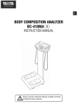
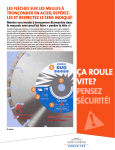
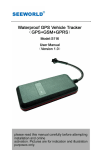
THE INTELLIGENT MOTION SENSOR TRACKING LIGHT INSTALLATION INSTRUCTIONS Read all instructions before proceeding with the installation For customer service, please call +44 (0) 845 900 6764 or email: [email protected] OVERVIEW OF NW200 Push-button 3 motion sensors INSTALLING THE BULB Unscrew the lamp cover of the luminaire and install a 150W J-type lamp or the new energy saving Grade C 120w bulb (as supplied). Re-fit the lamp cover and tighten the screws. IMPORTANT: THE INTALLATION OF THIS FITTING MUST BE DONE BY A QUALIFIED ELECTRICIAN. This fitting must be earthed. Do not mount the luminaire against inflammable surfaces. The motion detector will not operate correctly if it is installed: ( ( ( BEFORE ATTEMPTING ANY INSTALLATION OR Ⅰ) Near the outlet of aMAINTENANCE, central heatingENSURE boiler THAT THE Ⅱ) Near air conditioning plant ELECTRICAL SUPPLY IS SWITCHED OFF AND THE vehicles CIRCUIT FUSES REMOVED OR THE Ⅲ) Pointing directly at moving BREAKER IS IN THE “OFF”POSITION. Ⅳ) W ithin sight ofCIRCUIT reflection from moving water ( Ⅴ) W here other lamps could shine onto the detector ( WARNING ! ! ! The maximum rating of this luminaire is 150 Watts. Check that the total load of the circuit. Including this luminaire. Does not exceed the rating of the circuit cable. NOTE: This highly responsive unit may occasionally activate due to rapid environmental changes. 30 seconds warm-up time before the sensor resumes normal activity. Allow for approximately MOUNTING THE FITTING To ensure correct operation of the sensor, mount the luminaire that traffic passes across the detector. TOP VIEW GOOD SENSITIVITY LESS SENSITIVITY INSTALLATION AND WIRING INSTRUCTIONS Remove the inset back mounting box from the luminaire. Fit the inset back mounting box onto the wall and tighten the screws at a height that ensures adequate coverage of the area by the infrared detector. The minimum installation height is 2 meters. And the maximum height is 3 meters. NOTE: DO NOT REMOVE THE SECURING TAPE ON THE FITTING UNTIL THE UNIT IS FULLY INSTALLED. WIRING INSTRUCTIONS Feed the cable carefully through the back mounting box and bush to avoid abrasion to the cable. Connect the earth wire to the connector opposite the green/yellow cable. Connect the brown phase conductor active to the connector opposite the brown cable and tighten the screws. Connect the blue neutral conductor to the connector opposite the blue cable and tighten the screws. Check that all connections are correct and tight, as any misconnections will damage the detector. Re-fit the fitting to the back mounting box. FUNCTION This light is equipped with 3 motion sensors: zone 1 covers 60 degree, zone 2 covers 100 degrees and zone 3 covers 60 degrees. 220 degrees (maximum) in total for 3 zones. ZONE 2 ZONE 1 ZONE 3 TOTAL DETECTION RANGE The light will switch on for 3 minutes and off automatically when heat/ movement is detected. The factory default: the light on is fixed at 3 minutes and is set to Night-time mode. To change the mode to All Day Mode, push the button at the bottom of the housing and the hidden LED indicator will turn off under this mode. The light will be on at 3 minutes when detecting any movement at day and night. Push-button for programmable functions: - All day mode: light works on day and night Push-button - Night-time mode: light works at night only Reset function: If the stepper motor of tracking light works abnormally, the hidden LED indicator will flash in red and the light will stop turning automatically. In All Day mode, the red light will flash for 5 seconds and off for 5 seconds; in Night-time mode, the red light will flash in the regular pattern. Please simply switch off and on the mains power to resume the tracking light. Below are the possible abnormal situations. - External force: the light head is blocked by objects or is blown by strong wind and is unable to turn properly, the hidden LED will flash in red to signal users the abnormal situation. - Stepper Motor : when the stepper motor is reaching the end of its life or is damaged, the bottom hidden LED will flash red to signal a malfunction. Please switch the NW200 off and on at the mains, the tracking light now may or may not resume operation. If the stepper motor stops working and is outside the standard warranty period, the NW200 will continue to function as a regular motion sensor security light. Left 70° Hidden LED indicator Right 70° OPERATION 1. Turn on the wall switch to activate the light, the light is now under Night-time mode NOTE: Allow approximately 30 seconds warm-up time before the sensor resumes normal activity. 2. To test, walk through the sensor’s detection area. 3. After the light is activated, keep out of detection area and the light will switch off automatically after 3 minutes. The light will be activated again when detecting any movement. If there is continuing movement in the detection zone, the light will stay on until movement ceases. (after 3 minutes) LAMP REPLACEMENT To isolate the unit, first switch off the unit from the mains power. Allow bulb to cool before attempting to remove it. Unscrew the lamp cover and take the old lamp out and replace with new one, close the lamp cover and tighten the screws. WARNING: This fitting will become hot when in use. Allow bulb to cool before touching. NOTE: TH E INTEL LIGEN T M O TIO N SENSO R TR ACK IN G LI GH T I S DESI GNED TO ILLUM INATE WH EN TH E DETECTIO N AR E A IS ENTERED BY A PER SO N AND WI LL DETECT M O VING H E AT SO URCE. TH ERE IS NO GU AR ANTEE IM PLIED TH AT IT WILL PRO VIDE TO T AL SECURITY O R PRE VENT ILLE G AL ENTRY. SPECIFICATION Detection method: Passive Infrared Sensor (with continuous detect function) Sensor range: 10m x 220° (maximum) Power source: AC 240V Time adjustment: Fixed at 3 minutes approx. Load rating: Grade C 120 Watts (as supplied) or J-Type 150 Watts Max.